JP2004502161A - Method and apparatus for monitoring structural fatigue and use - Google Patents
Method and apparatus for monitoring structural fatigue and use Download PDFInfo
- Publication number
- JP2004502161A JP2004502161A JP2002506058A JP2002506058A JP2004502161A JP 2004502161 A JP2004502161 A JP 2004502161A JP 2002506058 A JP2002506058 A JP 2002506058A JP 2002506058 A JP2002506058 A JP 2002506058A JP 2004502161 A JP2004502161 A JP 2004502161A
- Authority
- JP
- Japan
- Prior art keywords
- stress
- recording
- data
- processing
- reading
- Prior art date
- Legal status (The legal status is an assumption and is not a legal conclusion. Google has not performed a legal analysis and makes no representation as to the accuracy of the status listed.)
- Pending
Links
- 238000012544 monitoring process Methods 0.000 title claims abstract description 38
- 238000000034 method Methods 0.000 title claims abstract description 12
- 238000005259 measurement Methods 0.000 claims abstract description 18
- 238000012545 processing Methods 0.000 claims description 55
- 238000001514 detection method Methods 0.000 claims description 19
- 230000008859 change Effects 0.000 claims description 7
- 238000001914 filtration Methods 0.000 claims description 3
- 238000004891 communication Methods 0.000 claims description 2
- 238000012806 monitoring device Methods 0.000 abstract description 46
- 238000004458 analytical method Methods 0.000 abstract description 8
- 230000008569 process Effects 0.000 abstract description 5
- 239000000463 material Substances 0.000 description 16
- 230000007613 environmental effect Effects 0.000 description 8
- 238000013500 data storage Methods 0.000 description 7
- 238000010586 diagram Methods 0.000 description 7
- 230000000977 initiatory effect Effects 0.000 description 6
- 230000007774 longterm Effects 0.000 description 5
- 230000006835 compression Effects 0.000 description 4
- 238000007906 compression Methods 0.000 description 4
- 238000005553 drilling Methods 0.000 description 4
- 239000011888 foil Substances 0.000 description 3
- 238000007689 inspection Methods 0.000 description 3
- 230000000737 periodic effect Effects 0.000 description 3
- 230000000750 progressive effect Effects 0.000 description 3
- 238000004026 adhesive bonding Methods 0.000 description 2
- 230000005540 biological transmission Effects 0.000 description 2
- 230000015556 catabolic process Effects 0.000 description 2
- 238000006731 degradation reaction Methods 0.000 description 2
- 238000013461 design Methods 0.000 description 2
- 230000009189 diving Effects 0.000 description 2
- 230000007246 mechanism Effects 0.000 description 2
- 239000004033 plastic Substances 0.000 description 2
- 229910001369 Brass Inorganic materials 0.000 description 1
- 239000006096 absorbing agent Substances 0.000 description 1
- XAGFODPZIPBFFR-UHFFFAOYSA-N aluminium Chemical compound [Al] XAGFODPZIPBFFR-UHFFFAOYSA-N 0.000 description 1
- 229910052782 aluminium Inorganic materials 0.000 description 1
- 230000015572 biosynthetic process Effects 0.000 description 1
- 239000010951 brass Substances 0.000 description 1
- 238000006243 chemical reaction Methods 0.000 description 1
- 230000000694 effects Effects 0.000 description 1
- 239000003822 epoxy resin Substances 0.000 description 1
- 239000000835 fiber Substances 0.000 description 1
- 238000005206 flow analysis Methods 0.000 description 1
- 230000003993 interaction Effects 0.000 description 1
- 230000002452 interceptive effect Effects 0.000 description 1
- WABPQHHGFIMREM-AKLPVKDBSA-N lead-210 Chemical compound [210Pb] WABPQHHGFIMREM-AKLPVKDBSA-N 0.000 description 1
- 239000004973 liquid crystal related substance Substances 0.000 description 1
- 238000007726 management method Methods 0.000 description 1
- 239000012053 oil suspension Substances 0.000 description 1
- 230000003287 optical effect Effects 0.000 description 1
- 239000013307 optical fiber Substances 0.000 description 1
- 230000010355 oscillation Effects 0.000 description 1
- 229920000647 polyepoxide Polymers 0.000 description 1
- 238000000275 quality assurance Methods 0.000 description 1
- 230000004044 response Effects 0.000 description 1
- 239000011435 rock Substances 0.000 description 1
- 230000035939 shock Effects 0.000 description 1
- 230000008054 signal transmission Effects 0.000 description 1
- 238000004088 simulation Methods 0.000 description 1
- 230000003068 static effect Effects 0.000 description 1
- 238000012546 transfer Methods 0.000 description 1
Images


Classifications
-
- G—PHYSICS
- G01—MEASURING; TESTING
- G01M—TESTING STATIC OR DYNAMIC BALANCE OF MACHINES OR STRUCTURES; TESTING OF STRUCTURES OR APPARATUS, NOT OTHERWISE PROVIDED FOR
- G01M5/00—Investigating the elasticity of structures, e.g. deflection of bridges or air-craft wings
- G01M5/0083—Investigating the elasticity of structures, e.g. deflection of bridges or air-craft wings by measuring variation of impedance, e.g. resistance, capacitance, induction
-
- G—PHYSICS
- G01—MEASURING; TESTING
- G01M—TESTING STATIC OR DYNAMIC BALANCE OF MACHINES OR STRUCTURES; TESTING OF STRUCTURES OR APPARATUS, NOT OTHERWISE PROVIDED FOR
- G01M5/00—Investigating the elasticity of structures, e.g. deflection of bridges or air-craft wings
- G01M5/0033—Investigating the elasticity of structures, e.g. deflection of bridges or air-craft wings by determining damage, crack or wear
Abstract
電子応力監視デバイス(1)が提供され、これは、応力履歴ユニットが接続される構造(2)が受けた応力の測定値を検出かつ記録するように構成され、応力の測定および記録は実質的に同じ場所で起こる。応力監視ユニット(1)はまた、検出された応力の読みを処理して、それが接続される構造(2)内で有意構造事象が起こっているときを決定するようにも構成される。これらの事象を示すデータが応力監視デバイス(1)内で記録される。定期的に応力監視デバイス(1)内に記録されたデータがデータ・リーダ(4)によって得られ、次いでコンピュータ(6)へ後続の解析のために伝送される。An electronic stress monitoring device (1) is provided, which is configured to detect and record a measurement of a stress received by a structure (2) to which a stress history unit is connected, wherein the measurement and recording of the stress is substantially performed. Happens in the same place. The stress monitoring unit (1) is also configured to process the detected stress reading to determine when a significant structural event is occurring in the structure (2) to which it is connected. Data indicating these events is recorded in the stress monitoring device (1). Periodically, data recorded in the stress monitoring device (1) is obtained by a data reader (4) and then transmitted to a computer (6) for subsequent analysis.
Description
【0001】
本願は、構造疲労を測定して、構造が受けた応力および歪みの電子記録を生成するための方法および装置に関する。本発明の実施形態は、構造上有意な事象を監視かつ記録して、構成要素の構造完全性を決定できるようにする装置に関する。
【0002】
工学構成要素が単一の負荷の適用によって破損することはめったにない。通常、加えられた負荷に対するバルク静的材料耐性は適度によく理解されており、構成要素は設計負荷を含めるように設計される。加えて、大抵の設計は安全性の要素を組み込んで不測の事象を説明するようにし、これには加えられる負荷の大きさの過小評価および材料強度の過大評価が含まれる。したがって、工学構成要素の大多数は複数の進行性の破損メカニズムの組み合わせによって破損し、これは構造材料が有する、加えられた応力に弾力的に抵抗する能力に影響を及ぼす。構造材料の進行性の低下を含む大多数の場合では、疲労という用語が頻繁に使用される。
【0003】
疲労は、単一の適用において破損を引き起こすであろう大きさに決して達しない、変動する負荷の下の、材料の構造的劣化として規定することができる。これは進行性の現象であり、疲労破損状態に達するまでに要する時間が直接、局所応力/歪みの振動および構造上有意的な事象の大きさおよび数に関係する。疲労に帰する多数の異なるメカニズムがあるが、すべてが、加えられた負荷の性質に対してある関係を有する。
【0004】
疲労プロセスが2つの異なる段階からなるという、一般的な容認がある。第1の段階は疲労亀裂発生である。これは、材料が周期的に応力を受け、明らかな連続体として反応する期間、すなわち、応力を加えることで材料の均一性にダメージを引き起こしているという肉眼的な形跡がない期間である。しかし、実際には、応力/歪みの周期がしきい値の大きさを上回った場合、マイクロメカニズムが材料の構造における肉眼的な不連続性の生成に寄与し、これらが頻繁に増大して疲労亀裂になることが知られている。
【0005】
疲労プロセスの第2の段階は疲労亀裂伝播である。これは、亀裂のサイズが、荷重の性質、亀裂が増大する材料、および亀裂がさらされる環境に応じて変化する率で増大する期間である。最後に、亀裂が臨界サイズに達するとき、構成要素が相対的に短い期間で破損するようになる。
【0006】
構造完全性の管理は、構造の有効寿命中に構造に適用された品質保証の拡張である。構造がそれに対して判断される、基礎をなすチェックは、それが目的に適当であるかどうかであり、すなわち、ある程度のダメージおよび/または負荷の増大を許容することはできるが、構造が継続的あるいは定期的に、それが設計された目的のタスクを安全に行うためのその能力について評価されなければならない。
【0007】
疲労亀裂伝播は相対的に監視しやすく(よって、多数の商用亀裂検査計器が入手可能である)、これは亀裂の肉眼的な性質のためである。亀裂/きずが検出された後、これを相対的、正確に測定することができ、線形弾性破壊力学解析を適用して、亀裂が臨界サイズに発展するまでの時間を理解することができる。これは一般降伏および破壊解析を使用して決定される。
【0008】
対照的に、疲労亀裂発生段階中に費やされたダメージの部分を直接測定することができる、入手可能な計器はない。その代わりに、業界は、解析的かつ数値的な予測モデルに基づいた定期的な亀裂の検査に依拠している。これらはすべてのシミュレーションと同様に完全性査定エンジニアの技術および経験に敏感であり、後続の亀裂の発見が検査員の技術および検査方法の性能に依存する。
【0009】
疲労亀裂発生モニタの欠乏は完全性査定には実際の欠点であり、特に、ある高度に完成された構造構成要素(たとえば、シャフト、スピンドル、ベアリング・ハウジング、ローター・ブレードなど)において、総合的な疲労寿命がしばしば最大90%の疲労亀裂発生および10%の疲労亀裂伝播を含む可能性があることを考慮するとき、そうである。
【0010】
航空機の機体の場合、電気歪みゲージを設けて、航空機が受けた歪みにおける変動を測定することが知られている。いくつかの歪みゲージによって航空機の様々な位置で生成された信号が次いで中央記録デバイスに送り込まれ、そこで信号がデジタル化され、信号の表現が磁気テープ上に記録される。米国特許出願第4336595号では、歪みデータを得ることと、その後続の解釈の間に生じた遅延が望ましくないことが認識されており、したがって、検出された信号が単に記録されるのではなく、航空機に搭載されたコンピュータ内で自動処理されるべきであることが提案された。
【0011】
組み込みの監視システムのさらなる実施例が、米国特許出願第5531122号に開示されている。これはトラックのための監視システムを開示しており、ショック・アブソーバにおけるオイル・サスペンション・ストラット内の圧力が監視されるものである。しかし、米国特許出願第4336595号および米国特許出願第5531122号は監視システムの実施例であるが、米国特許出願第4336595号のシステムも、米国特許出願第5531122号に記載されたシステムも、様々な異なる構造を監視するための用途に適切ではない。
【0012】
応力測定値を自動処理するためのデバイスの一実施例が、欧州特許第0856817号に開示されている。これは、歪みゲージ・ポートを介して外部歪みゲージに接続することができるデバイスを開示している。外部歪みゲージからの読み取りが次いで、レイン・フロー解析を利用して自動処理されて、疲労を示す値のセットが得られる。
【0013】
本発明の一態様によれば、装置が接続される構造が受けた歪みを検出かつ記録するための装置が提供され、前記装置は、
一端で開いているハウジングと、
固定されるように、かつ、装置が接続される構造が受けた歪みを測定するように構成された歪みゲージと、
前記歪みゲージによる歪みの測定値を格納するための電子データ格納手段と、
前記歪みゲージからの歪みの測定値を前記データ格納手段に転送するための配線手段とを含み、
前記歪みゲージにおいて、前記配線手段および前記電子データ格納手段がすべて前記ハウジング内に含まれることを特徴とする。
【0014】
本発明のこの態様によれば、元の場所に歪み検出器のみを含むのではなく、歪み検出器と実質的に同じ位置に位置する、そこからデータを記録/格納するための手段も含むデバイスが提供される。これは、高度に忠実な信号の記録を将来の解析のために行うことができることを意味する。歪み検出デバイスとデータ記憶装置の間の配線の距離および長さを最小にすることによって信号の劣化を低減することが可能であり、これは温度、電気的な電磁干渉を、歪みゲージとデータ格納システムの間の信号の伝送から除くことによって行う。誤差の源をなくすことによって、構造が受けた歪みの改善された記録を得ることができる。
【0015】
本発明のさらなる態様によれば、装置が接続される構造にかけられた歪みを記録するためのデバイスが提供され、前記装置は、
一端で開いているハウジングと、
前記ハウジング内に取り付けられ、装置が接続される構造にかけられた歪みを検出するための歪み検出手段と、
前記ハウジング内に取り付けられたデータ格納手段であって、前記歪み検出手段によって検出された歪みを示すデータを格納するように構成されるデータ格納手段とを含み、
前記歪み検出手段によって検出された前記歪み、および前記データ格納手段に格納されたデータから、有意構造事象が起こっているときを決定するための決定手段をさらに含み、前記データ格納手段が、前記決定手段によって決定された有意構造事象を示すデータを記録するように構成されることを特徴とする。
【0016】
出願人は、構造が受けた応力を測定するための実験用装置が存在するが、このような実験用装置が主として精度の高い応力および歪みの測定値を得ることを目的とすることを理解している。しかし、このような精度の高さは、構成要素の構造完全性における応力の長期の効果の決定において必要ではなく、これはデータの多くが不必要であり、精度の高い応力の読みは必要とされないからである。したがって、本発明のこの態様によれば、測定された応力読み取りから、構成要素の構造的使用の程度を決定するための手段が提供される。これは、有意構造事象が起こっているかどうかを決定すること、およびこのような事象が起こるときにのみデータを記録することによって達成される。このようにして、周期的な硬化および軟化の結果となる応力の記録、可変振幅循環による負荷相互作用効果、個々の構造についてのコアキシングおよび休止期間などを決定することができる。したがって、構成要素の使用の量を測定することができる。
【0017】
出願人はさらに、構成要素または構造の寿命全体を通じて応力を読み取りかつ記録するための装置を提供することによって、デバイスまたは構造内の疲労を、特に亀裂発生段階中に監視することができる手段が提供されることを理解している。構造の寿命全体を通じて応力を測定かつ読み取るために、構造の寿命全体について監視かつ記録するために十分な電力を供給する電源も提供されなければならない。これは、たとえば太陽電池板など再生可能な電源を提供すること、または別法として、電力消費を最小限にして、バッテリなど非再生可能な電源を、監視中の構造の実質的な寿命について装置に供給できるようにする方法で、測定手段および記録手段を構成することによって達成することができる。
【0018】
本発明のさらなる態様および実施形態は、以下の記載および図面を参照して明らかになるであろう。
【0019】
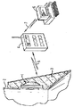
図1は本発明の第1の実施形態の概略図である。本発明のこの実施形態による応力監視デバイス1は、ドリル・ストリング2にかけられた応力および歪みを監視するように構成され、ドリル・ストリング2は、石油およびガス掘削装置の一部として岩盤を切り開くためのドリル・ビット(図1に図示せず)を回転されるために使用される。
【0020】
本発明のこの実施形態によれば、応力監視デバイス1がドリル・ストリング2の表面に接続され、ドリル・ストリング2の応力が監視される。次いで、ドリル・ストリング2および応力監視デバイス1が表面硬化3によって覆われ、これは、ドリル・ストリング2の使用中に応力監視デバイス1がダメージを受けないように保護するように動作する。
【0021】
配置された後、応力監視デバイス1が、ドリル・ストリング2にかけられた応力および歪みを継続的に監視かつ記録する。応力監視デバイスによって検出された有意構造事象を示すデータが、応力監視デバイス1のメモリ(図1に図示せず)内に記録される。
【0022】
定期的に、ドリル・ストリングが表面に戻されるとき、応力監視デバイス1がデータ・リーダ4によって問合せられ、これは応力監視デバイス1のメモリ内からデータ・リーダ4に、無線リンク5を用いてデータをダウンロードするように構成される。したがってこのようにして、応力監視デバイス1によって記録されたデータに、応力監視デバイス1をドリル・ストリング2から除去するか、あるいは応力監視デバイスを保護する表面硬化3を除去することなく、アクセスすることができる。
【0023】
応力監視デバイス1のメモリからのデータがデータ・リーダ4にコピーされているとき、このデータをさらにコンピュータ6へデータ・リーダ4から、第2の無線リンク7によって転送することができ、そこで、応力監視デバイス1によって記録されたデータがさらなる解析を受けることができる。
【0024】
ドリル・ストリング2が受けた応力を継続に監視するために構成される応力監視デバイス1を提供することによって、疲労亀裂発生の監視を可能にするための手段が提供される。詳細には、本発明のこの実施形態によれば、応力監視デバイス1が、地下で使用されたドリル・ストリング2における応力を監視するために提供され、応力の記録を格納するメモリを提供することによって、ドリル・ストリングが地下にあるとき、応力監視デバイス1との通信が困難であるためにデータをデータ・リーダ4によって定期的にしか得ることができなくとも、ドリル・ストリング2のユーザ中で応力の記録を得るための手段が提供される。ドリル・ストリングの使用を、監視された応力に基づいて中断することによって、したがって掘削動作中のドリル・ストリングのダウン・ホール破損を回避することができる。
【0025】
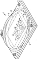
本発明のこの実施形態による応力監視デバイス1の物理構造をこのとき図2および3を参照して記載し、図2は本発明のこの実施形態による応力監視デバイスの概略的斜視図であり、図3は応力監視デバイス1の断面図である。
【0026】
本発明のこの実施形態によれば、応力監視デバイス1が60×80mmの長方形のプレート10を含み、これは10×20mmの長方形の穴11を中央に有する。この実施形態では、長方形のプレートが15mmの厚さの真鍮のプレートである。しかし、他の実施形態では、たとえばプラスチック、アルミニウムなど、相対的に強く成形することができるいかなる適切な材料も使用できることは理解されよう。この長方形のプレート10が、エポキシ樹脂によってドリル・ストリング2の表面に接着される。長方形のプレート10の4隅にネジ穴12が設けられ、これは、カバー16を長方形のプレート10に固定するためのネジ14を受け入れるように構成される。
【0027】
この実施形態では、カバー16が60×80mmの長方形の硬質プラスチック製のカバーを含み、その表面に半卵形のドームを設けており、これが長方形のプレート10の中央の上面から24mmの距離まで立ち上り、それによりカバー16のドームと長方形のプレート10の上面の間の空洞20を規定する。ドームによって占有されていないカバー16の4隅が伸びてフランジを形成し、各フランジがその中にさらにネジ穴22を設けており、これをネジ14が通過してカバー16の位置をプレート10に相対的に固定する。長方形のプレート10をドリル・ストリング2の表面に接着し、次いでカバー16をプレート10に、ネジ14をネジ穴12、22に挿入することによって接着することによって、カバー16をドリル・ストリング2へ、穴をドリル・ストリング2自体に掘ることなく、したがってドリル・ストリング2の構造完全性に影響を及ぼすことなく固定するための手段が提供される。
【0028】
長方形のプレート10の穴11内に設けられたものが、第1の電子歪みゲージ22および第2の電子歪みゲージ24であり、これらは従来の電子ロゼット歪みゲージを含み、これらがそれぞれ3つの方向における歪みを、ロゼット内のワイヤの引張により生じる抵抗における変化に基づいて測定するように構成される。第1の歪みゲージ22がドリル・ストリング2の表面に接着され、第1の歪みゲージ22の電気抵抗がドリル・ストリング2にかけられた応力および歪みに従って変動するようにされる。本発明のこの実施形態では、第2の歪みゲージ24が、温度における変化など、環境の変化を測定するように構成され、これが結果として歪みゲージ22、24からの読み取りにおける変動となる。したがって、第2の歪みゲージ24が耐力構造の表面に固定されるのではなく、その代わりにドリル・ストリング2が製造される元の材料に対応する材料の非耐力ホイル25に固定される。したがってこのようにして、かけられた応力以外の環境要因からのみ生じる電気抵抗における変動を、ホイル25がドリル・ストリング2の材料に類似の方法で膨張かつ収縮するときに決定することができる。第2の歪みゲージ24による歪みの読み取りにおける変動を、第1の歪みゲージ22の読み取りから差し引くことによって、ドリル・ストリング2が加えられた負荷によってのみ受けた応力および歪みの記録を得ることができる。第2の歪みセンサ24をダミーのゲージとして設けることにより、環境要因から生じる抵抗における変動を、著しい処理能力を必要とすることなく決定できるようになり、したがって相対的に少量の電力を達成することが必要となる。
【0029】
第1の歪みゲージ22および第2の歪みゲージ24が処理装置30に接続され、これはカバー16のドームおよび長方形のプレート10の上面によって規定された空洞20内に、ワイヤ32、34を用いて設けられる。この実施形態では、これらのワイヤ32、34が、歪みゲージ22、24から処理装置30まで約20mmの距離だけ伸びる。
【0030】
処理装置30を、カバー16および長方形のプレート10によって規定されたハウジング内に設けることにより、歪みゲージ22、24から得られたデータを実質的に元の場所に記録することができる手段も提供される。これにより、応力監視デバイス1を展開して、回転あるいは移動するドリル・ストリング2などの構造が受けた歪みを測定することができ、これは、歪みゲージ22、24に相対的な処理装置30の有意的に相対的な移動が生じないからである。
【0031】
ワイヤ32、34は、電流を歪みゲージ22、24から処理装置30に転送するように構成される。歪みゲージ22、24のそれぞれについて、応力が監視される3つの方向に垂直に構成された配線を含む3つの各回路における抵抗の小さい変動を、次いで回路における電流の変動から決定することができる。その中で電流が測定される回路は、歪みゲージ22、24の測定配線、および歪みゲージ22、24を処理装置30に接続するワイヤ32、34を含む。これらの回路における抵抗は、第1の歪みゲージ22のワイヤの場合、温度における変化などの環境要因により、かつ負荷をドリル・ストリング2に加えることによる引張により変動する。第2の歪みゲージ24の場合、これが耐力表面に接着されないので、第2の歪みゲージ24のワイヤにおける抵抗の変動は環境要因のみによる。
【0032】
次いで、これらの抵抗の測定値を、ドリル・ストリング2が受けた歪みの測定値に変換することができ、これについては以下で詳細に記載する。
【0033】
出願人は、歪みの測定値を決定するために使用された抵抗における変動が小さいので、歪みゲージ22、24を処理装置30に接続する配線32、34の抵抗における変動が、歪みゲージから得られた歪みの読み取りにおける誤差の有意な原因になる可能性があることを理解している。詳細には、電気歪みゲージ22、24による歪みの測定値が歪みゲージ22、24における抵抗の非常に小さい変化、たとえば120Ωの抵抗の歪みゲージにおいて約20mΩの変化のみを引き起こすので、抵抗において比較可能な変化を、歪みゲージ22、24を処理装置に接続する配線32、34の熱膨張または振動の結果として生成することもできる。したがって、これらの誤差を最小にするために、歪みゲージ22、24を処理装置30に接続するワイヤ32、34のこれらの長さが可能な限り短くされて、歪みゲージ22、24によって生成された信号が処理装置30によって増幅される前に誤差が最小限にされる。さらに、これらのワイヤ32、34が、カバー16のドームによって、かつしたがって、カバー16および表面硬化3によって外部環境における変動から保護されたある範囲に規定された空洞20内に含まれる。
【0034】
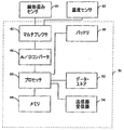
図4は、第1の歪みセンサ22および第2の歪みセンサ24に、それぞれ短い長さのワイヤ32および34によって接続された処理装置30のブロック図である。
【0035】
本発明のこの実施形態では、処理装置30がマルチプレクサ40を含み、これが、第1の歪みセンサ22および第2の歪みセンサ24に接続されたワイヤ32および34に接続される。処理装置30はまたアナログ/デジタル・コンバータ42も含み、これがマルチプレクサ40、プロセッサ44、メモリ46、バッテリ48、クロック50、一時データ・ストア52および受信器/送信器54に接続される。
【0036】
プロセッサ44はアナログ/デジタル・コンバータ42に接続されることに加えて、メモリ46、処理装置30に電力供給するためのバッテリ48、クロック50、一時データ・ストア52および受信器送信器54にも接続される。
【0037】
マルチプレクサ40は、第1の歪みセンサ22および第2の歪みセンサ24からの信号を同時に受信するように構成される。マルチプレクサ40は、第1の歪みセンサ22および第2の歪みセンサ24から受信された同時読み取りを6つの別々の信号に変換し、これらは歪みセンサ22、24の3つの各回路における電流の測定値であり、これらが次いで、マルチプレクサに接続されたアナログ・デジタル・コンバータ42に渡される。アナログ・デジタル・コンバータ42が、マルチプレクサ40によって出力されたアナログ信号をデジタル信号に変換し、これらが次いで、アナログ・デジタル・コンバータ42に接続されたプロセッサ44に渡される。
【0038】
プロセッサ44は、アナログ・デジタル・コンバータ42によって出力された信号を、データ・ストア52内に格納する前に増幅するように構成される。プロセッサ44はまた、一時データ・ストア52内のデータ、およびアナログ・デジタル・コンバータ42から受信かつ増幅された信号から、構造上有意な事象が起こっているかどうかを決定するようにも構成される。以下で詳細に記載するように、このような事象が起こっていると決定されているとき、事象およびそれが起こった時間を示すデータがメモリ46に格納される。
【0039】
この実施形態におけるデータ・ストア52は、プロセッサによって有意構造事象が起こっているかどうかを決定するために使用されたデータを格納するように構成される。したがって、データ・ストア52はデータを短い期間について格納するように構成され、その間にデータの有意性を査定することができる。メモリ46は対照的に長い期間のデータ・ストアであり、これは、応力監視デバイスが接続される構造が受けた有意構造事象の永続的記録を提供するように意図される。この実施形態におけるメモリ46はフラッシュRAMを含み、これによりデータをメモリ46から、メモリ46の処理に干渉することなく読み出すことができる。
【0040】
送信器/受信器54は、無線メッセージをデータ・リーダ4から受信するように構成される。これが起こるとき、送信器/受信器54が信号をプロセッサ44に渡し、これが次いでプロセッサ44にデータをメモリ46から検索させ、これが次いで無線信号として送信器受信器54によってデータ・リーダ4へ送信される。したがってこのようにして、メモリ46の内容をデータ・リーダ4のメモリに、後続の解析のためにコピーすることができる。
【0041】
本発明のこの実施形態による、処理装置30におけるプロセッサ44による信号の処理をこのとき図5を参照して記載する。
【0042】
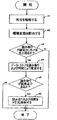
図5は、本発明のこの実施形態によるプロセッサ44の処理の流れ図である。定期的に、たとえば1.5ミリ秒毎に、プロセッサ44が、アナログ・デジタル・コンバータ42から得られた信号を処理する。本発明のこの実施形態におけるアナログ・デジタル・コンバータ42からの信号は4つの信号を含み、第1の歪みセンサからの3つの信号は、歪みセンサ22からの3つの方向における歪みの読み取り対応し、1つの信号は、第2の歪みセンサ24からの1つの読み取りに対応する。プロセッサ44がこれらの4つの信号をアナログ/デジタル・コンバータ42から得るとき、プロセッサ44が最初に(s1)これらの信号を5,000倍にデジタルで増幅する。
【0043】
次いで(s2)プロセッサ44が、第1の歪みセンサ22からの読み取りが得られた3つの方向についての増幅された信号から、第2の歪みセンサ24によって得られた読み取りを差し引く。
【0044】
第1の歪みセンサ22のみがドリル・ストリング2の表面に接着されるので、第1の歪みセンサ22のみが、ドリル・ストリング2にかけられた応力および歪みによって影響される。したがって、第2の歪みセンサ24からの読み取りにおけるいかなる変動も、応力監視デバイス1が受ける温度における変動など、環境要因によってのみ生じる。したがって、第2の歪みセンサ24からの読み取りを、第1の歪みセンサ22の読み取りから差し引くことによって、3つの異なる方向においてドリル・ストリング2にかけられた応力についての3つの値のセットが得られ、これは環境要因による影響を受けないものである。
【0045】
第1の歪みセンサ22についての読み取りが、第2の歪みセンサ24から対応する読み取りを差し引くことによって修正された後、次いで(s3)プロセッサ44が、3つの各読み取りについて、各読み取りと先にデータ・ストア52内に格納された対応する読み取りの間の差が雑音のしきい値を超えるかどうかを決定する。環境要因を説明するように修正された、歪みセンサ22の読み取りがすべて実質的に、先にデータ・ストア52に格納された値に等しい場合、これは、ドリル・ストリング2にかけられた応力が、先に応力の決定が行われたときから有意的に変動していないことを示す。歪みセンサの読み取りをこのようにフィルタリングすることによって、たとえばワイヤ32、34における振動により生じる小さい誤差は、ドリル・ストリング2に影響を及ぼす事象として記録されない。
【0046】
第1の歪みセンサからのすべての読み取りが、先にデータ・ストア52に格納されたものに実質的に対応する場合、次の信号がアナログ・デジタル・コンバータ42から受信されるまで、さらなる動作がプロセッサ44によってとられない。
【0047】
しかし、歪みセンサ22からの読み取りがしきい値の量より大きい量だけ変動する場合、次いで(s4)新しいセットの読み取りがデータ・ストア52内に、プロセッサ44が歪みセンサ22からの読み取りを得た時間についてクロック50によって示された時間を示すデータと共に格納され、最後の読み取りの前に、その読み取りの以前にデータ・ストア52内に格納された読み取りに対応する値が上書きされる。したがってこのようにして、データ・ストア52がその中に、雑音のしきい値より大きい量だけ互いに異なる3つの連続的な読み取りについての環境要因を説明するように増幅かつ修正された、第1の歪みセンサ22からの3つの読み取りのセットを格納しており、3つの読み取りの各セットは、ドリル・ストリング2内の3つの異なる方向における歪みを示す3つの値を含む。
【0048】
次いで(s5)プロセッサ44が、データ・ストア52内に格納されたデータが、ドリル・ストリング2にかけられた歪みが最大または最小のいずれかに達していることを示すかどうかを決定する(s5)。これは、プロセッサ44が、特定の方向における応力の測定値に対応する各値について、特定の方向についてデータ・ストア52内に格納された3つの読み取りの中間に対応する値が、その方向における応力についての他の2つの読み取りの両方より大きいあるいは小さいかどうかを決定することによって達成される。これがそうである場合、次いで(s6)プロセッサ44が、第1の歪みセンサ22によって3つの方向において検出された歪みについての3つの値を含む中間の読み取りに対応するデータ、および、値が測定されたクロック50上の時間に対応する時間データをメモリ46に格納する。次いで、プロセッサ44の処理が、プロセッサ44によってアナログ・デジタル・コンバータから受信された次の信号が処理されるまで、終了する。
【0049】
したがってこのようにして、最大の圧縮または伸張を示す、ドリル・ストリング2にかけられた歪みを示すデータがメモリ46内に、このような膨張および圧縮が起こった時間と共に記録される。このデータが、データ・リーダ4を使用して読み出されるとき、次いでデータを従来の方法でレイン・フローまたはレンジ・ペア解析によって処理して、ドリル・ストリング2が受けた負荷シーケンスを識別することができ、そこからドリル・ストリング2が受けた疲労を決定することができる。読み取りから計算された疲労がしきい値を超えているとき、ドリル・ストリング2の使用を中断させて、ダウン・ホール破損がドリル・ストリング2の構造上の破損の結果として生じないように保証することができる。
【0050】
本発明の第2の実施形態をこのとき図6を参照して記載する。本発明の第1の実施形態では応力監視デバイスを記載し、これは監視デバイス1に接続されたデバイスにかけられた最大および最小の応力を記録するように構成されるものである。本発明のこの実施形態では、最大および最小の応力の期間を含む有意構造事象を記録することに加えて、この実施形態による監視デバイス1はまた、これが接続されるデバイスに外部構造応力が加えられないときの休止期間を示すデータを記録するようにも構成される。
【0051】
本発明のこの実施形態における応力監視デバイス1は、第1の実施形態に関連して記載したものと等しいが、ただしプロセッサ44が、アナログ・デジタル・コンバータ42から受信されたデータを、図6を参照して以下に記載する方法で処理するように構成される。
【0052】
図6は、本発明の第2の実施形態によるプロセッサ44の流れ図である。本発明のこの実施形態によるプロセッサ44の処理は、第1の実施形態に関連して記載したものと等しく、これをここでは繰り返さないが、ただし(s3)のとき、プロセッサが、第2の歪みセンサ24からの対応する読み取りを差し引くことによって修正された、第1の歪みセンサ22からの読み取りが、データ・ストア52内に格納された対応する読み取りに実質的に対応すると決定されることを決定する。
【0053】
この実施形態では、これが起こるとき、プロセッサ44が次いで(s7)休止期間が起こっているかどうかを、クロック50上の現在時間を、メモリ46内に記録された歪みの最後に記録された測定値に関連付けられた時間と比較することによって決定する(s7)。クロック50上の読み取りと、メモリ46内に最後に記録された読み取りの間の時間差が所定のしきい値を上回る場合、これは、応力監視デバイス1が接続されるデバイス内の構造応力における変動が、このあらかじめ設定されたしきい値より大きい期間について起こっていないことを示し、次いで、休止期間の長さを示すデータがデータ・ストア52内に格納される(s8)。
【0054】
データがデータ・ストア52に格納されたか(s8)、あるいはプロセッサ44が、休止期間が起こっていないと決定した後(s7)、次いでプロセッサ44の処理が終了する。
【0055】
転換点に対応すると決定された応力における変動(s5)が検出されるとき、プロセッサ44が、この読み取りに対応するデータ、およびメモリ内のデータ・ストア52内に記録された先の休止期間の時間の長さを識別するデータを格納する。次いで、データ・ストア52内の休止期間データがゼロに設定される。
【0056】
したがってこのようにして、メモリ46内に、応力監視デバイス1が接続されるデバイスにかけられた最大および最小の応力を識別するデータを格納しておくことに加えて、メモリ46はまたその中に、応力における変動が起こらない期間の発生の期間および時間を識別するデータも格納している。次いで、このデータをメモリ46から、第1の実施形態に関連して記載したものと同じ方法で読み出すことができる。
【0057】
本発明の第3の実施形態を以下に記載する。本発明の先の2つの実施形態では、応力監視デバイス1を記載し、これは、応力監視デバイス1が接続されるデバイスまたは構成要素にかけられた最大および最小の応力を示すデータを記録するように構成される。デバイスまたは構成要素にかけられる応力の有用な記録を提供するが、いくつかの応用例、詳細には、応力が頻繁に変動するか、あるいは応力が長期間にわたって監視される応用例では、大量のデータを格納する必要性により問題が生じる可能性がある。
【0058】
したがって、本発明のこの実施形態によれば、第1の実施形態に記載したようなデータの処理および記録に加えて、この実施形態では、定期的に、応力監視デバイス1のメモリ46内に格納されたデータ自体が、格納される処理の結果により処理され、同時にメモリ46において応力監視デバイス1によって得られた実際のデータを次いで上書きすることができる。
【0059】
本発明のための応用例は、デバイスおよび構成要素の長期の構造監視について、構成要素およびデバイス内で疲労から生じる変化が、構成要素またはデバイスが加えられた負荷に反応する方法における変動を起こすことを理解している。詳細には、デバイスまたは構成要素の一部が応力を加えられる方法における長期の変動が、応力が測定中であるところから遠く離れたデバイスまたは構成要素の一部における亀裂の生成を示すことができる。
【0060】
したがって、本発明のこの実施形態によれば、あらかじめ設定された測定の期間がメモリ46内に格納された後、この実施形態によるプロセッサ44が、応力がなおロゼット歪みセンサ22によって監視される3つの方向についての読み取りの平均比率を決定する。次いで、これらの計算された比率がメモリ46内に格納される。次いで、プロセッサ44が進行して、先に記録された、メモリ46内に格納された、対応するあらかじめ設定された期間についての最大および最小の応力の測定値を上書きし、次いでさらなる比率データが記録される。このサイクルが繰り返され、比率データがメモリ46内で累積する。データがメモリ46から読み出されるとき、歪みセンサ22によって測定された3つの方向における歪みの比率が経時的に変動する方法を次いで決定し、応力監視デバイス1が接続されるデバイスまたは構成要素内の障害および亀裂の生成を計算できるようにすることができる。
【0061】
上に記載した実施形態では、3つの方向において測定された応力の異なる平均比率のうちの比率が、最大および最小の応力の読みが格納される各期間について記録されるものとして記載された装置を記載した。データを格納するためのメモリ要件をさらに減らすことができ、これはメモリ46内に、平均比率が、先の期間についての比率からあらかじめ設定されたしきい値とは異なる期間についての平均比率についてのデータを格納することのみによることは理解されよう。したがってこのようにして、より少ないデータをメモリ46内に格納することが必要となり、同時に監視中の構成要素またはデバイスが加えられた応力に反応する方法における傾向を決定することができる。
【0062】
この実施形態では、応力の処理読み取りを参照して、異なる方向において受けた平均応力の比率を識別するデータを得たが、検出された応力の大きさが経時的に変動した方法を識別するデータを生成して、記録された応力監視デバイス1が接続される構成要素またはデバイスが加えられた負荷に対するその反応において異なる方法の記録を提供することもできることは理解されよう。
【0063】
本発明の第4の実施形態を、このとき図7および8を参照して記載する。図7は、この実施形態による処理装置30のブロック図である。本発明のこの実施形態は、第1の実施形態に関連して記載したものと等しいが、ただし、処理装置30が第1の歪みセンサ22および第2の歪みセンサに接続され、第1の歪みセンサ22および第2の歪みセンサ24がロゼット歪みセンサではなく、この実施形態では、処理装置30が線形歪みセンサ60へ、かつ温度センサ62へ接続される。この実施形態による処理装置30はまた修正もされ、クロックが設けられず、プロセッサ44が代替プロセッサ65によって置き換えられ、これは線形歪みセンサ60および温度センサ62からの信号を利用するように構成される。
【0064】
この実施形態では、応力監視ユニットが提供されて、構成要素または構造が単一の方向において受けた応力が監視される。単一の方向における応力を測定するように構成された線形歪みセンサ60を提供することによって、処理装置30の処理要件を減らすことができ、これは1つの歪みの測定値のみが処理されるからである。
【0065】
図8は、本発明のこの実施形態によるプロセッサ65の処理の流れ図である。第1の実施形態に関連するように、歪みセンサ60および温度センサ62からマルチプレクサ40によって受信された信号が、プロセッサ65に出力される前にアナログ・デジタル・コンバータ42へ渡される。次いで(s11)、線形歪みセンサ60からの信号がプロセッサ65によって、第1の実施形態に関連して記載されたものと類似の方法で増幅される。次いで(s12)プロセッサ65が、増幅された信号を、温度センサ62によって示された温度における変動を説明するように修正する。
【0066】
次いで(s13)修正された信号が、データ・ストア52により格納されたデータと比較される。本発明のこの実施形態では、データ・ストアが、プロセッサ65によって増幅かつ修正された、線形歪みセンサ60から得られた3つの先の読み取りに対応するデータ、およびメモリ46に格納された最新の転換点値についての値を格納するようにのみ構成される。最新の読み取りを、データ・ストアに格納されたものと比較するとき、プロセッサ65は最初に、線形歪みセンサ60によって得られた現行の読み取りが、データ・ストア52内に格納された最新の読み取りから、雑音のしきい値より大きい量だけ変動するかどうかを決定する。これがそうである場合、プロセッサ65が、データ・ストア52内に格納された最後から2番目の読み取りの前に格納された読み取りを上書きする(s14)。
【0067】
次いで、プロセッサ65が、転換点に達しているかどうかを決定し(s15)、これは、データ・ストア52内に格納された3つの読み取りの中間が他の2つの読み取りの両方より大きいあるいは小さいかどうかを決定することによって計算される。これがそうである場合、この中間の読み取りが、データ・ストア52内に格納された先の転換点値と比較され、中間値とデータ・ストア52内に格納された転換点値の間の差に対応するサイクル平均および範囲、および、中間値と、データ・ストア52内に格納された転換点値の間の平均値がそれぞれ計算され、メモリ46内に格納される(s16)。次いで、データ・ストア52の中間値が使用されて、データ・ストア52内に格納された最新の転換点についての値が上書きされる。次いで、プロセッサ65の処理が終了し、次の信号がアナログ・デジタル・コンバータ42から受信される。
【0068】
本発明の前の実施形態とは対照的に、この実施形態はメモリ64内に、線形歪みセンサ60によって測定された周期的な圧縮および伸張の平均および範囲を示すデータのみを記録する。したがって、処理装置30内に格納されたデータの量を減らすことができる。さらに、この実施形態では、処理装置30がクロックに電力供給する必要がないので、バッテリ48によって指図されたユニットの寿命が増す。
【0069】
本発明の第5の実施形態をこのとき記載する。図9は本発明の第5の実施形態の概略図である。本発明のこの実施形態は、応力監視ユニット100を含み、これは橋102に接続するように構成される。本発明のこの実施形態による応力監視ユニット100は太陽電池104に接続され、これによって電力供給される。応力監視ユニット100は、橋102にかけられた応力を監視し、かつ無線信号を用いてその読み取りを、橋の容易にアクセス可能な部分上に設けられたデータ・ロガ106に定期的に伝送するように構成される。データ・ロガ106はバックアップ記憶装置を提供し、これは応力監視ユニット100によって生成されたデータを格納するためのものである。橋が検査されるとき、データ・ロガ106内からのデータをポータブル・コンピュータ(図9には図示せず)にダウンロードすることができる。
【0070】
したがってこのようにして、橋102にかけられた応力を容易に測定することができる。詳細には、橋102のうち容易にアクセス可能ではない部分にかけられた応力を、容易に測定することができる。太陽電池104を設けることにより、応力監視ユニット100を自家動力にすることができ、それにより応力監視ユニット100が、それが接続される橋102の予想寿命とほぼ同じ持続時間の寿命を有することができる。したがって、応力監視ユニット100は、橋102にかけられた応力を、橋102の寿命全体を通じて記録することができる。
【0071】
図10は、本発明の第6の実施形態の概略的斜視図である。本発明のこの実施形態では、応力監視ユニット200が設けられ、これがアクア・ラング202に接続される。応力監視ユニット202は、アクア・ラング202にかけられた応力を監視する。
【0072】
本発明のこの実施形態では、応力監視ユニット200がデータ・ポート204を備え、これにデータ・レイヤ206を、インターフェイス208およびインターフェイス・リード線210を介して接続させることができる。データ・ロガ206のインターフェイス208がデータ・ポート204に挿入されるとき、これにより応力監視ユニット200のメモリ内のデータがデータ・ロガ206のメモリにコピーされる。本発明のこの実施形態では、応力監視ユニット200の間の直接通信リンクがインターフェイス201およびインターフェイス・リード線210によって提供されるので、送信器/受信器が応力監視ユニット200内で必要とされない。さらに、データをデータ・ロガ206のメモリにコピーするために必要とされる電力を、応力監視ユニット200によってではなくデータ・ロガ206自体によって供給することができ、それにより応力監視ユニット200のバッテリ寿命を延ばすことができる。
【0073】
本発明のこの実施形態では、潜水時にかけられる応力が一般に、深さにおけるチャージが起こっているとき以外は非常にわずかに変動するので、この実施形態における応力監視ユニット200は、アクア・ラング202内の応力を2秒毎に定期的に決定するように構成される。したがってこのようにして、応力監視ユニット200によって生成されたデータの量、および必要とされた電力が最小限にされる。
【0074】
一般に、構造にかけられた応力の測定値を得る頻度を、監視中である構造に適切となるように選択できることは理解されよう。したがって、回転ドリル・ストリングなど、相対的に高速度で回転され、したがって応力において頻繁に大きい変動を受ける構造では、応力が実質的に一定であり経時的にめったに変動しない応用例に相対的により高い頻度の測定が使用される。
【0075】
前の実施形態では、抵抗における変動に基づいて歪みを測定するように構成された電気歪みゲージを参照したが、他のタイプの歪みゲージを使用できることは理解されよう。詳細には、本発明を、応力および歪みにおける変動を、光ファイバを利用して測定する歪みゲージに適用することができる。
【0076】
前の実施形態では、データを格納し、次いで格納されたデータのコピーを解析のために定期的に伝送するか、あるいはリクエストに応じてデータを伝送する応力監視ユニットを参照したが、応力を監視中である間にデータを継続的に伝送するように構成された応力監視ユニットを提供できることは理解されよう。
【0077】
前の実施形態では、応力監視ユニットのメモリ内に格納されたデータを、かけられた応力の最大および最小を示すデータ、または、休止期間の時間および持続時間に関して記載したが、応力監視ユニットによって得られた、応力監視ユニットのメモリ内に格納される読み取りを、ユニットが接続される構造構成要素が受けた応力の長期記録として選択するための、一般にいかなる適切なアルゴリズムも提供できることは理解されよう。
【0078】
さらに、第3の実施形態に関連して記載したこのような記録された読み取りをさらに定期的に処理して、構成要素またはデバイスが加えられた応力に反応する方法における傾向を識別するデータを生成できることは理解されよう。
【0079】
本発明のいくつかの実施形態では、データ・ストア52を、歪みセンサ22、24が歪みを検出する各方向について、各方向における歪みについての相対的な読み取りを格納されたオフセットに相対的に示すゼロから255までの値を格納するように構成することができる。このようにして、値およびオフセットのみを格納することによって、歪みの読み取りを、相対的にわずかなメモリを利用して格納することができる。
【0080】
本発明のいくつかの実施形態では、入力インターフェイスを設けて、監視中の構造の材料を識別するデータの入力を可能にすることができる。次いで、このデータをプロセッサ44によって利用して、事実上その材料の構造の構造完全性に多少なりとも影響を及ぼすであろうしきい値の下の変動に等しくなる、応力および歪みにおける変動をフィルタリングするために使用されるしきい値を変更することができる。したがってこのようにして、監視デバイスを、異なる材料の構造を監視するために適切にすることができる。
【0081】
前の実施形態では、リーダまたはデータ・ロガに無線リンクを用いて伝送されるデータを参照したが、いかなる適切な伝送手段も使用できることは理解されよう。したがって、たとえば、電磁近接センサまたは赤外線伝送を使用することができる。別法として、直接リンクが応力監視デバイスとデータ・ロガの間に設けられるところでは、光ファイバ・ケーブルを介して送信された電気信号または光信号を使用して、応力監視ユニットのメモリ内に格納されたデータを伝送することができる。
【0082】
前の実施形態では、記録された応力および歪みの測定値を解析するためのコンピュータから分離した応力監視ユニットが提供される装置を参照した。データを解析するための手段を、応力監視デバイス自体の一部として設けることができ、したがってたとえば、たとえば構造が受けた圧縮および膨張の大きさおよび数を示す、記録された応力のグラフィカルまたは数値の出力を、記録された応力の測定値から計算することができ、かつ、応力監視デバイスの一部として組み込まれた液晶ディスプレイ上に表示することができることは理解されよう。別法として、点滅するライトの形式におけるアラームなど、警告デバイスを応力監視ユニットの一部として設けることができ、このユニットは、所定の量の疲労を構造が受けているときを指示するように構成される。
【0083】
上に記載した実施形態では、応力における変動を検出するように構成された歪みセンサ22、24を記載しており、歪みセンサ22、24がプレート10の同じ穴11内に設けられるが、ホイル25における応力を検出するセンサ24を、ハウジング16によって規定された空洞20内に設けることができることは理解されよう。別法として、各センサを、他のセンサを含む穴と通信しない別々の穴に設けることができる。
【図面の簡単な説明】
【図1】本発明の第1の実施形態の概略図である。
【図2】本発明の第1の実施形態による応力監視デバイスの斜視図である。
【図3】本発明の第1の実施形態による応力監視デバイスの断面図である。
【図4】図3の処理装置のブロック図である。
【図5】図4のプロセッサの処理の流れ図である。
【図6】本発明の第2の実施形態によるプロセッサの処理の流れ図である。
【図7】本発明の第4の実施形態の処理装置のブロック図である。
【図8】図7のプロセッサの処理の流れ図である。
【図9】橋にかけられた応力を測定するように構成された、本発明の第5の実施形態の斜視図である。
【図10】潜水装置にかけられた応力を測定するように構成された、本発明の第6の実施形態の斜視図である。[0001]
The present application relates to a method and apparatus for measuring structural fatigue and generating an electronic record of the stress and strain experienced by the structure. Embodiments of the present invention relate to an apparatus that monitors and records structurally significant events so that structural integrity of components can be determined.
[0002]
Engineering components are rarely damaged by the application of a single load. Typically, the bulk static material resistance to applied loads is reasonably well understood and components are designed to include the design load. In addition, most designs incorporate safety elements to account for unexpected events, including underestimation of the magnitude of applied loads and overestimation of material strength. Thus, the majority of engineering components fail due to a combination of multiple progressive failure mechanisms, which affects the ability of the structural material to resiliently resist applied stress. In the majority of cases involving a progressive loss of structural material, the term fatigue is frequently used.
[0003]
Fatigue can be defined as the structural degradation of a material under fluctuating loads that never reaches a magnitude that would cause failure in a single application. This is a progressive phenomenon and the time required to reach a fatigue failure state is directly related to the magnitude and number of local stress / strain oscillations and structurally significant events. There are many different mechanisms attributable to fatigue, but all have some relationship to the nature of the applied load.
[0004]
There is general acceptance that the fatigue process consists of two distinct stages. The first stage is fatigue crack initiation. This is the period during which the material is periodically stressed and reacts as an apparent continuum, i.e., there is no visible evidence that applying stress causes damage to the uniformity of the material. However, in practice, when the stress / strain cycle exceeds the magnitude of the threshold, micromechanisms contribute to the creation of gross discontinuities in the structure of the material, which frequently increase and cause fatigue. It is known to crack.
[0005]
The second stage of the fatigue process is fatigue crack propagation. This is a period during which the size of the crack increases at a rate that varies depending on the nature of the load, the material from which the crack grows, and the environment to which the crack is exposed. Finally, when the crack reaches a critical size, the component will fail in a relatively short period of time.
[0006]
Structural integrity management is an extension of the quality assurance applied to a structure during its useful life. The underlying check against which the structure is judged is whether it is suitable for the purpose, i.e. it can tolerate some damage and / or increased load, but the structure is continuously Or on a regular basis, it must be evaluated for its ability to safely perform the intended task for which it was designed.
[0007]
Fatigue crack propagation is relatively easy to monitor (and therefore many commercial crack inspection instruments are available), due to the macroscopic nature of the crack. After a crack / flaw has been detected, it can be measured relatively and accurately, and a linear elastic fracture mechanics analysis can be applied to understand the time it takes for the crack to develop to a critical size. This is determined using general yield and fracture analysis.
[0008]
In contrast, no instrument is available that can directly measure the portion of damage expended during the fatigue crack initiation phase. Instead, the industry relies on periodic crack inspection based on analytical and numerical predictive models. These, like all simulations, are sensitive to the skills and experience of the integrity assessment engineer, and subsequent crack detection depends on the skills of the inspector and the performance of the inspection method.
[0009]
The lack of a fatigue crack initiation monitor is a real drawback to integrity assessment, especially for certain highly-completed structural components (eg, shafts, spindles, bearing housings, rotor blades, etc.). That is when considering that the fatigue life can often include up to 90% fatigue crack initiation and 10% fatigue crack propagation.
[0010]
In the case of an aircraft fuselage, it is known to provide an electric strain gauge to measure variations in the strain experienced by the aircraft. The signals generated by the various strain gauges at various locations on the aircraft are then sent to a central recording device, where the signals are digitized and a representation of the signals is recorded on magnetic tape. U.S. Pat. No. 4,336,595 recognizes that the delay introduced between obtaining the distortion data and its subsequent interpretation is undesirable, so that the detected signal is not simply recorded, It was proposed that it be processed automatically in a computer onboard the aircraft.
[0011]
A further embodiment of a built-in monitoring system is disclosed in US Patent Application No. 5,531,122. This discloses a monitoring system for trucks in which the pressure in the oil suspension struts in the shock absorber is monitored. However, while U.S. Pat. Nos. 4,336,595 and 5,531,122 are examples of monitoring systems, both the system of U.S. Pat. No. 4,336,595 and the system described in U.S. Pat. Not suitable for use in monitoring different structures.
[0012]
One embodiment of a device for automatic processing of stress measurements is disclosed in EP 0 856 817. This discloses a device that can be connected to an external strain gauge via a strain gauge port. The readings from the external strain gauge are then automatically processed using rain flow analysis to obtain a set of values indicative of fatigue.
[0013]
According to one aspect of the invention, there is provided an apparatus for detecting and recording distortion experienced by a structure to which the apparatus is connected, the apparatus comprising:
A housing open at one end,
A strain gauge configured to be fixed and configured to measure the strain experienced by the structure to which the device is connected;
Electronic data storage means for storing a measured value of strain by the strain gauge,
Wiring means for transferring the measured value of the strain from the strain gauge to the data storage means,
In the strain gauge, the wiring means and the electronic data storage means are all included in the housing.
[0014]
In accordance with this aspect of the invention, a device that includes not only the strain detector in its original location, but also includes means for recording / storing data therefrom located at substantially the same location as the strain detector. Is provided. This means that highly faithful signal recordings can be made for future analysis. It is possible to reduce signal degradation by minimizing the distance and length of wiring between the strain sensing device and the data storage, which reduces temperature, electrical electromagnetic interference, strain gauges and data storage. This is done by excluding the transmission of signals between systems. By eliminating sources of error, an improved record of the distortion experienced by the structure can be obtained.
[0015]
According to a further aspect of the present invention there is provided a device for recording strain applied to a structure to which the device is connected, said device comprising:
A housing open at one end,
Strain detection means mounted in the housing, for detecting strain applied to the structure to which the device is connected,
Data storage means mounted in the housing, the data storage means configured to store data indicating the strain detected by the strain detection means,
A determining unit configured to determine when a significant structural event has occurred from the distortion detected by the distortion detecting unit and the data stored in the data storing unit, wherein the data storing unit includes the determining unit; It is characterized in that it is configured to record data indicating a significant structural event determined by the means.
[0016]
Applicant understands that while there are laboratory devices for measuring the stresses experienced by a structure, such laboratory devices are primarily intended to obtain accurate stress and strain measurements. ing. However, such high accuracy is not necessary in determining the long-term effects of stress on the structural integrity of the component, which requires much data and requires accurate stress readings. Because it is not done. Thus, according to this aspect of the invention, a means is provided for determining the degree of structural use of a component from a measured stress reading. This is achieved by determining whether significant structural events have occurred and by recording data only when such events occur. In this way, the recording of stresses resulting from periodic hardening and softening, load interaction effects due to variable amplitude circulation, coaxing and dwell periods for individual structures can be determined. Thus, the amount of component use can be measured.
[0017]
Applicants further provide a means by which fatigue in a device or structure can be monitored, particularly during the crack initiation phase, by providing an apparatus for reading and recording stress throughout the life of the component or structure. Understand that will be. In order to measure and read stresses throughout the life of the structure, a power source must also be provided that provides sufficient power to monitor and record over the life of the structure. This may include providing a renewable power source, such as a solar panel, or, alternatively, minimizing power consumption and providing a non-renewable power source, such as a battery, for the substantial life of the structure being monitored. This can be achieved by configuring the measuring means and the recording means in such a way as to be able to supply them.
[0018]
Further aspects and embodiments of the present invention will become apparent with reference to the following description and drawings.
[0019]
FIG. 1 is a schematic diagram of a first embodiment of the present invention. The
[0020]
According to this embodiment of the invention, a
[0021]
After deployment, the
[0022]
Periodically, when the drill string is returned to the surface, the
[0023]
When the data from the memory of the
[0024]
By providing a
[0025]
The physical structure of the
[0026]
According to this embodiment of the invention, the
[0027]
In this embodiment, the
[0028]
Provided in the
[0029]
A
[0030]
The provision of the
[0031]
The
[0032]
These resistance measurements can then be converted to measurements of the strain experienced by the
[0033]
Applicants believe that the variation in the resistance of the
[0034]
FIG. 4 is a block diagram of the
[0035]
In this embodiment of the invention, processing
[0036]
[0037]
[0038]
[0039]
The
[0040]
Transmitter /
[0041]
The processing of the signal by the
[0042]
FIG. 5 is a flowchart of the processing of the
[0043]
Then (s2) the
[0044]
Since only the
[0045]
After the readings for the
[0046]
If all readings from the first strain sensor substantially correspond to those previously stored in
[0047]
However, if the readings from the
[0048]
Then (s5)
[0049]
Thus, in this manner, data indicative of the strain imposed on the
[0050]
A second embodiment of the present invention will now be described with reference to FIG. In a first embodiment of the present invention, a stress monitoring device is described, which is configured to record the maximum and minimum stress applied to a device connected to the
[0051]
The
[0052]
FIG. 6 is a flowchart of the
[0053]
In this embodiment, when this occurs, the
[0054]
After the data has been stored in the data store 52 (s8), or after the
[0055]
When a variation (s5) in the stress determined to correspond to the turning point is detected, the
[0056]
Thus, in addition to storing in
[0057]
A third embodiment of the present invention will be described below. In the previous two embodiments of the present invention, a
[0058]
Therefore, according to this embodiment of the present invention, in addition to processing and recording data as described in the first embodiment, in this embodiment, the data is periodically stored in the
[0059]
An application for the present invention is that for long-term structural monitoring of devices and components, changes resulting from fatigue within components and devices cause variations in the way components or devices respond to applied loads. Understand. In particular, long-term variations in the manner in which a portion of a device or component is stressed can indicate the formation of cracks in a portion of the device or component far from where the stress is being measured. .
[0060]
Thus, according to this embodiment of the present invention, after a preset period of measurement is stored in the
[0061]
In the embodiment described above, the apparatus described is such that the ratio of the different average ratios of the stresses measured in the three directions is recorded for each period during which the maximum and minimum stress readings are stored. Described. The memory requirement for storing the data can be further reduced, since in
[0062]
In this embodiment, referring to the processing reading of the stress, data was obtained to identify the ratio of average stresses received in different directions, but data to identify how the magnitude of the detected stress fluctuated over time. It will be appreciated that the recorded
[0063]
A fourth embodiment of the present invention will now be described with reference to FIGS. FIG. 7 is a block diagram of a
[0064]
In this embodiment, a stress monitoring unit is provided to monitor the stress that a component or structure experiences in a single direction. By providing a
[0065]
FIG. 8 is a flowchart of the processing of the
[0066]
Then (s13) the modified signal is compared with the data stored by
[0067]
The
[0068]
In contrast to the previous embodiment of the present invention, this embodiment records in memory 64 only data indicative of the average and extent of the periodic compression and expansion measured by
[0069]
A fifth embodiment of the invention will now be described. FIG. 9 is a schematic diagram of a fifth embodiment of the present invention. This embodiment of the present invention includes a
[0070]
Therefore, in this way, the stress applied to the
[0071]
FIG. 10 is a schematic perspective view of a sixth embodiment of the present invention. In this embodiment of the invention, a
[0072]
In this embodiment of the invention, the
[0073]
In this embodiment of the present invention, the
[0074]
It will be appreciated that, in general, the frequency of taking measurements of the stresses applied to the structure can be selected to be appropriate for the structure being monitored. Thus, for structures that are rotated at relatively high speeds, and thus undergo frequent large fluctuations in stress, such as rotating drill strings, the stress is substantially higher for applications that are substantially constant and rarely fluctuate over time. A measure of frequency is used.
[0075]
Although the previous embodiment referred to an electrical strain gauge configured to measure strain based on variations in resistance, it will be appreciated that other types of strain gauges can be used. In particular, the present invention can be applied to strain gauges that measure variations in stress and strain using optical fibers.
[0076]
In previous embodiments, reference was made to a stress monitoring unit that stores data and then periodically transmits a copy of the stored data for analysis, or refers to a stress monitoring unit that transmits data on request. It will be appreciated that a stress monitoring unit may be provided that is configured to continuously transmit data while in.
[0077]
In the previous embodiments, the data stored in the memory of the stress monitoring unit was described in terms of data indicating the maximum and minimum of the applied stress, or the time and duration of the dwell period, but may be obtained by the stress monitoring unit. It will be appreciated that generally any suitable algorithm can be provided for selecting a read stored in the memory of the stress monitoring unit as a long-term record of the stresses experienced by the structural component to which the unit is connected.
[0078]
Further, such recorded readings described in connection with the third embodiment may be further processed periodically to generate data identifying trends in the way components or devices respond to applied stress. You can see what we can do.
[0079]
In some embodiments of the present invention, the
[0080]
In some embodiments of the present invention, an input interface may be provided to allow entry of data identifying the material of the structure being monitored. This data is then utilized by the
[0081]
Although the previous embodiments referred to data transmitted over a wireless link to a reader or data logger, it will be appreciated that any suitable transmission means could be used. Thus, for example, an electromagnetic proximity sensor or infrared transmission can be used. Alternatively, where a direct link is provided between the stress monitoring device and the data logger, it is stored in the memory of the stress monitoring unit using electrical or optical signals transmitted over fiber optic cables. The transmitted data can be transmitted.
[0082]
In the previous embodiment, reference was made to an apparatus provided with a stress monitoring unit separate from the computer for analyzing the recorded stress and strain measurements. Means for analyzing the data may be provided as part of the stress monitoring device itself, thus, for example, a graphical or numerical representation of the recorded stress, e.g., indicating the magnitude and number of compressions and expansions experienced by the structure. It will be appreciated that the output can be calculated from the recorded stress measurements and displayed on a liquid crystal display incorporated as part of the stress monitoring device. Alternatively, a warning device, such as an alarm in the form of a flashing light, can be provided as part of the stress monitoring unit, which is configured to indicate when the structure is experiencing a predetermined amount of fatigue. Is done.
[0083]
The embodiment described above describes a
[Brief description of the drawings]
FIG. 1 is a schematic diagram of a first embodiment of the present invention.
FIG. 2 is a perspective view of the stress monitoring device according to the first embodiment of the present invention.
FIG. 3 is a sectional view of the stress monitoring device according to the first embodiment of the present invention.
FIG. 4 is a block diagram of the processing device of FIG. 3;
FIG. 5 is a flowchart of the processing of the processor of FIG. 4;
FIG. 6 is a flowchart of processing of a processor according to a second embodiment of the present invention.
FIG. 7 is a block diagram of a processing device according to a fourth embodiment of the present invention.
FIG. 8 is a flowchart of the processing of the processor in FIG. 7;
FIG. 9 is a perspective view of a fifth embodiment of the present invention configured to measure the stress applied to a bridge.
FIG. 10 is a perspective view of a sixth embodiment of the present invention configured to measure a stress applied to a diving device.
Claims (18)
構造に接続されるように適合されたハウジングと、
前記ハウジングに取り付けられた応力検出手段であって、前記ハウジングが構造に接続されるときの使用において、前記ハウジングが接続される構造が受けた応力を検出するように動作可能である応力検出手段と、
前記応力検出手段によって検出された応力の読みから、有意構造事象が起こっているかどうかを決定するための処理手段と、
決定手段によって決定された有意構造事象を示すデータを記録するための記録手段とを含む装置。An apparatus for recording data identifying significant events received by a structure separate from the apparatus, comprising:
A housing adapted to be connected to the structure;
Stress detection means attached to the housing, wherein in use when the housing is connected to a structure, the stress detection means is operable to detect stress received by a structure to which the housing is connected. ,
From the reading of the stress detected by the stress detection means, processing means for determining whether a significant structural event has occurred,
Recording means for recording data indicating the significant structural event determined by the determining means.
前記応力検出手段による複数の応力の読みを格納するための格納手段と、
前記格納手段内に格納された応力の読みを処理して、有意構造事象が起こっているかどうかを決定するための処理手段とを含む、請求項1に記載の装置。The determining means,
Storage means for storing a plurality of stress readings by the stress detection means,
Processing means for processing the stress readings stored in the storage means to determine whether a significant structural event has occurred.
空洞を規定するハウジングと、
前記空洞内に含まれた電子応力検出手段であって、前記空洞にわたって伸びる構造の応力における変動を検出するように適合される応力検出手段と、
前記空洞内に提供された、前記応力検出手段によって検出された複数の応力の読みを記録するための記録手段と、
前記空洞内に提供された、検出された応力における変動を、前記記録手段による記録のために転送するための伝導手段とを含む装置。A device for obtaining a measure of the stresses received by a structure separate from the device,
A housing defining a cavity;
Electronic stress sensing means contained within the cavity, wherein the stress sensing means is adapted to detect a variation in stress of a structure extending across the cavity;
Recording means for recording a plurality of stress readings provided by the stress detection means, provided in the cavity,
Conducting means for transferring fluctuations in the detected stress provided in the cavity for recording by the recording means.
構造における応力を検出するための電子応力検出手段を提供するステップと、
得られた応力の読みを処理するための処理手段を提供するステップと、
応力の読みを、前記電子応力検出手段を利用して得るステップと、
前記読み取りを前記処理手段に転送して前記読み取りを処理して、有意構造事象が起こっているかどうかを決定するステップと、
決定された有意構造事象を示すデータを記録するステップとを含み、前記処理手段および前記応力検出手段が実質的に同じ場所に提供される方法。A method of recording data identifying significant structural events received by a structure, comprising:
Providing electronic stress detection means for detecting stress in the structure;
Providing processing means for processing the resulting stress reading;
Obtaining a stress reading using the electronic stress detection means;
Forwarding the read to the processing means and processing the read to determine if a significant structural event has occurred;
Recording data indicative of the determined significant structural event, wherein said processing means and said stress detecting means are provided at substantially the same location.
構造が受けた応力を検出するための電子応力検出手段を提供するステップと、
前記応力検出手段によって得られた読み取りを記録するための記録手段を提供するステップと、
応力の読みを、前記電子応力検出手段を利用して得るステップと、
前記読み取りを、前記記録手段を利用して記録するステップとを含み、前記記録手段および前記応力検出手段が実質的に同じ場所に提供される方法。A method of recording the stresses applied to a structure,
Providing electronic stress detection means for detecting the stresses experienced by the structure;
Providing recording means for recording the reading obtained by the stress detection means,
Obtaining a stress reading using the electronic stress detection means;
Recording said reading utilizing said recording means, wherein said recording means and said stress detection means are provided at substantially the same location.
空洞を規定するハウジングであって、構造への接続のために適合され、その中に、前記ハウジングの外部と前記空洞の間の通信を可能にする穴を設けているハウジングと、
前記穴に取り付けられた電子応力検出手段であって、前記ハウジングが構造に接続されるとき、前記構造が受けた応力における変化を検出するように構成される電子応力検出手段と、
前記ハウジングの前記空洞内に含まれ、前記電子応力検出手段によって検出された応力の測定値を受信かつ処理するための処理手段とを含む装置。A device for obtaining a measure of the stresses received by a structure separate from the device,
A housing defining a cavity, adapted for connection to a structure, wherein the housing is provided with a hole allowing communication between the exterior of the housing and the cavity;
Electronic stress detection means mounted in the hole, wherein the electronic stress detection means is configured to detect a change in stress experienced by the structure when the housing is connected to the structure;
Processing means included in the cavity of the housing and for receiving and processing stress measurements detected by the electronic stress detection means.
Applications Claiming Priority (2)
| Application Number | Priority Date | Filing Date | Title |
|---|---|---|---|
| GB0016026A GB2364127B (en) | 2000-06-29 | 2000-06-29 | Method and apparatus for monitoring structural fatigue and use |
| PCT/GB2001/002944 WO2002001172A1 (en) | 2000-06-29 | 2001-06-29 | Method and apparatus for monitoring structural fatigue and use |
Publications (2)
| Publication Number | Publication Date |
|---|---|
| JP2004502161A true JP2004502161A (en) | 2004-01-22 |
| JP2004502161A5 JP2004502161A5 (en) | 2005-02-03 |
Family
ID=9894709
Family Applications (1)
| Application Number | Title | Priority Date | Filing Date |
|---|---|---|---|
| JP2002506058A Pending JP2004502161A (en) | 2000-06-29 | 2001-06-29 | Method and apparatus for monitoring structural fatigue and use |
Country Status (8)
| Country | Link |
|---|---|
| US (1) | US6928881B2 (en) |
| EP (1) | EP1299700B1 (en) |
| JP (1) | JP2004502161A (en) |
| AT (1) | ATE356979T1 (en) |
| AU (1) | AU2001267712A1 (en) |
| DE (1) | DE60127262T2 (en) |
| GB (1) | GB2364127B (en) |
| WO (1) | WO2002001172A1 (en) |
Cited By (2)
| Publication number | Priority date | Publication date | Assignee | Title |
|---|---|---|---|---|
| JP2009503329A (en) * | 2005-07-30 | 2009-01-29 | シーメンス アクチエンゲゼルシヤフト | Improvements in or related to rotating machinery |
| WO2020044627A1 (en) * | 2018-08-27 | 2020-03-05 | 国立大学法人大阪大学 | Inspection system for structure |
Families Citing this family (50)
| Publication number | Priority date | Publication date | Assignee | Title |
|---|---|---|---|---|
| US7324007B2 (en) * | 2001-12-31 | 2008-01-29 | The United States Of America As Represented By The Secretary Of The Department Of Health And Human Services, Centers For Disease Control And Prevention | Instrumented rock bolt, data logger and user interface system |
| GB0204932D0 (en) * | 2002-03-02 | 2002-04-17 | Campbell Robert | Analysis system for plant real-time integrity assessment |
| WO2004094768A2 (en) * | 2003-04-23 | 2004-11-04 | Th Hill Associates, Inc. | Drill string design methodology for mitigating fatigue failure |
| US7461560B2 (en) * | 2005-03-28 | 2008-12-09 | Microstrain, Inc. | Strain gauge with moisture barrier and self-testing circuit |
| US7869909B2 (en) * | 2004-07-26 | 2011-01-11 | Harold Harrison | Stress monitoring system for railways |
| US20060202844A1 (en) * | 2005-03-08 | 2006-09-14 | Simplexgrinnell Lp | Structure failure alert system |
| US7953559B2 (en) * | 2005-04-28 | 2011-05-31 | Caterpillar Inc. | Systems and methods for maintaining load histories |
| US7328625B2 (en) * | 2005-04-28 | 2008-02-12 | Caterpillar Inc. | Systems and methods for determining fatigue life |
| US7487066B2 (en) * | 2005-04-28 | 2009-02-03 | Caterpillar Inc. | Classifying a work machine operation |
| GB0509603D0 (en) * | 2005-05-11 | 2005-06-15 | Harker Benjamin | A sensory interrogation and acquisition device |
| US7698949B2 (en) * | 2005-09-09 | 2010-04-20 | The Boeing Company | Active washers for monitoring bolted joints |
| DE102005051366A1 (en) | 2005-10-25 | 2007-04-26 | Degussa Gmbh | Drug delivery systems |
| DE102005054193B4 (en) * | 2005-11-14 | 2009-08-13 | Rodenstock Gmbh | Stress measurement of coatings with a piezoactuator |
| US7377179B2 (en) * | 2005-11-14 | 2008-05-27 | General Electric Company | System, method, and apparatus for wireless non-powered stress history and fatigue monitoring of a structure |
| DE102006009447B4 (en) * | 2006-03-01 | 2012-01-26 | TRAKON Gesellschaft für Tragwerksüberwachung mbH | Method for the diagnosis of structures in structures |
| GB0605188D0 (en) * | 2006-03-16 | 2006-04-26 | Pte Ltd | Lifetime damage monitor |
| US7946175B2 (en) * | 2006-06-09 | 2011-05-24 | Hamilton Sundstrand Corporation | In-situ monitoring device and method to determine accumulated printed wiring board vibration stress fatigue |
| US7472599B2 (en) * | 2006-06-30 | 2009-01-06 | Caterpillar Inc. | Strain sensing device |
| US7987728B2 (en) * | 2006-07-07 | 2011-08-02 | The University Of Houston System | Piezoceramic-based smart aggregate for unified performance monitoring of concrete structures |
| US7908928B2 (en) * | 2006-10-31 | 2011-03-22 | Caterpillar Inc. | Monitoring system |
| US7705725B2 (en) | 2007-01-08 | 2010-04-27 | The Boeing Company | Methods and systems for monitoring structures and systems |
| EP2130009A2 (en) | 2007-03-29 | 2009-12-09 | Vestas Wind Systems A/S | Method for inspecting at least one rotor blade of a wind turbine and inspection system for at least one rotor blade of a wind turbine |
| DE102007020938B8 (en) * | 2007-05-04 | 2009-04-23 | Rothe Erde Gmbh | Device for detecting and monitoring damage to rolling bearings |
| US7937373B2 (en) * | 2007-09-07 | 2011-05-03 | Csi Technology, Inc. | Method and apparatus for automated storage of event-substantiating data |
| US8610883B2 (en) * | 2008-06-16 | 2013-12-17 | Duhane Lam | Photoelastic layer with integrated polarizer |
| US8200442B2 (en) * | 2009-03-16 | 2012-06-12 | Sikorsky Aircraft Corporation | Usage monitor reliability factor using an advanced fatigue reliability assessment model |
| US8386118B2 (en) | 2009-08-04 | 2013-02-26 | The Boeing Company | System and method for detecting an anomaly in a hidden layer of a multi-layer structure |
| RU2449266C1 (en) * | 2010-11-15 | 2012-04-27 | Федеральное государственное бюджетное образовательное учреждение высшего профессионального образования "Санкт-Петербургский государственный политехнический университет" (ФГБОУ "СПбГПУ") | Method of estimating load resistance of articles |
| US8544338B2 (en) * | 2011-02-21 | 2013-10-01 | Fracturelab, Llc | Fatigue crack growth test apparatus |
| CN103874807B (en) * | 2011-09-20 | 2016-02-10 | 科技矿业企业有限公司 | Stress and/or accumulated damage monitoring system |
| CN102706593B (en) * | 2012-05-29 | 2015-07-29 | 东南大学 | The problem cable of temperature variation cable force monitoring and support translation progressive identification method |
| CN102706589B (en) * | 2012-05-29 | 2015-07-29 | 东南大学 | Based on the approximant recognition methods of the slack line of space coordinate monitoring during temperature variation |
| CN102706582B (en) * | 2012-05-29 | 2015-07-29 | 东南大学 | Based on the approximant recognition methods of the damaged cable of hybrid monitoring during temperature variation |
| CN102706632B (en) * | 2012-05-30 | 2015-07-29 | 东南大学 | The approximant recognition methods of damaged cable of generalized displacement of support temperature variation strain monitoring |
| CN102706631B (en) * | 2012-05-30 | 2015-07-29 | 东南大学 | The damaged cable of temperature variation angle monitor and support angular displacement identification method |
| CN102706625B (en) * | 2012-05-30 | 2015-07-29 | 东南大学 | The damaged cable of temperature variation strain monitoring and support angular displacement identification method |
| CN102706623B (en) * | 2012-05-30 | 2015-10-07 | 东南大学 | The slack line progressive-type recognition method of generalized displacement of support temperature variation hybrid monitoring |
| CN102706630B (en) * | 2012-05-30 | 2015-07-29 | 东南大学 | The damaged cable of temperature variation hybrid monitoring and support angular displacement progressive identification method |
| CN102721559B (en) * | 2012-05-30 | 2015-10-07 | 东南大学 | The damaged cable of temperature variation angle monitor and support angular displacement progressive identification method |
| DE102013001769A1 (en) * | 2013-01-31 | 2014-07-31 | Audi Ag | Indictor device for mechanically loaded vehicle component, has base body with connection portions for force-transmitting connection of base body to vehicle component |
| CN103278343B (en) * | 2013-05-16 | 2015-08-19 | 东南大学 | A kind of recognition methods of key structural fatigue component |
| US10371415B2 (en) * | 2014-02-19 | 2019-08-06 | The Boeing Company | Electronics operation for temperature controlled systems |
| US20150323435A1 (en) * | 2014-05-12 | 2015-11-12 | Steven Slupsky | Containment integrity sensor device |
| CN104677656A (en) * | 2014-12-03 | 2015-06-03 | 中国建筑科学研究院 | Strain testing temperature correction method and instrument for static load test of simply supported beam bridge |
| RU2596694C1 (en) * | 2015-07-27 | 2016-09-10 | Федеральное государственное бюджетное образовательное учреждение высшего образования "Вологодский государственный университет" (ВоГУ) | Method of measuring length of cracks and speed of its development in bent and stretched elements of structures |
| WO2018030997A1 (en) * | 2016-08-09 | 2018-02-15 | Fmc Technologies, Inc. | Remotely accessible fatigue accumulation sensor and methods of accessing and using such a sensor |
| US10846819B2 (en) | 2017-04-12 | 2020-11-24 | Southern Methodist University | Method and apparatus to infer structural stresses with visual image and video data |
| US10533306B2 (en) * | 2017-11-01 | 2020-01-14 | Deere & Company | Joint wear device for a work vehicle |
| US11169045B2 (en) * | 2017-12-19 | 2021-11-09 | Knappco, LLC | Methods and systems for determining residual life of a swivel |
| EP3961163A1 (en) * | 2020-08-31 | 2022-03-02 | Simmonds Precision Products, Inc. | Fluid quantity sensor system |
Family Cites Families (23)
| Publication number | Priority date | Publication date | Assignee | Title |
|---|---|---|---|---|
| US4093954A (en) | 1975-10-14 | 1978-06-06 | Prewitt Jr Richard H | Motion recorder indicator |
| US4336595A (en) * | 1977-08-22 | 1982-06-22 | Lockheed Corporation | Structural life computer |
| GB2020432B (en) * | 1978-05-06 | 1982-07-28 | Arcubos Ltd | Strain detecting devices |
| US4179940A (en) * | 1978-10-02 | 1979-12-25 | Conoco, Inc. | Structural failure detection method |
| GB2158242B (en) * | 1984-05-03 | 1987-10-21 | Welwyn Electronics Ltd | Method and apparatus for determining applied stress |
| FR2591742B1 (en) | 1985-12-16 | 1988-03-25 | Aerospatiale | METHOD AND SYSTEM FOR MONITORING CRACKS WHICH MAY OCCUR IN STRUCTURES SUBJECT TO CONSTRAINTS |
| US4745564B2 (en) * | 1986-02-07 | 2000-07-04 | Us Agriculture | Impact detection apparatus |
| GB8625686D0 (en) | 1986-10-27 | 1986-11-26 | Ministry Of Agriculture Fisher | Assessing processing strains |
| US4882937A (en) * | 1987-08-20 | 1989-11-28 | Liberty Technology Center, Inc. | Strain sensor for attachment to a structural member |
| GB2234353B (en) * | 1989-07-28 | 1994-06-01 | James Ormond Beaumont | Incipient failure detector |
| JPH05164775A (en) * | 1991-12-17 | 1993-06-29 | Atsugi Unisia Corp | Acceleration sensor |
| CH685613A5 (en) * | 1992-10-23 | 1995-08-31 | Kk Holding Ag | Method and apparatus for detecting material stresses in molded parts. |
| US5471885A (en) * | 1993-08-11 | 1995-12-05 | Wagner; William B. | Self-contained digital electronic force gage with interchangeable force sensor modules |
| GB2281625B (en) | 1993-09-03 | 1996-11-13 | Mini Agriculture & Fisheries | Process monitor |
| US5467656A (en) | 1993-10-20 | 1995-11-21 | Liberty Mutual Insurance Co. | Measurement system for hand tools |
| US5531122A (en) * | 1994-02-28 | 1996-07-02 | Caterpillar Inc. | Fatigue analysis and warning system |
| US5509374A (en) | 1994-08-15 | 1996-04-23 | Lily Corporation | Structure motion monitor |
| EP0778942B1 (en) * | 1994-08-31 | 2002-02-27 | Honeywell Inc. | Remote self-powered structure monitor |
| US5528935A (en) * | 1995-11-08 | 1996-06-25 | The United States Of America As Represented By The Secretary Of The Army | Stress and velocity gauge |
| JP3188838B2 (en) * | 1996-03-28 | 2001-07-16 | 株式会社福岡機器製作所 | Data collection device for fatigue analysis by rainflow method |
| EP0916077B1 (en) * | 1997-05-28 | 2004-08-04 | K-Tron Technologies, Inc. | Monolithic force sensor |
| US5959214A (en) * | 1997-12-22 | 1999-09-28 | Delco Electronics Corp. | Strain gauge with steel substrate |
| GB9822992D0 (en) * | 1998-10-22 | 1998-12-16 | British Aerospace | Fatigue monitoring systems and methods |
-
2000
- 2000-06-29 GB GB0016026A patent/GB2364127B/en not_active Expired - Fee Related
-
2001
- 2001-06-29 AU AU2001267712A patent/AU2001267712A1/en not_active Abandoned
- 2001-06-29 US US10/312,927 patent/US6928881B2/en not_active Expired - Fee Related
- 2001-06-29 JP JP2002506058A patent/JP2004502161A/en active Pending
- 2001-06-29 DE DE60127262T patent/DE60127262T2/en not_active Expired - Lifetime
- 2001-06-29 EP EP01945497A patent/EP1299700B1/en not_active Expired - Lifetime
- 2001-06-29 AT AT01945497T patent/ATE356979T1/en not_active IP Right Cessation
- 2001-06-29 WO PCT/GB2001/002944 patent/WO2002001172A1/en active IP Right Grant
Cited By (3)
| Publication number | Priority date | Publication date | Assignee | Title |
|---|---|---|---|---|
| JP2009503329A (en) * | 2005-07-30 | 2009-01-29 | シーメンス アクチエンゲゼルシヤフト | Improvements in or related to rotating machinery |
| JP4897808B2 (en) * | 2005-07-30 | 2012-03-14 | ナピア ターボチャージャーズ リミテッド | Turbomachine impeller |
| WO2020044627A1 (en) * | 2018-08-27 | 2020-03-05 | 国立大学法人大阪大学 | Inspection system for structure |
Also Published As
| Publication number | Publication date |
|---|---|
| EP1299700B1 (en) | 2007-03-14 |
| GB2364127A (en) | 2002-01-16 |
| AU2001267712A1 (en) | 2002-01-08 |
| US6928881B2 (en) | 2005-08-16 |
| WO2002001172A1 (en) | 2002-01-03 |
| DE60127262T2 (en) | 2007-12-20 |
| EP1299700A1 (en) | 2003-04-09 |
| GB2364127B (en) | 2004-08-25 |
| GB0016026D0 (en) | 2000-08-23 |
| DE60127262D1 (en) | 2007-04-26 |
| US20040025595A1 (en) | 2004-02-12 |
| ATE356979T1 (en) | 2007-04-15 |
Similar Documents
| Publication | Publication Date | Title |
|---|---|---|
| JP2004502161A (en) | Method and apparatus for monitoring structural fatigue and use | |
| Chen | Structural health monitoring of large civil engineering structures | |
| JP5172136B2 (en) | Method and device for monitoring and / or determining the state of a force measuring device | |
| Li et al. | Recent applications of fiber optic sensors to health monitoring in civil engineering | |
| JP4156833B2 (en) | System for measuring load in structure, measurement unit and measurement sensor | |
| CN104111032A (en) | Fiber bragg grating sensor network based large-scale structure body deformation measurement method | |
| JP5113874B2 (en) | Structural integrity monitoring system | |
| CN107941398B (en) | Monitoring support and intelligent monitoring system | |
| US20070109143A1 (en) | Method for determining the state of a field measuring instrument for process automation and process instrumentation, and field measuring instrument for carrying out the method | |
| CN109154490B (en) | Device for measuring endogenous deformation | |
| CN110617777A (en) | Marine fiber grating strain sensor system integrating measurement and calibration | |
| Dang et al. | Piezoelectric‐based hoop‐type interface for impedance monitoring of local strand breakage in prestressed multi‐strand anchorage | |
| Li et al. | A diaphragm-type highly sensitive fiber Bragg grating force transducer with temperature compensation | |
| Brower et al. | Advanced deepwater monitoring system | |
| CN115479711B (en) | Hard shell inclusion stress meter and monitoring system for three-dimensional stress of underground engineering | |
| EP3961163A1 (en) | Fluid quantity sensor system | |
| JP4340738B2 (en) | Apparatus and method for measuring pore diameter change | |
| JP2010271214A (en) | Electronic apparatus | |
| Zhu et al. | Health monitoring system for Dafosi cable-stayed bridge | |
| US20100127692A1 (en) | Mems based kelvin probe for material state characterization | |
| SAnto ZArnik et al. | Sensors in Proactive Maintenance–A case of LTCC pressure sensors | |
| Radoi et al. | Static and Dynamic Structural Health Monitoring System for Bridges | |
| Figueiras et al. | An integrated system for structural health monitoring–application to the Sorraia River Bridge | |
| Laskar et al. | Comparative Study of Long-Term Monitoring Systems and Introduction to Emerging Smart FRP Technology | |
| JP2019148462A (en) | Diagnosis device |