JP2004363696A - Array speaker system - Google Patents
Array speaker system Download PDFInfo
- Publication number
- JP2004363696A JP2004363696A JP2003156767A JP2003156767A JP2004363696A JP 2004363696 A JP2004363696 A JP 2004363696A JP 2003156767 A JP2003156767 A JP 2003156767A JP 2003156767 A JP2003156767 A JP 2003156767A JP 2004363696 A JP2004363696 A JP 2004363696A
- Authority
- JP
- Japan
- Prior art keywords
- delay
- signal
- speaker
- interpolation
- array
- Prior art date
- Legal status (The legal status is an assumption and is not a legal conclusion. Google has not performed a legal analysis and makes no representation as to the accuracy of the status listed.)
- Granted
Links
Images


Classifications
-
- H—ELECTRICITY
- H04—ELECTRIC COMMUNICATION TECHNIQUE
- H04R—LOUDSPEAKERS, MICROPHONES, GRAMOPHONE PICK-UPS OR LIKE ACOUSTIC ELECTROMECHANICAL TRANSDUCERS; DEAF-AID SETS; PUBLIC ADDRESS SYSTEMS
- H04R3/00—Circuits for transducers, loudspeakers or microphones
- H04R3/12—Circuits for transducers, loudspeakers or microphones for distributing signals to two or more loudspeakers
-
- H—ELECTRICITY
- H04—ELECTRIC COMMUNICATION TECHNIQUE
- H04S—STEREOPHONIC SYSTEMS
- H04S3/00—Systems employing more than two channels, e.g. quadraphonic
- H04S3/008—Systems employing more than two channels, e.g. quadraphonic in which the audio signals are in digital form, i.e. employing more than two discrete digital channels
-
- H—ELECTRICITY
- H04—ELECTRIC COMMUNICATION TECHNIQUE
- H04R—LOUDSPEAKERS, MICROPHONES, GRAMOPHONE PICK-UPS OR LIKE ACOUSTIC ELECTROMECHANICAL TRANSDUCERS; DEAF-AID SETS; PUBLIC ADDRESS SYSTEMS
- H04R1/00—Details of transducers, loudspeakers or microphones
- H04R1/20—Arrangements for obtaining desired frequency or directional characteristics
- H04R1/32—Arrangements for obtaining desired frequency or directional characteristics for obtaining desired directional characteristic only
- H04R1/40—Arrangements for obtaining desired frequency or directional characteristics for obtaining desired directional characteristic only by combining a number of identical transducers
- H04R1/403—Arrangements for obtaining desired frequency or directional characteristics for obtaining desired directional characteristic only by combining a number of identical transducers loud-speakers
-
- H—ELECTRICITY
- H04—ELECTRIC COMMUNICATION TECHNIQUE
- H04R—LOUDSPEAKERS, MICROPHONES, GRAMOPHONE PICK-UPS OR LIKE ACOUSTIC ELECTROMECHANICAL TRANSDUCERS; DEAF-AID SETS; PUBLIC ADDRESS SYSTEMS
- H04R2205/00—Details of stereophonic arrangements covered by H04R5/00 but not provided for in any of its subgroups
- H04R2205/022—Plurality of transducers corresponding to a plurality of sound channels in each earpiece of headphones or in a single enclosure
-
- H—ELECTRICITY
- H04—ELECTRIC COMMUNICATION TECHNIQUE
- H04R—LOUDSPEAKERS, MICROPHONES, GRAMOPHONE PICK-UPS OR LIKE ACOUSTIC ELECTROMECHANICAL TRANSDUCERS; DEAF-AID SETS; PUBLIC ADDRESS SYSTEMS
- H04R2430/00—Signal processing covered by H04R, not provided for in its groups
- H04R2430/20—Processing of the output signals of the acoustic transducers of an array for obtaining a desired directivity characteristic
Abstract
Description
【0001】
【発明の属する技術分野】
本発明は、複数のスピーカーユニットがアレー状に配置されたアレースピーカーシステムに関する。
【0002】
【従来の技術】
複数のスピーカーユニットを規則正しく並べて音を出すアレースピーカーを使って音響信号ビーム(指向性)を制御することは知られている(特許文献1,特許文献2)。
アレースピーカーにおける指向性の制御について、図7を参照して説明する。
図7において、sp−1〜sp−nは所定間隔をもって直線状に配列されたスピーカーユニットである。ここで、図中Xで示す焦点に向かう音響信号ビームを生成する場合には、焦点Xからの距離がLである円弧Yを考え、該焦点Xと各スピーカーユニットsp−1〜sp−nとを結ぶ直線と円弧Yとの交点と対応するスピーカーユニットsp−i(i=1,・・・,n)との間の距離Liに応じた遅延時間(=Li/音速(340m/s))をスピーカーユニットsp−iから出力される信号に付与する。これにより、各スピーカーユニットsp−1〜sp−nから出力される音響信号が、焦点Xに同時に到達するように制御することができる。
このように、各スピーカーユニットから出力する音響信号に所定の遅延を付与して、各スピーカーユニットから出力される音響信号が、空間上の任意の点(焦点)に同時に到達するように制御することにより、あたかも焦点方向に向かって音響ビームを放出するような効果を得ることができる。
【0003】
この技術の応用として、数本のビームを部屋の任意の壁に当てて壁で散乱させ、ここに仮想音源をつくりだし、マルチチャンネルサラウンドを実現することが考えられる。
図8において、81はリスニングルーム、82はテレビなどの映像装置、83はアレースピーカー、84は聴取者である。ここで、5.1チャンネル再生を行なうものとして説明すると、センターチャンネル(C)の信号については、アレースピーカー83から前方に音響信号を発生し、メインLチャンネルの信号については、図中左側の壁に当てるようにビームを制御して仮想Lチャンネル85とし、メインRチャンネルの信号については、右側の壁に当てるようにビームを制御して仮想Rチャンネル86とし、サラウンドLチャンネルの信号については、左側の壁から後方の壁に当てるようにビームを制御して仮想サラウンドLチャンネル87とし、サラウンドRチャンネルの信号については、右側の壁から後方の壁に当てるようにビームを制御して仮想サラウンドRチャンネル88とする。
このように、アレースピーカー83を用い、Lチャンネル、Rチャンネル、サラウンドLチャンネル及びサラウンドRチャンネルについては、そのチャンネルの音響信号をリスニングルームの壁に当てるようにビーム制御することにより、それぞれのチャンネルのビームの到来方向からそのチャンネルの音響信号が聴こえるように制御することができる。
【0004】
また、異なるコンテンツに異なる指向性を持たせ、部屋の左右で異なるコンテンツを聴くといった応用も考えられている(特許文献3)。
【0005】
【特許文献1】
特開平03−159500号公報
【特許文献2】
特開昭63−9300号公報
【特許文献3】
特開平11−27604号公報
【0006】
【発明が解決しようとする課題】
上述のようにアレースピーカーを用いてビーム制御を行うことにより、マルチチャンネル再生や異なるコンテンツの同時再生などを行うことができる。
しかしながら、アレースピーカーのビーム制御を行なう場合には、音の波長との関係から、低周波数領域の信号を制御するためにはアレーの幅が十分広くなければならず、一方、高周波数領域の信号を制御するためにはアレー内のスピーカーユニット間の間隔が十分狭くなければならない。例えば、音声に必須の帯域である10kHzの信号を、サイドローブを十分に抑えながらビーム制御するためには、スピーカーユニット間の間隔が、その信号の波長である3.4cm(=音速340m/s÷10kHz)以下であると理想的である。このとき、隣接するスピーカーユニット間の遅延時間の差は非常に小さくなる。
【0007】
このことにつき、図9を参照して具体的に説明する。図9は、アレースピーカーを構成するスピーカーユニットが3.4cm間隔で配列されている場合に、アレースピーカーの前面から2m離れた焦点Xにビームを制御する場合の隣接するスピーカーユニット(spa,spb)間の遅延時間の差について示す図であり、(a)は焦点Xがスピーカーユニットspbから1m離れた位置の前方にある場合、(b)はスピーカーユニットspbの前方にある場合を示している。
図示するように、(a)の場合には、スピーカーユニットspbから焦点Xまでの距離は2.2361m、スピーカーユニットspbに隣接するスピーカーユニットspaと焦点Xとの間の距離は2.2515mとなり、遅延時間の差は、(2.2515−2.2316)m÷340m/s=45μsとなる。スピーカーユニットspaへ出力する信号に与える遅延量がtaであるとすると、spbの出力に付加する遅延は(ta+45μs)となる。また、(b)の場合には、スピーカーユニットspbから焦点Xまでの距離は2m、スピーカーユニットspaから焦点Xまでの距離は2.0003mとなり、遅延時間の差は、0.0003m÷340m/s=0.9μsとなる。この場合には、スピーカーユニットspbの出力に対して与える遅延は(ta+0.9μs)となる。
このように、隣接するスピーカーユニット間の遅延時間の差は、焦点Xの位置によって変わるが、数十μ秒から1μ秒以下となり、非常な小さな値となる。
【0008】
図10は、各スピーカーユニットに供給する信号にそれぞれ対応する遅延を付与するアレースピーカーの遅延制御回路(ビーム制御回路)の基本構成を示す図である。なお、ここでは、1チャンネルの出力、すなわち、1本のビームのみを取り扱う回路のみを示す。チャンネル数(ビーム数)が複数になった場合には、各スピーカーユニットごとに、D/A変換の前で、それぞれ遅延を与えられた複数チャンネルの信号を加算することで、簡単に拡張可能である。
図10において、91はA/D変換器、92は複数のタップを有する遅延メモリ、93は各スピーカーユニット対応に設けられた乗算器、94は各スピーカーユニット対応に設けられたD/A変換器、95はアレースピーカーを構成するスピーカーユニット、96は、遅延タップの設定、すなわち、前記遅延メモリ92のどのタップを前記各スピーカーユニット対応に設けられた乗算器93に接続するかを設定する制御手段(マイクロコンピュータ)である。
【0009】
このように構成された遅延制御回路において、アナログの入力信号は前記A/D変換器91でデジタル信号に変換されて、又ディジタルの入力信号は直接、遅延メモリ92に入力される。遅延メモリ92は、例えば、遅延素子が複数段直列に接続されたシフトレジスタであり、入力信号をサンプリング周期の整数倍だけ遅延した信号を対応するタップから出力することができる。前記マイクロコンピュータ96は、ビームを向ける焦点Xの位置に応じて各スピーカーユニットから出力する信号に与える遅延量を算出し、該算出した遅延量に対応するタップの出力をそれに対応するスピーカーユニットの乗算器93に接続するように設定する。遅延メモリ92の設定されたタップからの遅延された信号は、乗算器93でビーム制御に必要なウインドウ処理やボリューム用のゲインを乗算され、D/A変換器94でアナログ信号に変換されて、それぞれ対応するスピーカーユニット95から放射されることとなる。
【0010】
このように、各スピーカーユニットに供給する信号の遅延は前記遅延メモリ92により作り出されるのであるが、遅延メモリのタップ位置、すなわちサンプリング周期が遅延量の最小単位となっている。
図11は、前記遅延メモリ92をより詳細に示す図である。ここで、92−1,92−2,・・・,92−5,・・・は複数個直列に接続されたシフトレジスタなどの遅延素子である。
ここで、付加したい遅延時間をD1、サンプリング周期をT1とすると、遅延のためのタップ数はD1/T1から求めることができる。
前記マイクロコンピュータ96(図10)は、焦点Xから各スピーカーユニットまでの距離を計算し、各スピーカーユニットへの信号に与える遅延時間を計算し、これを遅延メモリ92の遅延タップ数として、各スピーカーユニット対応に設定する。ここで、タップ数は、D1/T1の小数点以下を四捨五入することで求められる。D1/T1の計算結果が整数部a、小数部がbの(a+b)で表されるとすると、出力Y(z)、入力X(z)としたとき、
b>0.5のときY(z)=X(z)z−a,
b≧0.5のときY(z)=X(z)z−(a+1)
となる。
仮に、サンプリング周波数Fsを200kHz(サンプリング周期T1=5μs)、与えたい遅延D1が17μsであるとすると、17/5=3.4から、a=3,b=0.4,b<0.5より、Y(z)=X(z)z−3となる。
すなわち、遅延素子92−3のタップから遅延時間15μsの信号が取りだされ、2μsの誤差が生ずる。
このように、サンプリング周波数Fsを仮に200kHzとすると、遅延時間の最小値は5μ秒であり、前述のスピーカー間の遅延時間差を十分に表現可能であるとは言い難い。
【0011】
遅延分解能を上げるためには、サンプリング周波数Fsを上げれば良いが、同じ遅延量を得るためにより大きなメモリが必要となる、高速処理が可能なD/A変換器やA/D変換器が必要となる、高速なディジタル処理が必要になり設計が難しくなる、消費電力が増える、高価になるといった問題が生じる。また、ディジタルフィルタリング等ディジタル信号処理を施す場合、同じ特性を実現するのためにはより大きなタップ数(演算回数)が必要となる、などデメリットが多い。
【0012】
そこで本発明は、サンプリング周波数を上げることなく、アレースピーカーによる音響信号の指向性制御を高い精度で行うことができるアレースピーカーシステムを提供することを目的としている。
【0013】
【課題を解決するための手段】
上記目的を達成するために、本発明のアレースピーカーシステムは、アレー状に配置された複数のスピーカーユニットからそれぞれに対応する時間差が付与された信号を出力することにより音響信号の指向性を制御するようになされたアレースピーカーシステムであって、音響信号をサンプリング周期単位で遅延させる遅延メモリと、各スピーカーユニットへの信号に与える遅延量を算出する制御手段と、前記制御手段により算出された遅延量に基づき、前記遅延メモリからの出力に対する補間処理を行なう補間処理手段とを有し、前記補間処理手段の出力を前記各スピーカーユニットに供給するようになされているものである。
また、前記補間処理手段は、直線補間を行なう手段とされているものである。
あるいは、前記遅延メモリと前記補間処理手段とによりFIRローパスフィルターが構成されているものである。
【0014】
【発明の実施の形態】
図1は、本発明のアレースピーカーシステムにおける遅延制御回路(ビーム制御回路)の基本構成を示す図である。なお、ここでは、一つのチャンネルの出力(1本のビーム)のみを扱う回路を記載した。チャンネル数が複数になった場合には、前述と同様に、A/D変換の前で、各スピーカーユニットごとにそれぞれ遅延が与えられた複数チャンネルの信号を加算することで、容易に拡張することができる。
この図において、1はこのチャンネルの入力信号をディジタル信号に変換するA/D変換器、2は入力されたディジタル信号をサンプリング周期単位で遅延させて対応するタップから出力する遅延メモリ、3は前記遅延メモリ2の対応するタップの出力を用いて各スピーカーユニットへの信号に与える遅延を付与された信号を出力する補間処理手段、4はアレースピーカーを構成する各スピーカーユニット対応に設けられ、前記補間処理手段3で各スピーカーユニットに対応する遅延が付与されたディジタル信号をアナログ信号に変換するD/A変換器、5はアレースピーカーを構成する所定の間隔をもって配列されたスピーカーユニットである。さらに、6は前記ビームが向けられる焦点の位置に応じて、該焦点と各スピーカーユニットとの間の距離を算出し、それに基づいて各スピーカーユニットヘの信号に与える遅延時間を算出し、該算出した遅延時間に応じて各スピーカーユニットに供給する信号を得るために用いる遅延メモリ2のタップを設定するとともに、前記補間処理手段3に対して、各スピーカーユニットに対応する補間処理に用いる係数を設定する制御手段(マイクロコンピュータ)である。なお、前記図10,図11においてはビーム制御に必要なウインドウ処理やボリューム用のゲインを乗算する乗算器93を記載していたが、煩雑さを避けるために、ここではその記載を省略している。
【0015】
このように、本発明のアレースピーカーシステムにおいては、各スピーカーユニットへの信号に与える遅延量を補間により求めるようにしているため、サンプリング周波数を高くすることなく、高精度の指向性制御を行うことが可能となる。
【0016】
前記補間処理手段3の具体的な実施の形態についてさらに説明する。
図2は、前記補間演算手段3において直線補間を行なう実施の形態の基本構成を示す図である。なお、ここでは、一つのスピーカーユニット(第N番目のスピーカーユニット)5に対応する遅延制御回路を示している。
図中、2−1,2−2,・・・,2−5,・・・は、サンプリング周期でデータを移動する遅延素子を示しており、これにより前記遅延メモリ2が構成されている。そして、補間処理手段3として、このスピーカーユニットに対応する遅延時間に応じた2つのタップからの出力に係数を乗算するための乗算器31及び32と、各乗算器31,32からの出力を加算してD/A変換器4に出力する加算器33が設けられている。すなわち、この実施の形態の補間処理は、2回の乗算と1回の加算で構成されている。
【0017】
前述のように、付加したい遅延をD1、サンプリング周期をT1とすると、遅延のためのタップ数はD1/T1から求めることができる。この実施の形態では、D1/T1の計算結果が整数部a、小数部がbの(a+b)で表されるとすると、
直線補間では、
Y(z)=(1−b)X(z)z−a+bX(z)z−(a+1)
となるよう、係数bと(1−b)を設定する。
前記図11の場合と同様に、サンプリング周期T1=5μs、与えたい遅延D1=17μsであるものとすると、17/5=3.4,a=3,b=0.4から、図2に示すように、
Y(z)=0.6X(z)z−3+0.4X(z)z−4
となる。
このように、与えたい遅延量をはさむ直近の2つのタップから信号を取り出し、小数点以下の重みをつけて補間信号を算出する。
【0018】
補間のために必要な処理は、マイクロコンピュータ6による係数の算出を除けば、掛け算と加算のみである。実用的なアレースピーカーシステムでは、前述のように、入力の複数チャンネルの加算とウィンドウ係数の掛け算が必要であるので、ハードウェアとしては新たに追加する必要はない。処理リソースとしては、入力1ch/出力1スピーカーchあたり、従来は1回の乗加算のみ行っていたのが、2回の乗加算が必要となる。
【0019】
このような直線補間の良い点は、簡単な処理で、時間精度(分解能)が(プロセッサの係数語長を無視すれば)無限となることである。
しかしながら一方、上の式からわかるように、直線補間は低域通過フィルター(LPF:Low Pass Filter)として働く。しかも、係数bと(1−b)が変わるとその周波数特性が変わってしまう。
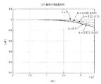
図3は、直線補間の周波数特性の一例を示す図である。なお、この例におけるサンプリング周波数は192kHzである。図3に示すように、bの値に応じて特性はばらついているが、20kHzでの差はほぼ0.5dB以内、10kHzでの差はほぼ0.1dB以内である。この値は、コンテンツの種類によっては十分実用的なレベルである。
【0020】
上述のような直線補間による周波数特性の変動が不都合である場合には、低次のFIR(finite impulse response)形LPFを用いて補間する方法を用いればよい。この低次のFIR型LPFを用いる実施の形態について、図4を参照して説明する。
この実施の形態では、
Y(z)=a0X(z)z−(a−n)+・・・+anX(z)z−a+・・・+a2n+1X(z)z−(a+n+1)
で示されるFIRフィルタを構成し、前記マイクロコンピュータ6は、D1/T1の小数部bに対応したフィルタ係数a0,・・・,an,・・・,a2n+1を与えるようにする。
図4に示した例(a=3,b=0.4)では、3次のラグランジュ補間(n=1)により算出した係数を用い、4タップを使うLPF,
Y(z)=−0.064X(z)z−2+0.672X(z)z−3+0.448X(z)z−4−0.056X(z)z−5
を構成している。
【0021】
図4において、34,35,36及び37は、前記遅延メモリ2のそれぞれ対応するタップの出力に係数を乗算する乗算器、38は前記乗算器34〜37の出力を加算する加算器である。この場合には、4回の乗算と3回の加算で構成される。この実施の形態も掛け算と加算のみで実現され、処理リソースは、入力1ch/出力1スピーカーchあたり、4回の乗加算が必要となる。
ここで、フィルタ係数は、あらかじめポリフェーズフィルタを設計する要領で計算しておき、マイクロコンピュータ6内などに設けられたメモリにテーブルとして持たせておくのが簡単である。図4の例では、1つのフィルタ(1つのbの値)あたり4個の係数が必要なので、時間分解能を64倍にする場合は、256(=64×4)ワードのテーブルとなる。
【0022】
図5は、図4に示した実施の形態の周波数特性を示す図である。ここで、サンプリング周波数は192kHzである。図示するように、20kHzでの差は0.05dB以下、10kHzでの差は0.01dB以下であり、このような低次のFIRフィルタで十分実用に耐えうることがわかる。
なお、3次に限らず、2次や4次のラグランジュ補間を用いてもよい。2次の場合は3つのタップの出力を用い、4次の場合は5つのタップの出力を用いることとなる。
【0023】
図6は、以上説明した各場合における出力波形の一例を示す図である。
この図において、(a)は入力信号X(t)、(b)は前記図11に示した従来技術における出力信号Y(t)=X(t+15μs)、(c)は前記図2に示した直線補間を行なったときの出力信号Y(t)=0.6X(t+15μs)+0.4X(t+20μs)、(d)は前記図4に示したLPF補間を行なったときの出力信号Y(t)=−0.064X(t+10μs)+0.672X(t+15μs)+0.448X(t+20μs)−0.056X(t+25μs)の例をそれぞれ示している。
このように、補間処理によって、理想的な遅延信号(図示する例では、入力を17μs遅らせた信号)を得ることができる。
【0024】
さて、直線補間や低次のLPFによる補間は、図3、図5に見られるように、補間する位置(bの値)によって周波数特性のばらつきが出てしまう。例えば、図3の場合には10kHzでのばらつきが0.1dBとなっている。
一方、アレースピーカーは、扱える上限周波数に限界がある。すなわち、スピーカーユニット間のピッチが出力波長の1/2以上になると、設定する焦点以外の場所にも位相が揃う点が生成されてしまい、ビームが2本以上出ることになってしまう。実用的なスピーカーユニットの直径は2cm程度であり、スピーカーユニットを平面状でハニカムのような互い違いに配置するなどの方法でピッチの実効長を短くすることは可能であるが、この場合でもピッチを2cm以下にすることは困難である。そのため、アレースピーカーで制御できる上限周波数は10kHz以下である。
このように、アレースピーカーの扱える上限周波数は可聴帯域の上限周波数より低く制限されるため、補間する位置による周波数特性のばらつきによる影響はほとんどなく、直線補間や低次のLPFによる補間とアレースピーカーの相性は良いものである。
【0025】
なお、上述した実施の形態においては、前記遅延メモリ2が複数の遅延素子が直列に接続されたシフトレジスタ構成を有するものとして説明したが、これに限られることはなく、サンプリング周期を単位とする遅延出力を得ることができるものであればよい。例えば、ディジタルメモリにサンプリングされた入力信号を書き込み、所定のサンプリング周期経過後に該メモリから信号を読み出すように構成されたものであってもよい。
【0026】
【発明の効果】
以上説明したように、本発明によれば、アレースピーカーの各スピーカーユニット間の遅延時間差を非常に細かい分解能で実現することができる。しかも、アレースピーカーのビーム制御自体に必要なディジタル処理装置のリソースを流用することで実現でき、新たなハードウェアの追加を必要としない。
一方、サンプリング周波数を上げないので、より大きなメモリ,高速処理が可能なD/A変換器やA/D変換器などを必要とせず、高速ディジタル処理が必要とならずに消費電力の増加やコストの増加を防止することができる。
【図面の簡単な説明】
【図1】本発明のアレースピーカーシステムの基本構成を示す図である。
【図2】直線補間を用いる実施の形態の要部構成を示す図である。
【図3】直線補間を用いる実施の形態の周波数特性の例を示す図である。
【図4】LPF補間を用いる実施の形態の要部構成を示す図である。
【図5】LPF補間を用いる実施の形態の周波数特性の例を示す図である。
【図6】各場合における信号波形の例を示す図である。
【図7】アレースピーカーにおける音響信号ビームの制御について説明するための図である。
【図8】アレースピーカーを用いたマルチチャンネル再生について説明するための図である。
【図9】隣接するスピーカーユニット間の遅延時間の差について具体的に説明するための図である。
【図10】従来のアレースピーカー駆動回路の基本構成を示す図である。
【図11】従来のアレースピーカー駆動回路の要部構成を示す図である。
【符号の説明】
1:A/D変換器、2:遅延メモリ、3:補間処理手段、4:D/A変換器、5:スピーカーユニット、6:制御手段、31,32,34〜37:乗算器、33,38:加算器[0001]
TECHNICAL FIELD OF THE INVENTION
The present invention relates to an array speaker system in which a plurality of speaker units are arranged in an array.
[0002]
[Prior art]
It is known to control an acoustic signal beam (directivity) using an array speaker that emits sound by arranging a plurality of speaker units regularly (
Control of directivity in the array speaker will be described with reference to FIG.
In FIG. 7, sp-1 to sp-n are speaker units arranged linearly at predetermined intervals. Here, when generating an acoustic signal beam directed to the focal point indicated by X in the figure, consider an arc Y whose distance from the focal point X is L, and consider the focal point X and each of the speaker units sp-1 to sp-n. Delay time (= Li / sound speed (340 m / s)) according to the distance Li between the intersection of the straight line connecting and the arc Y and the corresponding speaker unit sp-i (i = 1,..., N) To the signal output from the speaker unit sp-i. Thereby, it is possible to control so that the acoustic signals output from the respective speaker units sp-1 to sp-n reach the focal point X at the same time.
As described above, by giving a predetermined delay to the sound signal output from each speaker unit, control is performed so that the sound signal output from each speaker unit simultaneously reaches an arbitrary point (focal point) in space. Accordingly, an effect can be obtained as if an acoustic beam is emitted toward the focal direction.
[0003]
As an application of this technology, it is conceivable to apply several beams to an arbitrary wall in a room and scatter the beams to create a virtual sound source, thereby realizing multi-channel surround.
8, 81 is a listening room, 82 is a video device such as a television, 83 is an array speaker, and 84 is a listener. Here, a description will be given assuming that 5.1-channel reproduction is performed. For the signal of the center channel (C), an acoustic signal is generated forward from the
As described above, the L channel, the R channel, the surround L channel, and the surround R channel are beam-controlled so that the sound signal of the channel is applied to the wall of the listening room by using the
[0004]
In addition, an application in which different contents are provided with different directivities and different contents are listened to on the left and right sides of a room is also considered (Patent Document 3).
[0005]
[Patent Document 1]
Japanese Patent Application Laid-Open No. 03-159500 [Patent Document 2]
JP-A-63-9300 [Patent Document 3]
JP-A-11-27604
[Problems to be solved by the invention]
By performing beam control using an array speaker as described above, multi-channel reproduction, simultaneous reproduction of different contents, and the like can be performed.
However, when controlling the beam of the array speaker, the width of the array must be wide enough to control the signal in the low frequency region, while the signal in the high frequency region is controlled due to the relationship with the sound wavelength. The distance between the speaker units in the array must be sufficiently small to control For example, in order to perform beam control on a signal of 10 kHz, which is an essential band for voice, while sufficiently suppressing side lobes, an interval between speaker units is set to 3.4 cm (= a sound speed of 340 m / s), which is the wavelength of the signal. (10 kHz) or less is ideal. At this time, the difference in delay time between adjacent speaker units becomes very small.
[0007]
This will be specifically described with reference to FIG. FIG. 9 shows adjacent speaker units (spa, spb) for controlling a beam to a focal point X at a distance of 2 m from the front of the array speakers when speaker units constituting the array speakers are arranged at intervals of 3.4 cm. FIGS. 7A and 7B are diagrams illustrating a difference in delay time between the two. FIG. 7A illustrates a case where the focus X is located at a position 1 m away from the speaker unit spb, and FIG.
As shown in the figure, in the case of (a), the distance from the speaker unit spb to the focal point X is 2.2361 m, the distance between the speaker unit spa adjacent to the speaker unit spb and the focal point X is 2.2515 m, The difference between the delay times is (2.2515-2.2316) m ÷ 340 m / s = 45 μs. Assuming that the amount of delay given to the signal output to the speaker unit spa is ta, the delay added to the output of spb is (ta + 45 μs). In the case of (b), the distance from the speaker unit spb to the focal point X is 2 m, the distance from the speaker unit spa to the focal point X is 2.0003 m, and the difference between the delay times is 0.0003 m ÷ 340 m / s. = 0.9 μs. In this case, the delay given to the output of the speaker unit spb is (ta + 0.9 μs).
As described above, the difference between the delay times of the adjacent speaker units varies depending on the position of the focal point X, but is a very small value from several tens of microseconds to 1 microsecond or less.
[0008]
FIG. 10 is a diagram illustrating a basic configuration of a delay control circuit (beam control circuit) of an array speaker that applies a delay corresponding to a signal supplied to each speaker unit. Here, only a circuit that handles one channel output, that is, only one beam is shown. When the number of channels (number of beams) becomes plural, the signal can be easily expanded by adding signals of a plurality of channels with delays before D / A conversion for each speaker unit. is there.
10,
[0009]
In the delay control circuit thus configured, an analog input signal is converted into a digital signal by the A /
[0010]
As described above, the delay of the signal supplied to each speaker unit is created by the
FIG. 11 is a diagram showing the
Here, assuming that the delay time to be added is D1 and the sampling period is T1, the number of taps for delay can be obtained from D1 / T1.
The microcomputer 96 (FIG. 10) calculates a distance from the focal point X to each speaker unit, calculates a delay time given to a signal to each speaker unit, and uses the calculated delay time as the number of delay taps of the
When b> 0.5, Y (z) = X (z) z −a ,
When b ≧ 0.5, Y (z) = X (z) z− (a + 1)
It becomes.
Assuming that the sampling frequency Fs is 200 kHz (sampling period T1 = 5 μs) and the delay D1 to be applied is 17 μs, a = 3, b = 0.4, b <0.5 from 17/5 = 3.4. Thus, Y (z) = X (z) z− 3 .
That is, a signal having a delay time of 15 μs is taken out from the tap of the delay element 92-3, and an error of 2 μs occurs.
Thus, if the sampling frequency Fs is assumed to be 200 kHz, the minimum value of the delay time is 5 μs, and it cannot be said that the above-described delay time difference between the speakers can be sufficiently expressed.
[0011]
To increase the delay resolution, the sampling frequency Fs may be increased, but a larger memory is required to obtain the same amount of delay, and a D / A converter or an A / D converter capable of high-speed processing is required. In addition, high-speed digital processing is required, making design difficult, increasing power consumption, and increasing costs. In addition, when digital signal processing such as digital filtering is performed, there are many disadvantages such as a larger number of taps (the number of operations) is required to achieve the same characteristics.
[0012]
Therefore, an object of the present invention is to provide an array speaker system that can control the directivity of an acoustic signal by an array speaker with high accuracy without increasing a sampling frequency.
[0013]
[Means for Solving the Problems]
In order to achieve the above object, the array speaker system of the present invention controls the directivity of an acoustic signal by outputting a signal with a time difference corresponding to each from a plurality of speaker units arranged in an array. An array speaker system configured as described above, comprising: a delay memory for delaying an audio signal in units of a sampling period; a control unit for calculating a delay amount given to a signal to each speaker unit; and a delay amount calculated by the control unit. And an interpolation processing means for performing an interpolation processing on the output from the delay memory based on the above-mentioned method, and the output of the interpolation processing means is supplied to each of the speaker units.
Further, the interpolation processing means is means for performing linear interpolation.
Alternatively, an FIR low-pass filter is constituted by the delay memory and the interpolation processing means.
[0014]
BEST MODE FOR CARRYING OUT THE INVENTION
FIG. 1 is a diagram showing a basic configuration of a delay control circuit (beam control circuit) in the array speaker system of the present invention. Here, a circuit that handles only one channel output (one beam) is described. When the number of channels becomes more than one, the signals can be easily expanded by adding signals of a plurality of channels with delays for each speaker unit before A / D conversion, as described above. Can be.
In this figure, 1 is an A / D converter for converting an input signal of this channel into a digital signal, 2 is a delay memory for delaying the input digital signal in sampling period units and outputting from a corresponding tap, 3 is Interpolation processing means 4 for outputting a signal with a delay given to a signal to each speaker unit using the output of the corresponding tap of the
[0015]
As described above, in the array speaker system of the present invention, since the delay amount given to the signal to each speaker unit is obtained by interpolation, high-accuracy directivity control can be performed without increasing the sampling frequency. Becomes possible.
[0016]
A specific embodiment of the interpolation processing means 3 will be further described.
FIG. 2 is a diagram showing a basic configuration of an embodiment in which the interpolation calculation means 3 performs linear interpolation. Here, a delay control circuit corresponding to one speaker unit (N-th speaker unit) 5 is shown.
In the drawing, 2-1 to 2-2,..., 2-5,... Denote delay elements that move data at a sampling period, and the
[0017]
As described above, when the delay to be added is D1 and the sampling period is T1, the number of taps for the delay can be obtained from D1 / T1. In this embodiment, if the calculation result of D1 / T1 is represented by (a + b) of an integer part a and a decimal part b,
With linear interpolation,
Y (z) = (1-b) X (z) z- a + bX (z) z- (a + 1)
The coefficient b and (1-b) are set so that
As in the case of FIG. 11, assuming that the sampling period T1 = 5 μs and the delay D1 to be applied is 17 μs, FIG. 2 is obtained from 17/5 = 3.4, a = 3, b = 0.4. like,
Y (z) = 0.6X (z) z- 3 + 0.4X (z) z- 4
It becomes.
As described above, signals are taken out from the two nearest taps sandwiching the delay amount to be given, and weighted below the decimal point, and an interpolation signal is calculated.
[0018]
The processing required for interpolation is only multiplication and addition, except for the calculation of coefficients by the
[0019]
The good point of such linear interpolation is that, with simple processing, the time accuracy (resolution) becomes infinite (if the coefficient word length of the processor is ignored).
However, on the other hand, as can be seen from the above equation, the linear interpolation works as a low-pass filter (LPF: Low Pass Filter). In addition, when the coefficient b and (1-b) change, the frequency characteristic changes.
FIG. 3 is a diagram illustrating an example of a frequency characteristic of linear interpolation. Note that the sampling frequency in this example is 192 kHz. As shown in FIG. 3, although the characteristics vary depending on the value of b, the difference at 20 kHz is within approximately 0.5 dB, and the difference at 10 kHz is within approximately 0.1 dB. This value is a sufficiently practical level depending on the type of content.
[0020]
When the fluctuation of the frequency characteristic due to the linear interpolation as described above is inconvenient, a method of performing interpolation using a low-order FIR (fine impulse response) LPF may be used. An embodiment using this low-order FIR LPF will be described with reference to FIG.
In this embodiment,
Y (z) = a 0 X (z) z - (a-n) + ··· + a n X (z) z -a + ··· + a 2n + 1 X (z) z - (a + n + 1)
, And the
In the example shown in FIG. 4 (a = 3, b = 0.4), an LPF using four taps using coefficients calculated by third-order Lagrange interpolation (n = 1),
Y (z) = − 0.064X (z) z− 2 + 0.672X (z) z− 3 + 0.448X (z) z − 4−0.056X (z) z− 5
Is composed.
[0021]
In FIG. 4,
Here, it is easy to calculate the filter coefficients in advance in the manner of designing a polyphase filter, and to store them as a table in a memory provided in the
[0022]
FIG. 5 is a diagram showing frequency characteristics of the embodiment shown in FIG. Here, the sampling frequency is 192 kHz. As shown in the figure, the difference at 20 kHz is 0.05 dB or less, and the difference at 10 kHz is 0.01 dB or less, indicating that such a low-order FIR filter can sufficiently withstand practical use.
Note that not only the third order but also the second or fourth order Lagrange interpolation may be used. In the case of the second order, the output of three taps is used, and in the case of the fourth order, the output of five taps is used.
[0023]
FIG. 6 is a diagram illustrating an example of an output waveform in each case described above.
In this figure, (a) is the input signal X (t), (b) is the output signal Y (t) = X (t + 15 μs) in the prior art shown in FIG. 11, and (c) is the one shown in FIG. Output signal Y (t) when performing linear interpolation = 0.6X (t + 15 μs) + 0.4X (t + 20 μs), and (d) shows output signal Y (t) when performing LPF interpolation shown in FIG. = −0.064 × (t + 10 μs) + 0.672 × (t + 15 μs) + 0.448 × (t + 20 μs) −0.056 × (t + 25 μs).
As described above, an ideal delay signal (a signal whose input is delayed by 17 μs in the illustrated example) can be obtained by the interpolation processing.
[0024]
By the way, in the linear interpolation or the interpolation by the low-order LPF, as shown in FIGS. 3 and 5, the frequency characteristics vary depending on the position (the value of b) to be interpolated. For example, in the case of FIG. 3, the variation at 10 kHz is 0.1 dB.
On the other hand, array speakers have a limit on the upper limit frequency that can be handled. That is, when the pitch between the speaker units is equal to or more than 1 / of the output wavelength, a point where the phases are aligned at a place other than the set focal point is generated, and two or more beams are emitted. The diameter of a practical speaker unit is about 2 cm, and it is possible to shorten the effective length of the pitch by, for example, arranging the speaker units in a plane and alternately like a honeycomb. It is difficult to make it less than 2 cm. Therefore, the upper limit frequency that can be controlled by the array speaker is 10 kHz or less.
As described above, since the upper limit frequency that the array speaker can handle is limited to be lower than the upper limit frequency of the audible band, there is almost no influence due to the variation in the frequency characteristic depending on the position to be interpolated. The compatibility is good.
[0025]
In the above-described embodiment, the
[0026]
【The invention's effect】
As described above, according to the present invention, a delay time difference between each speaker unit of an array speaker can be realized with a very fine resolution. Moreover, this can be realized by diverting the resources of the digital processing device necessary for the beam control of the array speaker itself, and does not require the addition of new hardware.
On the other hand, since the sampling frequency is not increased, a larger memory, a D / A converter or an A / D converter capable of high-speed processing are not required, and high-speed digital processing is not required, thereby increasing power consumption and cost. Can be prevented from increasing.
[Brief description of the drawings]
FIG. 1 is a diagram showing a basic configuration of an array speaker system of the present invention.
FIG. 2 is a diagram showing a main configuration of an embodiment using linear interpolation.
FIG. 3 is a diagram illustrating an example of a frequency characteristic of an embodiment using linear interpolation.
FIG. 4 is a diagram showing a main configuration of an embodiment using LPF interpolation.
FIG. 5 is a diagram illustrating an example of a frequency characteristic of an embodiment using LPF interpolation.
FIG. 6 is a diagram illustrating an example of a signal waveform in each case.
FIG. 7 is a diagram for describing control of an acoustic signal beam in an array speaker.
FIG. 8 is a diagram for explaining multi-channel reproduction using an array speaker.
FIG. 9 is a diagram for specifically explaining a difference in delay time between adjacent speaker units.
FIG. 10 is a diagram showing a basic configuration of a conventional array speaker drive circuit.
FIG. 11 is a diagram showing a main part configuration of a conventional array speaker drive circuit.
[Explanation of symbols]
1: A / D converter, 2: delay memory, 3: interpolation processing means, 4: D / A converter, 5: speaker unit, 6: control means, 31, 32, 34 to 37: multiplier, 33, 38: Adder
Claims (3)
音響信号をサンプリング周期単位で遅延させる遅延メモリと、
各スピーカーユニットへの信号に与える遅延量を算出する制御手段と、
前記制御手段により算出された遅延量に基づき、前記遅延メモリからの出力に対する補間処理を行なう補間処理手段とを有し、
前記補間処理手段の出力を前記各スピーカーユニットに供給するようになされていることを特徴とするアレースピーカーシステム。An array speaker system adapted to control the directivity of an acoustic signal by outputting a signal to which a time difference corresponding to each is provided from a plurality of speaker units arranged in an array,
A delay memory for delaying an audio signal in units of a sampling period;
Control means for calculating an amount of delay given to a signal to each speaker unit;
Based on the delay amount calculated by the control means, an interpolation processing means for performing interpolation processing on the output from the delay memory,
An array speaker system, wherein an output of the interpolation processing means is supplied to each of the speaker units.
Priority Applications (5)
| Application Number | Priority Date | Filing Date | Title |
|---|---|---|---|
| JP2003156767A JP4007255B2 (en) | 2003-06-02 | 2003-06-02 | Array speaker system |
| CN2004800150022A CN1799283B (en) | 2003-06-02 | 2004-06-01 | Array speaker system |
| US10/558,945 US7397923B2 (en) | 2003-06-02 | 2004-06-01 | Array speaker system |
| EP04745630A EP1631119B1 (en) | 2003-06-02 | 2004-06-01 | Array speaker system |
| PCT/JP2004/007917 WO2004107812A1 (en) | 2003-06-02 | 2004-06-01 | Array speaker system |
Applications Claiming Priority (1)
| Application Number | Priority Date | Filing Date | Title |
|---|---|---|---|
| JP2003156767A JP4007255B2 (en) | 2003-06-02 | 2003-06-02 | Array speaker system |
Publications (2)
| Publication Number | Publication Date |
|---|---|
| JP2004363696A true JP2004363696A (en) | 2004-12-24 |
| JP4007255B2 JP4007255B2 (en) | 2007-11-14 |
Family
ID=33487386
Family Applications (1)
| Application Number | Title | Priority Date | Filing Date |
|---|---|---|---|
| JP2003156767A Expired - Fee Related JP4007255B2 (en) | 2003-06-02 | 2003-06-02 | Array speaker system |
Country Status (5)
| Country | Link |
|---|---|
| US (1) | US7397923B2 (en) |
| EP (1) | EP1631119B1 (en) |
| JP (1) | JP4007255B2 (en) |
| CN (1) | CN1799283B (en) |
| WO (1) | WO2004107812A1 (en) |
Cited By (6)
| Publication number | Priority date | Publication date | Assignee | Title |
|---|---|---|---|---|
| JP2010213135A (en) * | 2009-03-12 | 2010-09-24 | Kenwood Corp | Sound quality adjusting apparatus |
| JP2010539833A (en) * | 2007-09-19 | 2010-12-16 | フラウンホッファー−ゲゼルシャフト ツァ フェルダールング デァ アンゲヴァンテン フォアシュンク エー.ファオ | Apparatus and method for determining component signals with high accuracy |
| US8045736B2 (en) | 2006-12-01 | 2011-10-25 | Fujitsu Ten Limited | Sound field reproduction system |
| WO2011135646A1 (en) * | 2010-04-26 | 2011-11-03 | ティーオーエー株式会社 | Speaker device and filter coefficient generation device therefor |
| US8302571B2 (en) | 2006-12-12 | 2012-11-06 | Toyota Jidosha Kabushiki Kaisha | Air to fuel ratio control device |
| EP3232688A1 (en) | 2016-04-12 | 2017-10-18 | Fraunhofer-Gesellschaft zur Förderung der angewandten Forschung e.V. | Apparatus and method for providing individual sound zones |
Families Citing this family (14)
| Publication number | Priority date | Publication date | Assignee | Title |
|---|---|---|---|---|
| JP4214834B2 (en) * | 2003-05-09 | 2009-01-28 | ヤマハ株式会社 | Array speaker system |
| JP4007254B2 (en) * | 2003-06-02 | 2007-11-14 | ヤマハ株式会社 | Array speaker system |
| JP3876850B2 (en) * | 2003-06-02 | 2007-02-07 | ヤマハ株式会社 | Array speaker system |
| JP4449998B2 (en) * | 2007-03-12 | 2010-04-14 | ヤマハ株式会社 | Array speaker device |
| JP4488036B2 (en) * | 2007-07-23 | 2010-06-23 | ヤマハ株式会社 | Speaker array device |
| KR101476139B1 (en) * | 2007-11-28 | 2014-12-30 | 삼성전자주식회사 | Method and apparatus for generating the sound source signal using the virtual speaker |
| JP5577597B2 (en) * | 2009-01-28 | 2014-08-27 | ヤマハ株式会社 | Speaker array device, signal processing method and program |
| KR101423111B1 (en) * | 2010-08-10 | 2014-07-30 | 창원대학교 산학협력단 | Band pass sampling receiver |
| CA3079257C (en) * | 2010-10-21 | 2022-10-25 | Acoustic 3D Holdings Limited | Acoustic diffusion generator |
| TWI590674B (en) | 2012-11-02 | 2017-07-01 | Amazing Microelectronic Corp | Flat loudspeaker output device and its method of starting a flat loudspeaker |
| JP5882403B2 (en) * | 2014-06-25 | 2016-03-09 | 株式会社カプコン | Sound effect processing program and game device |
| USRE49437E1 (en) | 2014-09-30 | 2023-02-28 | Apple Inc. | Audio driver and power supply unit architecture |
| US10652650B2 (en) | 2014-09-30 | 2020-05-12 | Apple Inc. | Loudspeaker with reduced audio coloration caused by reflections from a surface |
| US10834497B2 (en) | 2016-09-23 | 2020-11-10 | Apple Inc. | User interface cooling using audio component |
Family Cites Families (26)
| Publication number | Priority date | Publication date | Assignee | Title |
|---|---|---|---|---|
| NL8001119A (en) | 1980-02-25 | 1981-09-16 | Philips Nv | DIRECTIONAL INDEPENDENT SPEAKER COLUMN OR SURFACE. |
| US4544927A (en) * | 1982-11-04 | 1985-10-01 | Sperry Corporation | Wideband beamformer |
| JPS639300A (en) | 1986-06-27 | 1988-01-14 | Matsushita Electric Ind Co Ltd | Speaker system |
| US5146507A (en) * | 1989-02-23 | 1992-09-08 | Yamaha Corporation | Audio reproduction characteristics control device |
| JP3067140B2 (en) | 1989-11-17 | 2000-07-17 | 日本放送協会 | 3D sound reproduction method |
| JPH04127700A (en) | 1990-09-18 | 1992-04-28 | Matsushita Electric Ind Co Ltd | Image controller |
| JPH0541897A (en) * | 1991-08-07 | 1993-02-19 | Pioneer Electron Corp | Speaker equipment and directivity control method |
| JPH05103391A (en) | 1991-10-07 | 1993-04-23 | Matsushita Electric Ind Co Ltd | Directivity-controlled loudspeaker system |
| EP0563929B1 (en) * | 1992-04-03 | 1998-12-30 | Yamaha Corporation | Sound-image position control apparatus |
| JP3322694B2 (en) | 1992-05-25 | 2002-09-09 | 株式会社日立メディコ | Ultrasound imaging device |
| JP3205625B2 (en) | 1993-01-07 | 2001-09-04 | パイオニア株式会社 | Speaker device |
| GB9506725D0 (en) | 1995-03-31 | 1995-05-24 | Hooley Anthony | Improvements in or relating to loudspeakers |
| US5809150A (en) * | 1995-06-28 | 1998-09-15 | Eberbach; Steven J. | Surround sound loudspeaker system |
| JP3826423B2 (en) | 1996-02-22 | 2006-09-27 | ソニー株式会社 | Speaker device |
| JPH09322299A (en) * | 1996-05-24 | 1997-12-12 | Victor Co Of Japan Ltd | Sound image localization controller |
| FI105522B (en) * | 1996-08-06 | 2000-08-31 | Sample Rate Systems Oy | Arrangement for home theater or other audio equipment |
| US5789689A (en) * | 1997-01-17 | 1998-08-04 | Doidic; Michel | Tube modeling programmable digital guitar amplification system |
| JPH10304500A (en) | 1997-04-25 | 1998-11-13 | Victor Co Of Japan Ltd | Sound field reproducing device |
| JPH1127604A (en) | 1997-07-01 | 1999-01-29 | Sanyo Electric Co Ltd | Audio reproducing device |
| US6546105B1 (en) * | 1998-10-30 | 2003-04-08 | Matsushita Electric Industrial Co., Ltd. | Sound image localization device and sound image localization method |
| JP2000267675A (en) * | 1999-03-16 | 2000-09-29 | Sega Enterp Ltd | Acoustical signal processor |
| JP5306565B2 (en) | 1999-09-29 | 2013-10-02 | ヤマハ株式会社 | Acoustic directing method and apparatus |
| JP4196509B2 (en) * | 1999-12-27 | 2008-12-17 | ソニー株式会社 | Sound field creation device |
| US7003124B1 (en) * | 2000-05-30 | 2006-02-21 | Thiel Audio Products | System and method for adjusting frequency response characteristics of high-pass crossovers supplying signal to speakers used with subwoofers |
| KR100922910B1 (en) | 2001-03-27 | 2009-10-22 | 캠브리지 메카트로닉스 리미티드 | Method and apparatus to create a sound field |
| US7116788B1 (en) * | 2002-01-17 | 2006-10-03 | Conexant Systems, Inc. | Efficient head related transfer function filter generation |
-
2003
- 2003-06-02 JP JP2003156767A patent/JP4007255B2/en not_active Expired - Fee Related
-
2004
- 2004-06-01 US US10/558,945 patent/US7397923B2/en active Active
- 2004-06-01 EP EP04745630A patent/EP1631119B1/en not_active Expired - Fee Related
- 2004-06-01 CN CN2004800150022A patent/CN1799283B/en not_active Expired - Fee Related
- 2004-06-01 WO PCT/JP2004/007917 patent/WO2004107812A1/en active Application Filing
Cited By (10)
| Publication number | Priority date | Publication date | Assignee | Title |
|---|---|---|---|---|
| US8045736B2 (en) | 2006-12-01 | 2011-10-25 | Fujitsu Ten Limited | Sound field reproduction system |
| US8302571B2 (en) | 2006-12-12 | 2012-11-06 | Toyota Jidosha Kabushiki Kaisha | Air to fuel ratio control device |
| JP2010539833A (en) * | 2007-09-19 | 2010-12-16 | フラウンホッファー−ゲゼルシャフト ツァ フェルダールング デァ アンゲヴァンテン フォアシュンク エー.ファオ | Apparatus and method for determining component signals with high accuracy |
| US8526623B2 (en) | 2007-09-19 | 2013-09-03 | Fraunhofer-Gesellschaft Zur Foerderung Der Angewandten Forschung E.V. | Device and a method for determining a component signal with high accuracy |
| JP2010213135A (en) * | 2009-03-12 | 2010-09-24 | Kenwood Corp | Sound quality adjusting apparatus |
| WO2011135646A1 (en) * | 2010-04-26 | 2011-11-03 | ティーオーエー株式会社 | Speaker device and filter coefficient generation device therefor |
| JP5709849B2 (en) * | 2010-04-26 | 2015-04-30 | Toa株式会社 | Speaker device and filter coefficient generation device thereof |
| US9118997B2 (en) | 2010-04-26 | 2015-08-25 | TOA Coporation | Speaker device and filter coefficient generating device therefor |
| EP3232688A1 (en) | 2016-04-12 | 2017-10-18 | Fraunhofer-Gesellschaft zur Förderung der angewandten Forschung e.V. | Apparatus and method for providing individual sound zones |
| WO2017178454A1 (en) | 2016-04-12 | 2017-10-19 | Fraunhofer-Gesellschaft zur Förderung der angewandten Forschung e.V. | Apparatus and method for providing individual sound zones |
Also Published As
| Publication number | Publication date |
|---|---|
| CN1799283B (en) | 2012-08-29 |
| WO2004107812A1 (en) | 2004-12-09 |
| EP1631119A1 (en) | 2006-03-01 |
| CN1799283A (en) | 2006-07-05 |
| US20070030976A1 (en) | 2007-02-08 |
| EP1631119B1 (en) | 2012-02-01 |
| JP4007255B2 (en) | 2007-11-14 |
| US7397923B2 (en) | 2008-07-08 |
Similar Documents
| Publication | Publication Date | Title |
|---|---|---|
| JP4007255B2 (en) | Array speaker system | |
| US7515719B2 (en) | Method and apparatus to create a sound field | |
| CA2325482A1 (en) | Audio signal processing method and apparatus | |
| JPH05265477A (en) | Sound field correcting device | |
| Wu et al. | FPGA-based implementation of steerable parametric loudspeaker using fractional delay filter | |
| EP1929838B1 (en) | Method and apparatus to generate spatial sound | |
| JPH06269098A (en) | Sound field control system | |
| JPH0990967A (en) | Digital filter and acoustic reproducing device | |
| JP4915079B2 (en) | Sound reproduction system | |
| JPH1188994A (en) | Sound image presence device and sound image control method | |
| KR100886932B1 (en) | Multi Channel Beamformer using Single Interpolation | |
| JP2010213135A (en) | Sound quality adjusting apparatus | |
| JP2013016908A (en) | Sine wave generator, digital signal processor, and audio output device | |
| JP3821417B2 (en) | Reverberation equipment | |
| JPS609212A (en) | Acoustic reproducer | |
| JP2006323395A (en) | Signal processing apparatus and sound reproducing apparatus | |
| JPH06130942A (en) | Acoustic effect device | |
| JP2905904B2 (en) | Electronic musical instrument signal processor | |
| JP5466054B2 (en) | D / A converter | |
| JPS646414B2 (en) | ||
| JP2006067310A (en) | Stereophonic sound reproducing apparatus and reproducing program | |
| JP2000308199A (en) | Signal processor and manufacture of signal processor | |
| JP2000307385A (en) | Frequency divider circuit | |
| JPH04167700A (en) | Sympathetic sound adding device | |
| JPS6321916B2 (en) |
Legal Events
| Date | Code | Title | Description |
|---|---|---|---|
| A621 | Written request for application examination |
Free format text: JAPANESE INTERMEDIATE CODE: A621 Effective date: 20050728 |
|
| A131 | Notification of reasons for refusal |
Free format text: JAPANESE INTERMEDIATE CODE: A131 Effective date: 20061010 |
|
| A521 | Request for written amendment filed |
Free format text: JAPANESE INTERMEDIATE CODE: A523 Effective date: 20061207 |
|
| TRDD | Decision of grant or rejection written | ||
| A01 | Written decision to grant a patent or to grant a registration (utility model) |
Free format text: JAPANESE INTERMEDIATE CODE: A01 Effective date: 20070807 |
|
| A61 | First payment of annual fees (during grant procedure) |
Free format text: JAPANESE INTERMEDIATE CODE: A61 Effective date: 20070820 |
|
| FPAY | Renewal fee payment (event date is renewal date of database) |
Free format text: PAYMENT UNTIL: 20100907 Year of fee payment: 3 |
|
| R150 | Certificate of patent or registration of utility model |
Ref document number: 4007255 Country of ref document: JP Free format text: JAPANESE INTERMEDIATE CODE: R150 |
|
| FPAY | Renewal fee payment (event date is renewal date of database) |
Free format text: PAYMENT UNTIL: 20100907 Year of fee payment: 3 |
|
| FPAY | Renewal fee payment (event date is renewal date of database) |
Free format text: PAYMENT UNTIL: 20110907 Year of fee payment: 4 |
|
| FPAY | Renewal fee payment (event date is renewal date of database) |
Free format text: PAYMENT UNTIL: 20120907 Year of fee payment: 5 |
|
| FPAY | Renewal fee payment (event date is renewal date of database) |
Free format text: PAYMENT UNTIL: 20130907 Year of fee payment: 6 |
|
| LAPS | Cancellation because of no payment of annual fees |