【0001】
【発明の属する技術分野】
本発明は、エキシマ光を照射するエキシマランプの調光方法及び該エキシマランプを用いたエキシマ光源装置に関し、更に詳しくはランプ管軸方向にエキシマ光を照射することを目的としたいわゆるヘッドオン型のエキシマランプ及び該エキシマランプを配置したエキシマ光源装置の調光を可能にする装置に関する。
【0002】
【従来の技術】
近年、半導体製造プロセスにおける洗浄工程や液晶基板の洗浄工程等に波長200nm以下の真空紫外光を放射する真空紫外光照射装置が広く用いられている。この真空紫外光照射装置に配置される光源としては、希ガスや、希ガスとハロゲンガスとの混合ガスが封入され、このガス中の放電により生成したエキシマ分子が低エネルギー準位に遷移する過程で放射されるエキシマ光を利用した、いわゆるエキシマランプが多く用いられている。このような光源を利用した装置は一般的にエキシマ光源装置と呼ばれている。
【0003】
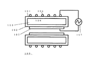
該装置に用いられる従来のエキシマランプの代表的な構成を図7に概略断面図として示す。該エキシマランプ100は石英ガラスなどの光透過性部材によって構成された外側管101と内側管102とからなる放電容器103と、該外側管101の外壁に配置された金属網等からなる光透過性の第1の電極104と、該内側管102の内壁に配置されたアルミニウム板等からなる第2の電極105とから成っている。該放電容器103の内部には放電用ガス106として、例えばキセノンガス等の希ガスや、希ガスとハロゲンガスとの混合ガスが封入されている。また、該第1の電極104と該第2の電極105との間には高周波高電圧電源107が接続されており、数十kHzの高周波高電圧を付加し該放電容器103内に放電を発生させている。該放電により該放電用ガス106のエキシマ分子が生成され、このエキシマ分子が低エネルギー準位に遷移する過程でエキシマ光が放射される。該エキシマランプ100における光放射方向は、該第1の電極104の配置されたランプ側面方向であり、大面積の照射用に該エキシマランプ100を複数本並列配置したものが多く用いられている。
【0004】
図8に該エキシマランプ100を複数本並列配置した従来のエキシマ光源装置の概略図を示す。該エキシマ光源装置200には、該エキシマランプ100が複数本配置されたランプハウス201と該ランプハウス201と被照射物202との間に配置された石英ガラス製の窓部203が設けられ、該ランプハウス201内を窒素パージする窒素導入口204と窒素排出口205とを備えている。また、該エキシマランプ201から放射されるエキシマ光を反射する反射鏡206が該窓部203に対向する方向に配置されている。
【0005】
ところで、前記のエキシマランプ100、を複数本並べ該エキシマランプから放射される真空紫外光による洗浄等の表面処理は、非常に複雑で高度な光化学反応を利用したものである。該表面処理において期待する表面処理効果を得るためには、照射エネルギー量に過不足があってはならない。照射エネルギー量が不足している場合には、光化学反応が完遂されず問題であることは明らかであるが、照射エネルギー量が過剰である場合も問題となる。たとえば、光化学反応により生成された物質が更に化学変化を起こしてしまうとか、所望の表面深さ以上まで光化学反応を起こしてしまうといった問題が生じる。したがって精確な表面処理を行うためには、被処理物に均一で一定量のエネルギー照射が必要であり、エキシマ光源装置には照射エネルギー量を精確に制御できる機能が求められる。
【0006】
被処理物に照射される照射エネルギー量は、光源装置からの単位時間当たりの照射エネルギー量と照射時間の積により決定される。この照射エネルギー量を制御する方法には2通りある。第1の方法は、照射時間を制御する方法であり、第2の方法は単位時間当たりの照射エネルギー量を制御する方法である。しかし、第1の方法である照射時間を制御する方法の方が簡単に照射エネルギー量を制御することができるが用途が限定されるといった欠点を有する。たとえば照射方法が枚葉式であれば、照射時のエネルギー量をモニターすることにより照射時間を制御すれば良いが、連続的に搬送されるものに照射する場合には時間制御は困難となる。そこで、通常は第2の方法として示した単位時間当たりの照射エネルギー量を制御する方法が有用であり、該エキシマ光源装置には、単位時間当たりの照射エネルギー量を制御する機能を備えることが望ましい。単位時間当たりの照射エネルギー量を制御するためには該エキシマランプそれ自身を調光することが行われており種々の調光手段が提案されている。
【0007】
最も簡単な調光手段としてはエキシマランプに印加する電力を調整する方法が考えられる。しかしながら、この方法では調光下限は50%程度であり調光範囲が狭いという欠点が有るので実使用上では問題となる。この下限値は、以下のような理由から生じている。ランプ材料の寸法精度および加工精度のバラツキにより、1個のエキシマランプ内に少なくない寸法上の不均一が生じている。この不均一により、エキシマランプ内に発光強度分布が生じるが、エキシマランプに定格電力を印加しているような状況では発光強度分布が目立たず問題とはならない。しかし減光するためにエキシマランプに印加する電力を徐々に減少させると、初めは発光強度がエキシマランプ全体にわたり減少するが、エキシマランプに印加されている電圧が放電維持電圧付近にまで減少すると、エキシマランプ内の寸法不均一等に起因する放電維持電圧の不均一さのため、放電が維持されている個所と放電が維持されず消えている個所の分布が生じてしまう。その結果、均一なエキシマ光照射処理が不可能となるため、該不均一放電が発生する場合の入力電圧値が調光可能の下限値となる。この下限値よりさらにエキシマランプに印加する電力を低減すると、ランプ内のすべての個所で放電維持電圧を維持できなくなり一気に放電が消滅してしまう。このようにエキシマランプの調光に電力を可変する方法は適していなかった。また、ランプ端部に設けられた照射窓からランプ管軸方向に光を放射するヘッドオン型エキシマランプにおいても、点灯周波数が数10kHzから数100kHzの高周波高電圧で該電力調光を行うと、放射される光のチラツキが発生する。特に入力電力が定格点灯の50%程度以下になると管軸方向のみならず円筒管の円周方向でも放電する場所としない場所とが発生し、結果として照射される光が不均一となる。更に入力電力を下げると前述の場合と同様にランプ内のすべての個所で放電維持電圧を維持できなくなり一気に放電が消滅してしまう。このように電力調光は該エキシマランプの調光には適していなかった。
【0008】
上述した電力による調光での問題を解決する手段としては、例えば特開平10−097898号公報に開示されている。該公報によれば、ランプに印加する瞬時電力を下げる方法(以下、「電力調光」と呼ぶ)ではなく、図9−(b)に示すように印加する時間を減少させる手段により、ランプに入力される平均電力を下げる調光方法、いわゆるバースト調光が示されている。図9は縦軸にランプに印加する電圧、横軸に時間をとった図であり、(a)は電力調光の場合、(b)はバースト調光の場合の該エキシマランプに入力する印加電圧を表したものである。それぞれ、時間t1までは100%の入力電力で点灯されているが、t1の時点から調光を開始している。図9−(b)のバースト調光の場合は、該エキシマランプに印加されている数10kHzから数100kHzの高周波高電圧に、低い周波数のパルスを加えon−offの期間を設け、またそのパルスのon−offの比を変えるといったものである。
【0009】
この調光方法により、調光可能な範囲は飛躍的に増大し、事実上0%〜100%までの調光が可能になった。しかし、該バースト調光による調光方法では非常に複雑な制御回路が必要となるため、エキシマ光源装置の大型化やコスト増加といった問題が有った。
【0010】
【特許文献1】
特開平10−097898号公報
【0011】
【発明が解決しようとする課題】
エキシマランプから放射されるエキシマ光の調光範囲を狭めることなく、電力を可変することで安定した調光が可能なエキシマランプを提供することを目的とする。更には、小型で簡単な制御回路により調光可能なエキシマ光源装置を提供することを目的とする。
【0012】
【課題を解決するための手段】
本発明者らは、エキシマランプに印加する電力を数MHz以上の高周波電力として印加し、更に、該エキシマランプの入力を定格電力から減少させると、図10に示すように放電体積が連続的に減少するといった現象を新しく見出した。図10は、エキシマランプ60に数MHzの高周波電力を入力した場合の放電領域を示す概略図である。図10−(a)、(b)は該エキシマランプ60を定格電力のそれぞれ20%、50%に減少させた場合の放電領域を示したものであり、放電領域は縮小して放電管の給電線接続側に偏在した放電プラズマ61となっている。また、図10−(c)は該エキシマランプ60に定格電力を入力した場合の放電領域を示しており、定格電力では放電管全域にわたって放電プラズマ61が発生している。
【0013】
入力電圧を低下させた時このような放電の縮小が発生するのは、ランプに印加する周波数を増加させたことで、電極内での電圧分布が無視できなくなったためであると考えられる。しかし、ランプ側面方向から光を取り出すエキシマランプでは該放電の縮小によって被照射物への光照射範囲が変動するため均一な照射ができないばかりか、縮小した放電にさらされる放電管自身の劣化により定格電力で駆動しても長い点灯時間後には均一な照射ができないことになる。そこで、入力電力を減少させると管軸方向に放電が収縮するといった現象を光放射方向がランプ管軸方向であるいわゆるヘッドオン型の該エキシマランプに適用することで被照射物への均一な照射を実現すると伴に幅広い調光を可能とした。つまり、放電容器の一部で発生したエキシマ光がランプ管軸方向に渡って積分され該放電容器の端部である光放射窓から放射されるヘッドオン型エキシマランプにおいて広い範囲の調光が可能となる。
【0014】
具体的な本発明のエキシマランプの構成は、石英ガラスから成る二重円筒型の放電容器と、該放電容器の外側管の外壁に形成された第1の電極と該内側管の内側に形成された第2の電極と、該第2の電極に電力供給する給電線と、該放電容器の管軸方向端部に形成された光取り出し窓と、から成り、高周波高電圧を発生する電源に該給電線を介して接続されたヘッドオン型のエキシマランプにおいて、該エキシマランプの点灯周波数をMHz帯域で点灯し、点灯時の入力電力を可変にすることにより光出力を調光可能としたことを特徴とする。ここでMHz帯域とは、具体的には1MHz乃至999MHzを言う。1MHz以下だと、うまく放電がアンテナ付近に残らず放電発生箇所が一定とならないため安定した照射ができない。また、1GHz以上だと、アンテナに電磁波が吸収されてしまい、放電自身が生成されないといった不具合を生じる。
【0015】
該構成により、簡易な回路構成で0%から100%まで調光可能にしたエキシマランプを提供できるといった利点がある。
前記のMHz帯域の高周波高電圧を発生する電源としては、例えば水晶発振子を用いた回路がある。図11に高周波高電圧電源を説明するブロック図を示す。高周波高電圧を供給する電源71は、水晶発信子からなる所定の周波数信号源72(OSC)、高周波信号の出力値を外部より入力する制御部73(CONTROL)、出力値制御信号源74(CPU)、該出力信号源74からの信号をもとに周波数信号源72の信号強度を減衰する信号強度変調部75(ATT)、トランジスタからなる増幅器76(AMP1)、プッシュプル型の増幅器77(AMP2)、FETとトランスからなる増幅器78(AMP3)、高周波成分をカットするローパスフィルター79(LPF)、定在波比較器80(VSWR)、入射電力表示部81(Winc)、反射電力表示部82(Wref)、コイルLとコンデンサーCから成る整合器83(MATCHER)からなりエキシマランプ84(LAMP)へ接続される。周波数信号源72の信号を制御部73からの信号にあわせて出力信号源74で生成される信号と複合する信号強度変調部75があり、該信号強度変調部75からの信号が各増幅器76,77,78を介して増幅され、ローパスフィルターを介してノイズを消去し、定在波比較器80によって比較検出した信号を整合器78を介してエキシマランプ84に出力する。
【0016】
更には、前記エキシマランプに接続される電力を供給する給電線が該エキシマランプに配置された前記電極の一方の端部にあることを特徴とする。
【0017】
これにより、入力電力を減少させても放電の収縮は該給電線の接続部方向に収縮するように制御することができるといった利点がある。
【0018】
更には、前記構成に加えて該内側管と外側管との間にアンテナ導体を設けたことを特徴とする。
【0019】
これにより、ヘッドオン型のエキシマランプにおいて入力電力を減少させた場合であっても、放電管の形状や該エキシマランプの配置方向に寄らず該アンテナを設ける場所により放電が収縮、または形成される部分を任意の場所に制御することができる。また、放電が形成される部分を該エキシマランプのエキシマ光放射窓の近傍に設けることにより照射されるエキシマ光の被照射面における強度分布の均一度を高めることが可能となるといった利点が有る。
【0020】
更には、本発明のエキシマ光源装置は、石英ガラスから成る二重円筒型の放電容器と、該放電容器の外側管の外壁に形成された第1の電極と該内側管の内側に形成された第2の電極と、該第2の電極に電力供給する給電線と、該放電容器の管軸方向端部に形成された光取り出し窓と、から成るヘッドオン型のエキシマランプを複数本配置したエキシマ光源装置において、該エキシマランプの点灯周波数をMHz帯域で点灯し、点灯時の入力電力を可変にすることにより光出力を調光可能にしたことを特徴とする。前述した場合と同様に、ここでMHz帯域とは、具体的には1MHz乃至999MHzを言う。1MHz以下だと、うまく放電がアンテナ付近に残らず放電発生箇所が一定とならないため安定した照射ができない。また、1GHz以上だと、アンテナに電磁波が吸収されてしまい、放電自身が生成されないといった不具合を生じる。
【0021】
これにより、小型で簡単な回路構成で該エキシマランプから放射されるエキシマ光を広い範囲で調光可能なエキシマ光源装置が提供できるといった利点がある。
【0022】
また、前記構成に加えて複数本配置された該ヘッドオン型エキシマランプの各々の入力電力を個別に制御することを特徴とする。
【0023】
これにより、ヘッドオン型エキシマランプを用いたエキシマ光源装置において照度が高く均一なエキシマ光の照射が可能になるといった利点がある。
【0024】
【発明の実施の形態】
図1に本発明の実施例の一形態を示す。ヘッドオン型のエキシマランプ1は石英ガラスなどの光透過性部材によって構成された外側管9と内側管2とからなる放電容器3と、該外側管9の外壁に配置された金属板等からなる第1の電極4と、該内側管2の内壁に配置された金属板等からなる第2の電極5とから成っている。該放電容器3の内部には放電用ガス6として、例えばキセノンガス等の希ガスや、希ガスとハロゲンガスとの混合ガスが、封入されている。また、該第1の電極4と該第2の電極5との間には高周波高電圧電源7が接続されており、数MHzの高周波高電圧を付加し該放電容器3内に放電を発生させている。該放電容器3の管軸方向の端部に発生した光を放射するための窓部8が設けられ、エキシマ分子が低エネルギー準位に遷移する過程で生成されるエキシマ光は該放電容器3の管軸方向に積分され放射照度の高いエキシマ光が照射される。該外側管は外径φ40mm、長さ500mmの合成石英管からなり、外側管表面には第1の電極4としてアルミニウムからなる外側電極が密接して配設されている。また内側管2は外径φ26mm、長さ280mmの合成石英管からなり該外側管9の内部に挿入されており、該内側管2の内側表面には第2の電極5としてアルミニウムからなる内側電極が密着して配設されている。第1の電極4と第2の電極5の一端からはそれぞれ給電線と接続され、高周波高電圧電源7に接続される。なお該エキシマランプ内部には放電用ガス6として60KPaのキセノンガスが封入されている。
【0025】
該エキシマランプ1は、その内径がランプ外径にほぼ等しいステンレス製容器10に格納され、ランプ外管が接触する個所のステンレス製容器10内部は冷却水により水冷され、該エキシマランプ1を間接的に冷却している。ランプ外部には窒素ガスが充填され、窒素ガスが流出しないよう該エキシマランプ1とステンレス製容器10の隙間は封止材11により密閉されている。
【0026】
図2には、本発明のヘッドオン型エキシマランプの給電線接続部の形態を示す。図2―a)は該エキシマランプ1全体を示す断面図であって、給電線12の先端に給電部材が設けられている。図2−b)は、該給電部材の形状を示す斜視図である。該ヘッドオン型のエキシマランプ1にはバネ性を持ったC型給電部材13が配置され該第2の電極5を管径方向外側に押さえる形で摺動可能な状態で接続されている。該C型給電部材13には給電線12がかしめ等の方法で電気的に接続されている。該給電線12は高周波電源7に接続されている。また、該エキシマランプ1への給電線12の接続部は該第2の電極の一方の端部に設けられており、放電空間内にアンテナ導体等局所的に放電しやすい場所を設けていなければ、該給電線の接続した位置が入力電力を絞った時等に放電が収縮する場所となり収縮位置が制御できる。
【0027】
図3には本発明の数MHz帯域で点灯するヘッドオン型エキシマランプへの入力電力を減衰させて調光した場合の放電状態を示す模式図である。図3−(a)は入力電力が10%程度の場合、図3−(b)は入力電力が定格の40%程度の場合、図3−(c)は定格電力を入力した場合を示している。該エキシマランプ1の放電容器3内に生成された放電プラズマ21の状態が入力電力を上げるに従って放電容器3内に広がっている。該エキシマランプ1を配置したエキシマ光源装置において、電力調光により調光を行ったところ、100%から10%程度までの連続調光ができ、実質的には100%から0%の調光が可能となった。
【0028】
図4には本発明の第2の実施例を示す。該エキシマランプ31は図1に示したエキシマランプ1の放電容器3内にアンテナ導体32を配置した場合である。電力調光により膨張、収縮する放電プラズマは収縮させた場合に浮力の効果により放電容器3内の比較的上部に形成される。しかし、本発明のエキシマ光源装置を用いた評価では、調光状態での放電位置はランプ向きなどにより一意に固定されない場合があることが判明した。そこでアンテナ導体32を配置することにより最も入力電力を減少させた場合でもランプの向きや形状によらず該放電プラズマは該アンテナ導体の配置された部分から形成されるので安定した放電を提供できる。
【0029】
また、図5に示すように該エキシマランプ1の放電容器3に配置するアンテナ導体32の位置を適宜調整することにより所望の部分から放電プラズマを発生させることができる。また、該アンテナ導体32の形状を調整し該窓部8に向けて針状部41を設けることにより、入力電力を減少させても該窓部8側に放電プラズマを形成し、且つ放電プラズマの回り込みにより均一な照度分布のエキシマ光を得ることができる。
【0030】
図6に該ヘッドオン型エキシマランプ1を複数本配置したエキシマ光源装置の概略図を示す。該エキシマ光源装置400には、該ヘッドオン型エキシマランプ1が複数本配置されたランプハウス401と該ランプハウス401と被照射物402との間に配置された石英ガラス製の窓部403とからなり、該ランプハウス401内を窒素パージする窒素導入口404と窒素排出口405とが設けられている。
【0031】
【発明の効果】
以上のように、ランプ管軸方向にエキシマ光を照射することを目的としたヘッドオン型の該エキシマランプをMHz帯域の高周波点灯することにより入力電力を減少させるだけで大きな範囲で調光が可能になったという効果がある。更には、アンテナ導体を該エキシマランプ内の任意の位置に配置することにより低入力電力で収縮する放電の位置や放電開始の位置を制御できるといった効果が有る。
【0032】
また、該ヘッドオン型エキシマランプを用いたエキシマ光源装置において、広い範囲で調光可能であり、かつ小型で安価なエキシマ光源装置が提供できるといった効果がある。更には、照度が高く均一なエキシマ光の照射が可能になるといった効果がある。
【図面の簡単な説明】
【図1】本発明におけるヘッドオン型エキシマランプの概観断面図
【図2】本発明のヘッドオン型エキシマランプの給電線接続部の概念図
【図3】MHz帯域で点灯したヘッドオン型エキシマランプの放電形態を示す概念図
【図4】本発明の他の実施例を示すヘッドオン型エキシマランプの概観断面図
【図5】本発明の他の実施例を示すヘッドオン型エキシマランプの概観断面図
【図6】本発明におけるヘッドオン型エキシマ光源装置を示す概観説明図
【図7】従来のエキシマランプを示す概観断面図
【図8】従来のエキシマ光源装置を示す概観説明図
【図9】電力調光とバースト調光の入力電力を示す図
【図10】MHz帯で点灯した従来型エキシマランプの調光時における放電形態を示す図
【図11】高周波高電圧を発生する電源を説明するブロック図
【符号の説明】
1 エキシマランプ
2 内側管
3 放電容器
4 第1の電極
5 第2の電極
6 放電用ガス
7 高周波高電圧電源
8 窓部
9 外側管
10 ステンレス製容器
11 封止材
12 給電線
13 C型給電部材
21 放電プラズマ
31 エキシマランプ
32 アンテナ導体
41 針状部
60 エキシマランプ
61 放電プラズマ
71 電源
72 周波数信号源
73 制御部
74 出力値制御信号源
75 信号強度変調部
76 増幅器1
77 増幅器2
78 増幅器3
79 ローパスフィルター
80 定在波比較器
81 入射電力表示部
82 反射電力表示部
83 整合器
84 エキシマランプ
100 エキシマランプ
101 外側管
102 内側管
103 放電容器
104 第1の電極
105 第2の電極
106 放電用ガス
107 高周波高電圧電源
200 エキシマ光源装置
201 ランプハウス
202 被照射物
203 窓部
204 窒素導入口
205 窒素排出口
206 反射鏡
400 エキシマ光源装置
401 ランプハウス
402 被照射物
403 窓部
404 窒素導入口
405 窒素排出口[0001]
TECHNICAL FIELD OF THE INVENTION
The present invention relates to a dimming method for an excimer lamp that irradiates excimer light and an excimer light source device using the excimer lamp, and more specifically, a so-called head-on type that aims to irradiate the excimer light in the lamp tube axis direction. The present invention relates to an excimer lamp and a device that enables dimming of an excimer light source device in which the excimer lamp is arranged.
[0002]
[Prior art]
In recent years, a vacuum ultraviolet light irradiation device that emits vacuum ultraviolet light having a wavelength of 200 nm or less has been widely used in a cleaning step of a semiconductor manufacturing process, a cleaning step of a liquid crystal substrate, and the like. A rare gas or a mixed gas of a rare gas and a halogen gas is sealed as a light source arranged in this vacuum ultraviolet light irradiation device, and the process in which excimer molecules generated by discharge in this gas transition to a low energy level. A so-called excimer lamp using the excimer light radiated by the light source is widely used. An apparatus using such a light source is generally called an excimer light source apparatus.
[0003]
FIG. 7 is a schematic cross-sectional view showing a typical configuration of a conventional excimer lamp used in the apparatus. The excimer lamp 100 includes a discharge vessel 103 composed of an outer tube 101 and an inner tube 102 made of a light transmissive member such as quartz glass, and a light transmissive material made of a metal net or the like disposed on the outer wall of the outer tube 101. , And a second electrode 105 made of an aluminum plate or the like disposed on the inner wall of the inner tube 102. A rare gas such as, for example, xenon gas, or a mixed gas of a rare gas and a halogen gas is sealed in the discharge vessel 103 as a discharge gas 106. A high-frequency high-voltage power supply 107 is connected between the first electrode 104 and the second electrode 105 to generate a discharge in the discharge vessel 103 by applying a high-frequency high voltage of several tens of kHz. Let me. The discharge generates excimer molecules of the discharge gas 106, and excimer light is emitted during the transition of the excimer molecules to a low energy level. The light emission direction of the excimer lamp 100 is the side direction of the lamp on which the first electrode 104 is arranged, and a plurality of the excimer lamps 100 arranged in parallel for irradiation of a large area are often used.
[0004]
FIG. 8 is a schematic view of a conventional excimer light source device in which a plurality of the excimer lamps 100 are arranged in parallel. The excimer light source device 200 is provided with a lamp house 201 in which a plurality of the excimer lamps 100 are arranged, and a quartz glass window 203 arranged between the lamp house 201 and the object 202 to be irradiated. The lamp house 201 includes a nitrogen inlet 204 and a nitrogen outlet 205 for purging with nitrogen. Further, a reflecting mirror 206 that reflects excimer light emitted from the excimer lamp 201 is arranged in a direction facing the window 203.
[0005]
By the way, the surface treatment such as cleaning by exposing a plurality of the excimer lamps 100 with vacuum ultraviolet light emitted from the excimer lamps utilizes a very complicated and sophisticated photochemical reaction. In order to obtain the expected surface treatment effect in the surface treatment, the amount of irradiation energy must not be excessive or insufficient. It is clear that when the irradiation energy amount is insufficient, the photochemical reaction is not completed, which is a problem. However, when the irradiation energy amount is excessive, there is a problem. For example, there arises a problem that a substance generated by the photochemical reaction causes a further chemical change, or a photochemical reaction occurs to a desired surface depth or more. Therefore, in order to perform accurate surface treatment, it is necessary to irradiate a uniform and constant amount of energy to the object to be processed, and an excimer light source device is required to have a function capable of accurately controlling the amount of irradiation energy.
[0006]
The irradiation energy amount applied to the object to be processed is determined by the product of the irradiation energy amount per unit time from the light source device and the irradiation time. There are two methods for controlling the irradiation energy amount. The first method is a method of controlling the irradiation time, and the second method is a method of controlling the amount of irradiation energy per unit time. However, the first method of controlling the irradiation time, which is the first method, can easily control the irradiation energy amount, but has a drawback that the application is limited. For example, if the irradiation method is a single-wafer method, the irradiation time may be controlled by monitoring the amount of energy at the time of irradiation. However, when irradiating continuously conveyed light, time control becomes difficult. Therefore, a method of controlling the amount of irradiation energy per unit time shown as the second method is usually useful, and it is desirable that the excimer light source device has a function of controlling the amount of irradiation energy per unit time. . In order to control the amount of irradiation energy per unit time, dimming of the excimer lamp itself is performed, and various dimming means have been proposed.
[0007]
As the simplest light control means, a method of adjusting the power applied to the excimer lamp can be considered. However, this method has a drawback that the lower limit of dimming is about 50% and the dimming range is narrow. This lower limit is generated for the following reasons. Due to variations in the dimensional accuracy and processing accuracy of the lamp material, not less than one dimensional non-uniformity occurs in one excimer lamp. Due to the non-uniformity, a light emission intensity distribution is generated in the excimer lamp. However, in a situation where the rated power is applied to the excimer lamp, the light emission intensity distribution is inconspicuous and causes no problem. However, if the power applied to the excimer lamp is gradually reduced to reduce the light, the emission intensity initially decreases throughout the excimer lamp, but when the voltage applied to the excimer lamp decreases to near the discharge sustaining voltage, Due to the non-uniformity of the discharge sustaining voltage due to the non-uniformity of the dimensions in the excimer lamp or the like, the distribution where the discharge is maintained and where the discharge is not maintained and disappears occurs. As a result, uniform excimer light irradiation processing becomes impossible, so that the input voltage value when the non-uniform discharge occurs becomes the lower limit value of dimming. If the power applied to the excimer lamp is further reduced below this lower limit, the discharge sustaining voltage cannot be maintained at all points in the lamp, and the discharge will be extinguished at once. Thus, the method of varying the power for dimming the excimer lamp is not suitable. Also, in a head-on type excimer lamp that emits light in the lamp tube axis direction from an irradiation window provided at the end of the lamp, when the power dimming is performed at a high-frequency high voltage of several tens of kHz to several hundreds of kHz, Flickering of emitted light occurs. In particular, when the input power is about 50% or less of the rated lighting, there are places where discharge occurs and places where the discharge does not occur not only in the tube axis direction but also in the circumferential direction of the cylindrical tube, resulting in non-uniform irradiation light. If the input power is further reduced, the discharge sustaining voltage cannot be maintained at all points in the lamp, as in the case described above, and the discharge disappears at a stretch. Thus, power dimming was not suitable for dimming the excimer lamp.
[0008]
Means for solving the above-mentioned problem of dimming by electric power is disclosed in, for example, Japanese Patent Application Laid-Open No. 10-097898. According to the publication, instead of a method of lowering the instantaneous power applied to the lamp (hereinafter, referred to as “power dimming”), the means for reducing the application time as shown in FIG. A dimming method for lowering the input average power, that is, a so-called burst dimming is shown. FIG. 9 is a diagram in which the vertical axis represents the voltage applied to the lamp and the horizontal axis represents the time. FIG. 9A shows the voltage applied to the excimer lamp in the case of power dimming, and FIG. It is a representation of voltage. Each is lit with 100% input power until time t1, but dimming is started from time t1. In the case of the burst dimming shown in FIG. 9B, a low-frequency pulse is added to a high-frequency high voltage of several tens of kHz to several hundreds of kHz applied to the excimer lamp to provide an on-off period. The on-off ratio is changed.
[0009]
With this dimming method, the dimmable range has been dramatically increased, and dimming from 0% to 100% has become practically possible. However, the dimming method using the burst dimming requires a very complicated control circuit, and thus has a problem that the excimer light source device becomes large and the cost increases.
[0010]
[Patent Document 1]
JP-A-10-097898
[Problems to be solved by the invention]
It is an object of the present invention to provide an excimer lamp capable of performing stable dimming by changing power without narrowing a dimming range of excimer light emitted from the excimer lamp. It is another object of the present invention to provide an excimer light source device capable of dimming with a small and simple control circuit.
[0012]
[Means for Solving the Problems]
The present inventors applied the power applied to the excimer lamp as high-frequency power of several MHz or more, and further reduced the input of the excimer lamp from the rated power, as shown in FIG. We have found a phenomenon such as decrease. FIG. 10 is a schematic diagram illustrating a discharge region when high-frequency power of several MHz is input to the excimer lamp 60. FIGS. 10 (a) and 10 (b) show discharge areas when the excimer lamp 60 is reduced to 20% and 50% of the rated power, respectively. The discharge plasma 61 is unevenly distributed on the wire connection side. FIG. 10C shows a discharge region when the rated power is input to the excimer lamp 60. At the rated power, the discharge plasma 61 is generated over the entire discharge tube.
[0013]
It is considered that such a reduction in the discharge occurs when the input voltage is reduced, because the voltage distribution in the electrode cannot be ignored by increasing the frequency applied to the lamp. However, in excimer lamps, which take out light from the side of the lamp, the irradiation range of the object to be irradiated fluctuates due to the reduction in the discharge. Even when driven by electric power, uniform irradiation cannot be performed after a long lighting time. Therefore, by applying the phenomenon that the discharge shrinks in the tube axis direction when the input power is reduced to the so-called head-on type excimer lamp in which the light emission direction is the lamp tube axis direction, uniform irradiation of the irradiation target is achieved. And realized a wide range of dimming. In other words, excimer light generated in a part of the discharge vessel is integrated in the axial direction of the lamp tube, and a wide range of dimming is possible in the head-on type excimer lamp radiated from the light emission window at the end of the discharge vessel. It becomes.
[0014]
A specific configuration of the excimer lamp according to the present invention includes a double-cylindrical discharge vessel made of quartz glass, a first electrode formed on an outer wall of an outer tube of the discharge vessel, and an inner tube formed on the inner tube. A second electrode, a power supply line for supplying power to the second electrode, and a light extraction window formed at an end of the discharge vessel in the tube axis direction. In a head-on type excimer lamp connected via a power supply line, the lighting frequency of the excimer lamp is lit in the MHz band, and the light output can be adjusted by varying the input power at the time of lighting. Features. Here, the MHz band specifically refers to 1 MHz to 999 MHz. If the frequency is 1 MHz or less, the discharge does not remain well in the vicinity of the antenna, and the location where the discharge occurs is not constant, so that stable irradiation cannot be performed. If the frequency is 1 GHz or more, the electromagnetic wave is absorbed by the antenna, and there is a problem that the discharge itself is not generated.
[0015]
With this configuration, there is an advantage that an excimer lamp capable of dimming from 0% to 100% with a simple circuit configuration can be provided.
As a power supply for generating a high-frequency high voltage in the MHz band, for example, there is a circuit using a crystal oscillator. FIG. 11 is a block diagram illustrating a high-frequency high-voltage power supply. A power supply 71 for supplying a high-frequency high voltage includes a predetermined frequency signal source 72 (OSC) composed of a crystal oscillator, a control unit 73 (CONTROL) for externally inputting an output value of a high-frequency signal, and an output value control signal source 74 (CPU ), A signal intensity modulator 75 (ATT) for attenuating the signal intensity of the frequency signal source 72 based on the signal from the output signal source 74, an amplifier 76 (AMP1) composed of a transistor, and a push-pull amplifier 77 (AMP2). ), An amplifier 78 (AMP3) including a FET and a transformer, a low-pass filter 79 (LPF) for cutting high-frequency components, a standing wave comparator 80 (VSWR), an incident power display 81 (Winc), a reflected power display 82 ( Wref), a matching device 83 (MATCHER) comprising a coil L and a capacitor C to an excimer lamp 84 (LAMP) It is continued. There is a signal intensity modulating unit 75 that combines the signal of the frequency signal source 72 with the signal generated by the output signal source 74 in accordance with the signal from the control unit 73, and the signal from the signal intensity modulating unit 75 The signal is amplified through 77 and 78, noise is eliminated through a low-pass filter, and a signal compared and detected by a standing wave comparator 80 is output to an excimer lamp 84 via a matching unit 78.
[0016]
Further, a power supply line for supplying electric power connected to the excimer lamp is provided at one end of the electrode arranged on the excimer lamp.
[0017]
Thus, there is an advantage that the contraction of the discharge can be controlled so as to contract in the direction of the connection portion of the power supply line even when the input power is reduced.
[0018]
Further, in addition to the above configuration, an antenna conductor is provided between the inner tube and the outer tube.
[0019]
Thus, even when the input power is reduced in the head-on type excimer lamp, the discharge contracts or is formed depending on the shape of the discharge tube or the place where the antenna is provided regardless of the arrangement direction of the excimer lamp. The part can be controlled anywhere. Further, by providing a portion where a discharge is formed in the vicinity of the excimer light emission window of the excimer lamp, there is an advantage that the uniformity of the intensity distribution of the irradiated excimer light on the irradiated surface can be increased.
[0020]
Furthermore, the excimer light source device of the present invention is formed inside a double cylindrical discharge vessel made of quartz glass, a first electrode formed on the outer wall of an outer tube of the discharge vessel, and the inner tube. A plurality of head-on type excimer lamps including a second electrode, a power supply line for supplying power to the second electrode, and a light extraction window formed at an end of the discharge vessel in a tube axis direction are arranged. The excimer light source device is characterized in that the lighting frequency of the excimer lamp is turned on in the MHz band, and the light output is dimmable by varying the input power at the time of lighting. As in the case described above, the MHz band here specifically refers to 1 MHz to 999 MHz. If the frequency is 1 MHz or less, the discharge does not remain well in the vicinity of the antenna, and the location where the discharge occurs is not constant, so that stable irradiation cannot be performed. If the frequency is 1 GHz or more, the electromagnetic wave is absorbed by the antenna, and there is a problem that the discharge itself is not generated.
[0021]
Accordingly, there is an advantage that an excimer light source device capable of dimming excimer light emitted from the excimer lamp in a wide range with a small and simple circuit configuration can be provided.
[0022]
Further, in addition to the above configuration, the input power of each of the plurality of head-on type excimer lamps is individually controlled.
[0023]
Accordingly, there is an advantage in that an excimer light source device using a head-on type excimer lamp can emit uniform excimer light with high illuminance.
[0024]
BEST MODE FOR CARRYING OUT THE INVENTION
FIG. 1 shows an embodiment of the present invention. The head-on type excimer lamp 1 includes a discharge vessel 3 including an outer tube 9 and an inner tube 2 formed of a light-transmitting member such as quartz glass, and a metal plate or the like disposed on an outer wall of the outer tube 9. It comprises a first electrode 4 and a second electrode 5 made of a metal plate or the like disposed on the inner wall of the inner tube 2. A rare gas such as xenon gas or a mixed gas of a rare gas and a halogen gas is sealed as a discharge gas 6 in the discharge vessel 3. A high-frequency high-voltage power supply 7 is connected between the first electrode 4 and the second electrode 5 to apply a high-frequency high voltage of several MHz to generate a discharge in the discharge vessel 3. ing. A window 8 for emitting the generated light is provided at the end of the discharge vessel 3 in the tube axis direction, and the excimer light generated in the process of the excimer molecule transitioning to the low energy level is generated by the discharge vessel 3. Excimer light with high irradiance integrated in the tube axis direction is irradiated. The outer tube is made of a synthetic quartz tube having an outer diameter of φ40 mm and a length of 500 mm, and an outer electrode made of aluminum as the first electrode 4 is closely arranged on the outer tube surface. The inner tube 2 is made of a synthetic quartz tube having an outer diameter of 26 mm and a length of 280 mm, and is inserted into the outer tube 9. An inner electrode made of aluminum as the second electrode 5 is provided on the inner surface of the inner tube 2. Are arranged in close contact with each other. One end of each of the first electrode 4 and the second electrode 5 is connected to a power supply line, and is connected to a high-frequency high-voltage power supply 7. Xenon gas of 60 KPa is sealed as the discharge gas 6 inside the excimer lamp.
[0025]
The excimer lamp 1 is stored in a stainless steel container 10 whose inner diameter is substantially equal to the lamp outer diameter, and the inside of the stainless steel container 10 where the lamp outer tube comes into contact is water-cooled with cooling water. Cooling down. The outside of the lamp is filled with nitrogen gas, and the gap between the excimer lamp 1 and the stainless steel container 10 is sealed by a sealing material 11 so that the nitrogen gas does not flow out.
[0026]
FIG. 2 shows a form of a power supply line connection portion of the head-on type excimer lamp of the present invention. FIG. 2A is a cross-sectional view showing the entire excimer lamp 1, and a power supply member is provided at a tip of a power supply line 12. FIG. 2B is a perspective view illustrating the shape of the power supply member. The head-on type excimer lamp 1 is provided with a C-type power supply member 13 having a spring property and is slidably connected to the second electrode 5 so as to press the second electrode 5 outward in the tube radial direction. The power supply line 12 is electrically connected to the C-type power supply member 13 by caulking or the like. The power supply line 12 is connected to the high frequency power supply 7. Further, the connection portion of the power supply line 12 to the excimer lamp 1 is provided at one end of the second electrode, and unless a place where local discharge is easily provided such as an antenna conductor is provided in the discharge space. The position where the power supply line is connected becomes a place where the discharge contracts when the input power is reduced, and the contraction position can be controlled.
[0027]
FIG. 3 is a schematic diagram showing a discharge state when dimming is performed by attenuating the input power to a head-on type excimer lamp that operates in a several MHz band according to the present invention. FIG. 3- (a) shows the case where the input power is about 10%, FIG. 3- (b) shows the case where the input power is about 40% of the rating, and FIG. 3- (c) shows the case where the rated power is input. I have. The state of the discharge plasma 21 generated in the discharge vessel 3 of the excimer lamp 1 spreads in the discharge vessel 3 as the input power increases. In the excimer light source device in which the excimer lamp 1 is arranged, when dimming is performed by power dimming, continuous dimming from about 100% to about 10% can be performed, and dimming substantially from 100% to 0% can be performed. It has become possible.
[0028]
FIG. 4 shows a second embodiment of the present invention. The excimer lamp 31 is a case where the antenna conductor 32 is arranged in the discharge vessel 3 of the excimer lamp 1 shown in FIG. The discharge plasma that expands and contracts due to power dimming is formed relatively high in the discharge vessel 3 by the effect of buoyancy when contracted. However, the evaluation using the excimer light source device of the present invention has revealed that the discharge position in the dimming state may not be uniquely fixed depending on the lamp direction or the like. Therefore, even if the input power is reduced most by arranging the antenna conductor 32, the discharge plasma is formed from the portion where the antenna conductor is arranged regardless of the direction and shape of the lamp, so that a stable discharge can be provided.
[0029]
In addition, as shown in FIG. 5, by appropriately adjusting the position of the antenna conductor 32 disposed in the discharge vessel 3 of the excimer lamp 1, discharge plasma can be generated from a desired portion. Further, by adjusting the shape of the antenna conductor 32 and providing the needle-shaped portion 41 toward the window portion 8, a discharge plasma is formed on the window portion 8 side even when the input power is reduced, and the discharge plasma is formed. By turning around, excimer light having a uniform illuminance distribution can be obtained.
[0030]
FIG. 6 shows a schematic diagram of an excimer light source device in which a plurality of the head-on type excimer lamps 1 are arranged. The excimer light source device 400 includes a lamp house 401 in which a plurality of the head-on type excimer lamps 1 are arranged, and a quartz glass window 403 arranged between the lamp house 401 and the irradiation target 402. A nitrogen inlet 404 and a nitrogen outlet 405 for purging the interior of the lamp house 401 with nitrogen are provided.
[0031]
【The invention's effect】
As described above, the head-on type excimer lamp intended to irradiate the excimer light in the lamp tube axis direction is turned on at a high frequency in the MHz band so that dimming can be performed in a wide range simply by reducing the input power. This has the effect of becoming Furthermore, by arranging the antenna conductor at an arbitrary position in the excimer lamp, there is an effect that the position of the discharge contracting at a low input power and the position of the discharge start can be controlled.
[0032]
Further, in an excimer light source device using the head-on type excimer lamp, there is an effect that a dimmable light can be provided in a wide range, and a small and inexpensive excimer light source device can be provided. Furthermore, there is an effect that uniform irradiation of excimer light with high illuminance becomes possible.
[Brief description of the drawings]
FIG. 1 is a schematic cross-sectional view of a head-on type excimer lamp according to the present invention. FIG. 2 is a conceptual diagram of a feeder line connecting portion of the head-on type excimer lamp according to the present invention. FIG. FIG. 4 is a schematic cross-sectional view of a head-on type excimer lamp according to another embodiment of the present invention. FIG. 5 is a schematic cross-sectional view of a head-on excimer lamp according to another embodiment of the present invention. FIG. 6 is a schematic explanatory view showing a head-on type excimer light source device according to the present invention. FIG. 7 is a schematic sectional view showing a conventional excimer lamp. FIG. 8 is a schematic explanatory view showing a conventional excimer light source device. FIG. 10 shows input power of power dimming and burst dimming. FIG. 10 shows a discharge form of a conventional excimer lamp lit in the MHz band at the time of dimming. FIG. 11 illustrates a power supply that generates a high-frequency high voltage. That block diagram DESCRIPTION OF SYMBOLS
REFERENCE SIGNS LIST 1 excimer lamp 2 inner tube 3 discharge vessel 4 first electrode 5 second electrode 6 discharge gas 7 high-frequency high-voltage power supply 8 window 9 outer tube 10 stainless steel vessel 11 sealing material 12 power supply line 13 C-type power supply member 21 Discharge Plasma 31 Excimer Lamp 32 Antenna Conductor 41 Needle 60 Excimer Lamp 61 Discharge Plasma 71 Power Supply 72 Frequency Signal Source 73 Controller 74 Output Value Control Signal Source 75 Signal Intensity Modulator 76 Amplifier 1
77 Amplifier 2
78 Amplifier 3
79 low-pass filter 80 standing wave comparator 81 incident power display unit 82 reflected power display unit 83 matching unit 84 excimer lamp 100 excimer lamp 101 outer tube 102 inner tube 103 discharge vessel 104 first electrode 105 second electrode 106 for discharge Gas 107 High frequency high voltage power supply 200 Excimer light source device 201 Lamp house 202 Irradiated object 203 Window 204 Nitrogen inlet 205 Nitrogen outlet 206 Reflecting mirror 400 Excimer light source device 401 Lamp house 402 Irradiated object 403 Window 404 Nitrogen inlet 405 Nitrogen outlet