JP2004362191A - CAD program - Google Patents
CAD program Download PDFInfo
- Publication number
- JP2004362191A JP2004362191A JP2003158804A JP2003158804A JP2004362191A JP 2004362191 A JP2004362191 A JP 2004362191A JP 2003158804 A JP2003158804 A JP 2003158804A JP 2003158804 A JP2003158804 A JP 2003158804A JP 2004362191 A JP2004362191 A JP 2004362191A
- Authority
- JP
- Japan
- Prior art keywords
- article
- control points
- point
- bezier curve
- points
- Prior art date
- Legal status (The legal status is an assumption and is not a legal conclusion. Google has not performed a legal analysis and makes no representation as to the accuracy of the status listed.)
- Granted
Links
Images


Abstract
Description
【0001】
【発明の属する技術分野】
本発明はCAD(Computer Aided Design)プログラムに関し、特にハーネスやケーブルなどの柔軟性のある紐状及び帯状の3次元形状をコンピュータ上でモデリングし、その形状や配置をシュミレーションするCADプログラムに関する。
【0002】
【従来の技術】
近年製造業では、開発期間短縮や開発コスト削減を目指して3次元CAD(例えば、特許文献1参照)の導入が進められている。また、試作品を作って検証していたことを、3次元CADで設計した製品の3次元モデルを仮想試作品と見立てて検証を行いたいというニーズが強まっている。
【0003】
3次元CADでは、ハーネスやケーブルなどは、断面形状を、経路を現す曲線にそってスイープして表現されるが、あくまでも硬い剛体としての表現である。
また、ハーネスやケーブルをフックにかけたことによる撓みや捩れ具合などの柔軟性を表現しようとすると、非常に多くのパラメータが必要となり、コンピュータ処理に時間がかかり、またその費用が高く製品開発において現実的ではない。そのため、プリンタ、パソコン、工作機械などの製品内部には、ハーネスやケーブルといった柔軟性のある部品が多々含まれているが、これらに対しては、実物の挙動に近づけたシミュレーションができないために、試作品を作って検証を行っていた。
【0004】
【特許文献1】
特開平5−35826号公報(第5頁、第1図)
【0005】
【発明が解決しようとする課題】
しかし、試作品による検証では、互いが干渉する、配置するスペースがないなどの不具合が見つかると、再び設計に戻って試作品を作り直すなど、手戻りが発生する。そのため、撓みや捩れを簡易的に表現して、容易にシミュレーションすることができるCADプログラムが望まれていた。
【0006】
本発明はこのような点に鑑みてなされたものであり、物品の撓みや捩れを簡易的に表現して、容易にシミュレーションすることができるCADプログラムを提供することを目的とする。
【0007】
【課題を解決するための手段】
本発明では上記課題を解決するために、図1に示すような、柔軟性のある紐状及び帯状の物品をシミュレーションするCADプログラムにおいて、コンピュータに、シミュレーションしようとする物品の通過する第1の通過点B1と第2の通過点B2と、第1の通過点B1と第2の通過点B2とにおける接線上に配置される第1の制御点C1と第2の制御点C2と、及び複数の制御点D1,D2とによって自由曲線Aを特定し、自由曲線Aに沿って物品の断面形状をスイープして、物品の3次元形状を表示装置4に表示する、処理を実行させることを特徴とするCADプログラムが提供される。
【0008】
このような、CADプログラムによれば、第1の通過点B1と第2の通過点B2と、第1の制御点C1と第2の制御点C2と、及び複数の制御点D1,D2とによって自由曲線Aを特定し、自由曲線Aに沿って物品の断面形状をスイープして、物品の3次元形状を表示装置4に表示する。これにより、物品の撓みや捩れを簡易的に表現する。
【0009】
【発明の実施の形態】
以下、本発明の実施の形態を図面を参照して説明する。図1は、本発明の原理を説明する原理図である。図に示すように、コンピュータ1は、自由曲線特定手段2、表示手段3を有している。コンピュータ1には、表示装置4が接続されている。また、図1には柔軟性のある紐状及び帯状の物品の形状を示す自由曲線Aが示してある。また、シミュレーションしようとする物品の通過する通過点B1,B2、通過点B1,B2の接線上に配置される制御点C1,C2、及び2つの制御点D1,D2が示してある。
【0010】
自由曲線特定手段2は、物品が通過する通過点B1,B2、通過点B1,B2における接線上に配置される制御点C1,C2、及び2つの制御点D1,D2によって自由曲線Aを特定する。なお、図1において自由曲線Aをベジェ曲線とすると、6つの点によって特定されているのでベジェ曲線は5次式となる。そして、制御点D1,D2を増やすことによってベジェ曲線の次数は上がる。
【0011】
表示手段3は、自由曲線特定手段2によって特定された自由曲線Aに沿って、物品の断面形状をスイープし、物品の3次元形状を表示装置4に表示する。
ここで、自由曲線Aは、接線上の制御点C1,C2、制御点D1,D2の配置によって形を変形でき、撓みや捩れを表現することができる。すなわち、制御点C1,C2、制御点D1,D2を、重力や自重を考慮して変更することにより、例えば、物品を装置に組み込んだときの状態を容易にシミュレーションすることができる。
【0012】
このように、柔軟性のある紐状及び帯状の物品が通過する2つの通過点B1,B2、通過点B1,B2における接線上に配置される制御点C1,C2、及び2つの制御点D1,D2によって自由曲線Aを特定する。そして、自由曲線Aに沿って物品の断面形状をスイープさせ、物品の3次元形状を表示装置4に表示するようにした。これによって、物品の撓みや捩れを簡易的に表現でき、容易に物品のシミュレーションをすることができる。
【0013】
次に本発明の実施の形態の構成例について説明する。本発明の実施の形態では、自由曲線の特にベジェ曲線での場合について説明する。図2は、コンピュータのハードウェア構成を示すブロック図である。図に示すように、コンピュータ10は、CPU(Central Processing Unit)10aによって装置全体が制御されている。CPU10aには、バス10gを介してRAM(Random Access Memory)10b、ハードディスクドライブ(HDD:Hard Disk Drive)10c、グラフィック処理装置10d、入力インタフェース10e、及び通信インタフェース10fが接続されている。
【0014】
RAM10bには、CPU10aに実行させるOS(Operating System)のプログラムや、ハーネスやケーブルといった柔軟性のある紐状及び帯状の物品の3次元形状を表示し、シミュレーションするためのアプリケーションプログラムの少なくとも一部が一時的に格納される。また、RAM10bには、CPU10aによる処理に必要な各種データが保存される。HDD10cには、上記のOSやアプリケーションプログラム、各種データなどが格納される。
【0015】
グラフィック処理装置10dには、モニタ10hが接続されている。グラフィック処理装置10dは、CPU10aからの命令に従って、画像をモニタ10hの表示画面に表示させる。入力インタフェース10eには、キーボード10iと、マウス10jとが接続されている。入力インタフェース10eは、キーボード10iやマウス10jから送られてくる信号を、バス10gを介してCPU10aに送信する。
【0016】
通信インタフェース10fは、ネットワーク20に接続されている。通信インタフェース10fは、ネットワーク20を介して、図示してないが他のコンピュータと通信を行う。
【0017】
以上のようなハードウェア構成によって、本実施の形態を実現することができる。
ここで、シミュレーションする物品の形状表現について説明する。図3は、ベジェポリゴンとその曲線の形状を示す。図に示す曲線は、制御点P0〜P5によって特定された5次(6階)ベジェ曲線である。このベジェ曲線は、ワイヤハーネスやケーブルなど、柔軟性のある紐状及び帯状の物品の中心線における形状を示している。図中において下方に重力が働き、ベジェ曲線(物品)は図中下方に撓んだ状態となっている。
【0018】
この図において制御点P0,P5は、シミュレーションしようとする物品の通過点(留め金などによって固定される位置)である。よって、物品の形状をシミュレーションするには、残りの制御点P1〜P4の4点の位置(座標値)を決定すればよい。なお、図3の状態を1つのセグメントと呼ぶ。このセグメントを複数連ねることによって、1本のシミュレーションしようとするワイヤハーネスやケーブルが表現される。
【0019】
図4は、複数のセグメントを連ねたときの曲線の形状を示す。図には、制御点P0〜P5によって物品の形状が特定されたセグメントS1と、制御点P6〜P11によって物品の形状が特定されたセグメントS2が示してある。セグメントS1の制御点P5と、セグメントS2の制御点P6は重なっている。すなわち、セグメントの端の制御点を連ねていくことにより、物品の複雑な形状を表現することができる。そして、連なったセグメントのベジェ曲線に沿って、物品の断面をスイープすることによって、物品の3次元形状を表すことができる。
【0020】
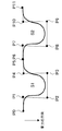
図5は、1本のケーブルの形状を例示した図である。セグメントを複数連ねることによって、図に示すような1本のケーブルの形状を表現することができる。図に示す通過点と通過点の間は、1つのセグメントによって表現される。図では、4つのセグメントを用いて1本のケーブルが表現されている。
【0021】
コンピュータ10の機能について説明する。図6は、コンピュータの機能ブロック図である。図に示すように、コンピュータ10は、入力部11、ベジェ曲線特定部12、スイープ部13、及び表示部14を有している。
【0022】
入力部11は、物品の形状を表示するために必要な入力データを受け付ける。入力データは、図2で示したキーボード10i、マウス10jより入力される。入力データは、具体的には、1.シミュレーションされるワイヤハーネスやケーブルなどの物品の、通過点の位置(留め金で固定する位置、XYZ座標値で示される)とその通過点数、2.通過点の位置での(単位)接線ベクトル、3.物品の全長、4.重力の方向、5.物品の断面半径、6.力が加わらない部分(物品の垂れ下がった部分、撓んだ部分)の撓み半径(撓んだ部分の曲率半径)、7.力が加わる部分(物品を固定した位置の近傍)の限界半径である(物品を固定した位置の近傍の曲率半径)。
【0023】
なお、上記1の通過点の位置は、ワイヤハーネスやケーブルの中心線の通過位置である。また、上記6,7の自由半径、限界半径は、ワイヤハーネスやケーブルの剛性を示す。撓み半径、限界半径は、その値が大きい程、剛性が大きいことを示し、ワイヤハーネスやケーブルの形状のとりうる範囲(例えば、曲がる範囲、撓む範囲)を決めるものである。また、上記2の接線ベクトルは、ワイヤハーネスやケーブルを特定の方向に向けて留める場合に入力され、必須の入力項目ではない。接線ベクトルが入力されない場合は、通過点から一般的にCADシステムで自由曲線形状を作成する場合に使用されるHermite補間法を用いて3次曲線を生成し、生成した3次式の通過点での接線ベクトルを用いる。Hermite補間法以外にもLagrange補間法をはじめとする種々の補間法を用いてもよい。3次式を使用することについては、物体が特に拘束されない場合、その物体の形状は、それ自身の形状エネルギーが小さくなる方向に向かうことを考えると十分であると考えられる。
【0024】
ベジェ曲線特定部12は、入力部11に入力された入力データに基づいて5次ベジェ曲線を特定する。上記1〜7の入力データの全てが入力された場合、1セグメント(通過点間)ごとにおけるベジェ曲線の制御点が特定される。ベジェ曲線特定部12は、各セグメント(セグメント数=通過点数−1)のベジェ曲線を連ねることにより、1本の紐状及び帯状の物品の形状を特定する。
【0025】
図7は、制御点と入力データの関係を説明する図である。図に示す制御点P0,P5の位置は、入力データの通過点の位置によって特定される。制御点P1,P4の位置は、制御点P0,P5における接線ベクトルV0,V1上に配置され、入力データの接線ベクトルとその他の入力データによって特定される。制御点P2,P3の位置も入力データによって特定される。なお、本発明の実施の形態では、制御点P2,P3は、地面に対して水平な位置に設定する。
【0026】
ここで、セグメント間における物品の線長をl、形状半径をr(物品の形状を柱状とする)、撓み半径をRf、限界半径をRsとする。また、図7に示す制御点P1の制御点P0からの距離、制御点P4の制御点P5からの距離を剛性長さLwとする(接線ベクトルV0,V1上の制御点P1,P4の位置は、制御点P0,P5からの距離が、剛性長さLwで等しくなるよう特定される)。なお、線長lは、各セグメントの、両端の通過点間の距離を算出し、物品の全長を比例配分することにより算出される。直接、通過点間の物品長の値を入力データとしてもよい。
【0027】
線長lは、一定であるので、制御点P2,P3の位置を可変することによって、接線ベクトルV0,V1上の制御点P1,P4の位置(剛性長さLw)が求まる。このとき、ベジェ曲線が、撓み半径Rf、限界半径Rsを満たすように特定しなければならない。剛性長さLwは、次の式(1)によって求める。
【0028】
【数1】

Lwm=5Lwmaxの係数5は、扱う物品が軽いものほど大きな値に、重い物ほど小さな値にする必要があるが、経験的に5を設定している。また、式(1)の高さhは、通過点(制御点)間の中央点からベジェ曲線の最も撓んだ部分(最下点)までの距離である。剛性長さLwは、式(1)の高さhを可変し、撓み半径Rf、限界半径Rsを満たすよう求められる。
【0030】
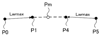
図8は、中央点を説明する図である。図に示すように、中央点Pmは、制御点P0とP5との中央に設定される。中央点Pmは、Pm=(P1+P4)/2によって求められる。
【0031】
図9は、剛性長さと高さの関係を示した図である。図に示すように、縦軸をLw、横軸をh/Lwmとすると、式(1)のLwは図8に示すような関係を有する。高さhが、5Lwmax(h/Lwm=1)のとき、Lwは、(Lwmax+Lwmin)/2となる。すなわち、高さhが、剛性長さLwの最大値Lwmaxの5倍になったとき、剛性長さLwは、(Lwmax+Lwmin)/2となる。この高さh(5Lwmax)を半減期高さと呼び、物品に、無理なく標準的にストレスがかかっている状態とする。
【0032】
Lwmin=1.5Rs、Lwmax=1.5Rfの係数1.5について説明する。図10は、剛性長さの最大値、最小値の係数を説明する図である。図に示すように、曲線Kは、2次式で表される曲線で、撓みを表現する最低レベル曲線式である。曲線Kは、x−y座標に示され、頂点はx=0,y=0である。2次式の曲線Kを表現する標準的なベジェポリゴンを直角二等辺三角形とした場合、その直角二等辺三角形の一辺の長さmは、x=0,y=0での曲率半径Rの2の平方根倍となることから、概ねの値1.5を係数とした。
【0033】
降伏高さについて説明する。物品は、通過点において、例えば、下方から斜め上方に向かって固定されることもある。この場合、物品は、重力によって、下方から上方へ、そして上方から下方に向かって曲がる部分が生じる。重力によって、物品がこれ以上上方に向かわず、重力方向(下方)に降伏する高さを降伏高さとする。最大の降伏高さをとる剛性長さLwyをLwy=N・Lwmaxとする。Nは、例えば、2に設定される。
【0034】
重力作用について説明する。重力作用は以下の3つの条件変更を行う。11.仮想重力方向:真の重力方向と物品の通過点の接線ベクトルとの合成ベクトル方向に向くとする。12.降伏重力方向:11で示した方向に伸びて降伏した後の重力方向。上方に伸びて降伏した場合は、水平となる。13.最終重力方向:真の重力方向。これらの3つの重力方向座標系は保存しておく。
【0035】
ベジェ曲線特定部12は、以上のデータをセットした後、式(1)の高さhを可変し剛性長さLwを算出する。剛性長さLwより、接線ベクトル上の2つの制御点(図7において、制御点P1,P4)の位置が特定される。
【0036】
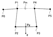
ベジェ曲線特定部12は、中央点Pmから上記11〜13の方向で、高さhの点に中心を持つ最大値Lwmaxを半径とする円を配置する。そして、この円周上に残りの2つの制御点(図7において、制御点P2,P3)を配置する。図11は、円の中心を説明する図である。円の中心Pgは、Pg=Pm+hgで示される。中央点Pmは、制御点P0,P5の中央点であり、高さhgは、中央点Pmから5次ベジェ曲線の最も撓んだ部分(最下点)までの距離である。図に示す方向gは、上記11〜13の方向を示し、高さhgは、上記11〜13の各々場合における値をとりうるので、中心Pgは、3つの値をとりうる。中心Pg、最大値Lwmaxを半径とする円に制御点P2,P3を配置する。
【0037】
ベジェ曲線特定部12は、6つの制御点が同一平面内に存在し、限界曲がり角度の条件を満たしていれば、6つの制御点によって、ベジェ曲線を特定する。限界曲がり角度の条件を満たさなければ、条件を満たすよう新たな制御点の位置を算出する。
【0038】
ここで、限界曲がり角度について説明する。図7における制御点P1−P0と制御点P1−P2がなす角度、及び制御点P3−P4と制御点P5−P4がなす角度を曲がり角度θとする。曲がり角度θは、次の式(2)によって示される。
【0039】
【数2】
曲がり角度θは、物品にストレスがかからない場合、π/2となるように、最大ストレスがかかる場合、θm(1.9π/2)となるように変化する。θm=1.9π/2の係数1.9は、2以上にするとθmがπ以上の値になり、これは曲がり角度θが180度以上にならない(例えば、ワイヤハーネスやケーブルが行って帰るような折れ曲がりにならない)ようにするための係数で、2未満であればよい。式(2)の曲がり角度θが、所定の角度以上にならないよう決められる所定の角度を限界曲がり角度という。
【0041】
図12は、曲がり角度と高さの関係を示した図である。図に示すように、縦軸をθ、横軸をh/Lwmとすると、式(2)のθは図12に示すような関係を有する。高さhが、5Lwmax(h/Lwm=1)のとき、θは、(π/2+θm)/2となる。すなわち、高さhが、剛性長さLwの最大値Lwmaxの5倍になったとき、曲がり角度θは、(π/2+θm)/2となる。この高さh(5Lwmax)を半減期高さと呼び、物品に、無理なく標準的にストレスがかかっている状態とする。
【0042】
ベジェ曲線特定部12は、通過点及び接線ベクトル上以外の制御点(図7における制御点P2,P3)の配置によって、一方の曲がり角度が限界曲がり角度の条件を満たさない場合、その曲がり角度の条件を満たさない制御点と限界曲がり角度の条件を満たす制御点とを結ぶ線と、限界曲がり角度をなす直線との交点を新たな制御点とする。そして、この制御点が上記で説明した円の円周上に位置するよう、その円の中心をスライドさせる。そしてもう一方の制御点の位置を特定する。図13は、限界曲がり角度を満たすようにする制御点を説明する図である。図に示す制御点P1−P0と制御点P1−P2がなす曲がり角度は、限界曲がり角度を満たしていないとする。制御点P3−P4と制御点P5−P4がなす曲がり角度は、限界曲がり角度を満たしているとする。このとき、限界曲がり角をなしている直線l’と制御点P2,P3が結ぶ線の交点を新たな制御点P2aとする。そして、制御点P2aが、上記で説明した制御点P2,P3が配置されるべき円の円周上に位置するように、円の中心をスライドさせる。そして、制御点P2a,P3の位置を特定して、ベジェ曲線を特定する。
【0043】
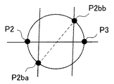
ベジェ曲線特定部12は、通過点及び接線ベクトル上以外の制御点(図7における制御点P2,P3)の配置によって、両方の曲がり角度が限界曲がり角度の条件を満たさない場合、全制御点を含む平面に垂直で、通過点及び接線ベクトル上以外の2つの制御点を含む円の円周上で、その2つの制御点を回し、限界曲がり角度の条件を満たすようにする。図14は、限界曲がり角度を満たすようにする制御点を説明する図である。図に示す制御点P2,P3は、図7の制御点P2,P3を上方から見た状態で示している。図に示す円は、制御点P2,P3とその他の制御点(図7の制御点P0,P1,P4,P5)を含む平面に垂直で、制御点P2,P3を含んでいる。ベジェ曲線特定部12は、円周上で制御点P2,P3を回転し、限界曲がり角度を満たす制御点P2ba,P2bbの位置を特定して、ベジェ曲線を特定する。すなわち、物品のとりうる形状の範囲内でベジェ曲線を特定できない場合、全制御点を含む平面から制御点P2,P3を外し、物品のとりうる形状の範囲内に納まるようにする。
【0044】
ベジェ曲線特定部12は、自己交差を調べる。自己交差とは、ベジェ曲線が一部閉じた曲線をなし、交差することをいう。実際のワイヤハーネスやケーブルにおいて、自己交差ということはありえない。そのため、ベジェ曲線特定部12は、自己交差をする場合、自己交差を避けるよう上記で説明したのと同様に、通過点と接線ベクトル上の制御点以外の制御点を円周上で回転させる。
【0045】
制御点を回転させると、線長lが変わってしまう。そのため、ベジェ曲線特定部12は、再び、ベジェ曲線を生成しなおし、線長を求める。この処理を繰り返し行って、線長が線長lと十分等しくなれば、そのときのベジェ曲線を特定する。線長が線長lと十分等しくならない場合、上記で説明した重力作用を変更する。上記11の重力作用で計算していれば、上記12の重力作用へ、上記12の重力作用で計算していれば、上記13の重力作用で計算し直す。なお、この変更は、非可逆である。重力作用の変更が生じた場合は、高さhを0に、そうでない場合は、h+dhとして増減する。このdhは、2分探索型で+または−に変化する。
【0046】
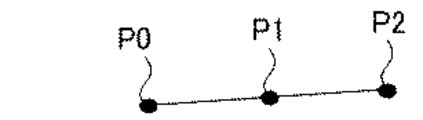
次に、通過点の一方が自由(固定されてない)で、接線ベクトルだけが与えられた場合について説明する。この場合、ベジェ曲線特定部12は、2次(3階)ベジェ曲線を想定する。与えられた長さ(物品の線長)が剛性長さLwの最大値Lwmaxより短い場合は、直線上で長さを調整する。図15は、通過点の一方が自由で線長がLwmaxより小さい場合の制御点を示す図である。図に示す制御点P0は、固定された通過点である。線長が剛性長さLwの最大値Lwmaxより短い場合は、残りの制御点P1,P2は、与えられた接線ベクトル上に配置するようにする。制御点P0〜P2によって、2次ベジェ曲線を特定し、その長さが線長となるように調整する。
【0047】
2次ベジェ曲線を3階表現での限界とし、与えられた線長がそのベジェ曲線の線長より小さい場合は、この2次ベジェ曲線の自由となっている側の制御点を動かして長さ調整する。図16は、通過点の一方が自由で与えられた線長がベジェ曲線の線長より小さい場合の制御点を示す図である。図に示すように、与えられた線長がベジェ曲線の線長Lより小さい場合は、固定されてない側の制御点P2を動かして、長さを調整する。
【0048】
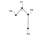
与えられた線長がベジェ曲線の線長Lより長い場合は、3次ベジェ曲線に変更し、決定していない制御点を重力方向に移動して長さを調整する。図17は、通過点の一方が自由で与えられた線長がベジェ曲線の線長より大きい場合の制御点を示す図である。図に示すように、3次ベジェ曲線に変更し、新たな制御点P3を重力方向に移動して長さを調整する。
【0049】
スイープ部13は、ベジェ曲線特定部12によって、ベジェ曲線が特定されると、入力部11に入力された物品の形状半径の円をベジェ曲線に沿ってスイープさせる。これにより、ベジェ曲線は3次元形状となる。なお、物品が帯状であれば、その帯状の断面の縦と横の長さが入力データとなる。その縦と横の長さを有する四角形をベジェ曲線に沿ってスイープさせる。
【0050】
表示部14は、スイープ部13によってスイープされたベジェ曲線を、例えば、図2に示したモニタ10hに表示する。
図6のコンピュータ10の動作について説明する。入力部11は、入力データを受け付ける。ベジェ曲線特定部12は、入力データの物品の全長から、1セグメント間における線長lを算出する。ベジェ曲線特定部12は、線長lを満足するよう式(1)の高さhを変化させ、剛性長さLwを算出する。これにより、接線ベクトル上の制御点が求まる。なお、入力データより、通過点における制御点は求まっている。
【0051】
ベジェ曲線特定部12は、重力作用を考慮し、残りの制御点を算出する。全ての制御点が同一平面内に存在し、限界曲がり角度を満たしていれば、これらの制御点によってベジェ曲線を特定する。
【0052】
残りの制御点が限界曲がり角度を満たしていない場合、ベジェ曲線特定部12は、通過点における制御点と接線ベクトル上の制御点以外の制御点を動かして、限界曲がり角度を満足するようにする。そして、ベジェ曲線特定部12は、この制御点でベジェ曲線を特定する。
【0053】
ベジェ曲線特定部12は、ベジェ曲線の自己交差を調べる。ベジェ曲線特定部12は、ベジェ曲線が自己交差をしていれば、通過点における制御点及び接線ベクトル上の制御点以外の制御点を動かして、自己交差をしないようにする。
【0054】
ベジェ曲線特定部12は、ベジェ曲線を生成しなおし、ベジェ曲線の線長を算出する。ベジェ曲線特定部12は、ベジェ曲線の線長と物品の線長lが十分に等しければ、そのときのベジェ曲線を特定する。ベジェ曲線特定部12は、ベジェ曲線の線長と線長lが十分に等しくない場合は、重力作用を変更してベジェ曲線の線長と物品の線長lが十分に等しくなるようにし、ベジェ曲線を特定する。
【0055】
スイープ部13は、ベジェ曲線特定部12によって特定されたベジェ曲線に沿って、ワイヤハーネス又はケーブルの断面をスイープする。表示部14は、モニタ10hに、スイープしたベジェ曲線を表示する。
【0056】
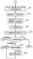
次に、物品の2つの通過点が固定される場合における、ベジェ曲線を特定するまでのコンピュータ10の動作を流れ図を用いて説明する。図18,図19は、物品の2つの通過点が固定される場合のコンピュータの処理の流れを示した流れ図である。コンピュータ10は、以下のステップに従ってベジェ曲線を特定する。
【0057】
[ステップS1]コンピュータ10の入力部は、入力データを受け付ける。入力データは、物品の通過点(留め金)の位置(XYZ座標値)とその数、通過点の位置での接線ベクトル、物品の全長、重力の方向、物品の断面半径、撓み半径、限界半径である。
【0058】
[ステップS2]コンピュータ10のベジェ曲線特定部12は、接線ベクトルが指定されていない(接線ベクトルが入力されなかった場合)通過点を抽出する。ベジェ曲線特定部12は、抽出した通過点の接線ベクトルを、Hermit補間法、Lagrange補間法等によって決定する。
【0059】
[ステップS3]ベジェ曲線特定部12は、通過点間(1セグメント間)の物品の線長lを算出する。ベジェ曲線12は、個々の通過点間の、物品の線長lが指定されていない場合(物品の全長のみが指定されている場合)は、全長を通過点間の距離で比例配分する。
【0060】
[ステップS4]ベジェ曲線特定部12は、仮想重力方向を求める。
[ステップS5]ベジェ曲線特定部12は、通過点間の中央点からベジェ曲線の最も撓んだ部分(最下点)までの距離である高さhを0に設定する。
【0061】
[ステップS6]ベジェ曲線特定部12は、高さhを可変し、剛性長さLw、その最大値Lwmax、限界曲がり角度を算出する。
[ステップS7]ベジェ曲線特定部12は、接線ベクトル上に配置される制御点P1,P4の位置を求める。
【0062】
[ステップS8]ベジェ曲線特定部12は、円の中心Pgを求める。
[ステップS9]ベジェ曲線特定部12は、中心Pg、最大値Lwmaxを半径とする円を決定する。
【0063】
[ステップS10]ベジェ曲線特定部12は、制御点P2,P3を円周上で仮決定する。
[ステップS11]ベジェ曲線特定部12は、現在の制御点P1,P4の位置において、限界曲がり角度を満足しているかを判断する。制御点P1,P4のどちらかが、満足していない場合は、限界曲がり角度の平面と制御点P2,P3を結ぶ交点を新たな制御点P2aとし、制御点P2aが円周上の点となるように円の中心をスライドさせる。制御点P2,P3ともに限界曲がり角度を満足しない場合、制御点P2,P3を円周上で回し、限界曲がり角度を満たす位置に移動する。
【0064】
[ステップS12]ベジェ曲線特定部12は、求まった制御点P0〜P5において、ベジェ曲線を作成する。
[ステップS13]ベジェ曲線特定部12は、自己交差の有無をチェックする。ベジェ曲線特定部12は、自己交差があった場合、物品の半径分を考慮した分だけ円周周りに制御点P2,P3を回転させる。
【0065】
[ステップS14]ベジェ曲線特定部12は、ベジェ曲線を再作成する。ベジェ曲線特定部12は、与えられた物品の線長lと作成したベジェ曲線の長さを比較する。ベジェ曲線の長さが物品の線長lの許容範囲(十分等しい値)内で、全てのセグメントンにおいてベジェ曲線が特定できた場合、処理を終了する。ベジェ曲線の長さが物品の線長lの許容範囲内で、全セグメントンにおいてベジェ曲線が特定できてない場合、次のセグメントについて同処理を行うためステップS4へ進む。許容範囲外であれば、ステップS15へ進む。
【0066】
[ステップS15]ベジェ曲線特定部12は、重力場の降伏条件を検査する。重力場の変更がない場合、高さhを増減させて(2分探索)ステップS6から再計算を行う。ここで、ベジェ曲線の線長が長すぎた場合は、高さhを減少、短すぎた場合は、高さhを増加する。重力場の変更がある場合、ステップS16へ進む。
【0067】
[ステップS16]ベジェ曲線特定部12は、重力作用を変更する。高さhを0にして、ステップS6から再計算を行う。
このようにして、コンピュータ10は、ベジェ曲線を特定する。
【0068】
次に、物品の通過点の一方が自由な場合における、ベジェ曲線を特定するまでのコンピュータ10の動作について説明する。図20は、物品の通過点の一方が自由な場合のコンピュータの処理の流れを示した流れ図である。コンピュータ10は、以下のステップに従ってベジェ曲線を特定する。
【0069】
[ステップS21]コンピュータ10の入力部は、入力データを受け付ける。入力データは、物品の通過点の位置とその数、通過点での接線ベクトル、物品の全長、重力の方向、物品の断面半径、撓み半径、限界半径である。
【0070】
[ステップS22]ベジェ曲線特定部12は、ベジェ曲線の最も撓む部分(最下点)までの距離である高さhを0に設定する。
[ステップS23]ベジェ曲線特定部12は、高さhを可変し、剛性長さLw、その最大値Lwmax、限界曲がり角度を算出する。
【0071】
[ステップS24]ベジェ曲線特定部12は、物品の線長(全長)Lが最大値Lwmax以下か否かを判断する。ベジェ曲線特定部12は、物品の線長Lが最大値Lwmax以下であれば、ステップS25へ進む。物品の線長Lが最大値Lwmaxより大きければ、ステップS26へ進む。
【0072】
[ステップS25]ベジェ曲線特定部12は、ベジェ曲線を直線として作成し、処理を終了する。
[ステップS26]ベジェ曲線特定部12は、2次のベジェ曲線を想定し、制御点P0〜P2を求める。制御点P0は、通過点である。制御点P1は、通過点を通る入力データとして受け付けた接線ベクトル上で、最大値Lxmaxの位置とする。制御点P2は、制御点P0,P1、重力方向を含む平面上で制御点P1の角度が90度で重力方向に最大値Lwmaxの位置とする。ベジェ曲線特定部12は、この制御点P0〜P2で2次のベジェ曲線を作成する。
【0073】
[ステップS27]ベジェ曲線特定部12は、物品の線長Lとベジェ曲線の曲線長Lkを比較する。線長Lと曲線長Lkが等しければ、処理を終了する。物品の線長Lが曲線長Lkより小さければ、制御点P2の位置を制御点P1に近づけ、ステップS24へ進み再計算を行う。物品の線長Lがベジェ曲線長Lkより大きければ、ステップS28へ進む。
【0074】
[ステップS28]ベジェ曲線特定部12は、2次のベジェ曲線では物品を表現できないので、ベジェ曲線の次数を3次に上げる。ベジェ曲線特定部12は、ステップS26で求めた制御点P0〜P2に、制御点P3を追加する。制御点P3は、制御点P2から重力方向にx移動させた点とする。ベジェ曲線特定部12は、制御点P0〜P3でベジェ曲線を再作成する。
【0075】
[ステップS29]ベジェ曲線特定部12は、線長LとステップS28で作成したベジェ曲線の曲線長Lkを比較する。線長Lと曲線長Lkが等しければ、処理を終了する。曲線長Lkが物品の線長Lより大きければ、制御点P3を移動させるxの値を小さくしてステップS28へ進む。曲線長Lkが物品の線長Lより小さければ、制御点P3を移動させるxの値を大きくしてステップS28へ進む。
【0076】
このようにして、コンピュータ10は、ベジェ曲線を特定する。
以上より、柔軟性のある紐状及び帯状の物品の通過点と、その2つの通過点ごとにおける接線ベクトル上の2つの制御点、さらにもう2つの制御点によって5次ベジェ曲線を特定する。そして、5次ベジェ曲線に沿って物品の断面形状をスイープさせ、物品の3次元形状をモニタに表示するようにした。これにより、物品の撓みや捩れを簡易的に表現でき、容易に物品のシミュレーションをすることができる。また、通過点である2つの制御点以外の、4つの制御点の位置を特定すればよく、高速な処理が可能となる。
【0077】
また、接線ベクトル上の2つの制御点を物品の線長及び物品のとりうる形状を満たすように特定することにより、また、もう2つの制御点の位置を、物品の線長及び物品のとりうる形状を満たすように特定することにより、物品の撓みや捩れを簡易的に表現でき、容易に物品のシミュレーションをすることができる。
【0078】
なお、本発明の実施の形態では、ベジェ曲線について説明したが、NURBS(Non−Uniform Rational B−spline)曲線等、その他の自由曲線についても利用可能である。
【0079】
上記の処理機能を実現するプログラムは、コンピュータで読み取り可能な記録媒体に記録しておくことができる。コンピュータで読み取り可能な記録媒体としては、磁気記録装置、光ディスク、光磁気記録媒体、半導体メモリなどがある。磁気記録装置には、ハードディスク装置(HDD)フレキシブルディスク(FD)、磁気テープなどがある。光ディスクには、DVD(Digital Versatile Disc)、DVD−RAM(Random Access Memory)、CD−ROM(Compact Disc Read Only Memory)、CD−R(Recordable)/RW(ReWritable)などがある。光磁気記録媒体には、MO(Magneto−Optical disc)などがある。
【0080】
プログラムを流通させる場合には、例えば、そのプログラムが記録されたDVD、CD−ROMなどの可搬型記録媒体が販売される。また、プログラムをサーバコンピュータの記憶装置に格納しておき、ネットワークを介して、サーバコンピュータから他のコンピュータにそのプログラムを転送することもできる。
【0081】
プログラムを実行するコンピュータは、例えば、可搬型記録媒体に記録されたプログラムもしくはサーバコンピュータから転送されたプログラムを、自己の記憶装置に格納する。そして、コンピュータは、自己の記憶装置からプログラムを読み取り、プログラムに従った処理を実行する。なお、コンピュータは、可搬型記録媒体から直接プログラムを読み取り、そのプログラムに従った処理を実行することもできる。また、コンピュータは、サーバコンピュータからプログラムが転送される毎に、逐次、受け取ったプログラムに従った処理を実行することもできる。
【0082】
(付記1) 柔軟性のある紐状及び帯状の物品をシミュレーションするCADプログラムにおいて、
コンピュータに、
シミュレーションしようとする物品の通過する第1の通過点と第2の通過点と、前記第1の通過点と前記第2の通過点とにおける接線上に配置される第1の制御点と第2の制御点と、及び複数の制御点とによって自由曲線を特定し、
前記自由曲線に沿って前記物品の断面形状をスイープして、前記物品の3次元形状を表示装置に表示する、処理を実行させることを特徴とするCADプログラム。
【0083】
(付記2) 前記第1の制御点と前記第2の制御点との位置を、前記物品の線長及び前記物品のとりうる形状を満たすように特定することを特徴とする付記1記載のCADプログラム。
【0084】
(付記3) 前記複数の制御点の位置を、前記物品の線長及び前記物品のとりうる形状を満たすように特定することを特徴とする付記1記載のCADプログラム。
【0085】
(付記4) 前記物品のとりうる形状の範囲内で前記自由曲線の形状を特定することができない場合、前記第1の通過点、前記第2の通過点、前記第1の制御点、及び前記第2の制御点の存在する平面上にある前記複数の制御点を、前記平面上から外すことを特徴とする付記1記載のCADプログラム。
【0086】
(付記5) 前記自由曲線が交差する場合、前記交差を生じないように前記第1の通過点、前記第2の通過点、前記第1の制御点、及び前記第2の制御点の存在する平面上にある前記複数の制御点を、前記平面上から外すことを特徴とする付記1記載のCADプログラム。
【0087】
(付記6) 前記第1の通過点と前記第2の通過点は、固定された点であることを特徴とする付記1記載のCADプログラム。
(付記7) 前記第1の通過点と前記第2の通過点の一方は、固定された点であることを特徴とする付記1記載のCADプログラム。
【0088】
(付記8) 前記自由曲線は、5次式であることを特徴とする付記1記載のCADプログラム。
【0089】
【発明の効果】
以上説明したように本発明では、シミュレーションしようとする物品の通過する第1の通過点と第2の通過点と、第1の通過点と第2の通過点とにおける接線上に配置される第1の制御点と第2の制御点と、及び複数の制御点とによって自由曲線を特定する。そして、自由曲線に沿って物品の断面形状をスイープして、物品の3次元形状を表示装置に表示するようにした。これにより、物品の撓みや捩れを簡易的に表現でき、容易に物品のシミュレーションをすることができる。
【図面の簡単な説明】
【図1】本発明の原理を説明する原理図である。
【図2】コンピュータのハードウェア構成を示すブロック図である。
【図3】ベジェポリゴンとその曲線の形状を示す。
【図4】複数のセグメントを連ねたときの曲線の形状を示す。
【図5】1本のケーブルの形状を例示した図である。
【図6】コンピュータの機能ブロック図である。
【図7】制御点と入力データの関係を説明する図である。
【図8】中央点を説明する図である。
【図9】剛性長さと高さの関係を示した図である。
【図10】剛性長さの最大値、最小値の係数を説明する図である。
【図11】円の中心を説明する図である。
【図12】曲がり角度と高さの関係を示した図である。
【図13】限界曲がり角度を満たすようにする制御点を説明する図である。
【図14】限界曲がり角度を満たすようにする制御点を説明する図である。
【図15】通過点の一方が自由で線長がLwmaxより小さい場合の制御点を示す図である。
【図16】通過点の一方が自由で与えられた線長がベジェ曲線の線長より小さい場合の制御点を示す図である。
【図17】通過点の一方が自由で与えられた線長がベジェ曲線の線長より大きい場合の制御点を示す図である。
【図18】物品の2つの通過点が固定される場合のコンピュータの処理の流れを示した流れ図である。
【図19】物品の2つの通過点が固定される場合のコンピュータの処理の流れを示した流れ図である。
【図20】物品の1つの通過点が固定される場合のコンピュータの処理の流れを示した流れ図である。
【符号の説明】
1 コンピュータ
2 自由曲線特定手段
3 表示手段
4 表示装置
11 入力部
12 ベジェ曲線特定部
13 スイープ部
14 表示部
A 自由曲線
B1,B2 通過点
C1,C2,D1,D2,P1〜P11 制御点
V0,V1 接線ベクトル[0001]
TECHNICAL FIELD OF THE INVENTION
The present invention relates to a CAD (Computer Aided Design) program, and more particularly to a CAD program that models a flexible three-dimensional shape such as a harness or a cable on a computer and simulates the shape and arrangement.
[0002]
[Prior art]
In recent years, the manufacturing industry has been introducing three-dimensional CAD (for example, see Patent Document 1) with the aim of shortening the development period and reducing development costs. In addition, there is a growing need for verifying that a prototype has been created and verified by regarding a 3D model of a product designed by 3D CAD as a virtual prototype.
[0003]
In three-dimensional CAD, a harness, a cable, and the like are expressed by sweeping a cross-sectional shape along a curve representing a path, but are expressed as a hard rigid body.
In addition, when trying to express flexibility such as bending and twisting caused by hooking a harness or cable on a hook, a large number of parameters are required, computer processing is time consuming, and the cost is high, which is a real problem in product development. Not a target. For this reason, products such as printers, personal computers, and machine tools contain many flexible components such as harnesses and cables, but these cannot be simulated close to the actual behavior of these products. Prototypes were made and verified.
[0004]
[Patent Document 1]
JP-A-5-35826 (page 5, FIG. 1)
[0005]
[Problems to be solved by the invention]
However, in the verification using the prototype, if a defect such as interference with each other or no space for arrangement is found, rework such as returning to the design again and recreating the prototype is required. Therefore, there has been a demand for a CAD program capable of easily expressing bending and torsion and easily performing simulation.
[0006]
The present invention has been made in view of such a point, and it is an object of the present invention to provide a CAD program that can easily express bending and torsion of an article and can easily simulate the article.
[0007]
[Means for Solving the Problems]
In the present invention, in order to solve the above-mentioned problems, in a CAD program for simulating a flexible cord-like or band-like article as shown in FIG. A first control point C1 and a second control point C2 disposed on a tangent line between the point B1 and the second pass point B2, the first pass point B1 and the second pass point B2, and a plurality of A process of specifying a free curve A by the control points D1 and D2, sweeping a cross-sectional shape of the article along the free curve A, and displaying a three-dimensional shape of the article on the
[0008]
According to such a CAD program, the first pass point B1 and the second pass point B2, the first control point C1 and the second control point C2, and the plurality of control points D1 and D2 are used. The free curve A is specified, the sectional shape of the article is swept along the free curve A, and the three-dimensional shape of the article is displayed on the
[0009]
BEST MODE FOR CARRYING OUT THE INVENTION
Hereinafter, embodiments of the present invention will be described with reference to the drawings. FIG. 1 is a principle diagram for explaining the principle of the present invention. As shown in the figure, the
[0010]
The free curve specifying means 2 specifies the free curve A by the passing points B1 and B2 through which the article passes, the control points C1 and C2 arranged on the tangents at the passing points B1 and B2, and the two control points D1 and D2. . In FIG. 1, if the free curve A is a Bezier curve, the Bezier curve is a quintic equation because it is specified by six points. By increasing the control points D1 and D2, the order of the Bezier curve increases.
[0011]
The display means 3 sweeps the cross-sectional shape of the article along the free curve A specified by the free
Here, the shape of the free curve A can be deformed by the arrangement of the control points C1 and C2 and the control points D1 and D2 on the tangent line, and can bend or twist. That is, by changing the control points C1 and C2 and the control points D1 and D2 in consideration of gravity and own weight, for example, it is possible to easily simulate a state when an article is incorporated in the apparatus.
[0012]
As described above, the two passing points B1 and B2 through which the flexible cord-like and band-shaped articles pass, the control points C1 and C2 arranged on the tangents of the passing points B1 and B2, and the two control points D1 and D1 The free curve A is specified by D2. Then, the sectional shape of the article is swept along the free curve A, and the three-dimensional shape of the article is displayed on the
[0013]
Next, a configuration example of an embodiment of the present invention will be described. In the embodiment of the present invention, a case of a free curve, particularly a Bezier curve will be described. FIG. 2 is a block diagram illustrating a hardware configuration of a computer. As shown in the figure, the computer 10 is entirely controlled by a CPU (Central Processing Unit) 10a. To the
[0014]
The
[0015]
A
[0016]
The communication interface 10f is connected to the
[0017]
The present embodiment can be realized by the above hardware configuration.
Here, the shape representation of the article to be simulated will be described. FIG. 3 shows the shape of a Bezier polygon and its curve. The curve shown in the figure is a fifth-order (sixth-order) Bezier curve specified by the control points P0 to P5. This Bezier curve shows the shape of the center line of a flexible cord-like or band-like article such as a wire harness or a cable. Gravity acts downward in the figure, and the Bezier curve (article) is bent downward in the figure.
[0018]
In this figure, control points P0 and P5 are passing points (positions fixed by clasps or the like) of an article to be simulated. Therefore, in order to simulate the shape of the article, the positions (coordinate values) of the remaining four control points P1 to P4 may be determined. The state in FIG. 3 is called one segment. By connecting a plurality of segments, a single wire harness or cable to be simulated is expressed.
[0019]
FIG. 4 shows a curve shape when a plurality of segments are connected. The figure shows a segment S1 in which the shape of the article is specified by the control points P0 to P5, and a segment S2 in which the shape of the article is specified by the control points P6 to P11. The control point P5 of the segment S1 and the control point P6 of the segment S2 overlap. That is, by connecting the control points at the ends of the segments, a complicated shape of the article can be expressed. Then, by sweeping the cross section of the article along the Bezier curve of the connected segments, the three-dimensional shape of the article can be represented.
[0020]
FIG. 5 is a diagram illustrating the shape of one cable. By connecting a plurality of segments, the shape of one cable as shown in the figure can be expressed. The space between the passing points shown in the figure is represented by one segment. In the figure, one cable is represented using four segments.
[0021]
The function of the computer 10 will be described. FIG. 6 is a functional block diagram of a computer. As shown in the figure, the computer 10 has an
[0022]
The
[0023]
In addition, the position of the
[0024]
The Bezier
[0025]
FIG. 7 is a diagram illustrating the relationship between control points and input data. The positions of the control points P0 and P5 shown in the figure are specified by the positions of the passing points of the input data. The positions of the control points P1 and P4 are arranged on the tangent vectors V0 and V1 at the control points P0 and P5, and are specified by the tangent vectors of the input data and other input data. The positions of the control points P2 and P3 are also specified by the input data. In the embodiment of the present invention, the control points P2 and P3 are set at positions that are horizontal to the ground.
[0026]
Here, the line length of the article between the segments is l, the shape radius is r (the shape of the article is columnar), the bending radius is Rf, and the limit radius is Rs. The distance between the control point P1 and the control point P0 shown in FIG. 7 and the distance between the control point P4 and the control point P5 are defined as the rigidity length Lw (the positions of the control points P1 and P4 on the tangent vectors V0 and V1 are , And the distances from the control points P0 and P5 are specified to be equal by the rigid length Lw). The
[0027]
Since the line length l is constant, the positions (rigid length Lw) of the control points P1 and P4 on the tangent vectors V0 and V1 are obtained by changing the positions of the control points P2 and P3. At this time, the Bezier curve must be specified so as to satisfy the deflection radius Rf and the limit radius Rs. The rigid length Lw is obtained by the following equation (1).
[0028]
(Equation 1)
The coefficient 5 of Lwm = 5Lwmax needs to be set to a larger value for a lighter article and a smaller value for a heavier article. The height h in equation (1) is the distance from the center point between the passing points (control points) to the most bent portion (lowest point) of the Bezier curve. The rigid length Lw is obtained by varying the height h of the equation (1) and satisfying the bending radius Rf and the limit radius Rs.
[0030]
FIG. 8 is a diagram illustrating the center point. As shown in the figure, the center point Pm is set at the center between the control points P0 and P5. The center point Pm is determined by Pm = (P1 + P4) / 2.
[0031]
FIG. 9 is a diagram showing a relationship between rigid length and height. As shown in the figure, when the ordinate is Lw and the abscissa is h / Lwm, Lw in equation (1) has a relationship as shown in FIG. When the height h is 5Lwmax (h / Lwm = 1), Lw is (Lwmax + Lwmin) / 2. That is, when the height h becomes five times the maximum value Lwmax of the rigid length Lw, the rigid length Lw becomes (Lwmax + Lwmin) / 2. The height h (5 Lwmax) is called a half-life height, and the article is in a state where stress is applied to the article without difficulty and standard.
[0032]
The coefficient 1.5 of Lwmin = 1.5Rs and Lwmax = 1.5Rf will be described. FIG. 10 is a diagram illustrating the coefficients of the maximum value and the minimum value of the rigidity length. As shown in the figure, a curve K is a curve expressed by a quadratic equation, and is a lowest level curve equation expressing deflection. Curve K is shown in xy coordinates, with vertices x = 0, y = 0. When a standard Bezier polygon expressing the quadratic curve K is a right-angled isosceles triangle, the length m of one side of the right-angled isosceles triangle is 2 of the radius of curvature R at x = 0, y = 0. Therefore, the approximate value of 1.5 was used as the coefficient.
[0033]
The yield height will be described. The article may be fixed at the passing point, for example, obliquely upward from below. In this case, a part of the article is bent by gravity from below to above and from above to below. The height at which the article does not move further upward due to gravity but yields in the direction of gravity (downward) is defined as the yield height. The rigid length Lwy at which the maximum yield height is obtained is defined as Lwy = N · Lwmax. N is set to 2, for example.
[0034]
The gravitational action will be described. The gravitational action changes the following three conditions. 11. Virtual gravity direction: It is assumed that the virtual gravity direction is directed to a combined vector direction of a true gravity direction and a tangent vector of a passing point of an article. 12. Yield gravity direction: The gravity direction after yielding by extending in the direction indicated by 11. If it extends upward and yields, it will be horizontal. 13. Final gravity direction: true gravity direction. These three gravity direction coordinate systems are stored.
[0035]
After setting the above data, the Bezier
[0036]
The Bezier
[0037]
The Bezier
[0038]
Here, the limit bending angle will be described. The angle formed by the control points P1-P0 and P1-P2 and the angle formed by the control points P3-P4 and P5-P4 in FIG. The bending angle θ is represented by the following equation (2).
[0039]
(Equation 2)
The bending angle θ changes to π / 2 when no stress is applied to the article, and changes to θm (1.9π / 2) when the maximum stress is applied. When the coefficient 1.9 of θm = 1.9π / 2 is set to 2 or more, θm becomes a value of π or more, which means that the bend angle θ does not become 180 ° or more (for example, when a wire harness or a cable returns. This is a coefficient for preventing a sharp bend) and may be less than 2. A predetermined angle determined so that the bending angle θ in Expression (2) does not exceed a predetermined angle is referred to as a limit bending angle.
[0041]
FIG. 12 is a diagram illustrating a relationship between a bending angle and a height. As shown in the drawing, when the vertical axis is θ and the horizontal axis is h / Lwm, θ in Expression (2) has a relationship as shown in FIG. When the height h is 5 Lwmax (h / Lwm = 1), θ is (π / 2 + θm) / 2. That is, when the height h is five times the maximum value Lwmax of the rigid length Lw, the bending angle θ is (π / 2 + θm) / 2. The height h (5 Lwmax) is called a half-life height, and the article is in a state where stress is applied to the article without difficulty and standard.
[0042]
The Bezier
[0043]
The Bezier
[0044]
The Bezier
[0045]
When the control point is rotated, the line length l changes. Therefore, the Bezier
[0046]
Next, a case where one of the passing points is free (not fixed) and only a tangent vector is given will be described. In this case, the Bezier
[0047]
Let the quadratic Bezier curve be the limit in the third-order expression, and if the given line length is smaller than the line length of the Bezier curve, move the control point on the free side of this quadratic Bezier curve to the length. adjust. FIG. 16 is a diagram showing control points when one of the passing points is freely given and the line length is smaller than the line length of the Bezier curve. As shown in the figure, when the given line length is smaller than the line length L of the Bezier curve, the length is adjusted by moving the control point P2 on the non-fixed side.
[0048]
If the given line length is longer than the line length L of the Bezier curve, the line is changed to a cubic Bezier curve, and the undetermined control points are moved in the direction of gravity to adjust the length. FIG. 17 is a diagram illustrating the control points when one of the passing points is freely given and the line length is larger than the line length of the Bezier curve. As shown in the figure, the curve is changed to a cubic Bezier curve, and a new control point P3 is moved in the direction of gravity to adjust the length.
[0049]
When the Bezier
[0050]
The
The operation of the computer 10 in FIG. 6 will be described. The
[0051]
The Bezier
[0052]
If the remaining control points do not satisfy the limit bend angle, the Bezier
[0053]
The Bezier
[0054]
The Bezier
[0055]
The
[0056]
Next, the operation of the computer 10 until the Bezier curve is specified when the two passing points of the article are fixed will be described using a flowchart. FIG. 18 and FIG. 19 are flowcharts showing the processing flow of the computer when the two passing points of the article are fixed. The computer 10 specifies a Bezier curve according to the following steps.
[0057]
[Step S1] The input unit of the computer 10 receives input data. The input data includes the position (XYZ coordinate value) and the number of passing points (clasps) of the article, the tangent vector at the position of the passing point, the total length of the article, the direction of gravity, the sectional radius of the article, the bending radius, and the limiting radius. It is.
[0058]
[Step S2] The Bezier
[0059]
[Step S3] The Bezier
[0060]
[Step S4] The Bezier
[Step S5] The Bezier
[0061]
[Step S6] The Bezier
[Step S7] The Bezier
[0062]
[Step S8] The Bezier
[Step S9] The Bezier
[0063]
[Step S10] The Bezier
[Step S11] The Bezier
[0064]
[Step S12] The Bezier
[Step S13] The Bezier
[0065]
[Step S14] The Bezier
[0066]
[Step S15] The Bezier
[0067]
[Step S16] The Bezier
In this way, the computer 10 specifies a Bezier curve.
[0068]
Next, the operation of the computer 10 until the Bezier curve is specified when one of the passing points of the article is free will be described. FIG. 20 is a flowchart showing the flow of processing of the computer when one of the passing points of the article is free. The computer 10 specifies a Bezier curve according to the following steps.
[0069]
[Step S21] The input unit of the computer 10 receives input data. The input data includes the position and number of passing points of the article, the tangent vector at the passing point, the total length of the article, the direction of gravity, the section radius of the article, the bending radius, and the limit radius.
[0070]
[Step S22] The Bezier
[Step S23] The Bezier
[0071]
[Step S24] The Bezier
[0072]
[Step S25] The Bezier
[Step S26] The Bezier
[0073]
[Step S27] The Bezier
[0074]
[Step S28] The Bezier
[0075]
[Step S29] The Bezier
[0076]
In this way, the computer 10 specifies a Bezier curve.
As described above, the fifth-order Bezier curve is specified by the passing points of the flexible string-shaped and band-shaped articles, two control points on the tangent vector at each of the two passing points, and two more control points. Then, the sectional shape of the article was swept along the fifth-order Bezier curve, and the three-dimensional shape of the article was displayed on the monitor. This makes it possible to simply express the flexure and twist of the article, and easily simulate the article. Further, it is only necessary to specify the positions of four control points other than the two control points that are passing points, and high-speed processing can be performed.
[0077]
Also, by specifying two control points on the tangent vector so as to satisfy the line length of the article and the possible shape of the article, the positions of the other two control points can be determined by the line length of the article and the possible article. By specifying the shape so as to satisfy the shape, it is possible to simply express the bending or twisting of the article, and it is possible to easily simulate the article.
[0078]
In the embodiment of the present invention, a Bezier curve has been described, but other free curves such as a NURBS (Non-Uniform Rational B-spline) curve can also be used.
[0079]
A program for realizing the above processing functions can be recorded on a computer-readable recording medium. Computer-readable recording media include magnetic recording devices, optical disks, magneto-optical recording media, and semiconductor memories. The magnetic recording device includes a hard disk device (HDD), a flexible disk (FD), and a magnetic tape. Examples of the optical disc include a DVD (Digital Versatile Disc), a DVD-RAM (Random Access Memory), a CD-ROM (Compact Disc Read Only Memory), and a CD-R (Recordable) / RW (ReWritable). Magneto-optical recording media include MO (Magneto-Optical disc).
[0080]
When distributing the program, portable recording media such as DVDs and CD-ROMs on which the program is recorded are sold. Alternatively, the program may be stored in a storage device of a server computer, and the program may be transferred from the server computer to another computer via a network.
[0081]
The computer that executes the program stores, for example, the program recorded on the portable recording medium or the program transferred from the server computer in its own storage device. Then, the computer reads the program from its own storage device and executes processing according to the program. The computer can also read the program directly from the portable recording medium and execute processing according to the program. Further, the computer may execute the processing according to the received program each time the program is transferred from the server computer.
[0082]
(Supplementary Note 1) In a CAD program that simulates flexible string-like and band-like articles,
On the computer,
A first pass point and a second pass point through which the article to be simulated passes, and a first control point and a second control point arranged on a tangent line between the first pass point and the second pass point. And a free curve is specified by the control points and a plurality of control points,
A CAD program for executing a process of sweeping a cross-sectional shape of the article along the free curve and displaying a three-dimensional shape of the article on a display device.
[0083]
(Supplementary Note 2) The CAD according to
[0084]
(Supplementary Note 3) The CAD program according to
[0085]
(Supplementary Note 4) When the shape of the free curve cannot be specified within the range of the shape that the article can take, the first pass point, the second pass point, the first control point, and the The CAD program according to
[0086]
(Supplementary Note 5) When the free curves intersect, the first pass point, the second pass point, the first control point, and the second control point exist so as not to cause the intersection. The CAD program according to
[0087]
(Supplementary note 6) The CAD program according to
(Supplementary note 7) The CAD program according to
[0088]
(Supplementary Note 8) The CAD program according to
[0089]
【The invention's effect】
As described above, according to the present invention, the first and second passage points through which the article to be simulated passes, and the first and second passage points disposed on the tangent line between the first and second passage points. A free curve is specified by one control point, a second control point, and a plurality of control points. Then, the sectional shape of the article is swept along the free curve, and the three-dimensional shape of the article is displayed on the display device. This makes it possible to simply express the flexure and twist of the article, and easily simulate the article.
[Brief description of the drawings]
FIG. 1 is a principle diagram illustrating the principle of the present invention.
FIG. 2 is a block diagram illustrating a hardware configuration of a computer.
FIG. 3 shows the shape of a Bezier polygon and its curve.
FIG. 4 shows the shape of a curve when a plurality of segments are connected.
FIG. 5 is a diagram illustrating the shape of one cable.
FIG. 6 is a functional block diagram of a computer.
FIG. 7 is a diagram illustrating the relationship between control points and input data.
FIG. 8 is a diagram illustrating a center point.
FIG. 9 is a diagram showing a relationship between rigid length and height.
FIG. 10 is a diagram illustrating coefficients of a maximum value and a minimum value of the rigidity length.
FIG. 11 is a diagram illustrating the center of a circle.
FIG. 12 is a diagram showing a relationship between a bending angle and a height.
FIG. 13 is a diagram illustrating control points for satisfying a limit bending angle.
FIG. 14 is a diagram illustrating control points for satisfying a limit bending angle.
FIG. 15 is a diagram showing control points when one of the passing points is free and the line length is smaller than Lwmax.
FIG. 16 is a diagram illustrating control points in a case where a line length freely given to one of the passing points is smaller than a line length of a Bezier curve.
FIG. 17 is a diagram illustrating control points when a line length freely given to one of the passing points is larger than the line length of the Bezier curve.
FIG. 18 is a flowchart showing a processing flow of a computer when two passing points of an article are fixed.
FIG. 19 is a flowchart showing a processing flow of a computer when two passing points of an article are fixed.
FIG. 20 is a flowchart showing a processing flow of a computer when one passing point of an article is fixed.
[Explanation of symbols]
1 computer
2 Free curve specifying means
3 Display means
4 Display device
11 Input section
12 Bezier curve specifying part
13 Sweep section
14 Display
A free curve
B1, B2 passing point
C1, C2, D1, D2, P1 to P11 Control points
V0, V1 Tangent vector
Claims (5)
コンピュータに、
シミュレーションしようとする物品の通過する第1の通過点と第2の通過点と、前記第1の通過点と前記第2の通過点とにおける接線上に配置される第1の制御点と第2の制御点と、及び複数の制御点とによって自由曲線を特定し、
前記自由曲線に沿って前記物品の断面形状をスイープして、前記物品の3次元形状を表示装置に表示する、処理を実行させることを特徴とするCADプログラム。In a CAD program that simulates flexible strings and strips,
On the computer,
A first pass point and a second pass point through which the article to be simulated passes, and a first control point and a second control point arranged on a tangent line between the first pass point and the second pass point. And a free curve is specified by the control points and a plurality of control points,
A CAD program for executing a process of sweeping a cross-sectional shape of the article along the free curve and displaying a three-dimensional shape of the article on a display device.
Priority Applications (1)
| Application Number | Priority Date | Filing Date | Title |
|---|---|---|---|
| JP2003158804A JP3974077B2 (en) | 2003-06-04 | 2003-06-04 | CAD program |
Applications Claiming Priority (1)
| Application Number | Priority Date | Filing Date | Title |
|---|---|---|---|
| JP2003158804A JP3974077B2 (en) | 2003-06-04 | 2003-06-04 | CAD program |
Publications (2)
| Publication Number | Publication Date |
|---|---|
| JP2004362191A true JP2004362191A (en) | 2004-12-24 |
| JP3974077B2 JP3974077B2 (en) | 2007-09-12 |
Family
ID=34052038
Family Applications (1)
| Application Number | Title | Priority Date | Filing Date |
|---|---|---|---|
| JP2003158804A Expired - Fee Related JP3974077B2 (en) | 2003-06-04 | 2003-06-04 | CAD program |
Country Status (1)
| Country | Link |
|---|---|
| JP (1) | JP3974077B2 (en) |
Cited By (8)
| Publication number | Priority date | Publication date | Assignee | Title |
|---|---|---|---|---|
| WO2008084517A1 (en) * | 2007-01-10 | 2008-07-17 | Fujitsu Limited | System, method and program for generating route curve |
| JP2008204059A (en) * | 2007-02-19 | 2008-09-04 | Nissan Motor Co Ltd | Work deformation calculation device and work deformation calculation method |
| WO2009001403A1 (en) * | 2007-06-26 | 2008-12-31 | Fujitsu Limited | Design support device, method, and program |
| JP2009193156A (en) * | 2008-02-12 | 2009-08-27 | Panasonic Corp | Cable wiring path design support apparatus and method |
| JP2010277115A (en) * | 2009-05-26 | 2010-12-09 | Fujitsu Ltd | Harness verification device and harness verification program |
| JP4851542B2 (en) * | 2007-01-10 | 2012-01-11 | 富士通株式会社 | Route curve generation system, method, and program |
| US20220331958A1 (en) * | 2021-04-15 | 2022-10-20 | Kabushiki Kaisha Kobe Seiko Sho (Kobe Steel, Ltd.) | Multi-joint-robot linear-member-shape simulator, multi-joint-robot linear-member-shape simulation method, and multi-joint-robot linear-member-shape simulation program |
| JP7630347B2 (en) | 2021-04-27 | 2025-02-17 | 三菱電機株式会社 | DESIGN ASSISTANCE DEVICE, LINEAR MEMBER CLASSIFICATION METHOD, AND PROGRAM |
-
2003
- 2003-06-04 JP JP2003158804A patent/JP3974077B2/en not_active Expired - Fee Related
Cited By (17)
| Publication number | Priority date | Publication date | Assignee | Title |
|---|---|---|---|---|
| US8301424B2 (en) | 2007-01-10 | 2012-10-30 | Fujitsu Limited | Route curve generation system, method and storage medium |
| WO2008084535A1 (en) * | 2007-01-10 | 2008-07-17 | Fujitsu Limited | System, method and program for generating curve of cable |
| WO2008084517A1 (en) * | 2007-01-10 | 2008-07-17 | Fujitsu Limited | System, method and program for generating route curve |
| JP4851542B2 (en) * | 2007-01-10 | 2012-01-11 | 富士通株式会社 | Route curve generation system, method, and program |
| JP2008204059A (en) * | 2007-02-19 | 2008-09-04 | Nissan Motor Co Ltd | Work deformation calculation device and work deformation calculation method |
| WO2009001403A1 (en) * | 2007-06-26 | 2008-12-31 | Fujitsu Limited | Design support device, method, and program |
| JP5062254B2 (en) * | 2007-06-26 | 2012-10-31 | 富士通株式会社 | Design support apparatus, method and program |
| US8041544B2 (en) | 2007-06-26 | 2011-10-18 | Fujitsu Limited | Support device, method, and storage medium used to design a part in string or belt form |
| JP2009193156A (en) * | 2008-02-12 | 2009-08-27 | Panasonic Corp | Cable wiring path design support apparatus and method |
| JP2010277115A (en) * | 2009-05-26 | 2010-12-09 | Fujitsu Ltd | Harness verification device and harness verification program |
| US8370116B2 (en) | 2009-05-26 | 2013-02-05 | Fujitsu Limited | Harness verification apparatus, harness verification method and storage medium |
| US20220331958A1 (en) * | 2021-04-15 | 2022-10-20 | Kabushiki Kaisha Kobe Seiko Sho (Kobe Steel, Ltd.) | Multi-joint-robot linear-member-shape simulator, multi-joint-robot linear-member-shape simulation method, and multi-joint-robot linear-member-shape simulation program |
| CN115213895A (en) * | 2021-04-15 | 2022-10-21 | 株式会社神户制钢所 | Linear member shape simulator for articulated robot, method therefor, and program therefor |
| JP7570966B2 (en) | 2021-04-15 | 2024-10-22 | 株式会社神戸製鋼所 | Linear member shape simulator for articulated robot, method and program |
| US12257717B2 (en) * | 2021-04-15 | 2025-03-25 | Kobe Steel, Ltd. | Multi-joint-robot linear-member-shape simulator, multi-joint-robot linear-member-shape simulation method, and multi-joint-robot linear-member-shape simulation program |
| CN115213895B (en) * | 2021-04-15 | 2025-07-29 | 株式会社神户制钢所 | Linear member shape simulator for multi-joint robot, method and recording medium |
| JP7630347B2 (en) | 2021-04-27 | 2025-02-17 | 三菱電機株式会社 | DESIGN ASSISTANCE DEVICE, LINEAR MEMBER CLASSIFICATION METHOD, AND PROGRAM |
Also Published As
| Publication number | Publication date |
|---|---|
| JP3974077B2 (en) | 2007-09-12 |
Similar Documents
| Publication | Publication Date | Title |
|---|---|---|
| US10996651B2 (en) | Orientation of a real object for 3D printing | |
| US8538737B2 (en) | Curve editing with physical simulation of mass points and spring forces | |
| US7468730B2 (en) | Volumetric hair simulation | |
| US10831172B2 (en) | Designing a part manufacturable by milling operations | |
| US20130124149A1 (en) | System and Method for Creating Editable Feature Curves for a Multi-Dimensional Model | |
| EP3038060B1 (en) | 3D modeled object defined by a grid of control points | |
| US7236170B2 (en) | Wrap deformation using subdivision surfaces | |
| US20070229544A1 (en) | Nurbs surface deformation apparatus and the method using 3d target curve | |
| WO1998044454A9 (en) | Method and system for view-dependent refinement of progressive meshes | |
| EP2045778A2 (en) | Method and apparatus for animating the dynamics of hair and similar objects | |
| KR100861161B1 (en) | Computer-readable recording media recording three-dimensional display programs, three-dimensional display devices, and three-dimensional display methods | |
| US10242498B1 (en) | Physics based garment simulation systems and methods | |
| US8358311B1 (en) | Interpolation between model poses using inverse kinematics | |
| JP3974077B2 (en) | CAD program | |
| JP5764362B2 (en) | Wiring design method, wiring simulation apparatus and program | |
| US8305378B2 (en) | Method and apparatus for approximating hair and similar objects during animation | |
| CN117422818A (en) | Modeling system for three-dimensional virtual model | |
| US20120206456A1 (en) | Methods and Systems for Generating Continuous Surfaces from Polygonal Data | |
| US8239174B2 (en) | Method for disposing a component part while taking into account a positional relationship between the component part and other installed objects existing within a space | |
| US12293468B2 (en) | System and method of generating smooth spline surface model preserving feature of physical object | |
| JP2009086842A (en) | Harness design support apparatus, method and program | |
| US8704828B1 (en) | Inverse kinematic melting for posing models | |
| JP2005078416A (en) | Method, device and program for generating analysis model and its recording medium | |
| Bertka | An introduction to Bézier curves, B-splines, and tensor product surfaces with history and applications | |
| JPH0561961A (en) | System and device for interactive processing of computer animation |
Legal Events
| Date | Code | Title | Description |
|---|---|---|---|
| A621 | Written request for application examination |
Free format text: JAPANESE INTERMEDIATE CODE: A621 Effective date: 20040906 |
|
| A131 | Notification of reasons for refusal |
Free format text: JAPANESE INTERMEDIATE CODE: A131 Effective date: 20061128 |
|
| A521 | Written amendment |
Free format text: JAPANESE INTERMEDIATE CODE: A523 Effective date: 20070125 |
|
| A02 | Decision of refusal |
Free format text: JAPANESE INTERMEDIATE CODE: A02 Effective date: 20070227 |
|
| A521 | Written amendment |
Free format text: JAPANESE INTERMEDIATE CODE: A523 Effective date: 20070420 |
|
| A911 | Transfer to examiner for re-examination before appeal (zenchi) |
Free format text: JAPANESE INTERMEDIATE CODE: A911 Effective date: 20070508 |
|
| TRDD | Decision of grant or rejection written | ||
| A01 | Written decision to grant a patent or to grant a registration (utility model) |
Free format text: JAPANESE INTERMEDIATE CODE: A01 Effective date: 20070612 |
|
| A61 | First payment of annual fees (during grant procedure) |
Free format text: JAPANESE INTERMEDIATE CODE: A61 Effective date: 20070613 |
|
| R150 | Certificate of patent or registration of utility model |
Free format text: JAPANESE INTERMEDIATE CODE: R150 |
|
| FPAY | Renewal fee payment (event date is renewal date of database) |
Free format text: PAYMENT UNTIL: 20100622 Year of fee payment: 3 |
|
| FPAY | Renewal fee payment (event date is renewal date of database) |
Free format text: PAYMENT UNTIL: 20110622 Year of fee payment: 4 |
|
| FPAY | Renewal fee payment (event date is renewal date of database) |
Free format text: PAYMENT UNTIL: 20120622 Year of fee payment: 5 |
|
| FPAY | Renewal fee payment (event date is renewal date of database) |
Free format text: PAYMENT UNTIL: 20120622 Year of fee payment: 5 |
|
| FPAY | Renewal fee payment (event date is renewal date of database) |
Free format text: PAYMENT UNTIL: 20130622 Year of fee payment: 6 |
|
| LAPS | Cancellation because of no payment of annual fees |