JP2004359302A - Tray for microwave oven use, and its food packaging body - Google Patents
Tray for microwave oven use, and its food packaging body Download PDFInfo
- Publication number
- JP2004359302A JP2004359302A JP2003160522A JP2003160522A JP2004359302A JP 2004359302 A JP2004359302 A JP 2004359302A JP 2003160522 A JP2003160522 A JP 2003160522A JP 2003160522 A JP2003160522 A JP 2003160522A JP 2004359302 A JP2004359302 A JP 2004359302A
- Authority
- JP
- Japan
- Prior art keywords
- leg
- tray
- fold
- lock
- cut
- Prior art date
- Legal status (The legal status is an assumption and is not a legal conclusion. Google has not performed a legal analysis and makes no representation as to the accuracy of the status listed.)
- Withdrawn
Links
Images


Abstract
Description
【0001】
【発明の属する技術分野】
本発明は、ピザなどの食品を載置して電子レンジでの加熱調理に用いるトレイ、及び、そのトレイを用いた食品包装体に関する。
【0002】
【従来の技術】
ピザなどの食品を載置して電子レンジでの加熱調理に用いる略平皿状のトレイは公知である。
トレイの底面を電子レンジのテーブル上に直に置いて加熱調理を行うと、加熱ムラが生じて、食品が均一に加熱されにくい。局所的に、過剰に加熱されたり、逆に加熱が不足する部分が発生しやすい。
【0003】
特に、食品の上面部付近は過加熱される傾向があり、例えば、ピザの場合、上面に配置されたチーズやトッピングの吹きこぼれの原因となっている。この吹きこぼれをなくすために、調理時間を短くすると、底部のピザクラストのクリスピー感が喪失してしまう。
【0004】
他方、トレイの底面近くの食品は、加熱が不足する傾向がある。この加熱不足をなくすためには、トレイに脚部を設けて底上げすることが考えられる。
トレイに脚部を設けた従来技術には、
【特許文献1】
特開平8−295372号
【特許文献2】
実公平8−6743号
などがある。
しかし、いずれの従来技術によっても、トレイを簡単に折るだけで脚部を形成することはできなかった。
【0005】
【発明が解決しようとする課題】
そこで、本発明は、トレイの一部を折るだけで安定した脚部を簡単に形成でき、均一な加熱に寄与する電子レンジ用トレイ、及び、それを用いた食品包装体を提供することを課題とする。
【0006】
【課題を解決するための手段】
上記課題を達成するために、本発明の電子レンジ用トレイは、次の構成を備える。
すなわち、食品を載置して電子レンジでの加熱調理に用いる略平皿状のトレイであって、食品が載置されるトレイの底面と、その底面の周縁部から上方に延伸する側面とを備え、側面には、少なくとも略上下方向に設けられた2本の脚部用切れ目と、その両脚部用切れ目の略下端同士を繋ぐ脚部用折れ目とを有し、脚部用切れ目と脚部用折れ目とで囲まれた側面の一部領域で形成される脚部を、脚部用折れ目を介して外側下方へ折り曲げ、底面より下方に至らせることで、底面を脚部で底上げすることを特徴とする。
【0007】
ここで、脚部用折れ目の上下両近傍に、脚部用折れ目と略平行な2本のロック用折れ目を設けると共に、その両ロック用折れ目の略両端同士を、曲折した形状で繋ぐ2本のロック用切れ目とを設け、ロック用切れ目とロック用折れ目とで囲まれた側面の一部領域で形成されるロック部を、ロック用折れ目を介して側方へ折り曲げ、ロック用切れ目に近接するロック部側縁をロック用切れ目に近接する側面に係合させることで、脚部の形態を固定するようにしてもよい。
【0008】
同様に、脚部用折れ目の上部近傍に、脚部用折れ目と略平行であり、その一部に下方へ向かって屈曲した屈曲部を備える突状ロック用切れ目を設けると共に、脚部用折れ目の近傍の底面に、突状ロック用切れ目の屈曲部と略同一の長さの孔状ロック用切れ目とを設け、突状ロック用切れ目の屈曲部で部分的に囲まれた側面の一部領域で形成されるロック部を、突状ロック用切れ目を介して内方へ湾曲させ、孔状ロック用切れ目に係合させることで、脚部の形態を固定するようにしてもよい。
【0009】
また、脚部に、略上下方向のリブを設けて、脚部の補強に寄与させてもよい。
【0010】
脚部が底面より下方に至っている底上げ高さを、約3〜50mmにして、有効な均一加熱に寄与させてもよい。
【0011】
脚部用折れ目の長さをトレイ底面の径の約50%以上にすると共に、脚部の下端に形成される接地線部の長さをトレイ底面の径の約40%以上にして、脚部の強度安定に寄与させてもよい。
【0012】
底面に、脚部用折れ目と略平行なリブを設けて、底面の補強に寄与させてもよい。
【0013】
脚部に、その下端から上方に連なる補助脚用折れ目と、その補助脚用折れ目に連なる少なくとも1本の補助脚用切れ目とを設け、補助脚用折れ目と補助脚用切れ目とで囲まれた脚部の一部領域で形成される補助脚を、補助脚用折れ目を介して折り曲げることで、補助脚を構成して、脚部の補強に寄与させてもよい。
【0014】
このような電子レンジ用トレイに、加熱により最適化される食品を載置し、包装手段で包装することで食品包装体を形成してもよい。
【0015】
【発明の実施の形態】
以下に、本発明の実施形態を、図面に示した実施例を基に説明する。ここでは、シュレッドチーズがトッピングされたピザを収容する径約20cmの平皿状トレイを例示するが、本発明の電子レンジ用トレイは、加熱により最適化される食品を載置する略平皿状のトレイ一般に適用可能である。
【0016】
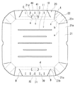
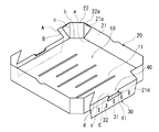
図1は、本発明によるトレイを形成する厚紙の展開図、図2は、その厚紙を組み立てて形成したトレイの斜視図である。
トレイの材質としては、紙の他には、合成樹脂など、硬度のある薄片状に成形可能で折り曲げることができるものが適宜利用できる。
【0017】
トレイの概形は略平皿状であり、食品が載置される略正方形の底面(10)と、その底面の周縁部から上方に延伸する側面(20)とを備える。
図示の例では、底面(10)は、正方形の角に短い辺が形成されることで、8角形になっている。そのため、側面(20)は、それぞれ4つの大側面部(21)及び小側面部(22)を有する。
底面(10)と大側面部(21)及び小側面部(22)との間の皿成形用折れ目(a)(b)と、小側面部(22)に備わる2本の皿成形用折れ目(c)を介して折ると共に、大側面部(21)と小側面部(22)との間の皿成形用切れ目(A)を介して隣接する大側面部(21)の縁(21a)と小側面部(22)の縁(22a)とを接着剤等で接合することによって、側面(20)が底面(10)から上方に延伸した皿状に形成される。
【0018】
対向する2つの大側面部(21)は、略上下方向に設けられた2本の脚部用切れ目(B)(B)と、その両脚部用切れ目(B)(B)の略下端部(21b)(21b)同士を繋ぐ脚部用折れ目(d)とを有する。
脚部用切れ目(B)(B)と脚部用折れ目(d)とで囲まれた側面の一部領域で形成される脚部(30)を、脚部用折れ目(d)を介して外側下方へ折り曲げ、底面(10)より下方に至らせると、図2に示したように、底面(10)を脚部(30)によって底上げすることができる。
なお、脚部用切れ目(B)など任意の切れ目に、繋がっている部分を断続的に設けて、輸送時の破損防止に寄与させてもよい。また、逆に、脚部用折れ目(d)など任意の折れ目に、切れ目を断続的に設けて、折り易さの向上に寄与させてもよい。
【0019】
脚部用切れ目(B)の略下端部(21b)には、円弧状のスリット(21c)が連っている。
これによって、脚部(30)を折り曲げた際に、大側面部(21)が脚部用切れ目(B)に連続して過度に切れ込まれてしまうことが防止される。
【0020】
脚部(30)が底面(10)より下方に至っている底上げ高さは、約10〜15mmが最適であるが、高さ3〜50mmでも直にターンテーブル上にトレイを載置するのに比べ効果が得られる。
このように底面(10)を底上げすると、電子レンジテーブルとの間に空隙が生じるので、電子レンジテーブルに反射されたマイクロ波を底面(10)の下面に誘導でき、均一な加熱調理を行えるようになる。また、底面(10)の熱が電子レンジテーブルに伝わって逃げないため、加熱された食品底部の食感を保持できる。
【0021】
脚部用折れ目(d)の長さが、トレイ底面(10)の径の約50%以上であり、脚部(30)の下端に形成される接地線部(31)の長さが、トレイ底面(10)の径の約40%以上であるのが、強度安定のために好適である。
脚部用折れ目(d)は長めの方が、トレイ全体の剛性の点で好ましい。
【0022】
トレイ全体の剛性増強の点では、底面(10)に、脚部用折れ目(d)と略平行なリブ(11)を設けることも効果的である。
【0023】
同様に、脚部(30)に、略上下方向のリブ(32)を設けて、脚部の剛性を補強してもよい。なお、脚部の補強は、後述の図5に示す補助脚(33)によっても行われる。
【0024】
図3は、脚部(30)周辺を示す斜視図である。
脚部(30)には、その形態を固定する次のようなロック部(40)が備わっている。
脚部用折れ目(d)の上下両近傍に、脚部用折れ目(d)と略平行な2本のロック用折れ目(e)(f)が設けられ、その両ロック用折れ目(e)(f)の略両端同士が、ジグザク状に曲折した形状の2本のロック用切れ目(C)(C)で繋がっている。
このロック用切れ目(C)(C)とロック用折れ目(e)(f)とで囲まれた側面の一部領域で形成されるロック部(40)を、ロック用折れ目(e)(f)を介して側方へ折り曲げると、ロック用切れ目(C)に近接して側方へ突出したロック部側縁(41)を、ロック用切れ目(C)に近接して側方に突出した大側面部舌片(21d)に係合させることができ、脚部(30)を折り曲げた形態が保持される。
【0025】
トレイ用紙の厚みを考慮すると、脚部用折れ目(d)とロック用折れ目(e)との間隔を、脚部用折れ目(d)とロック用折れ目(f)との間隔より若干長くした方が、ロック部(40)の折り曲げ形態の安定に寄与する。
図示の例では、脚部用折れ目(d)とロック用折れ目(e)との間隔を5mm、脚部用折れ目(d)とロック用折れ目(f)との間隔を4mmとしている。
【0026】
図4は、別実施例の脚部(30)周辺を示す斜視図である。
大側面部(21)において、脚部用切れ目(B)が外周まで達していない点が、前記実施例と異なる。
そのため、両脚部用切れ目(B)(B)の端部同士を繋ぐと共に接地線部として用いられる脚部用切れ目(D)が備わっている。
そして、脚部(30)は、脚部用切れ目(B)(B)と脚部用折れ目(d)と、更に、脚部用切れ目(D)とで囲まれた領域で形成される。
このように、脚部(30)を切り抜き式で用意してもよい。
【0027】
底面(10)の上面或いは下面には、マイクロ波によって発熱する発熱体から成る蒸着フィルム(サセプター)を付設してもよい。加熱されにくい位置に蒸着フィルムを設けることで、均一な加熱調理に寄与する。
なお、蒸着フィルムは、マイクロ波によるスパーク防止のために、合成樹脂等の被覆部材で覆うことが好ましい。
【0028】
以上のような電子レンジ用トレイに、シュレッドチーズ等がトッピングされたピザなどの食品を載置し、フィルムやカートンなどの包装手段で包装すると、流通及び加熱調理に便利な食品包装体として提供できる。
すると、電子レンジで調理後、加熱調理された食品を、外観を損なうことなくそのままの熱い状態で食卓に配膳することができる。
【0029】
図5は、別実施例の脚部(30)周辺を示す斜視図である。
脚部(30)の左右端部に、その下端から上方に連なる補助脚用折れ目(g)と、その補助脚用折れ目(g)に連なる補助脚用切れ目(E)とが設けられている。
補助脚用折れ目(g)と補助脚用切れ目(E)とで囲まれたまれた脚部の一部領域で形成される補助脚(33)を、補助脚用折れ目(g)を介して折り曲げると、1次元的に直線上であった接地線部(31)が折れ曲がり2次元的に接地するようになるので脚部(30)が補強される。
【0030】
脚部(30)の中程に、補助脚(33’)を設ける場合は、補助脚用切れ目(F)を増やし、補助脚用折れ目(g)と補助脚用切れ目(E)(F)とで囲まれたまれた脚部の一部領域で補助脚(33’)を形成する。
または、1本の補助脚用切れ目(E)を4分円状に形成して、2本の補助脚用切れ目(E)(F)に代替してもよい。
【0031】
図6は、別実施例のトレイを形成する厚紙の展開図、図7は、その厚紙を組み立てて形成したトレイの脚部(30)周辺を示す斜視図である。
上記実施例とは、折り曲げた脚部(30)の形態を固定するためのロック構成が異なっている。
脚部用折れ目(d’)の上部近傍に、脚部用折れ目(d’)と略平行な突状ロック用切れ目(G)が設けられる。突状ロック用切れ目(G)には、下方へ向かって屈曲した屈曲部(42)が備わる。
一方、脚部用折れ目(d’)の近傍の底面(10)には、突状ロック用切れ目(G)の屈曲部(42)と略同一の長さの孔状ロック用切れ目(H)が設けられる。
【0032】
突状ロック用切れ目(G)の屈曲部(42)で部分的に囲まれた側面(20)の一部領域で形成されるロック部(40’)を、突状ロック用切れ目(G)を介して内方へ湾曲させると、そのロック部(40’)を孔状ロック用切れ目(H)に係合させることができる。
このとき、ロック部(40’)を突状ロック用切れ目(G)を介して内方へ湾曲させることによって、脚部用折れ目(d’)と突状ロック用切れ目(G)との間に位置する側面(20)の一部領域(43)が、脚部用折れ目(d’)と皿成形用折れ目(a)との間に位置する側面(20)の一部領域(44)に押圧される。
また、ロック部(40’)を孔状ロック用切れ目(H)に係合させることによって、底面(10)が、突状ロック用切れ目(G)に連なる脚部(30)で下から支持される。
これによって、脚部(30)の形態を強固に固定される。
【0033】
なお、図示のロック部(40’)及び孔状ロック用切れ目(H)は1対であるが、複数対設けてもよい。
また、図示の脚部用折れ目(d’)は、若干緩曲しているが、直線状であってもよい。
【0034】
【発明の効果】
本発明は、以上の構成を備えることによって、次の効果を奏する。
すなわち、請求項1に記載の電子レンジ用トレイによると、側面に、少なくとも略上下方向に設けられた2本の脚部用切れ目と、その両脚部用切れ目の略下端同士を繋ぐ脚部用折れ目とが備わるので、脚部用切れ目と脚部用折れ目とで囲まれた部分を折り曲げるだけで、そこを脚部として底面より下方に至らせることができる。そのため、底面を底上げされ、均一な加熱調理を行うことができる。
【0035】
請求項2に記載の電子レンジ用トレイによると、脚部用折れ目の上下両近傍に、脚部用折れ目と略平行な2本のロック用折れ目が備わり、その両ロック用折れ目の略両端同士が、曲折した形状の2本のロック用切れ目で繋がれるので、ロック用切れ目とロック用折れ目とで囲まれた部分をロック部として折り曲げるだけで、ロック用切れ目に近接するロック部側縁をロック用切れ目に近接する側面に係合させることができる。そのため、脚部の形態が固定され、安定したトレイ形状を保持できる。
【0036】
請求項3に記載の電子レンジ用トレイによると、脚部用折れ目の上部近傍に、屈曲部を有する突状ロック用切れ目が備わり、脚部用折れ目の近傍の底面に、孔状ロック用切れ目が備わり、屈曲部に近接するロック部を、突状ロック用切れ目を介して内方へ湾曲させるだけで、孔状ロック用切れ目に係合させることができる。この係合時、脚部用折れ目と突状ロック用切れ目との間の側面一部領域を、脚部用折れ目と皿成形用折れ目との間の側面一部領域に押圧でき、また、底面を、突状ロック用切れ目に連なる脚部で下から支持できて、脚部の形態が固定され安定したトレイ形状を保持できる。
【0037】
請求項4に記載の電子レンジ用トレイによると、脚部に、略上下方向のリブが備わるので、脚部を補強できる。
【0038】
請求項5に記載の電子レンジ用トレイによると、底面が約3〜50mm底上げされるので、有効に均一加熱を行える。
【0039】
請求項6に記載の電子レンジ用トレイによると、脚部用折れ目の長さがトレイ底面の径の約50%以上であり、接地線部はトレイ底面の径の約40%以上に形成されるので、脚部と共にトレイ本体の強度を保持できる。
【0040】
請求項7に記載の電子レンジ用トレイによると、底面に、脚部用折れ目と略平行なリブが備わるので、底面を補強できる。
【0041】
請求項8に記載の電子レンジ用トレイによると、脚部に、補助脚用折れ目と補助脚用切れ目とが備わるので、補助脚用折れ目と補助脚用切れ目とで囲まれたまれた部分を折り曲げることで補助脚を形成し、脚部を補強することができる。
【0042】
請求項9に記載の食品包装体によると、上記電子レンジ用トレイに、食品が載置され、フィルムやカートンなどで包装されているので、輸送の際には食品及びトレイの強度を保持することができる。加熱調理の際には、脚部により底面を安定して底上げでき、調理後には、そのまま外観を損なうことなく熱い状態で食卓に配膳することができる。
【図面の簡単な説明】
【図1】トレイの展開図
【図2】トレイの斜視図
【図3】脚部周辺の斜視図
【図4】別実施例の脚部周辺斜視図
【図5】別実施例の脚部周辺斜視図
【図6】別実施例のトレイの展開図
【図7】別実施例の脚部周辺斜視図
【符号の説明】
10 底面
11 リブ
20 側面
21 大側面部
21a 縁
21b 下端部
21c スリット
21d 舌片
22 小側面部
22a 縁
30 脚部
31 接地線部
32 リブ
33、33’ 補助脚
40、40’ ロック部
41 側縁
42 屈曲部
43、44 側面一部領域
a〜g 折れ目
A〜H 切れ目[0001]
TECHNICAL FIELD OF THE INVENTION
The present invention relates to a tray on which foods such as pizza are placed and used for cooking by heating in a microwave oven, and a food package using the tray.
[0002]
[Prior art]
2. Description of the Related Art A generally flat tray for placing food such as pizza and using it for cooking in a microwave oven is known.
When the cooking is performed with the bottom of the tray placed directly on the table of the microwave oven, uneven heating occurs, and the food is difficult to be uniformly heated. Local heating is likely to occur locally, or excessively heating or conversely, insufficient heating.
[0003]
In particular, the vicinity of the upper surface of the food tends to be overheated. For example, in the case of a pizza, cheese or topping arranged on the upper surface causes a spill. If the cooking time is shortened to eliminate the spillover, the crispy feeling of the bottom pizza crust is lost.
[0004]
On the other hand, food near the bottom of the tray tends to be underheated. In order to eliminate the insufficient heating, it is conceivable to provide the tray with legs and raise the bottom.
In the prior art that provided legs on the tray,
[Patent Document 1]
JP-A-8-295372 [Patent Document 2]
Japanese Utility Model Publication No. 8-6743.
However, according to any of the prior arts, it was not possible to form the legs by simply folding the tray.
[0005]
[Problems to be solved by the invention]
Therefore, an object of the present invention is to provide a tray for a microwave oven that can easily form a stable leg simply by folding a part of the tray and contributes to uniform heating, and a food package using the tray. And
[0006]
[Means for Solving the Problems]
In order to achieve the above object, a microwave tray according to the present invention has the following configuration.
That is, a substantially flat tray used for heating and cooking in a microwave oven on which food is placed, the bottom surface of the tray on which the food is placed, and a side surface extending upward from a peripheral portion of the bottom surface. The side surface has at least two leg cuts provided substantially in the vertical direction, and leg folds connecting substantially lower ends of the two leg cuts. The leg formed in a partial area of the side face surrounded by the fold is bent outward and downward through the fold for the leg, and the bottom is raised below the bottom, so that the bottom is raised by the leg. It is characterized by the following.
[0007]
Here, two locking folds substantially parallel to the leg fold are provided near the upper and lower sides of the leg fold, and both ends of the two lock folds are bent in a bent shape. Two locking cuts to be connected are provided, and a lock portion formed in a part of a side surface surrounded by the locking cut and the locking fold is bent laterally through the locking fold to lock. The form of the leg may be fixed by engaging the side edge of the lock portion near the cut line with the side surface near the lock cut line.
[0008]
Similarly, in the vicinity of the upper part of the leg fold, a protruding lock cut having a bent portion which is substantially parallel to the leg fold and partially bent downward is provided. On the bottom surface in the vicinity of the fold, there is provided a hole-shaped locking cut having substantially the same length as the bent portion of the projected locking cut, and one side of the side surface partially surrounded by the bent portion of the projected locking cut. The shape of the leg portion may be fixed by bending the lock portion formed in the partial region inward through the protruding lock cut and engaging with the hole lock cut.
[0009]
Further, a substantially vertical rib may be provided on the leg to contribute to reinforcement of the leg.
[0010]
The height at which the legs extend below the bottom surface may be approximately 3 to 50 mm to contribute to effective uniform heating.
[0011]
The length of the crease for the leg is set to about 50% or more of the diameter of the tray bottom, and the length of the ground wire formed at the lower end of the leg is set to about 40% or more of the diameter of the tray bottom. You may make it contribute to the intensity | strength stability of a part.
[0012]
A rib substantially parallel to the leg fold may be provided on the bottom surface to contribute to reinforcing the bottom surface.
[0013]
The leg is provided with an auxiliary leg fold extending upward from the lower end thereof and at least one auxiliary leg cut continuous with the auxiliary leg fold, and is surrounded by the auxiliary leg fold and the auxiliary leg cut. The auxiliary leg formed in a partial region of the bent leg portion may be bent through the auxiliary leg fold to form an auxiliary leg to contribute to reinforcement of the leg portion.
[0014]
A food package to be optimized by heating may be placed on such a microwave tray and packaged by a packaging means to form a food package.
[0015]
BEST MODE FOR CARRYING OUT THE INVENTION
Hereinafter, embodiments of the present invention will be described based on examples shown in the drawings. Here, a flat tray with a diameter of about 20 cm for accommodating a pizza with shredded cheese is exemplified, but the tray for a microwave oven according to the present invention is a substantially flat tray on which foods to be optimized by heating are placed. Generally applicable.
[0016]
FIG. 1 is a development view of a cardboard forming a tray according to the present invention, and FIG. 2 is a perspective view of a tray formed by assembling the cardboard.
As the material of the tray, a material that can be formed into a thin flake having hardness and can be bent, such as synthetic resin, can be used as appropriate in addition to paper.
[0017]
The outline of the tray is substantially flat and has a substantially square bottom surface (10) on which food is placed, and a side surface (20) extending upward from the peripheral edge of the bottom surface.
In the illustrated example, the bottom surface (10) is octagonal with short sides formed at the corners of the square. Therefore, the side surface (20) has four large side portions (21) and four small side portions (22), respectively.
Plate forming folds (a) and (b) between the bottom surface (10) and the large side portion (21) and the small side portion (22), and two plate forming folds provided on the small side portion (22). The edge (21a) of the large side portion (21) is folded through the eye (c) and is adjacent to the large side portion (21) through the dish forming cut (A) between the large side portion (21) and the small side portion (22). And the edge (22a) of the small side portion (22) are joined with an adhesive or the like, whereby the side surface (20) is formed in a dish shape extending upward from the bottom surface (10).
[0018]
The two opposing large side surfaces (21) are formed by two leg cuts (B) and (B) provided substantially in the vertical direction, and substantially lower end portions (B) and (B) of both leg cuts (B) and (B). 21b) and (21b) have leg folds (d) connecting them.
The leg (30) formed in a partial area of the side surface surrounded by the leg cuts (B) and (B) and the leg fold (d) is inserted through the leg fold (d). When it is bent outward and below the bottom surface (10), the bottom surface (10) can be raised by the legs (30) as shown in FIG.
In addition, a connected portion may be intermittently provided at an arbitrary cut such as a cut for a leg (B) to contribute to prevention of breakage during transportation. Conversely, a break may be provided intermittently at an arbitrary fold, such as the fold (d) for the leg, to contribute to the improvement of the easiness of folding.
[0019]
An arc-shaped slit (21c) is continuous with a substantially lower end (21b) of the leg cut (B).
Thereby, when the leg (30) is bent, it is possible to prevent the large side surface (21) from being continuously and excessively cut into the leg cut (B).
[0020]
Optimally, the raised height at which the leg (30) extends below the bottom surface (10) is about 10 to 15 mm. However, even when the height is 3 to 50 mm, compared to placing the tray directly on the turntable. The effect is obtained.
When the bottom surface (10) is raised in this manner, a gap is formed between the bottom surface (10) and the microwave oven table, so that microwaves reflected by the microwave oven table can be guided to the lower surface of the bottom surface (10) so that uniform heating can be performed. become. In addition, since the heat of the bottom surface (10) is transmitted to the microwave oven table and does not escape, the texture of the heated food bottom can be maintained.
[0021]
The length of the leg fold (d) is about 50% or more of the diameter of the tray bottom surface (10), and the length of the ground wire (31) formed at the lower end of the leg (30) is It is preferably about 40% or more of the diameter of the tray bottom surface (10) for stable strength.
A longer leg fold (d) is preferable in terms of rigidity of the entire tray.
[0022]
In order to increase the rigidity of the entire tray, it is also effective to provide a rib (11) on the bottom surface (10) substantially parallel to the fold (d) for the leg.
[0023]
Similarly, a substantially vertical rib (32) may be provided on the leg (30) to reinforce the rigidity of the leg. The reinforcement of the legs is also performed by auxiliary legs (33) shown in FIG.
[0024]
FIG. 3 is a perspective view showing the periphery of the leg (30).
The leg (30) is provided with the following locking part (40) for fixing the form.
Two locking folds (e) and (f) substantially parallel to the leg fold (d) are provided near the upper and lower sides of the leg fold (d), respectively. e) The two ends of (f) are connected to each other by two locking cuts (C) and (C) bent in a zigzag shape.
The locking portion (40) formed in a partial area of the side surface surrounded by the locking cuts (C) and (C) and the locking folds (e) and (f) is changed to a locking fold (e) ( f), the locking portion side edge (41) protruding sideways near the locking cut (C) protrudes laterally close to the locking cut (C). It can be engaged with the large side tongue piece (21d) and the bent form of the leg (30) is maintained.
[0025]
Considering the thickness of the tray paper, the interval between the leg fold (d) and the lock fold (e) is slightly larger than the interval between the leg fold (d) and the lock fold (f). The longer one contributes to the stability of the bent form of the lock part (40).
In the illustrated example, the distance between the leg fold (d) and the lock fold (e) is 5 mm, and the distance between the leg fold (d) and the lock fold (f) is 4 mm. .
[0026]
FIG. 4 is a perspective view showing the periphery of a leg (30) of another embodiment.
In the large side surface portion (21), the point that the cut (B) for the leg does not reach the outer periphery is different from the above embodiment.
Therefore, a leg cut (D) is provided which connects the ends of the cuts (B) and (B) for both legs and is used as a ground line.
The leg portion (30) is formed by a region surrounded by the leg cuts (B) and (B), the leg folds (d), and the leg cuts (D).
As described above, the leg (30) may be prepared in a cut-out type.
[0027]
On the upper surface or the lower surface of the bottom surface (10), a vapor deposition film (susceptor) composed of a heating element that generates heat by microwaves may be provided. By providing a vapor deposition film at a position where heating is difficult, it contributes to uniform heating and cooking.
It is preferable that the deposited film be covered with a covering member such as a synthetic resin in order to prevent sparks caused by microwaves.
[0028]
A food such as a pizza topped with shredded cheese or the like is placed on a microwave tray as described above, and wrapped in a packaging means such as a film or a carton, and can be provided as a convenient food package for distribution and heating cooking. .
Then, after cooking in a microwave oven, the cooked food can be served on the dining table in a hot state without losing the appearance.
[0029]
FIG. 5 is a perspective view showing the periphery of the leg (30) of another embodiment.
At the left and right ends of the leg (30), a fold (g) for the auxiliary leg extending upward from the lower end and a cut (E) for the auxiliary leg continuous with the fold (g) for the auxiliary leg are provided. I have.
The auxiliary leg (33) formed in a part of the leg portion surrounded by the auxiliary leg fold (g) and the auxiliary leg cut (E) is interposed through the auxiliary leg fold (g). When bent, the ground line portion (31), which was linear in one dimension, is bent and comes into contact with the ground two-dimensionally, so that the leg portion (30) is reinforced.
[0030]
When the auxiliary leg (33 ') is provided in the middle of the leg portion (30), the cut (F) for the auxiliary leg is increased, and the fold (g) for the auxiliary leg and the cut (E) (F) for the auxiliary leg are increased. An auxiliary leg (33 ') is formed in a partial region of the leg portion surrounded by.
Alternatively, one auxiliary leg cut (E) may be formed in a quadrant shape and replaced with two auxiliary leg cuts (E) (F).
[0031]
FIG. 6 is a development view of cardboard forming a tray of another embodiment, and FIG. 7 is a perspective view showing the periphery of a leg (30) of the tray formed by assembling the cardboard.
This embodiment is different from the above embodiment in the lock configuration for fixing the form of the bent leg (30).
Near the upper part of the leg fold (d '), a protruding locking cut (G) substantially parallel to the leg fold (d') is provided. The protruding lock cut (G) has a bent portion (42) bent downward.
On the other hand, on the bottom surface (10) near the leg fold (d '), a hole-shaped lock cut (H) having substantially the same length as the bent portion (42) of the protruded lock cut (G). Is provided.
[0032]
The locking portion (40 ') formed in a partial area of the side surface (20) partially surrounded by the bent portion (42) of the protruding locking cut (G) is used to form the protruding locking cut (G). When bent inward through the lock, the locking portion (40 ') can be engaged with the hole-shaped locking cut (H).
At this time, by bending the lock portion (40 ') inward through the protruding lock cut (G), a gap between the leg fold (d') and the protruding lock cut (G) is formed. A part (43) of the side surface (20) is located between the fold (d ') for leg and the fold (a) for dish formation. ).
Further, by engaging the locking portion (40 ') with the hole-shaped locking cut (H), the bottom surface (10) is supported from below by the leg (30) connected to the projected locking cut (G). You.
Thereby, the form of the leg (30) is firmly fixed.
[0033]
Although the illustrated locking portion (40 ') and the hole-shaped locking cut (H) are one pair, a plurality of pairs may be provided.
The leg folds (d ') shown in the figure are slightly curved, but may be straight.
[0034]
【The invention's effect】
The present invention has the following effects by providing the above configuration.
In other words, according to the microwave oven tray of the present invention, at least two leg cuts provided on the side surface in a substantially vertical direction, and leg folds connecting substantially lower ends of the cuts for both leg portions. Since the eye is provided, only the portion surrounded by the cut for the leg and the fold for the leg can be bent to reach the lower portion from the bottom surface as the leg. Therefore, the bottom can be raised and uniform cooking can be performed.
[0035]
According to the microwave tray of the present invention, two locking folds substantially parallel to the leg fold are provided near the upper and lower sides of the leg fold, and the two lock folds are provided. Since both ends are connected to each other by two bent lock-shaped cuts, only a portion surrounded by the cuts for locking and the cuts for locking is bent as a lock portion, and the lock portion close to the cut for locking is formed. The side edge can be engaged with a side surface adjacent the locking cut. Therefore, the form of the leg is fixed, and a stable tray shape can be maintained.
[0036]
According to the tray for microwave oven according to claim 3, a protruding locking cut having a bent portion is provided near an upper portion of the leg fold, and a hole-shaped locking cut is provided on a bottom surface near the leg fold. The cut portion is provided, and the lock portion close to the bent portion can be engaged with the hole-shaped lock cut only by bending the lock portion inward through the protruded lock cut. At the time of this engagement, the side surface partial area between the leg fold and the protruding lock cut can be pressed against the side partial area between the leg fold and the dish forming fold, The bottom surface can be supported from below by legs connected to the protruding locking cuts, so that the shape of the legs is fixed and a stable tray shape can be maintained.
[0037]
According to the tray for a microwave oven according to the fourth aspect, since the legs are provided with the ribs in the substantially vertical direction, the legs can be reinforced.
[0038]
According to the tray for a microwave oven according to the fifth aspect, since the bottom surface is raised by about 3 to 50 mm, uniform heating can be performed effectively.
[0039]
According to the tray for a microwave oven as set forth in claim 6, the length of the fold for the leg portion is about 50% or more of the diameter of the tray bottom surface, and the ground wire portion is formed to be about 40% or more of the diameter of the tray bottom surface. Therefore, the strength of the tray body can be maintained together with the legs.
[0040]
According to the tray for a microwave oven according to the seventh aspect, the bottom is provided with a rib substantially parallel to the fold for the leg, so that the bottom can be reinforced.
[0041]
According to the microwave oven tray of claim 8, since the leg portion is provided with the fold for the auxiliary leg and the cut for the auxiliary leg, a portion surrounded by the fold for the auxiliary leg and the cut for the auxiliary leg. Can be bent to form auxiliary legs, thereby reinforcing the legs.
[0042]
According to the food package of the ninth aspect, the food is placed on the microwave tray and packaged with a film, a carton, or the like, so that the strength of the food and the tray is maintained during transportation. Can be. At the time of heating cooking, the bottom can be stably raised by the legs, and after cooking, it can be served on the dining table in a hot state without spoiling the appearance.
[Brief description of the drawings]
FIG. 1 is an exploded view of a tray; FIG. 2 is a perspective view of a tray; FIG. 3 is a perspective view of the periphery of a leg; FIG. 4 is a perspective view of a periphery of a leg of another embodiment; FIG. FIG. 6 is an exploded view of a tray of another embodiment. FIG. 7 is a perspective view of the periphery of a leg of another embodiment.
10 Bottom 11
Claims (9)
食品が載置されるトレイの底面と、その底面の周縁部から上方に延伸する側面とを備え、
側面には、少なくとも略上下方向に設けられた2本の脚部用切れ目と、その両脚部用切れ目の略下端同士を繋ぐ脚部用折れ目とを有し、
脚部用切れ目と脚部用折れ目とで囲まれた側面の一部領域で形成される脚部を、脚部用折れ目を介して外側下方へ折り曲げ、底面より下方に至らせることで、底面を脚部で底上げする
ことを特徴とする電子レンジ用トレイ。A substantially flat plate-shaped tray used for heating and cooking in a microwave oven on which food is placed,
A bottom surface of the tray on which food is placed, and a side surface extending upward from a peripheral portion of the bottom surface,
On the side surface, there are at least two leg cuts provided substantially in the vertical direction, and leg folds connecting substantially lower ends of the cuts for both leg portions,
By bending the leg formed in a partial area of the side surface surrounded by the cut for the leg and the fold for the leg, outwardly and downwardly through the fold for the leg, and reaching below the bottom surface, A microwave oven tray whose bottom is raised with legs.
その両ロック用折れ目の略両端同士を、曲折した形状で繋ぐ2本のロック用切れ目とを有し、
ロック用切れ目とロック用折れ目とで囲まれた側面の一部領域で形成されるロック部を、ロック用折れ目を介して側方へ折り曲げ、ロック用切れ目に近接するロック部側縁をロック用切れ目に近接する側面に係合させることで、脚部の形態を固定する
請求項1に記載の電子レンジ用トレイ。In the vicinity of both the upper and lower sides of the leg fold, there are two locking folds substantially parallel to the leg fold,
It has two lock cuts that connect both ends of the lock fold substantially in a bent shape,
A lock portion formed in a part of the side surface surrounded by the lock cut and the lock fold is bent laterally through the lock fold to lock the lock portion side edge close to the lock cut. The tray for a microwave oven according to claim 1, wherein the shape of the leg portion is fixed by engaging with a side surface near the cut line.
脚部用折れ目の近傍の底面に、突状ロック用切れ目の屈曲部と略同一の長さの孔状ロック用切れ目とを有し、
突状ロック用切れ目の屈曲部で部分的に囲まれた側面の一部領域で形成されるロック部を、突状ロック用切れ目を介して内方へ湾曲させ、孔状ロック用切れ目に係合させることで、脚部の形態を固定する
請求項1に記載の電子レンジ用トレイ。Near the upper part of the fold for the leg, substantially parallel to the fold for the leg, and having a protruding lock cut having a bent portion bent downward in a part thereof,
On the bottom surface near the leg fold, there is a hole-shaped lock cut of substantially the same length as the bent portion of the protruding lock cut,
The lock portion formed in a part of the side surface partially surrounded by the bent portion of the protruding lock cut is bent inward through the protruded lock cut to engage the perforated lock cut. The tray for a microwave oven according to claim 1, wherein the form of the leg is fixed by causing the tray to be fixed.
請求項1ないし3に記載の電子レンジ用トレイ。4. The microwave oven tray according to claim 1, wherein the leg is provided with a substantially vertical rib.
請求項1ないし4に記載の電子レンジ用トレイ。5. The microwave oven tray according to claim 1, wherein a raised height of the leg extending below the bottom is about 3 to 50 mm.
請求項1ないし5に記載の電子レンジ用トレイ。The length of the leg fold is about 50% or more of the diameter of the tray bottom, and the length of the ground wire formed at the lower end of the leg is about 40% or more of the diameter of the tray bottom. 6. The tray for a microwave oven according to any one of items 5 to 5.
請求項1ないし6に記載の電子レンジ用トレイ。7. The microwave oven tray according to claim 1, further comprising a rib on a bottom surface substantially parallel to the leg fold.
補助脚用折れ目と補助脚用切れ目とで囲まれたまれた脚部の一部領域で形成される補助脚を、補助脚用折れ目を介して折り曲げることで、補助脚を構成する
請求項1ないし7に記載の電子レンジ用トレイ。The leg portion has an auxiliary leg fold extending upward from the lower end thereof, and at least one auxiliary leg cut extending from the auxiliary leg fold,
The auxiliary leg is formed by folding an auxiliary leg formed in a partial region of the leg portion surrounded by the auxiliary leg fold and the auxiliary leg cut through the auxiliary leg fold. 8. The microwave oven tray according to any one of 1 to 7.
加熱により最適化される食品を載置し、包装手段で包装した
ことを特徴とする食品包装体。The tray for a microwave oven according to claim 1,
A food package, wherein a food to be optimized by heating is placed and packaged by packaging means.
Priority Applications (1)
| Application Number | Priority Date | Filing Date | Title |
|---|---|---|---|
| JP2003160522A JP2004359302A (en) | 2003-06-05 | 2003-06-05 | Tray for microwave oven use, and its food packaging body |
Applications Claiming Priority (1)
| Application Number | Priority Date | Filing Date | Title |
|---|---|---|---|
| JP2003160522A JP2004359302A (en) | 2003-06-05 | 2003-06-05 | Tray for microwave oven use, and its food packaging body |
Publications (1)
| Publication Number | Publication Date |
|---|---|
| JP2004359302A true JP2004359302A (en) | 2004-12-24 |
Family
ID=34053282
Family Applications (1)
| Application Number | Title | Priority Date | Filing Date |
|---|---|---|---|
| JP2003160522A Withdrawn JP2004359302A (en) | 2003-06-05 | 2003-06-05 | Tray for microwave oven use, and its food packaging body |
Country Status (1)
| Country | Link |
|---|---|
| JP (1) | JP2004359302A (en) |
Cited By (4)
| Publication number | Priority date | Publication date | Assignee | Title |
|---|---|---|---|---|
| US7683298B2 (en) | 2006-03-23 | 2010-03-23 | Kraft Foods Global Brands Llc | Raised platform for microwave cooking of a food product |
| EP2510285A2 (en) * | 2009-12-09 | 2012-10-17 | Graphic Packaging International, Inc. | Deep dish microwave heating construct |
| JP2013052884A (en) * | 2011-09-01 | 2013-03-21 | Toppan Printing Co Ltd | Paper container |
| JP2016064860A (en) * | 2014-09-25 | 2016-04-28 | 大塚包装工業株式会社 | Packing tool for article conveyance |
-
2003
- 2003-06-05 JP JP2003160522A patent/JP2004359302A/en not_active Withdrawn
Cited By (6)
| Publication number | Priority date | Publication date | Assignee | Title |
|---|---|---|---|---|
| US7683298B2 (en) | 2006-03-23 | 2010-03-23 | Kraft Foods Global Brands Llc | Raised platform for microwave cooking of a food product |
| EP2510285A2 (en) * | 2009-12-09 | 2012-10-17 | Graphic Packaging International, Inc. | Deep dish microwave heating construct |
| EP2510285A4 (en) * | 2009-12-09 | 2014-12-03 | Graphic Packaging Int Inc | Deep dish microwave heating construct |
| US9567149B2 (en) | 2009-12-09 | 2017-02-14 | Graphic Packaging International, Inc. | Deep dish microwave heating construct |
| JP2013052884A (en) * | 2011-09-01 | 2013-03-21 | Toppan Printing Co Ltd | Paper container |
| JP2016064860A (en) * | 2014-09-25 | 2016-04-28 | 大塚包装工業株式会社 | Packing tool for article conveyance |
Similar Documents
| Publication | Publication Date | Title |
|---|---|---|
| US5484984A (en) | Ovenable food package including a base with depending leg member and a plurality of raised portions and associated food packages | |
| US4612431A (en) | Package assembly and method for storing and microwave heating of food | |
| US5247149A (en) | Method and appliance for cooking a frozen pizza pie with microwave energy | |
| EP0471969B1 (en) | Easy open microwave susceptor sleeve for pizza and the like | |
| EP1334049B1 (en) | Packing for use when cooking dough and food items in a microwave oven | |
| US20050133500A1 (en) | Polygonal susceptor cooking trays and kits for microwavable dough products | |
| US20110226761A1 (en) | Multi-purpose food preparation kit | |
| US8710410B2 (en) | Tray for microwave cooking and folding of a food product | |
| JPH05221467A (en) | Food package assembly | |
| JPH0465514B2 (en) | ||
| WO1999020116A2 (en) | Food product tray with expandable side panels | |
| US5140119A (en) | Package assembly and method for storing and microwave heating of food | |
| JP2004359302A (en) | Tray for microwave oven use, and its food packaging body | |
| JP3893275B2 (en) | Tray for microwave oven and food packaging body using the same | |
| AU614853B2 (en) | Composite sheet stock for microwave heating and receptacle | |
| WO2011132739A1 (en) | Heating container for microwave oven | |
| JP2011525461A (en) | Single piece microwaveable packaging | |
| US20080017635A1 (en) | Microwave Crisping Platform System | |
| US5270502A (en) | Package assembly and method for storing and microwave heating of food | |
| JP5428980B2 (en) | Microwave cooking packaging container with handle | |
| JP3955288B2 (en) | Microwave tray and food packaging | |
| CA2842929C (en) | Food tray | |
| JP4088395B2 (en) | Microwave heating container | |
| US8455109B2 (en) | Microwave cooking tray with pop-up legs | |
| US20110073593A1 (en) | Separable raised platform for microwave heating of a food product |
Legal Events
| Date | Code | Title | Description |
|---|---|---|---|
| A300 | Withdrawal of application because of no request for examination |
Free format text: JAPANESE INTERMEDIATE CODE: A300 Effective date: 20060905 |