JP2004344230A - Imaging device of endoscope - Google Patents
Imaging device of endoscope Download PDFInfo
- Publication number
- JP2004344230A JP2004344230A JP2003141889A JP2003141889A JP2004344230A JP 2004344230 A JP2004344230 A JP 2004344230A JP 2003141889 A JP2003141889 A JP 2003141889A JP 2003141889 A JP2003141889 A JP 2003141889A JP 2004344230 A JP2004344230 A JP 2004344230A
- Authority
- JP
- Japan
- Prior art keywords
- optical filter
- light
- imaging apparatus
- lens
- outer diameter
- Prior art date
- Legal status (The legal status is an assumption and is not a legal conclusion. Google has not performed a legal analysis and makes no representation as to the accuracy of the status listed.)
- Pending
Links
Images


Classifications
-
- G—PHYSICS
- G02—OPTICS
- G02B—OPTICAL ELEMENTS, SYSTEMS OR APPARATUS
- G02B23/00—Telescopes, e.g. binoculars; Periscopes; Instruments for viewing the inside of hollow bodies; Viewfinders; Optical aiming or sighting devices
- G02B23/24—Instruments or systems for viewing the inside of hollow bodies, e.g. fibrescopes
- G02B23/2407—Optical details
- G02B23/2423—Optical details of the distal end
- G02B23/243—Objectives for endoscopes
-
- G—PHYSICS
- G02—OPTICS
- G02B—OPTICAL ELEMENTS, SYSTEMS OR APPARATUS
- G02B23/00—Telescopes, e.g. binoculars; Periscopes; Instruments for viewing the inside of hollow bodies; Viewfinders; Optical aiming or sighting devices
- G02B23/24—Instruments or systems for viewing the inside of hollow bodies, e.g. fibrescopes
- G02B23/2407—Optical details
- G02B23/2461—Illumination
Abstract
Description
【0001】
【発明の属する技術分野】
本発明は、被写体に照射する照明光の特定波長域の透過率を0.1%以下にする光学フィルタを対物光学系の内部に有する内視鏡撮像装置に関する。特に、被写体に照射する照明光が蛍光を誘発する励起光であり、励起光の波長域の透過率を0.1%以下にする蛍光観察用の光学フィルタを対物光学系の内部に有する内視鏡撮像装置に関する。
【0002】
【従来の技術】
近年、内視鏡により生体からの自家蛍光や、生体へ薬物を注入し、その薬物の蛍光を2次元画像として検出し、その蛍光像から、生体組織の変性や癌等の疾患状態(例えば、疾患の種類や浸潤範囲)を診断する技術がある。
図16は蛍光を観察する内視鏡システムの一従来例を示す外観図である。本従来例の内視鏡システムは、内視鏡21と、信号処理装置22と、光源装置23と、モニタ24とを有して構成されている。そして、光源装置23からの励起光を内視鏡21の先端部25まで導いて図示省略した生体に照射し、生体から発生した蛍光を内視鏡先端部25に配置された内視鏡撮像装置で撮像し、その電気信号を信号処理装置22で変換し、モニタ24を介して画像を観察することができるようになっている。
蛍光を観察する内視鏡の従来例としては、例えば、次の特許文献1〜3等に記載のものがある。
【0003】
【特許文献1】
特開平9−70384号公報
【特許文献2】
特開2002−153414号公報
【特許文献3】
特開2002−10969号公報
【0004】
これらの特許文献に開示されているように、蛍光は励起光に対し極めて微弱であるので、蛍光観察のためには、励起光をカットし、蛍光を透過する光学フィルタを内視鏡撮像装置の対物光学系に配置する必要がある。
また、次の特許文献4には、励起光の透過率が0.1%以下の干渉膜フィルタが開示されており、フィルタに入射する励起光は蛍光に対して十分にカットされるので、良好なコントラストをもった蛍光像が得られることが記載されている。
【0005】
【特許文献4】
特開平11−223726号公報
【0006】
【発明が解決しようとする課題】
しかしながら、励起光をカットする光学フィルタと光学フィルタを保持する保持枠との間で生じる機械的な隙間を励起光が通過して、観察に重大な影響を及ぼすこと、および、その対策については従来例には述べられていない。
この種の内視鏡撮像装置における一般的な対物光学系の構成例を図17に示す。図17の内視鏡撮像装置14の対物光学系は、レンズL1〜L4と、光学フィルタF1〜F5と、絞り7,8,9,10,11と、間隔環4〜6は、レンズ枠1に挿入され、レンズL1の外周部とレンズ枠1の内周部が接着固定され、フィルタF5の外周部とレンズ枠1の内周部が接着固定されている。よって、レンズ、光学フィルタ、絞り、及び間隔環の外周部とレンズ枠1の内周部との間には隙間(クリアランス)が必然的に生じる。なお、図17中、2は固体撮像素子枠、F6はフィルタ又はカバーガラス、3は固体撮像素子である。
【0007】
図18は図17の構成において励起光が光学フィルタとレンズ枠の隙間を通過する経路の一例を示す説明図である。図18ではレンズ枠、固体撮像素子枠は省略して示してある。レンズL2の像側R面の外周付近で屈折した光線は、対物光学系の光軸と略平行で、かつ、光学フィルタの外径の高さに相当する光線となり、光学フィルタF2〜F4、絞り8,9,10,11、間隔環4〜5の外周部とそれを保持するレンズ枠の内周部との隙間を直進し、レンズL3,L4で屈折し固体撮像素子3に到達する。この伝播光は、レンズ枠や、間隔環での反射、吸収を受けずに直進していくため、光量は減衰しない。しかるに、光学フィルタF2〜F4のいずれかに励起光カットフィルタを配置した構成の場合、レンズL2の像側R面の外周付近で屈折した光線は光学フィルタを透過せずにレンズ枠との隙間を通るため、本来カットするべき励起光が固体撮像素子に到達し、蛍光画像のコントラストを劣化させて観察に支障をきたすという問題が発生する。
【0008】
たとえば、光学フィルタF2〜F4、絞り8,9,10,11、間隔環4,5の外径をφ2mmとすると、レンズ枠1への挿入性の観点から、光学フィルタを保持するレンズ枠1の内径はφ2.05mm程度に設定される。明るさ絞りの内径をφ0.96mmとすると、明るさ絞りの内径の面積に対し、上記隙間の面積は20%程度になる。光学フィルタF2〜F4での励起光透過率を0.1%とすると、光学フィルタを透過する励起光強度に対し、上記隙間を通過する励起光強度は200倍程度となりS/Nは200分の1程度まで低下する可能性がある。
【0009】
図19は図17とは別の従来例の対物光学系の被写体像を結像する経路を示す説明図、図20は図19の構成において励起光が光学フィルタとレンズ枠の隙間を通過する経路の別の例を示す説明図である。なお、レンズ枠、固体撮像素子保持は省略して示してある。図19の例では、対物光学系は、レンズL5〜L7と、光学フィルタF7〜F9等が図示省略したレンズ枠に挿入されている。
図19の例において、光学フィルタF7〜F9のいずれかを励起光カットフィルタとした場合、レンズL5の像側R面の外周付近で屈折した光線は対物光学系の光軸と略並行になり、光学フィルタF7〜F9の外周部と図示省略したレンズ枠の内周部との隙間を直進する。このように、上記の問題は特定のレンズ構成に限定されるものではない。即ち、励起光カットフィルタに近接した物体側のレンズの外径が、励起光カットフィルタの外径以上になる場合に上記問題が発生する。
【0010】
更に、蛍光像のコントラストを低下させる別の要因として、励起光カットフィルタを透過し、固体撮像素子の撮像面に結像した蛍光の一部が、撮像面と光学フィルタとの間で反射を繰り返し、別の経路をたどって撮像面に再結像してしまう現象がある。
【0011】
以上のように、良好なコントラストの蛍光画像を得るためには、従来から知られている技術に加えて、新たな技術課題を解決することが必要である。
本発明は上述した問題に鑑みてなされたものであり、被写体に照射する照明光の特定波長域の透過率を0.1%以下にする光学フィルタの外周部と光学フィルタを保持する保持枠の内周部との隙間を直進し固体撮像素子に到達する照明光を防止する内視鏡撮像装置を提供することを目的とする。また、ゴーストフレアの影響を低減する内視鏡撮像装置を提供することを目的とする。
【0012】
【課題を解決するための手段】
上記目的を達成するため、本発明による内視鏡撮像装置は、被写体の像を結像する対物光学系と、前記対物光学系を保持する保持枠を有する内視鏡撮像装置において、被写体に照射する照明光の特定波長域の透過率を0.1%以下にする光学フィルタを前記対物光学系の内部に有するとともに、前記光学フィルタの外周部と該光学フィルタを保持する前記保持枠の内周部との隙間を通過する光を防止する通過光防止手段を設けたことを特徴としている。
【0013】
また、本発明による内視鏡撮像装置は、被写体の像を結像する対物光学系と、前記対物光学系を保持する保持枠を有する内視鏡撮像装置において、被写体の蛍光を誘発する励起光の透過率を0.1%以下にする光学フィルタを前記対物光学系に有するとともに、前記光学フィルタの外周部と該光学フィルタを保持する前記保持枠の内周部との隙間を通過する励起光を防止する通過光防止手段を設けたことを特徴としている。
【0014】
また、本発明による内視鏡撮像装置においては、前記対物光学系における前記光学フィルタの被写体側に隣接するレンズの外径を、該光学フィルタの外径よりも小さくしたことを特徴としている。
【0015】
また、本発明による内視鏡撮像装置においては、外径が前記光学フィルタの外径よりも大きく、かつ、内径が前記光学フィルタの外径よりも小さい保持部材を、前記光学フィルタの近傍に配置したことを特徴としている。
【0016】
【発明の実施の形態】
実施例の説明に先立ち、本発明の作用効果について説明する。
本発明の内視鏡撮像装置のように、光学フィルタの外周部と該光学フィルタを保持する前記保持枠の内周部との隙間を通過する光を防止する通過光防止手段を設ければ、観察に不要な光を除去できる。
【0017】
また、本発明の内視鏡撮像装置において、対物光学系における光学フィルタの被写体側に隣接するレンズの外径を、光学フィルタの外径よりも小さくすれば、光学フィルタの外周部と光学フィルタを保持する保持枠の内周部との隙間を直進する光を発生させないレンズ構成を実現できる。
【0018】
また、本発明の内視鏡撮像装置において、外径が光学フィルタの外径よりも大きく、かつ、内径が光学フィルタの外径よりも小さい保持部材を、光学フィルタの近傍に配置すれば、光学フィルタの外周部と光学フィルタを保持する保持枠の内周との隙間に光が入射しないメカ構成を実現できる。また、保持部材を光学フィルタよりも像側に配置すれば、光学フィルタの外周部と光学フィルタを保持する保持枠の内周との隙間を直進してきた光を遮光するメカ構成を実現できる。
【0019】
【実施例】
図6は以下の各実施例の内視鏡撮像装置において光源装置から発せられ、内視鏡の先端部から被写体に照射される励起光の波長特性を示すグラフである。なお、図において透過率が“1”とは光を100%透過することを示す。
図6に示すように、各実施例の内視鏡撮像装置では、波長400nm〜470nmの波長域の励起光が照明されるようになっている。また、被写体の像を撮像する対物光学系には、図8〜図12に示す5種類の干渉膜が設けられており、これら干渉膜の総合的な特性を、図7に示すように、波長500〜620nmの波長域のみの光を透過させる特性となるようにしている。これにより、波長500nm以下の励起光をカットする(透過率を0.1%以下にする)と同時に、波長620nm以上の波長域で発生する不要な蛍光、及び、生体から発せられる近赤外光を低減し診断性能の向上を図っている。
【0020】
第1実施例
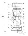
図1は本発明の第1実施例にかかる内視鏡撮像装置の概略構成を示す光軸に沿う断面図である。
第1実施例の内視鏡撮像装置14は、被写体の像を結像する対物光学系と、前記対物光学系を保持する保持枠としてのレンズ枠1’を有している。なお、図1中、2は固体撮像素子枠、F6はフィルタ又はカバーガラス、3は固体撮像素子の撮像面、13は絞りである。
対物光学系は、物体側から順に、物体側が平面で像側が凹面の平凹レンズL1と、絞り7と、フィルタF1と、両凸レンズL2’と、絞り8と、フィルタF2,絞り9と、フィルタF3と、絞り10と、フィルタF4と、絞り11と、両凸レンズL3と物体側に凹面を向けた負メニスカスレンズL4との接合レンズと、絞り12と、フィルタL5を有している。また、両凸レンズL2’とフィルタF2との間には間隔環4が、フィルタ4と両凸レンズL3との間には間隔環5が、物体側に凹面を向けた負メニスカスレンズL4とフィルタF5との間には間隔環6が設けられている。
【0021】
光学フィルタF2の物体側の面には、図8に示した励起光カット特性を有する干渉膜が設けられている。
間隔環4〜6、及び絞り7,8,9,10,11,12の内周部及び外周部、レンズ枠1’の内周部には、光を吸収し反射を防止するための黒色塗装がなされている。
両凸レンズL2’は、その外径がφ1.7となっており、間隔環4,5、光学フィルタF2〜F4、及び絞り8〜11の外径φ2に対して小さく形成されている。
【0022】
このように構成された本実施例の内視鏡撮像装置14では、両凸レンズL2’の像側R面の外周付近で屈折し、対物光学系の光軸と略平行になる光線は両凸レンズL2’の外径と同じφ1.7の領域でのみ発生することになる。よって、励起光カット特性を有する光学フィルタF2の外径φ2とレンズ枠1’の内径との差により生じる隙間を、光軸と平行に直進する光線は発生しない。なお、両凸レンズL2’で屈折し間隔環4の外周部とレンズ枠1’の内周部との隙間に入射する光線は、光軸と平行にならないため、黒色塗装された間隔環4の内周部とレンズ枠1’の内周部との隙間で反射、吸収を繰り返し、光量が大幅に低下し、固体撮像素子3に到達しない。
【0023】
このように、本実施例では、励起光カット特性を有する光学フィルタF2の外径よりも、フィルタF2の物体側に配置した両凸レンズL2’の外径を小さくしており、光学フィルタF2の外周部とレンズ枠1’の内周部との隙間を直進する励起光が発生しない手段をレンズの構成で実現している。このため、物体からの全ての光は、光学フィルタF2の物体側の面に配置された励起光カット特性を有する干渉膜に入射した所定波長の光のみが干渉膜を通過するため、観察に不要な励起光成分を除去できる。
【0024】
なお、光学フィルタF2と両凸レンズL2’の外径差は直径で0.1mm以上あることが望ましい。外径差を0.1mm以上に設定すると、光学フィルタF2、両凸レンズL2’の外径、レンズ枠1’の内径に製造誤差が発生し、或いは、レンズ枠1’の内部で光学フィルタF2や、両凸レンズL2’の位置のバラツキが発生しても、光学フィルタF2の外径φ2とレンズ枠1’の内径との差により生じる隙間を、光軸と平行に直進する光線を発生させないことが可能となる。
【0025】
また、本実施例では光学フィルタF3の物体側の面に図10に示した特性を有する干渉膜を、光学フィルタF4の物体側の面に図11に示した特性を有する干渉膜を、光学フィルタF5の物体側の面に図9に示した特性を有する干渉膜を、光学フィルタF5の像側の面に図12に示した特性を有する干渉膜を設けている。
図13は被写体からの蛍光が固体撮像素子3の面に結像した後、固体撮像素子3で反射し、光学フィルタF2の干渉膜で反射し、再度、固体撮像素子3に到達する光線を示す説明図である。光学フィルタF3,F4の干渉膜においても図13と同様の光線が発生する。
【0026】
図14は被写体からの蛍光が固体撮像素子3の面上に結像した後、固体撮像素子3で反射し、光学フィルタF5の物体側の干渉膜で反射し、再度、固体撮像素子3に到達する光線を示す説明図である。光学フィルタF5の像側の干渉膜においても図14と同様の光線が発生する。前記光線はゴーストフレアと呼ばれ、画像のコントラストを低減させる要因となる。干渉膜や、固体撮像素子3の面は反射率が高いため、前記ゴーストフレアの光強度を低下させる必要がある。本実施例では、図8〜図12に示した特性を有する干渉膜をレンズL3,L4の前後に分散する構成にしているため、図13と図14に示すように、固体撮像素子3の面でのゴーストフレアの位置をずらすことが可能となっている。これにより、ゴーストフレアの光強度を低減することができる。
【0027】
また、本実施例では、図9〜図12に示した特性を有する干渉膜よりも、図8に示した励起光カット特性を有する干渉膜を被写体側に配置している。このため、本実施例の内視鏡撮像装置14によれば、励起光による図9〜図12の干渉膜からの自家蛍光を発生させないことが可能となり、観察能が向上する。
また、対物光学系を保持するレンズ枠1’は一体形成されている。このため、レンズL1〜L4の偏心による結像性能の劣化を低減できる。
【0028】
次に、本実施例の内視鏡撮像装置14を構成する光学部材の数値データを示す。
数値データ1
絞り面:第3,8,10,12,15,19,22面
物体距離=10.4000 像高=0.803 焦点距離=0.847
Fno=2.686 物体側NA=−0.0143 像側NA=0.1862
全長(第1面〜最終面)=7.877

第2実施例
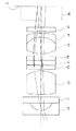
図2は本発明の第2実施例にかかる内視鏡撮像装置の概略構成を示す光軸に沿う断面図である。
第2実施例の内視鏡撮像装置14は、第1実施例の内視鏡撮像装置と比べて、両凸レンズL2”の外径をφ2に変更するとともに、レンズL4’、光学フィルタF5’、間隔環5’、間隔環6’、絞り12’の外径をφ2.4に変更している。また、間隔環5’には、内径をφ1.8の突出部5’aが形成されている。そして、この変更に合わせて、レンズ枠1”の内径を変更している。このように、本実施例では、励起カット特性を有する光学フィルタF2の外径と、光学フィルタF2の物体側に配置した両凸レンズL2”の外径を同じφ2に設定している。
【0030】
このように構成された本実施例の内視鏡撮像装置14では、両凸レンズL2の像側R面の外周付近で屈折した励起光は光軸と平行となり、間隔環4、光学フィルタF2〜F4、及び絞り8,9,10,11の外周部とレンズ枠1”の内周部との隙間を直進する。しかしながら、間隔環5’の突出部5’aは、外径φ2.4、内径φ1.8として形成されているため、φ2相当の前記隙間を直進した励起光を側面で反射、吸収し遮光する。
【0031】
このように、本実施例では、励起光カット特性を有する光学フィルタF2の外径よりも大きな外径を有し、かつ、内径が光学フィルタF2の外径よりも小さい間隔環5’を配置しており、光学フィルタF2の外周部とレンズ枠1”の内周部との隙間を直進する励起光を遮光する手段を保持部材としての間隔環の構成で実現している。このため、物体からの全ての光は、光学フィルタF2の物体側の面に配置された励起光カット特性を有する干渉膜に入射した所定波長の光のみが干渉膜を通過するため、観察に不要な励起光成分を除去できる。
【0032】
なお、光学フィルタF2と間隔環5’の外径差は直径で0.1mm以上、光学フィルタF2の外径と間隔環5’の内径との差は直径で0.1mm以上あることが望ましい。そのように設定すると、光学フィルタF2、間隔環5’に製造誤差が発生し、或いは、レンズ枠1”の内部で光学フィルタF2や、間隔環5’の位置のバラツキが発生した場合でも、光学フィルタF2の外周部とレンズ枠1”の内周部との隙間を直進する励起光を遮光することが可能となる。
【0033】
第3実施例
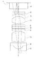
図3は本発明の第3実施例にかかる内視鏡撮像装置の概略構成を示す光軸に沿う断面図である。
第3実施例の内視鏡撮像装置14では、光学フィルタF5’の物体側の面に図8に示した励起光カット特性を有する干渉膜が設けられている。
また、第1実施例の内視鏡撮像装置と比べて、両凸レンズL2”の外径をφ2に変更するとともに、光学フィルタF5’、間隔環6”、絞り12’の外径をφ2.4に変更している。そして、この変更に合わせて、レンズ枠1”’の内径を変更している。
【0034】
このように構成された本実施例の内視鏡撮像装置14では、レンズL4の像側R面の外周付近で屈折し、対物光学系の光軸と略平行になる光線は、レンズL4の外径と同じφ2の領域の大きさで発生することになる。このため、励起光カット特性を有する光学フィルタF5’の外径φ2.4と保持枠1”’の内径との差により生じる隙間を光軸と平行に直進する光線は発生しない。なお、レンズL4で屈折し間隔環6”の外周部とレンズ枠1”’の内周部との隙間に入射する光線は、光軸と平行にならないため、黒色塗装された間隔環6”の外周部とレンズ枠1”’の内周部との隙間で反射、吸収を繰り返し、光量が大幅に低下し、固体撮像素子3に到達しない。
【0035】
このように、本実施例では、励起光カット特性を有する光学フィルタF5’の外径よりも、光学フィルタF5’の物体側に配置したレンズL4の外径を小さくすることで、光学フィルタF5’の外周部とレンズ枠1”’の内周部との隙間を直進する励起光が発生しない手段をレンズの構成で実現している。このため、物体からの全ての光は、光学フィルタF5’の物体側の面に配置された励起光カット特性を有する干渉膜に入射した所定波長の光のみが干渉膜を通過するため、観察に不要な励起光成分を除去できる。
【0036】
なお、光学フィルタF5’とレンズL4の外径差は直径で0.1mm以上あることが望ましい。そのように設定すると、光学フィルタF5’、レンズL4に製造誤差が生じ、或いは、レンズ枠1”’の内部で光学フィルタF5’や、レンズL4の位置のバラツキが発生した場合でも、光学フィルタF5’の外周部とレンズ枠1”’の内周部との隙間を直進する励起光を遮光することが可能となる。
【0037】
また、本実施例では光学フィルタF1の像側の面に図10に示した特性を有する干渉膜を、光学フィルタF2の物体側の面に図11にの特性を有する干渉膜を、光学フィルタF3の物体側の面に図9に示した特性を有する干渉膜を、光学フィルタF4の物体側の面に図12に示した特性を有する干渉膜を設けている。
図15は被写体からの蛍光が固体撮像素子面上に結像し、固体撮像素子で反射し、光学フィルタF1の干渉膜で反射し固体撮像素子に到達する光線を示す説明図である。図15に示すように、光学フィルタF1で発生するゴーストフレアの位置は、図13と図14に示した光学フィルタF2〜F5で発生するゴーストフレアの位置とずれていることがわかる。しかるに、本実施例の内視鏡撮像装置は、光学フィルタF1に干渉膜を配置したので、第1実施例の内視鏡撮像装置よりもゴーストフレアの位置をずらすことが可能となり、ゴーストフレアの光強度をさらに低下させることができる。
【0038】
また、本実施例では、光学フィルタF1〜F5’のうち、結像光線の入射角度が最も小さい光学フィルタF5’に励起光カット特性を有する干渉膜を設けている。このため、光線の入射角度に伴う励起光カット特性の変動を最小限に押さえることが可能となる。そして、図8に示した波長500nm以下をカットする特性をさらに短波長側に設定する、例えば波長490nm以下をカットする特性に設定し、蛍光の光量を増加させることも可能になる。
【0039】
第4実施例
図4は本発明の第4実施例にかかる内視鏡撮像装置の概略構成を示す光軸に沿う断面図である。
第4実施例の内視鏡撮像装置は、第1実施例の内視鏡撮像装置と比べて、両凸レンズL2”の外径をφ2に変更するとともに、保持枠をレンズ枠1””とレンズ枠15の2つに分割している。レンズ枠15は、外径がφ2.4に設定されるとともに、内径がφ1.8に設定された突出部15aを有している。
【0040】
このように構成された本実施例の内視鏡撮像装置では、両凸レンズL2”の像側R面の外周付近で屈折し、対物光学系の光軸と略平行になる光線は、両凸レンズL2の外径と同じφ2の大きさで発生することになる。しかしながら、レンズ枠15の突出部15aの側面で遮光されるため、励起光カット特性を有する光学フィルタF2の外径φ2とレンズ枠15の内径との差により生じる隙間を、光軸と平行に直進する光線は発生しない。なお、両凸レンズL2で屈折しレンズ枠15の外周部とレンズ枠1””の内周部との隙間に入射する光線は、光軸と平行にならないため、黒色塗装されたレンズ枠15の外周部とレンズ枠1””の内周部との隙間で反射、吸収を繰り返し、光量が大幅に低下し、固体撮像素子3に到達しない。
【0041】
このように、本実施例では、外径が励起光カット特性を有する光学フィルタF2の外径よりも大きく、かつ、突出部15aの内径が光学フィルタF2の外径よりも小さいレンズ枠15を配置している。このため、光学フィルタF2の外周部とレンズ枠15の内周部との隙間、又は、レンズ枠1””の内周部とレンズ枠15の外周部との隙間を直進する励起光が発生しない手段を保持部材としてのレンズ枠1””,15の構成で実現している。このため、物体からの全ての光は、光学フィルタF2の物体側の面に配置された励起光カット特性を有する干渉膜に入射した所定波長の光のみが干渉膜を通過するため、観察に不要な励起光成分を除去できる。
【0042】
なお、両凸レンズL2”とレンズ枠15の外径差は直径で0.1mm以上、光学フィルタF2の外径とレンズ枠15の突出部15aの内径との差は直径で0.1mm以上あることが望ましい。このように設定すると、レンズ枠15、両凸レンズL2”の製造誤差、又は、レンズ枠1””の内部で両凸レンズL2”とレンズ枠15の位置のバラツキが発生した場合でも、隙間を直進する励起光が発生させないことが可能となる。
【0043】
なお、レンズ枠15の突出部15aの位置は第4実施例に限定されるものではなく、励起光カット特性を有する干渉膜を有する光学フィルタF2の近傍、すなわち、両凸レンズL2”とレンズL3との間であれば良い。例えば、レンズ枠15の突出部15aの位置を光学フィルタF4とレンズL3との間に配置しても良い。また、光学フィルタF3の外径をφ1.8程度に小さくし、レンズ枠15の突出部15aの位置を光学フィルタF3の位置に配置しても良い。
【0044】
第5実施例
図5は本発明の第5実施例にかかる内視鏡撮像装置の概略構成を示す光軸に沿う断面図である。
第5実施例の内視鏡撮像装置は、第1実施例の内視鏡撮像装置と比べて、両凸レンズL2”の外径をφ2に変更している。また、間隔環5の外周部とレンズ枠1””’の内周部との隙間を埋めるために、間隔環5とレンズL3との間に黒色接着剤16が全周に塗布されている。また、励起カット特性を有する光学フィルタF2の外径と、光学フィルタF2の物体側に配置された両凸レンズL2”の外径を同じφ2に設定している。
【0045】
このように構成された本実施例の内視鏡撮像装置では、両凸レンズL2”の像側R面の外周付近で屈折した励起光は光軸と平行となり、間隔環4、光学フィルタF2〜F4、絞り8,11とレンズ枠1””’との隙間を直進する。しかしながら、間隔環5の外周部とレンズ枠1””’の内周部との隙間を埋めた黒接着剤16により、前記隙間を直進した励起光は反射、吸収され遮光される。
【0046】
このように、本実施例では、間隔環5の外周部とレンズ枠1””’の内周部との隙間を埋める黒接着剤を配置することで、光学フィルタF2の外周部とレンズ枠1の内周部との隙間を直進した励起光を遮光する手段を黒接着剤を用いた保持枠の構成で実現している。このため、物体からの全ての光は、光学フィルタF2の物体側の面に配置された励起光カット特性を有する干渉膜に入射した所定波長の光のみが干渉膜を通過するため、観察に不要な励起光成分を除去できる。
【0047】
なお、黒色接着剤16の位置は本実施例の位置に特定されるものではなく、例えば、間隔環4と両凸レンズL2”との間に黒色接着剤を塗布してもよい。また、光学フィルタF2〜F4の外周部とレンズ枠1””’の内周部との隙間に黒色接着剤を塗布しても良い。
【0048】
本発明は上記各実施例に限定されるものではなく。以下の変形が可能である。また、本実施例1〜5を組み合わせた構成にしても良い。なお、レンズ構成は、上記実施例に限定されるものでは無い。
まず、励起光の波長域、対物光学系に配置されるフィルタの波長域は限定されるものではない。例えば、励起光の波長域400nm〜470nmに対し、対物光学系に配置されるフィルタの透過波長域を500nm〜640nm等に設定しても良い。または、励起光の波長域400nm〜440nmに対し、対物光学系に配置されるフィルタの透過波長域を500nm〜690nm等に設定しても良い。使用される波長域は、内視鏡で観察する部位(食道、胃、大腸)に応じて選択することが望ましい。
【0049】
また、干渉膜だけでなく、吸収型の光学フィルタを用いても良い。
干渉膜は真空蒸着法、又は、イオン製膜法のどちらを使用しても良い。尚、イオン製膜を用いる場合には、基板の変形を押さえるために光学フィルタ基板の厚みは0.4mm以上とすることが望ましい。
また、干渉膜はレンズ面に配置しても良い。
【0050】
また、光学フィルタは、蛍光に関するものに限定されるものでは無い。レーザ治療に用いられる半導体レーザ(波長810nm〜890nm)や、YAGレーザ(波長1064nm)をカットするフィルタも適用可能である。
【0051】
また、レンズ枠は、様々な変形が可能である。レンズ枠の外形も変形可能である。面取り等を入れても良い。
また、間隔環も面取り等の様々な変形が可能である。
【0052】
また、対物光学系の光軸をZ、Zに直行する軸をX,Yとした場合に、光学フィルタF2の物体側の表面形状をZ=A(X3+Y3)にしても良い。このようにすると、特開2000−517号公報に示すように、光学系の被写界深度を拡大することが可能となる。
さらに、固体撮像素子3の代わりにイメージファイバを用いても良い
【0053】
以上説明したように、本発明の内視鏡撮像装置は、特許請求の範囲に記載された発明の他に、以下に示す特徴を備えている。
【0054】
(1)前記光学フィルタの物体側に隣接するレンズの外径を、光学フィルタの外径よりも0.1mm以上小さくしたことを特徴とする請求項3に記載の内視鏡撮像装置。
【0055】
(2)前記保持部材が、前記光学フィルタの外径よりも0.1mm以上大きな外径を有し、かつ、前記光学フィルタの外径よりも0.1mm以上小さな内径を有することを特徴とする請求項4に記載の内視鏡撮像装置。
【0056】
(3)前記保持部材が、前記対物光学系のレンズと光学フィルタとの間隔を設定するように構成されていることを特徴とする請求項4に記載の内視鏡撮像装置。
【0057】
(4)前記保持部材が、前記光学フィルタと前記光学フィルタの被写体側に隣接するレンズとの間に配置され、保持部材の外径が前記レンズの外径よりも大きいことを特徴とする請求項4に記載の内視鏡撮像装置。
【0058】
(5)前記対物光学系が、複数種の光学フィルタを有し、少なくとも1種類の光学フィルタと残りの光学フィルタとの間にレンズを配置したことを特徴とする請求項2に記載の内視鏡撮像装置。
【0059】
(6)前記対物光学系が、複数種の光学フィルタを有し、被写体に照射する照明光の特定波長域の透過率を0.1%以下にする光学フィルタを被写体に最も近い位置に配置したことを特徴とする請求項2に記載の内視鏡撮像装置。
【0060】
【発明の効果】
以上、本発明の内視鏡撮像装置によれば、被写体に照射する照明光の特定波長域の透過率を0.1%以下にする光学フィルタの外周部とそれを保持する保持枠の内周部との隙間を直進し固体撮像素子に到達する照明光を防止するレンズ構成、又は、メカ構成の内視鏡撮像装置を提供することができる。また、ゴーストフレアの影響を低減するのに最適な光学フィルタの配置とした内視鏡撮像装置を提供することができる。
【図面の簡単な説明】
【図1】本発明の第1実施例にかかる内視鏡撮像装置の概略構成を示す光軸に沿う断面図である。
【図2】本発明の第2実施例にかかる内視鏡撮像装置の概略構成を示す光軸に沿う断面図である。
【図3】本発明の第3実施例にかかる内視鏡撮像装置の概略構成を示す光軸に沿う断面図である。
【図4】本発明の第4実施例にかかる内視鏡撮像装置の概略構成を示す光軸に沿う断面図である。
【図5】本発明の第5実施例にかかる内視鏡撮像装置の概略構成を示す光軸に沿う断面図である。
【図6】各実施例の内視鏡撮像装置において光源装置から発せられ、内視鏡の先端部から被写体に照射される励起光の波長特性を示すグラフである。
【図7】各実施例の内視鏡撮像装置の対物光学系に設けられる5種類の干渉膜の総合的な特性を示すグラフである。
【図8】各実施例の内視鏡撮像装置の対物光学系に設けられる一つの干渉膜の特性を示すグラフである。
【図9】各実施例の内視鏡撮像装置の対物光学系に設けられる他の干渉膜の特性を示すグラフである。
【図10】各実施例の内視鏡撮像装置の対物光学系に設けられる更に他の干渉膜の特性を示すグラフである。
【図11】各実施例の内視鏡撮像装置の対物光学系に設けられる更に他の干渉膜の特性を示すグラフである。
【図12】各実施例の内視鏡撮像装置の対物光学系に設けられる更に他の干渉膜の特性を示すグラフである。
【図13】第1実施例の内視鏡撮像装置において、被写体からの蛍光が固体撮像素子面上に結像した後、固体撮像素子で反射し、光学フィルタF2の干渉膜で反射し、再度、固体撮像素子に到達する光線を示す説明図である。
【図14】第1実施例の内視鏡撮像装置において、被写体からの蛍光が固体撮像素子面上に結像した後、固体撮像素子で反射し、光学フィルタF5の物体側の干渉膜で反射し、再度、固体撮像素子に到達する光線を示す説明図である。
【図15】第3実施例の内視鏡撮像装置において、被写体からの蛍光が固体撮像素子面上に結像した後、固体撮像素子で反射し、光学フィルタF1の干渉膜で反射し、再度、固体撮像素子に到達する光線を示す説明図である。
【図16】蛍光を観察する内視鏡システムの従来例の外観図である。
【図17】被写体に照射する照明光の特定波長域の透過率を0.1%以下にする光学フィルタを対物光学系に有する内視鏡撮像装置における一般的に用いられる対物光学系の一例を示す概略構成図である。
【図18】図17の構成において励起光が光学フィルタとレンズ枠の隙間を通過する経路の一例を示す説明図である。
【図19】図17とは別の従来例の対物光学系の被写体像を結像する経路を示す説明図である。
【図20】図19の構成において励起光が光学フィルタの外周部とレンズ枠の内周部との隙間を通過する経路の別の例を示す説明図である。
【符号の説明】
1、1’、1”、1”’、1””、1””’,15 レンズ枠
2 撮像素子枠
3 撮像素子面(又は撮像素子)
4、5、5’、6、6’、6” 間隔環
5’a 突出部
7、8、9、10、11、12、12’、13 絞り
14 内視鏡撮像装置
15a 突出部
16 黒色接着剤
21 内視鏡
22 信号処理装置
23 光源装置
24 モニタ
25 内視鏡先端部
F1、F2、F3、F4、F5、F5’、F7、F8、F9 光学フィルタ
F6 フィルタ又はカバーガラス
L1 レンズ
L2、L2’、L2”、L3 両凸レンズ
L4、L4’ 物体側に凹面を向けた負メニスカスレンズ[0001]
TECHNICAL FIELD OF THE INVENTION
The present invention relates to an endoscope imaging apparatus having an optical filter inside an objective optical system for reducing the transmittance of a specific wavelength range of illumination light to be applied to a subject to 0.1% or less. In particular, the illumination light applied to the subject is excitation light that induces fluorescence, and an endoscope having an optical filter for fluorescence observation inside the objective optical system for reducing the transmittance of the excitation light in the wavelength region to 0.1% or less. The present invention relates to a mirror imaging device.
[0002]
[Prior art]
In recent years, autofluorescence from a living body or a drug is injected into a living body through an endoscope, the fluorescence of the drug is detected as a two-dimensional image, and a disease state such as degeneration of a living tissue or cancer (for example, There are techniques for diagnosing the type of disease and the extent of invasion.
FIG. 16 is an external view showing a conventional example of an endoscope system for observing fluorescence. The endoscope system according to the conventional example includes an
Conventional examples of endoscopes for observing fluorescence are described in, for example, the following
[0003]
[Patent Document 1]
JP-A-9-70384
[Patent Document 2]
JP-A-2002-153414
[Patent Document 3]
JP-A-2002-10969
[0004]
As disclosed in these patent documents, the fluorescence is extremely weak to the excitation light. Therefore, for fluorescence observation, an optical filter that cuts the excitation light and transmits the fluorescence is used for an endoscope imaging apparatus. It must be placed in the objective optical system.
Further,
[0005]
[Patent Document 4]
JP-A-11-223726
[0006]
[Problems to be solved by the invention]
However, the fact that the excitation light passes through the mechanical gap between the optical filter that cuts the excitation light and the holding frame that holds the optical filter, which has a significant effect on observation, and measures to solve it Not mentioned in the example.
FIG. 17 shows a configuration example of a general objective optical system in this type of endoscope imaging apparatus. The objective optical system of the
[0007]
FIG. 18 is an explanatory diagram showing an example of a path through which the excitation light passes through the gap between the optical filter and the lens frame in the configuration of FIG. In FIG. 18, the lens frame and the solid-state imaging device frame are omitted. The light beam refracted near the outer periphery of the image-side R surface of the lens L2 becomes a light beam that is substantially parallel to the optical axis of the objective optical system and corresponds to the height of the outer diameter of the optical filter. 8, 9, 10, 11 and the gap between the outer peripheral portions of the
[0008]
For example, assuming that the outer diameters of the optical filters F2 to F4, the
[0009]
FIG. 19 is an explanatory view showing a path for forming a subject image of a conventional objective optical system different from that of FIG. 17, and FIG. 20 is a path in which excitation light passes through a gap between an optical filter and a lens frame in the configuration of FIG. It is explanatory drawing which shows another example of. Note that the lens frame and the solid-state imaging device holding are omitted. In the example of FIG. 19, the objective optical system has lenses L5 to L7, optical filters F7 to F9, and the like inserted in a lens frame not shown.
In the example of FIG. 19, when any one of the optical filters F7 to F9 is used as an excitation light cut filter, the light refracted near the outer periphery of the image side R surface of the lens L5 becomes substantially parallel to the optical axis of the objective optical system, The straight line travels through the gap between the outer peripheral portions of the optical filters F7 to F9 and the inner peripheral portion of the lens frame (not shown). Thus, the above problem is not limited to a specific lens configuration. That is, the above problem occurs when the outer diameter of the lens on the object side close to the excitation light cut filter is equal to or larger than the outer diameter of the excitation light cut filter.
[0010]
Furthermore, as another factor that lowers the contrast of the fluorescent image, part of the fluorescent light transmitted through the excitation light cut filter and formed on the imaging surface of the solid-state image sensor repeatedly reflects between the imaging surface and the optical filter. There is a phenomenon that the image is re-imaged on the imaging surface by following another path.
[0011]
As described above, in order to obtain a fluorescent image with good contrast, it is necessary to solve a new technical problem in addition to the conventionally known technology.
The present invention has been made in view of the above-described problems, and has an outer peripheral portion of an optical filter and a holding frame that holds the optical filter that reduce the transmittance of illumination light to be applied to a subject in a specific wavelength range to 0.1% or less. It is an object of the present invention to provide an endoscope imaging apparatus that prevents illumination light traveling straight through a gap with an inner peripheral portion and reaching a solid-state imaging device. It is another object of the present invention to provide an endoscope imaging apparatus that reduces the effects of ghost flare.
[0012]
[Means for Solving the Problems]
In order to achieve the above object, an endoscope imaging apparatus according to the present invention includes an objective optical system that forms an image of a subject and an endoscope imaging apparatus that has a holding frame that holds the objective optical system. An optical filter for reducing the transmittance of the illumination light in a specific wavelength range to 0.1% or less inside the objective optical system, and an outer peripheral portion of the optical filter and an inner periphery of the holding frame for holding the optical filter. A light transmitting means for preventing light passing through a gap between the light transmitting section and the light transmitting section.
[0013]
An endoscope imaging apparatus according to the present invention is an endoscope imaging apparatus having an objective optical system that forms an image of a subject and a holding frame that holds the objective optical system, wherein the excitation light that induces fluorescence of the subject is provided. Excitation light passing through a gap between an outer peripheral portion of the optical filter and an inner peripheral portion of the holding frame that holds the optical filter, the optical filter having an optical filter that reduces the transmittance of the optical filter to 0.1% or less. This is characterized in that a passing light preventing means for preventing the occurrence of light is provided.
[0014]
Further, in the endoscope imaging apparatus according to the present invention, an outer diameter of a lens adjacent to the object side of the optical filter in the objective optical system is smaller than an outer diameter of the optical filter.
[0015]
Further, in the endoscope imaging apparatus according to the present invention, a holding member whose outer diameter is larger than the outer diameter of the optical filter and whose inner diameter is smaller than the outer diameter of the optical filter is disposed near the optical filter. It is characterized by doing.
[0016]
BEST MODE FOR CARRYING OUT THE INVENTION
Prior to the description of the embodiments, the operation and effect of the present invention will be described.
As in the endoscope imaging apparatus of the present invention, provided with a passing light preventing means for preventing light passing through a gap between the outer peripheral portion of the optical filter and the inner peripheral portion of the holding frame holding the optical filter, Light unnecessary for observation can be removed.
[0017]
Further, in the endoscope imaging apparatus of the present invention, if the outer diameter of the lens adjacent to the object side of the optical filter in the objective optical system is smaller than the outer diameter of the optical filter, the outer peripheral portion of the optical filter and the optical filter are separated. A lens configuration that does not generate light that travels straight through the gap between the holding frame and the inner peripheral portion can be realized.
[0018]
Further, in the endoscope imaging apparatus of the present invention, if a holding member whose outer diameter is larger than the outer diameter of the optical filter and whose inner diameter is smaller than the outer diameter of the optical filter is disposed near the optical filter, A mechanical configuration in which light does not enter the gap between the outer periphery of the filter and the inner periphery of the holding frame holding the optical filter can be realized. In addition, if the holding member is disposed closer to the image side than the optical filter, it is possible to realize a mechanical configuration that blocks light that has traveled straight through the gap between the outer periphery of the optical filter and the inner periphery of the holding frame that holds the optical filter.
[0019]
【Example】
FIG. 6 is a graph showing the wavelength characteristics of the excitation light emitted from the light source device in the endoscope imaging apparatus of each of the following embodiments and applied to the subject from the end of the endoscope. In the drawing, the transmittance “1” indicates that 100% of light is transmitted.
As shown in FIG. 6, in the endoscope imaging apparatus of each embodiment, excitation light in a wavelength range of 400 nm to 470 nm is illuminated. The objective optical system for picking up an image of a subject is provided with five types of interference films shown in FIGS. 8 to 12, and the overall characteristics of these interference films are shown in FIG. It has a characteristic of transmitting light only in the wavelength range of 500 to 620 nm. As a result, the excitation light having a wavelength of 500 nm or less is cut (the transmittance is reduced to 0.1% or less), and at the same time, unnecessary fluorescence generated in a wavelength region of 620 nm or more and near-infrared light emitted from a living body are obtained. To improve diagnostic performance.
[0020]
First embodiment
FIG. 1 is a sectional view along an optical axis showing a schematic configuration of an endoscope imaging apparatus according to a first embodiment of the present invention.
The
The objective optical system includes, in order from the object side, a plano-concave lens L1 having a flat surface on the object side and a concave surface on the image side, a
[0021]
An interference film having the excitation light cutoff characteristic shown in FIG. 8 is provided on the object-side surface of the optical filter F2.
Black coating for absorbing light and preventing reflection is applied to the inner and outer peripheral portions of the spacing rings 4 to 6, the
The outer diameter of the biconvex lens L2 'is 1.7, which is smaller than the
[0022]
In the
[0023]
As described above, in the present embodiment, the outer diameter of the biconvex lens L2 ′ disposed on the object side of the filter F2 is smaller than the outer diameter of the optical filter F2 having the excitation light cutting characteristic. A means that does not generate excitation light that travels straight through the gap between the portion and the inner peripheral portion of the lens frame 1 'is realized by a lens configuration. For this reason, all light from the object is unnecessary for observation because only light of a predetermined wavelength that has entered the interference film having the excitation light cut characteristic disposed on the object-side surface of the optical filter F2 passes through the interference film. Excitation light components can be removed.
[0024]
The difference between the outer diameters of the optical filter F2 and the biconvex lens L2 'is desirably 0.1 mm or more in diameter. If the outer diameter difference is set to 0.1 mm or more, a manufacturing error occurs in the outer diameter of the optical filter F2, the biconvex lens L2 ′, and the inner diameter of the
[0025]
In this embodiment, an interference film having the characteristics shown in FIG. 10 is provided on the object-side surface of the optical filter F3, and an interference film having the characteristics shown in FIG. 11 is provided on the object-side surface of the optical filter F4. An interference film having the characteristics shown in FIG. 9 is provided on the object-side surface of F5, and an interference film having the characteristics shown in FIG. 12 is provided on the image-side surface of the optical filter F5.
FIG. 13 shows light rays that are reflected from the solid-
[0026]
FIG. 14 shows that after the fluorescence from the subject forms an image on the surface of the solid-
[0027]
In this embodiment, an interference film having the excitation light cutoff characteristic shown in FIG. 8 is arranged closer to the subject than an interference film having the characteristics shown in FIGS. 9 to 12. For this reason, according to the
The lens frame 1 'for holding the objective optical system is integrally formed. Therefore, it is possible to reduce the deterioration of the imaging performance due to the eccentricity of the lenses L1 to L4.
[0028]
Next, numerical data of optical members constituting the
Aperture surface: 3, 8, 10, 12, 15, 19, 22
Object distance = 10.4000 Image height = 0.803 Focal length = 0.847
Fno = 2.686 Object side NA = −0.0143 Image side NA = 0.1862
Overall length (first surface to last surface) = 7.877
Second embodiment
FIG. 2 is a sectional view along the optical axis showing a schematic configuration of an endoscope imaging apparatus according to a second embodiment of the present invention.
The
[0030]
In the
[0031]
As described above, in the present embodiment, the
[0032]
Preferably, the difference between the outer diameter of the optical filter F2 and the spacing ring 5 'is 0.1 mm or more in diameter, and the difference between the outer diameter of the optical filter F2 and the inner diameter of the spacing ring 5' is 0.1 mm or more. With such a setting, even if a manufacturing error occurs in the optical filter F2 and the
[0033]
Third embodiment
FIG. 3 is a sectional view along an optical axis showing a schematic configuration of an endoscope imaging apparatus according to a third embodiment of the present invention.
In the
Further, as compared with the endoscope imaging apparatus of the first embodiment, the outer diameter of the biconvex lens L2 ″ is changed to φ2, and the outer diameters of the optical filter F5 ′, the
[0034]
In the
[0035]
As described above, in the present embodiment, by making the outer diameter of the lens L4 disposed on the object side of the optical filter F5 'smaller than the outer diameter of the optical filter F5' having the excitation light cutting characteristic, the optical filter F5 ' A means that does not generate excitation light that travels straight through the gap between the outer peripheral portion of the lens frame and the inner peripheral portion of the
[0036]
It is desirable that the difference between the outer diameters of the optical filter F5 'and the lens L4 be 0.1 mm or more. With such a setting, even when a manufacturing error occurs in the optical filter F5 ′ and the lens L4, or when the position of the optical filter F5 ′ and the lens L4 varies within the
[0037]
In the present embodiment, an interference film having the characteristics shown in FIG. 10 is provided on the image-side surface of the optical filter F1, and an interference film having the characteristics shown in FIG. 11 is provided on the object-side surface of the optical filter F2. An interference film having the characteristics shown in FIG. 9 is provided on the object-side surface of the optical filter F4, and an interference film having the characteristics shown in FIG. 12 is provided on the object-side surface of the optical filter F4.
FIG. 15 is an explanatory diagram illustrating light rays that form an image of fluorescent light from a subject on the solid-state imaging device surface, are reflected by the solid-state imaging device, are reflected by the interference film of the optical filter F1, and reach the solid-state imaging device. As shown in FIG. 15, it can be seen that the position of the ghost flare generated in the optical filter F1 is shifted from the position of the ghost flare generated in the optical filters F2 to F5 shown in FIGS. However, in the endoscope imaging apparatus of the present embodiment, since the interference film is arranged on the optical filter F1, the position of the ghost flare can be shifted from that of the endoscope imaging apparatus of the first embodiment, and the ghost flare can be reduced. The light intensity can be further reduced.
[0038]
Further, in the present embodiment, an interference film having excitation light cut characteristics is provided in the optical filter F5 'having the smallest incident angle of the imaging light among the optical filters F1 to F5'. For this reason, it is possible to minimize the fluctuation of the excitation light cutting characteristic due to the incident angle of the light beam. Then, the characteristic of cutting the wavelength of 500 nm or less shown in FIG. 8 can be set to a shorter wavelength side, for example, the characteristic of cutting the wavelength of 490 nm or less can be set to increase the amount of fluorescent light.
[0039]
Fourth embodiment
FIG. 4 is a sectional view along an optical axis showing a schematic configuration of an endoscope imaging apparatus according to a fourth embodiment of the present invention.
The endoscope imaging apparatus according to the fourth embodiment differs from the endoscope imaging apparatus according to the first embodiment in that the outer diameter of the biconvex lens L2 ″ is changed to φ2 and the holding frame is formed as a
[0040]
In the endoscope imaging apparatus according to the present embodiment configured as described above, the light that is refracted near the outer periphery of the image-side R surface of the biconvex lens L2 ″ and becomes substantially parallel to the optical axis of the objective optical system is the biconvex lens L2. However, since the light is shielded by the side surface of the protruding
[0041]
As described above, in the present embodiment, the
[0042]
The difference between the outer diameter of the biconvex lens L2 ″ and the
[0043]
The position of the protruding
[0044]
Fifth embodiment
FIG. 5 is a sectional view along the optical axis showing a schematic configuration of an endoscope imaging apparatus according to a fifth embodiment of the present invention.
The endoscope imaging apparatus of the fifth embodiment differs from the endoscope imaging apparatus of the first embodiment in that the outer diameter of the biconvex lens L2 ″ is changed to φ2. A
[0045]
In the endoscope imaging apparatus of the present embodiment configured as described above, the excitation light refracted near the outer periphery of the image-side R surface of the biconvex lens L2 ″ becomes parallel to the optical axis, the
[0046]
As described above, in the present embodiment, the black adhesive that fills the gap between the outer peripheral portion of the
[0047]
The position of the
[0048]
The present invention is not limited to the above embodiments. The following modifications are possible. Further, a configuration in which the first to fifth embodiments are combined may be adopted. The lens configuration is not limited to the above embodiment.
First, the wavelength range of the excitation light and the wavelength range of the filter arranged in the objective optical system are not limited. For example, the transmission wavelength range of the filter arranged in the objective optical system may be set to 500 nm to 640 nm for the wavelength range of 400 nm to 470 nm of the excitation light. Alternatively, the transmission wavelength range of the filter arranged in the objective optical system may be set to 500 nm to 690 nm for the wavelength range of 400 nm to 440 nm of the excitation light. The wavelength range to be used is desirably selected according to the site (esophagus, stomach, colon) to be observed with an endoscope.
[0049]
Further, not only the interference film but also an absorption type optical filter may be used.
The interference film may be formed by a vacuum deposition method or an ion film formation method. In the case where an ion film is used, the thickness of the optical filter substrate is desirably 0.4 mm or more to suppress deformation of the substrate.
Further, the interference film may be arranged on the lens surface.
[0050]
Further, the optical filter is not limited to one related to fluorescence. A semiconductor laser (wavelength 810 nm to 890 nm) used for laser treatment and a filter for cutting a YAG laser (wavelength 1064 nm) are also applicable.
[0051]
Further, the lens frame can be variously deformed. The outer shape of the lens frame can also be changed. You may put a chamfer etc.
In addition, various modifications such as chamfering of the spacing ring are possible.
[0052]
When the optical axis of the objective optical system is Z, and the axes perpendicular to Z are X and Y, the object-side surface shape of the optical filter F2 is Z = A (X3+ Y3). This makes it possible to increase the depth of field of the optical system as disclosed in Japanese Patent Application Laid-Open No. 2000-517.
Further, an image fiber may be used instead of the solid-
[0053]
As described above, the endoscope imaging apparatus of the present invention has the following features in addition to the invention described in the claims.
[0054]
(1) The endoscope imaging apparatus according to
[0055]
(2) The holding member has an outer diameter that is 0.1 mm or more larger than the outer diameter of the optical filter, and has an inner diameter that is 0.1 mm or more smaller than the outer diameter of the optical filter. The endoscope imaging device according to
[0056]
(3) The endoscope imaging apparatus according to
[0057]
(4) The holding member is disposed between the optical filter and a lens adjacent to the object side of the optical filter, and an outer diameter of the holding member is larger than an outer diameter of the lens. 5. The endoscope imaging device according to 4.
[0058]
(5) The endoscope according to
[0059]
(6) The objective optical system has a plurality of types of optical filters, and the optical filter that makes the transmittance of illumination light applied to the subject in a specific wavelength range 0.1% or less is arranged at a position closest to the subject. The endoscope imaging apparatus according to
[0060]
【The invention's effect】
As described above, according to the endoscope imaging apparatus of the present invention, the outer periphery of the optical filter that makes the transmittance of the specific wavelength region of the illumination light irradiating the subject 0.1% or less and the inner periphery of the holding frame that holds the optical filter. It is possible to provide an endoscope imaging apparatus having a lens configuration or a mechanical configuration that prevents illumination light that travels straight through a gap with the unit and reaches the solid-state imaging device. Further, it is possible to provide an endoscope imaging apparatus in which an optical filter optimally arranged to reduce the influence of ghost flare is provided.
[Brief description of the drawings]
FIG. 1 is a cross-sectional view along an optical axis showing a schematic configuration of an endoscope imaging apparatus according to a first embodiment of the present invention.
FIG. 2 is a cross-sectional view along an optical axis showing a schematic configuration of an endoscope imaging apparatus according to a second embodiment of the present invention.
FIG. 3 is a sectional view along an optical axis showing a schematic configuration of an endoscope imaging apparatus according to a third embodiment of the present invention.
FIG. 4 is a sectional view along an optical axis showing a schematic configuration of an endoscope imaging apparatus according to a fourth embodiment of the present invention.
FIG. 5 is a sectional view along an optical axis showing a schematic configuration of an endoscope imaging apparatus according to a fifth embodiment of the present invention.
FIG. 6 is a graph showing wavelength characteristics of excitation light emitted from the light source device in the endoscope imaging apparatus of each embodiment and emitted to the subject from the end of the endoscope.
FIG. 7 is a graph showing the overall characteristics of five types of interference films provided in the objective optical system of the endoscope imaging apparatus of each embodiment.
FIG. 8 is a graph showing characteristics of one interference film provided in the objective optical system of the endoscope imaging apparatus of each embodiment.
FIG. 9 is a graph showing characteristics of another interference film provided in the objective optical system of the endoscope imaging apparatus of each embodiment.
FIG. 10 is a graph showing characteristics of still another interference film provided in the objective optical system of the endoscope imaging apparatus of each embodiment.
FIG. 11 is a graph showing characteristics of still another interference film provided in the objective optical system of the endoscope imaging apparatus of each embodiment.
FIG. 12 is a graph showing characteristics of still another interference film provided in the objective optical system of the endoscope imaging apparatus of each embodiment.
FIG. 13 is a cross-sectional view of the endoscope imaging apparatus according to the first embodiment. FIG. 4 is an explanatory diagram showing light rays reaching a solid-state imaging device.
FIG. 14 is a cross-sectional view of the endoscope imaging apparatus according to the first embodiment, in which fluorescence from a subject forms an image on the surface of a solid-state imaging device, and is reflected by the solid-state imaging device; FIG. 4 is an explanatory diagram showing light rays that reach the solid-state imaging device again.
FIG. 15 In the endoscope imaging apparatus according to the third embodiment, after the fluorescent light from the subject forms an image on the surface of the solid-state imaging device, the fluorescence is reflected by the solid-state imaging device, reflected by the interference film of the optical filter F1, and again. FIG. 4 is an explanatory diagram showing light rays reaching a solid-state imaging device.
FIG. 16 is an external view of a conventional example of an endoscope system for observing fluorescence.
FIG. 17 shows an example of an objective optical system generally used in an endoscope imaging apparatus having an optical filter in an objective optical system for reducing the transmittance of illumination light to be applied to a subject in a specific wavelength range to 0.1% or less. FIG.
18 is an explanatory diagram showing an example of a path through which the excitation light passes through a gap between the optical filter and the lens frame in the configuration of FIG. 17;
FIG. 19 is an explanatory diagram showing a path for forming a subject image of a conventional objective optical system different from FIG. 17;
20 is an explanatory diagram showing another example of a path through which the excitation light passes through a gap between the outer peripheral portion of the optical filter and the inner peripheral portion of the lens frame in the configuration of FIG. 19;
[Explanation of symbols]
1, 1 ', 1 ", 1"', 1 "", 1 "" ', 15 lens frames
2 Image sensor frame
3 Image sensor surface (or image sensor)
4, 5, 5 ', 6, 6', 6 "spacing rings
5'a protrusion
7, 8, 9, 10, 11, 12, 12 ', 13 aperture
14 Endoscope imaging device
15a Projection
16 black adhesive
21 Endoscope
22 Signal processing device
23 Light source device
24 monitors
25 Endoscope tip
F1, F2, F3, F4, F5, F5 ', F7, F8, F9 Optical filters
F6 filter or cover glass
L1 lens
L2, L2 ', L2 ", L3 biconvex lens
L4, L4 'Negative meniscus lens with concave surface facing object side
Claims (4)
被写体に照射する照明光の特定波長域の透過率を0.1%以下にする光学フィルタを前記対物光学系の内部に有するとともに、
前記光学フィルタの外周部と該光学フィルタを保持する前記保持枠の内周部との隙間を通過する光を防止する通過光防止手段を設けたことを特徴とする内視鏡撮像装置。In an objective optical system that forms an image of a subject and an endoscope imaging apparatus that has a holding frame that holds the objective optical system,
An optical filter for reducing the transmittance of the specific wavelength region of the illumination light irradiating the subject to 0.1% or less, inside the objective optical system,
An endoscope imaging apparatus, further comprising: a passing light preventing unit that prevents light passing through a gap between an outer peripheral portion of the optical filter and an inner peripheral portion of the holding frame that holds the optical filter.
被写体の蛍光を誘発する励起光の透過率を0.1%以下にする光学フィルタを前記対物光学系に有するとともに、
前記光学フィルタの外周部と該光学フィルタを保持する前記保持枠の内周部との隙間を通過する励起光を防止する通過光防止手段を設けたことを特徴とする内視鏡撮像装置。In an objective optical system that forms an image of a subject and an endoscope imaging apparatus that has a holding frame that holds the objective optical system,
An optical filter for reducing the transmittance of excitation light that induces fluorescence of the subject to 0.1% or less in the objective optical system;
An endoscope imaging apparatus, further comprising: a passing light preventing unit that prevents excitation light passing through a gap between an outer peripheral portion of the optical filter and an inner peripheral portion of the holding frame that holds the optical filter.
Priority Applications (2)
| Application Number | Priority Date | Filing Date | Title |
|---|---|---|---|
| JP2003141889A JP2004344230A (en) | 2003-05-20 | 2003-05-20 | Imaging device of endoscope |
| US10/846,665 US7093945B2 (en) | 2003-05-20 | 2004-05-17 | Imaging apparatus for endoscopes |
Applications Claiming Priority (1)
| Application Number | Priority Date | Filing Date | Title |
|---|---|---|---|
| JP2003141889A JP2004344230A (en) | 2003-05-20 | 2003-05-20 | Imaging device of endoscope |
Publications (2)
| Publication Number | Publication Date |
|---|---|
| JP2004344230A true JP2004344230A (en) | 2004-12-09 |
| JP2004344230A5 JP2004344230A5 (en) | 2005-10-27 |
Family
ID=33447455
Family Applications (1)
| Application Number | Title | Priority Date | Filing Date |
|---|---|---|---|
| JP2003141889A Pending JP2004344230A (en) | 2003-05-20 | 2003-05-20 | Imaging device of endoscope |
Country Status (2)
| Country | Link |
|---|---|
| US (1) | US7093945B2 (en) |
| JP (1) | JP2004344230A (en) |
Cited By (8)
| Publication number | Priority date | Publication date | Assignee | Title |
|---|---|---|---|---|
| EP2078976A1 (en) | 2008-01-08 | 2009-07-15 | Olympus Medical Systems Corporation | Objective optical system for endoscopes and endoscope system using the same |
| KR20100074078A (en) * | 2008-12-23 | 2010-07-01 | 안테리온 인터내셔날 비 브이 | Optical unit |
| JP2013076844A (en) * | 2011-09-30 | 2013-04-25 | Fujifilm Corp | Photographic lens unit for endoscope and camera module |
| JP2013076856A (en) * | 2011-09-30 | 2013-04-25 | Fujifilm Corp | Photographic lens unit for endoscope and camera module |
| JP2013250577A (en) * | 2013-09-02 | 2013-12-12 | Fujifilm Corp | Photographic lens unit for endoscope and camera module |
| JP2017531491A (en) * | 2014-10-07 | 2017-10-26 | ボストン サイエンティフィック サイムド,インコーポレイテッドBoston Scientific Scimed,Inc. | Endoscope laser light filter assembly |
| JP2019148675A (en) * | 2018-02-27 | 2019-09-05 | オリンパス株式会社 | Endoscope objective optical system |
| WO2020067385A1 (en) * | 2018-09-28 | 2020-04-02 | パナソニックi-PROセンシングソリューションズ株式会社 | Endoscope |
Families Citing this family (9)
| Publication number | Priority date | Publication date | Assignee | Title |
|---|---|---|---|---|
| DE102004032179A1 (en) * | 2004-07-02 | 2006-01-19 | Robert Bosch Gmbh | Lens with vehicle-compatible seal configuration |
| US20080020201A1 (en) * | 2006-07-20 | 2008-01-24 | Lisa Yvonne Winckler | Composite, Color Corrected Films Comprising an Aluminum Oxide Coating |
| JP4308233B2 (en) * | 2006-09-01 | 2009-08-05 | オリンパスメディカルシステムズ株式会社 | Imaging module for endoscope |
| CN101630058B (en) * | 2008-07-18 | 2011-03-23 | 上海澳华光电内窥镜有限公司 | Objective lens of endoscope |
| JP6102929B2 (en) * | 2012-09-14 | 2017-03-29 | コニカミノルタ株式会社 | Optical lens, optical lens unit, and imaging apparatus |
| KR101883033B1 (en) * | 2015-05-27 | 2018-07-27 | 삼성전기주식회사 | Lens module |
| CN105167735B (en) * | 2015-09-30 | 2017-08-22 | 青岛奥美克医疗科技有限公司 | A kind of method of ghost image in elimination endoscopic system |
| KR101988602B1 (en) * | 2017-09-14 | 2019-06-13 | 주식회사 나오텍 | Lens assembly for TOF |
| DE102021106836A1 (en) * | 2020-10-02 | 2022-04-07 | Karl Storz Se & Co. Kg | Optical filter system for a video endoscope, display system and video endoscope |
Family Cites Families (8)
| Publication number | Priority date | Publication date | Assignee | Title |
|---|---|---|---|---|
| JPS62172319A (en) * | 1986-01-24 | 1987-07-29 | Canon Inc | Composite filter |
| JPH05341167A (en) * | 1992-06-08 | 1993-12-24 | Matsushita Electric Ind Co Ltd | Lens holding member and formation of thin film |
| JP3467131B2 (en) | 1994-09-21 | 2003-11-17 | ペンタックス株式会社 | Electronic endoscope device for fluorescence diagnosis |
| JPH11223726A (en) | 1997-10-28 | 1999-08-17 | Asahi Optical Co Ltd | Filter for fluorescence and fluorescent observation endoscope device |
| JP2002010969A (en) | 2000-04-24 | 2002-01-15 | Fuji Photo Film Co Ltd | Fluorescent endoscope device |
| JP2002153414A (en) | 2000-11-17 | 2002-05-28 | Asahi Optical Co Ltd | Electron endoscope and electron endoscope system |
| JP3985466B2 (en) * | 2001-06-07 | 2007-10-03 | フジノン株式会社 | Endoscope lens device |
| JP3875063B2 (en) * | 2001-10-26 | 2007-01-31 | 日本電産コパル株式会社 | Lens barrel |
-
2003
- 2003-05-20 JP JP2003141889A patent/JP2004344230A/en active Pending
-
2004
- 2004-05-17 US US10/846,665 patent/US7093945B2/en active Active
Cited By (14)
| Publication number | Priority date | Publication date | Assignee | Title |
|---|---|---|---|---|
| JP2009160257A (en) * | 2008-01-08 | 2009-07-23 | Olympus Medical Systems Corp | Objective optical system for endoscopes and endoscope system using the same |
| EP2078976A1 (en) | 2008-01-08 | 2009-07-15 | Olympus Medical Systems Corporation | Objective optical system for endoscopes and endoscope system using the same |
| KR101694537B1 (en) * | 2008-12-23 | 2017-01-09 | 안테리온 인터내셔날 비 브이 | Optical unit |
| KR20100074078A (en) * | 2008-12-23 | 2010-07-01 | 안테리온 인터내셔날 비 브이 | Optical unit |
| JP2010152358A (en) * | 2008-12-23 | 2010-07-08 | Anteryon Internatl Bv | Optical unit |
| JP2013076844A (en) * | 2011-09-30 | 2013-04-25 | Fujifilm Corp | Photographic lens unit for endoscope and camera module |
| JP2013076856A (en) * | 2011-09-30 | 2013-04-25 | Fujifilm Corp | Photographic lens unit for endoscope and camera module |
| JP2013250577A (en) * | 2013-09-02 | 2013-12-12 | Fujifilm Corp | Photographic lens unit for endoscope and camera module |
| JP2017531491A (en) * | 2014-10-07 | 2017-10-26 | ボストン サイエンティフィック サイムド,インコーポレイテッドBoston Scientific Scimed,Inc. | Endoscope laser light filter assembly |
| JP2019148675A (en) * | 2018-02-27 | 2019-09-05 | オリンパス株式会社 | Endoscope objective optical system |
| WO2020067385A1 (en) * | 2018-09-28 | 2020-04-02 | パナソニックi-PROセンシングソリューションズ株式会社 | Endoscope |
| JPWO2020067385A1 (en) * | 2018-09-28 | 2021-09-02 | パナソニックi−PROセンシングソリューションズ株式会社 | Endoscope |
| JP7208253B2 (en) | 2018-09-28 | 2023-01-18 | i-PRO株式会社 | Endoscope |
| JP7388767B2 (en) | 2018-09-28 | 2023-11-29 | i-PRO株式会社 | Endoscope |
Also Published As
| Publication number | Publication date |
|---|---|
| US7093945B2 (en) | 2006-08-22 |
| US20040233538A1 (en) | 2004-11-25 |
Similar Documents
| Publication | Publication Date | Title |
|---|---|---|
| JP2004344230A (en) | Imaging device of endoscope | |
| JP5558058B2 (en) | Endoscopic endoscope | |
| US8409081B2 (en) | Illumination light application structure and endoscope provided with the same | |
| EP2385406A1 (en) | Optical element and optical unit using the same | |
| JP5380690B2 (en) | Endoscope objective optical system and endoscope system using the same | |
| JPH10239594A (en) | Electronic endoscope | |
| JP7388767B2 (en) | Endoscope | |
| JP4504438B2 (en) | Illumination light irradiation structure and endoscope provided with the same | |
| JPH0511196A (en) | Visual field direction conversion optical system for endoscope | |
| JP4137726B2 (en) | Imaging device | |
| JP2005342034A (en) | Light source device for endoscope | |
| US11119306B2 (en) | Image pickup optical system, endoscope, and image pickup apparatus | |
| JP2009042519A (en) | Objective lens | |
| JP3044588B2 (en) | Objective lens for endoscope | |
| JP6865463B2 (en) | Image guide device and endoscope | |
| JPH1176146A (en) | Optical device | |
| US20230341668A1 (en) | An optical element | |
| WO2012157552A1 (en) | Probe | |
| JPH10113329A (en) | Objective optical system of endoscope | |
| JP6240391B2 (en) | Laparoscope | |
| EP4298983A1 (en) | Beam splitting device for a distal end section of an endoscope, objective system and endoscope | |
| JP4495521B2 (en) | Endoscope observation unit and endoscope | |
| JP2015148767A (en) | Image formation lens system for endoscope device and endoscope device | |
| JPH1054945A (en) | Endoscopic illuminating optical system | |
| JP2009225947A (en) | Illumination optics for endoscope and its assembly method |
Legal Events
| Date | Code | Title | Description |
|---|---|---|---|
| A521 | Request for written amendment filed |
Free format text: JAPANESE INTERMEDIATE CODE: A523 Effective date: 20050705 |
|
| A621 | Written request for application examination |
Free format text: JAPANESE INTERMEDIATE CODE: A621 Effective date: 20050705 |
|
| A977 | Report on retrieval |
Free format text: JAPANESE INTERMEDIATE CODE: A971007 Effective date: 20080125 |
|
| A131 | Notification of reasons for refusal |
Free format text: JAPANESE INTERMEDIATE CODE: A131 Effective date: 20080205 |
|
| A521 | Request for written amendment filed |
Free format text: JAPANESE INTERMEDIATE CODE: A523 Effective date: 20080407 |
|
| A02 | Decision of refusal |
Free format text: JAPANESE INTERMEDIATE CODE: A02 Effective date: 20080603 |