JP2004339992A - Fuel injector - Google Patents
Fuel injector Download PDFInfo
- Publication number
- JP2004339992A JP2004339992A JP2003135914A JP2003135914A JP2004339992A JP 2004339992 A JP2004339992 A JP 2004339992A JP 2003135914 A JP2003135914 A JP 2003135914A JP 2003135914 A JP2003135914 A JP 2003135914A JP 2004339992 A JP2004339992 A JP 2004339992A
- Authority
- JP
- Japan
- Prior art keywords
- connection
- pipe
- valve casing
- rotation positioning
- fuel injection
- Prior art date
- Legal status (The legal status is an assumption and is not a legal conclusion. Google has not performed a legal analysis and makes no representation as to the accuracy of the status listed.)
- Pending
Links
Images


Abstract
Description
【0001】
【発明の属する技術分野】
本発明は、燃料タンク内の燃料を燃料配管を経て燃料噴射弁に供給し、燃料噴射弁より内燃機関の吸気側に燃料を噴射させる燃料噴射装置に関し、特に、燃料配管と燃料噴射弁との接続構造に係わる。
【0002】
【従来の技術】
従来より燃料配管と燃料噴射弁との接続構造に関する技術が種々提案されている。特表平4−500259号公報は、その一例としての燃料噴射装置を開示する。
【0003】
上記公報の燃料噴射装置100は、図10及び図11に示すように、燃料タンク側に接続された燃料配管101と、内燃機関の吸気管側に固定された燃料噴射弁102と、燃料配管101及び燃料噴射弁102に嵌合される接続用クリップ103とを備えている。
【0004】
燃料配管101の底面側には円筒状の接続管104が突設され、この接続管104の内周面が後述する弁ケーシング108の接続部108aを嵌合により接続する嵌合孔105になっている。また、接続管104の外周面には回転位置決め用突起106が突設されていると共に、該接続管104の外周面の先端には抜け止め用フランジ部107が突設されている。
【0005】
燃料噴射弁102の円筒状の弁ケーシング108の一端側(燃料流入側)は接続部108aとして形成されている。この接続部108aの外周面には回転位置決め用突起109が突設されていると共に、環状の抜け止め用周溝110が形成されている。
【0006】
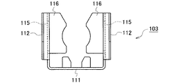
接続用クリップ103は、図12〜図14に示すように、連結部111と、この連結部111の両端より延設された一対のアーム部112,112とを備えている。連結部111の上下方向には回転位置決め用凹部113,114がそれぞれ設けられている。一対のアーム部112,112には抜け止め用溝孔115がそれぞれ形成されていると共に、一対のアーム部112,112の内側には内面円弧状を有する抜け止め用嵌合片116がそれぞれ設けられている。
【0007】
次に、燃料配管101と燃料噴射弁102との接続作業の手順を説明する。
【0008】
燃料配管101の接続管104の嵌合孔105に燃料噴射弁102の弁ケーシング108の接続部108aを嵌合させて接続する。この接続に際しては、接続管104の回転位置決め用突起106と弁ケーシング108の回転位置決め用突起109の回転方向の位置を一致させて行う。
【0009】
次に、接続管104と弁ケーシング108の回転位置決め用突起106,109に対して接続用クリップ103の回転位置決め用凹部113,114を位置合わせし、接続管104及び弁ケーシング108に接続用クリップ103を径方向より近接させると、接続用クリップ103の一対のアーム部112,112が弾性変形しつつ接続管104及び弁ケーシング108の外周を徐々に挟み込むように近接される。
【0010】
そして、接続用クリップ103の連結部111の内面が接続管104に接触する位置まで近接されると、一対のアーム部112,112の抜け防止用溝部115に接続管104の抜け止め用フランジ部107が嵌合し、且つ、一対のアーム部112,112の各抜け止め用嵌合片116が弁ケーシング108の抜け止め用周溝110に嵌合する。また、接続用クリップ103の連結部111の上下の回転位置決め用凹部113,114内に接続管104及び弁ケーシング108の各回転位置決め用突起106,109が挿入されて係止される。これにより、燃料配管101と燃料噴射弁102との接続作業が完了する。
【0011】
燃料配管101の接続管104と燃料噴射弁102の弁ケーシング108間の軸方向の抜け移動は、接続用クリップ103の抜け止め用溝孔115と接続管104の抜け止め用フランジ部107との嵌合と、接続用クリップ103の抜け止め用嵌合片116と弁ケーシング108の抜け止め用周溝110との嵌合とによって阻止される。
【0012】
また、燃料配管101の接続管104と燃料噴射弁102の弁ケーシング108との回転方向の位置決めは、接続用クリップ103の2箇所の回転位置決め用凹部113,114と接続管104及び弁ケーシング108の各回転位置決め用突起106,109とによって行われる。つまり、接続用クリップ103によって接続管104と燃料噴射弁102の弁ケーシング108との軸方向の抜け止めと、回転方向の位置決めがなされている。
【0013】
【特許文献1】
特表平4−500259号公報
【0014】
【発明が解決しようとする課題】
しかしながら、前記従来の燃料噴射装置100では、接続用クリップ103に抜け止め用溝孔115及び抜け止め用嵌合片116と共に2箇所の回転位置決め用凹部113,114を設けなければならないため、接続用クリップ103が非常に複雑な形状となり、高コストであった。
【0015】
また、接続用クリップ103の各回転位置決め用凹部113,114内に燃料配管101の接続管104と燃料噴射弁102の弁ケーシング108の各回転位置決め用突起106,109が挿入され、2箇所で回転方向の位置決めが行われるため、これら2箇所で共に正確な回転位置決めがなされる必要がある。従って、回転位置決めに際してのばらつき要因が多く、回転位置決めの公差が大きくなるという問題があった。
【0016】
本発明は前述した事情に鑑みてなされたものであり、本発明の目的は、接続用クリップを低コストにでき、且つ、回転位置決めの公差を小さくできる燃料噴射装置を提供することにある。
【0017】
【課題を解決するための手段】
上記の目的を達成するために、請求項1に記載の発明は、燃料配管に接続管を設け、燃料噴射弁の弁ケーシングの燃料流入側の端部に接続部を設け、この弁ケーシングの接続部を前記接続管内に軸方向を接続方向として接続し、且つ、前記弁ケーシングの接続部及び前記接続管に接続用クリップを嵌合し、この接続用クリップによって前記弁ケーシングと前記接続管との間の軸方向の抜け移動を阻止させて前記燃料配管と前記燃料噴射弁とを接続するようにした燃料噴射装置において、前記接続管と前記弁ケーシングとのいずれか一方に回転位置決め用突起を、他方に軸方向に開口する回転位置決め用凹部を設け、前記弁ケーシングの接続部を前記接続管内に接続することによって前記回転位置決め用突起が前記回転位置決め用凹部に係合し、互いの回転方向の位置決めがなされる回転位置決め手段を設けたことを趣旨とする。
【0018】
上記構成によれば、燃料配管の接続管と燃料噴射弁の弁ケーシングとが接続用クリップを介することなく回転位置決めされるため、接続用クリップに位置決め機能を設ける必要がなく、また、燃料配管の接続管と燃料噴射弁の弁ケーシングとが1箇所で回転位置決めされる。従って、接続用クリップの構成を簡素化でき、接続用クリップを低コストにできると共に、回転位置決めに際してのばらつき要因が少なくなり、回転位置決めの公差を小さくできる。
【0019】
また、請求項2に記載の発明は、燃料配管に接続管を設け、燃料噴射弁の弁ケーシングの燃料流入側の端部に接続部を設け、この弁ケーシングの接続部を前記接続管内に軸方向を接続方向として接続するようにした燃料噴射装置において、前記接続管と前記弁ケーシングとのいずれか一方に回転位置決め用突起を、他方に周方向に開口する回転位置決め用凹部を設け、前記弁ケーシングの接続部を前記接続管内に接続し、且つ、回転することによって前記回転位置決め用突起が前記回転位置決め用凹部に係合し、互いの回転方向の位置決めがなされると共に軸方向の抜け移動が阻止される回転位置決め手段を設けた構成としている。
【0020】
上記構成によれば、燃料配管の接続管と燃料噴射弁の弁ケーシングとが接続用クリップを介することなく回転位置決めされると共に、接続用クリップを介することなく軸方向の抜け止めがなされる。従って、接続用クリップを基本的に使用しなくても燃料配管の接続管と燃料噴射弁の弁ケーシングの接続部とを接続できる。接続用クリップを使用する場合には、抜け止め等が強化でき、燃料配管の接続管と燃料噴射弁の弁ケーシングの接続部とをより一層強固に接続できる。
【0021】
さらに、請求項3に記載の発明は、燃料配管に接続管を設け、燃料噴射弁の弁ケーシングの燃料流入側の端部に接続部を設け、この弁ケーシングの接続部を前記接続管内に軸方向を接続方向として接続する燃料噴射装置において、前記接続管と前記弁ケーシングとのいずれか一方に回転位置決め用突起を、他方に開口途中に弾性突起が突設された回転位置決め用凹部を設け、前記弁ケーシングの接続部を前記接続管内に前記弾性突起を弾性変形させて嵌合することによって前記回転位置決め用突起が前記回転位置決め用凹部に係合し、互いの回転方向の位置決めがなされると共に軸方向の抜け移動が阻止される回転位置決め手段を設けた構成としている。
【0022】
上記構成によれば、燃料配管の接続管と燃料噴射弁の弁ケーシングとが接続用クリップを介することなく回転位置決めされると共に、接続用クリップを介することなく軸方向の抜け止めがなされる。従って、接続用クリップを基本的に使用しなくても燃料配管の接続管と燃料噴射弁の弁ケーシングの接続部とを接続できる。接続用クリップを使用する場合には、抜け止め等が強化でき、燃料配管の接続管と燃料噴射弁の弁ケーシングの接続部とをより一層強固に接続できる。
【0023】
【発明の実施の形態】
(第1の実施形態)
以下、本発明を具現化した第1の実施形態について図面を参照して説明する。
【0024】
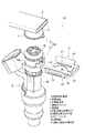
図1は本発明の第1の実施形態の燃料噴射装置1Aに用いられる燃料噴射弁3の斜視図、図2は燃料噴射装置1Aの要部の分解斜視図、図3は燃料噴射装置1Aの要部の断面図である。
【0025】
図1〜図3において、燃料噴射装置1Aは、図示しない燃料燃料タンク側に接続される金属製の燃料配管2と、図示しない内燃機関の吸気管側に固定される燃料噴射弁3と、燃料配管2及び燃料噴射弁3に嵌合される接続用クリップ4とを備えている。
【0026】
図1,図2に示すように、燃料配管2の下面側には金属製で円筒状の接続管5が固定され、この接続管5の内周面が後述する弁ケーシング10の接続部10aを嵌合により接続させる嵌合孔6になっている。また、接続管5の外周面の先端には抜け止め用フランジ部7が突設されている。この抜け止め用フランジ部7の一部には回転位置決め用突起8が更に突設されている。
【0027】
燃料噴射弁3の外殻をなす合成樹脂製の弁ケーシング10の一端側(燃料流入側)は円筒状の接続部10aとして形成されている。この弁ケーシング10の接続部10aの外周面には、環状の抜け止め用周溝11が形成されている。また、弁ケーシング10の接続部10aの外周面には位置決め用ブロック12が突設され、この位置決め用ブロック12には、軸方向で上方に開口する回転位置決め用凹部13が設けられている。この回転位置決め用凹部13の開口は、入口より奥に向かうに従って徐々に狭まるテーパ状に形成されている。また、回転位置決め用凹部13の奥位置の幅は、接続管5の回転位置決め用突起8の幅と同一若しくは若干だけ大きく設定されている。そして、これら回転位置決め用凹部13と回転位置決め用突起8とによって回転位置決め手段9Aが構成されている。
【0028】
図2,図3に示すように、接続用クリップ4は、弾性を有する金属材にて形成され、連結部15と、この連結部15の両端より延設された一対の弾性アーム部16,16を備えている。この一対の弾性アーム部16,16には矩形の抜け止め用溝孔17がそれぞれ形成されていると共に、一対の弾性アーム部16,16の内側には内面円弧状の抜け止め用嵌合片18がそれぞれ設けられている。
【0029】
次に、燃料配管2と燃料噴射弁3との接続作業の手順を説明する。
【0030】
図2に示すように、燃料配管2の接続管5の回転位置決め用突起8と燃料噴射弁3の弁ケーシング10の回転位置決め用凹部13の回転方向を位置合わせし、燃料配管2の接続管5の嵌合孔6内に燃料噴射弁3の弁ケーシング10の接続部10aを嵌合させて接続すると、燃料配管2の接続管5の回転位置決め用突起8が弁ケーシング10の回転位置決め用凹部13に係合される。この際、接続管5の嵌合孔6と弁ケーシング10の接続部10aはゴム製のOリング19によりシールされる。
【0031】
次に、接続用クリップ4の一対の抜け止め用嵌合片18,18の高さ位置を弁ケーシング10の抜け止め用周溝11の高さ位置に合わせ、接続用クリップ4を燃料配管2の接続管5及び燃料噴射弁3の弁ケーシング10の径方向より近接させると、接続用クリップ4の一対のアーム部16,16が弾性変形しつつ燃料配管2の接続管5及び燃料噴射弁3の弁ケーシング10の外周を徐々に挟み込むように近接される。
【0032】
そして、接続用クリップ4の連結部15の内面が弁ケーシング10の位置決め用ブロック12に接触する位置まで近接されると、一対のアーム部16,16の各抜け止め用溝孔17に接続管5の抜け止め用フランジ部7が嵌合し、且つ、一対のアーム部16,16の各抜け止め用嵌合片18が弁ケーシング10の抜け止め用周溝11に嵌合する。これにより、図3に示すように、燃料配管2と燃料噴射弁3との接続作業が完了する。
【0033】
燃料配管2の接続管5と燃料噴射弁3の弁ケーシング10間の軸方向の抜け移動は、接続用クリップ4の抜け止め用溝孔17と接続管5の抜け止め用フランジ部7との嵌合と、接続用クリップ4の抜け止め用嵌合片18と弁ケーシング10の抜け止め用周溝11との嵌合とによって阻止される。また、燃料配管2の接続管5と燃料噴射弁3の弁ケーシング10との回転方向の位置決めは、接続管5の回転位置決め用突起8と弁ケーシング10の回転位置決め用凹部13とによって行われる。
【0034】
上記構成によれば、燃料配管2の接続管5と燃料噴射弁3の弁ケーシング10とが接続用クリップ4を介することなく回転位置決めされるため、接続用クリップ4に位置決め機能を設ける必要がなく、また、燃料配管2の接続管5と燃料噴射弁3の弁ケーシング10とが1箇所で回転位置決めされる。従って、接続用クリップ4の構成を簡素化でき、接続用クリップ4を低コストにできると共に、回転位置決めに際してのばらつき要因が少なくなり、回転位置決めの公差を小さくできる。
【0035】
(第2の実施形態)
以下、本発明を具現化した第2の実施形態について図面を参照して説明する。
【0036】
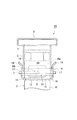
図4は本発明の第2の実施形態の燃料噴射装置1Bに用いられる燃料噴射弁3の斜視図、図5は燃料噴射装置1Bの要部の分解斜視図、図6は燃料噴射装置1Bの要部の断面図である。
【0037】
図4〜図6において、第2の実施形態の燃料噴射装置1Bは、前記第1の実施形態と同様に、燃料配管2と燃料噴射弁3と接続用クリップ4とを備え、前記第1実施形態のものと比較して回転位置決め用凹部20の構成のみが相違する。つまり、回転位置決め用凹部20は、軸方向ではなく円周方向に開口するように形成されている。この回転位置決め用凹部20の開口は、入口より奥に向かうに従って徐々に狭まるテーパ状に形成されている。そして、回転位置決め用凹部20の開口の奥位置の高さ寸法は、接続管5の回転位置決め用突起8の厚み(高さ寸法)と同一若しくは若干だけ大きく設定され、これら回転位置決め用凹部20と回転位置決め用突起8とによって回転位置決め手段9Bが構成されている。
【0038】
尚、他の構成は、前記第1の実施形態と同一であるため、前記第1の実施形態と同一構成部分には同一符号を付してその詳細な説明を省略する。
【0039】
この第2の実施形態では、燃料配管2の接続管5と燃料噴射弁3の弁ケーシング10の接続部10aとの接続作業に際して、弁ケーシング10の接続部10aを接続管5の嵌合孔6内に嵌合させて接続し、且つ、図4の矢印方向に燃料噴射弁3を回転することによって回転位置決め用突起8が回転位置決め用凹部20に係合される。従って、燃料配管2の接続管5と燃料噴射弁3の弁ケーシング10間の軸方向の抜け移動は、第1実施形態のように接続用クリップ4によって阻止されると共に、回転位置決め用突起8と回転位置決め用凹部20を形成する回転位置決め用ブロック12とによっても阻止される。
【0040】
上記構成によれば、燃料配管2の接続管5と燃料噴射弁3の弁ケーシング10とが接続用クリップ4を介することなく回転位置決めされると共に、接続用クリップ4を介することなく軸方向の抜け止めがなされる。従って、接続用クリップ4を基本的に使用しなくても燃料配管2の接続管5と燃料噴射弁3の弁ケーシング10の接続部10aとを接続できる。この第2実施形態のように接続用クリップ4を使用する場合には、抜け止め等が強化でき、燃料配管2の接続管5と燃料噴射弁3の弁ケーシング10の接続部10aとをより一層強固に接続できる。
【0041】
(第3の実施形態)
以下、本発明を具現化した第3の実施形態について図面を参照して説明する。
【0042】
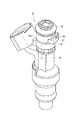
図7は本発明の第3の実施形態の燃料噴射装置1Cに用いられる燃料噴射弁3の斜視図、図8は燃料噴射装置1Cの要部の分解斜視図、図9は燃料噴射装置1Cの要部の断面図である。
【0043】
図7〜図9において、第3の実施形態の燃料噴射装置1Cは、前記第1の実施形態と同様に、燃料配管2と燃料噴射弁3と接続用クリップ4とを備え、前記第1の実施形態のものと比較して回転位置決め用凹部21の構成のみが相違する。つまり、回転位置決め用凹部21は、軸方向の上方側に開口するように形成されているが、その開口途中に一対の弾性突起22,22が相対向するように突設されている。また、回転位置決め用凹部21の一対の弾性突起22,22が突設されたエリアは、接続管5の回転位置決め用突起8の幅より狭く設定されているが、回転位置決め用凹部21の奥位置の幅は、接続管5の回転位置決め用突起8の幅と同一若しくは若干だけ大きく設定されている。そして、これら回転位置決め用凹部21と回転位置決め用突起8とによって回転位置決め手段9Cが構成されている。
【0044】
尚、他の構成は、前記第1の実施形態と同一であるため、前記第1の実施形態と同一構成部分には同一符号を付してその詳細な説明を省略する。
【0045】
この第3の実施形態では、燃料配管2の接続管5と燃料噴射弁3の弁ケーシング10の接続部10aとの接続作業に際して、弁ケーシング10の接続部10aを接続管5の嵌合孔6内に嵌合させて接続すると、接続管5の回転位置決め用突起8が一対の弾性突起22,22の各テーパ部に突き当たる。この突き当たり状態から更に嵌合すると、一対の弾性突起22,22が圧縮変形して回転位置決め用突起8の挿入が許容される。回転位置決め用突起8が一対の弾性突起22,22より奥位置まで挿入されると、一対の弾性突起22,22が弾性復帰変形し回転位置決め用突起8が回転位置決め用凹部21に係合される。従って、燃料配管2の接続管5と燃料噴射弁3の弁ケーシング10間の軸方向の抜け移動は、第1の実施形態のように接続用クリップ4によって阻止されると共に、回転位置決め用突起8と回転位置決め用凹部21の一対の弾性突起22,22によっても阻止される。
【0046】
上記構成によれば、燃料配管2の接続管5と燃料噴射弁3の弁ケーシング10とが接続用クリップ4を介することなく回転位置決めされると共に、接続用クリップ4を介することなく軸方向の抜け止めがなされる。従って、接続用クリップ4を基本的に使用しなくても燃料配管2の接続管5と燃料噴射弁3の弁ケーシング10の接続部10aとを接続できる。この第3の実施形態のように接続用クリップ4を使用する場合には、抜け止め等が強化でき、燃料配管2の接続管5と燃料噴射弁3の弁ケーシング10の接続部10aとをより一層強固に接続できる。
【0047】
尚、この発明は、次のような別の実施形態に具現化することができる。以下の別の実施形態において、上記各実施形態と同様な作用及び効果を得ることができる。
【0048】
(1)上記第1〜第3の実施形態において、接続管5に回転位置決め用突起8を、弁ケーシング10に回転位置決め用凹部13,20,21をそれぞれ設けるような構成とした。これに対し、接続管5に回転位置決め用凹部を、弁ケーシング10に回転位置決め用突起をそれぞれ設けるような構成にしても良い。このような構成とすることにより、同様な効果が得られる。
【0049】
(2)上記第2及び第3実施形態において、燃料噴射装置1B,1Cは、燃料配管2と燃料噴射弁3とを備え、接続用クリップ4を使用しないような構成とした。このような構成とすることにより、部品点数の削減となり、低コスト化、接続作業の簡素化等になる。
【0050】
さらに、上記各実施形態から把握し得る請求項以外の技術思想について、以下にその効果と共に記載する。
【0051】
(イ)請求項1に記載の燃料噴射装置1Aにおいて、接続管5に回転位置決め用突起8を、弁ケーシング10に回転位置決め用凹部13をそれぞれ設けることを特徴とする燃料噴射装置。
【0052】
この構成によれば、請求項1の発明と同様の作用・効果が得られる。
【0053】
(ロ)請求項1に記載の燃料噴射装置1Aにおいて、接続管5に回転位置決め用凹部を、弁ケーシング10に回転位置決め用突起をそれぞれ設けることを特徴とする燃料噴射装置。
【0054】
この構成によれば、請求項1の発明と同様の作用・効果が得られる。
【0055】
(ハ)請求項2に記載の燃料噴射装置1Bにおいて、接続管5に回転位置決め用突起8を、弁ケーシング10に回転位置決め用凹部20をそれぞれ設けることを特徴とする燃料噴射装置。
【0056】
この構成によれば、請求項2の発明と同様の作用・効果が得られる。
【0057】
(ニ)請求項2に記載の燃料噴射装置1Bにおいて、接続管5に回転位置決め用凹部を、弁ケーシング10に回転位置決め用突起をそれぞれ設けることを特徴とする燃料噴射装置。
【0058】
この構成によれば、請求項2の発明と同様の作用・効果が得られる。
【0059】
(ホ)(ハ)、(ニ)に記載の燃料噴射装置1Bにおいて、接続管5と弁ケーシング10との間の軸方向の抜け移動を阻止する接続用クリップ4を備えたことを特徴とする燃料噴射装置。
【0060】
この構成によれば、接続管5と弁ケーシング10との間の抜け止め等を強化でき、接続管5と弁ケーシング10をより一層強固に接続できる。
【0061】
(ヘ)請求項3に記載の燃料噴射装置1Cにおいて、接続管5に回転位置決め用突起8を、弁ケーシング10に回転位置決め用凹部21をそれぞれ設けることを特徴とする燃料噴射装置。
【0062】
この構成によれば、請求項3の発明と同様の作用・効果が得られる。
【0063】
(ト)請求項3に記載の燃料噴射装置1Cにおいて、接続管5に回転位置決め用凹部を、弁ケーシング10に回転位置決め用突起をそれぞれ設けることを特徴とする燃料噴射装置。
【0064】
この構成によれば、請求項3の発明と同様の作用・効果が得られる。
【0065】
(チ)(ヘ)、(ト)に記載の燃料噴射装置1Cにおいて、接続管5と弁ケーシング10との間の軸方向の抜け移動を阻止する接続用クリップ4を備えたことを特徴とする燃料噴射装置。
【0066】
この構成によれば、接続管5と弁ケーシング10との間の抜け止め等を強化でき、接続管5と弁ケーシング10をより一層強固に接続できる。
【図面の簡単な説明】
【図1】本発明の第1の実施形態を示し、燃料噴射装置に用いられる燃料噴射弁の斜視図である。
【図2】本発明の第1の実施形態を示し、燃料噴射装置の要部の分解斜視図である。
【図3】本発明の第1の実施形態を示し、燃料噴射装置の要部の断面図である。
【図4】本発明の第2の実施形態を示し、燃料噴射装置に用いられる燃料噴射弁の斜視図である。
【図5】本発明の第2の実施形態を示し、燃料噴射装置の要部の分解斜視図である。
【図6】本発明の第2の実施形態を示し、燃料噴射装置の要部の断面図である。
【図7】本発明の第3の実施形態を示し、燃料噴射装置に用いられる燃料噴射弁の斜視図である。
【図8】本発明の第3の実施形態を示し、燃料噴射装置の要部の分解斜視図である。
【図9】本発明の第3の実施形態を示し、燃料噴射装置の要部の断面図である。
【図10】従来例を示し、燃料配管の接続管と燃料噴射弁との接続箇所を一部切欠きにて示す側面図である。
【図11】従来例を示し、図10の矢印Aの方向で見た図である。
【図12】従来例の接続用クリップの正面図である。
【図13】従来例の接続用クリップの側面図である。
【図14】従来例の接続用クリップの平面図である。
【符号の説明】
1A,1B,1C 燃料噴射装置
2 燃料配管
3 燃料噴射弁
4 接続用クリップ
5 接続管
6 嵌合孔
8 回転位置決め用突起
9A,9B,9C 回転位置決め手段
10 弁ケーシング
10a 接続部
13,20,21 回転位置決め用凹部
22 弾性突起[0001]
TECHNICAL FIELD OF THE INVENTION
The present invention relates to a fuel injection device that supplies fuel in a fuel tank to a fuel injection valve via a fuel pipe and injects fuel from the fuel injection valve to the intake side of the internal combustion engine. Related to connection structure.
[0002]
[Prior art]
Conventionally, various technologies relating to a connection structure between a fuel pipe and a fuel injection valve have been proposed. Japanese Patent Publication No. 4-500259 discloses a fuel injection device as an example.
[0003]
As shown in FIGS. 10 and 11, the
[0004]
A
[0005]
One end side (fuel inflow side) of the
[0006]
As shown in FIGS. 12 to 14, the
[0007]
Next, a procedure for connecting the
[0008]
The connecting
[0009]
Next, the
[0010]
When the inner surface of the connecting
[0011]
The axial displacement between the connecting
[0012]
The positioning of the
[0013]
[Patent Document 1]
Japanese Patent Publication No. 4-500259
[Problems to be solved by the invention]
However, in the conventional
[0015]
Further, the
[0016]
The present invention has been made in view of the above-described circumstances, and an object of the present invention is to provide a fuel injection device that can reduce the cost of a connection clip and reduce the tolerance of rotational positioning.
[0017]
[Means for Solving the Problems]
In order to achieve the above object, according to the first aspect of the present invention, a connection pipe is provided in a fuel pipe, a connection portion is provided at an end of the valve casing of the fuel injection valve on a fuel inflow side, and the connection of the valve casing is performed. Part is connected to the connection pipe in the axial direction as a connection direction, and a connection clip is fitted to the connection part of the valve casing and the connection pipe, and the connection clip connects the valve casing to the connection pipe. In a fuel injection device configured to connect the fuel pipe and the fuel injection valve by preventing the axial displacement between the fuel pipe and the fuel injection valve, a rotation positioning protrusion is provided on one of the connection pipe and the valve casing. On the other side, there is provided a rotation positioning recess that opens in the axial direction, and by connecting a connection portion of the valve casing to the connection pipe, the rotation positioning projection engages with the rotation positioning recess. And purpose in that a rotational positioning means for the mutual rotary direction positioning is performed.
[0018]
According to the above configuration, since the connection pipe of the fuel pipe and the valve casing of the fuel injection valve are rotationally positioned without the interposition of the connection clip, there is no need to provide a positioning function to the connection clip. The connection pipe and the valve casing of the fuel injection valve are rotationally positioned at one place. Accordingly, the configuration of the connection clip can be simplified, the cost of the connection clip can be reduced, and a variation factor at the time of rotational positioning is reduced, and the tolerance of rotational positioning can be reduced.
[0019]
According to a second aspect of the present invention, a connecting pipe is provided in the fuel pipe, a connecting portion is provided at an end of the valve casing of the fuel injection valve on the fuel inflow side, and the connecting portion of the valve casing is axially connected to the connecting pipe. In the fuel injection device configured to be connected as a connection direction, one of the connection pipe and the valve casing is provided with a rotation positioning projection, and the other is provided with a rotation positioning concave portion that opens in a circumferential direction, The connection portion of the casing is connected to the inside of the connection pipe, and by rotating, the rotation positioning projection engages with the rotation positioning concave portion, thereby performing the mutual positioning in the rotation direction and the axial removal movement. The rotation positioning means for preventing the rotation is provided.
[0020]
According to the above configuration, the connection pipe of the fuel pipe and the valve casing of the fuel injection valve are rotationally positioned without interposition of the connection clip, and are prevented from coming off in the axial direction without interposition of the connection clip. Therefore, the connecting pipe of the fuel pipe and the connecting portion of the valve casing of the fuel injection valve can be connected without basically using the connecting clip. In the case of using the connection clip, the stopper and the like can be strengthened, and the connection pipe of the fuel pipe and the connection portion of the valve casing of the fuel injection valve can be more firmly connected.
[0021]
Further, in the invention according to
[0022]
According to the above configuration, the connection pipe of the fuel pipe and the valve casing of the fuel injection valve are rotationally positioned without interposition of the connection clip, and are prevented from coming off in the axial direction without interposition of the connection clip. Therefore, the connecting pipe of the fuel pipe and the connecting portion of the valve casing of the fuel injection valve can be connected without basically using the connecting clip. In the case of using the connection clip, the stopper and the like can be strengthened, and the connection pipe of the fuel pipe and the connection portion of the valve casing of the fuel injection valve can be more firmly connected.
[0023]
BEST MODE FOR CARRYING OUT THE INVENTION
(1st Embodiment)
Hereinafter, a first embodiment of the present invention will be described with reference to the drawings.
[0024]
FIG. 1 is a perspective view of a
[0025]
1 to 3, a
[0026]
As shown in FIGS. 1 and 2, a
[0027]
One end side (fuel inflow side) of a synthetic
[0028]
As shown in FIGS. 2 and 3, the
[0029]
Next, a procedure for connecting the
[0030]
As shown in FIG. 2, the rotation direction of the
[0031]
Next, the height of the pair of retaining
[0032]
When the inner surface of the connecting
[0033]
The axial displacement between the
[0034]
According to the above configuration, since the
[0035]
(Second embodiment)
Hereinafter, a second embodiment of the present invention will be described with reference to the drawings.
[0036]
FIG. 4 is a perspective view of a
[0037]
4 to 6, the
[0038]
Since other configurations are the same as those of the first embodiment, the same components as those of the first embodiment are denoted by the same reference numerals, and detailed description thereof will be omitted.
[0039]
In the second embodiment, when connecting the connecting
[0040]
According to the above configuration, the
[0041]
(Third embodiment)
Hereinafter, a third embodiment of the present invention will be described with reference to the drawings.
[0042]
FIG. 7 is a perspective view of a
[0043]
7 to 9, a
[0044]
Since other configurations are the same as those of the first embodiment, the same components as those of the first embodiment are denoted by the same reference numerals, and detailed description thereof will be omitted.
[0045]
In the third embodiment, when connecting the connecting
[0046]
According to the above configuration, the
[0047]
Note that the present invention can be embodied in another embodiment as follows. In another embodiment described below, the same operation and effect as those of the above embodiments can be obtained.
[0048]
(1) In the first to third embodiments, the
[0049]
(2) In the second and third embodiments, the
[0050]
Furthermore, technical ideas other than the claims that can be grasped from the above embodiments will be described below together with their effects.
[0051]
(A) The fuel injection device according to claim 1, wherein the connection pipe (5) is provided with a rotation positioning projection (8) and the valve casing (10) is provided with a rotation positioning recess (13).
[0052]
According to this configuration, the same operation and effect as the first aspect can be obtained.
[0053]
(B) The fuel injection device according to claim 1, wherein the connection pipe (5) is provided with a rotation positioning recess and the valve casing (10) is provided with a rotation positioning projection.
[0054]
According to this configuration, the same operation and effect as the first aspect can be obtained.
[0055]
(C) The fuel injection device according to
[0056]
According to this configuration, the same operation and effect as those of the second aspect can be obtained.
[0057]
(D) The fuel injection device according to
[0058]
According to this configuration, the same operation and effect as those of the second aspect can be obtained.
[0059]
(E) The
[0060]
According to this configuration, the stopper between the
[0061]
(F) The fuel injection device according to
[0062]
According to this configuration, the same operation and effect as the third aspect of the invention can be obtained.
[0063]
(G) The fuel injection device according to
[0064]
According to this configuration, the same operation and effect as the third aspect of the invention can be obtained.
[0065]
(H) The
[0066]
According to this configuration, the stopper between the
[Brief description of the drawings]
FIG. 1 shows a first embodiment of the present invention, and is a perspective view of a fuel injection valve used in a fuel injection device.
FIG. 2 shows the first embodiment of the present invention, and is an exploded perspective view of a main part of the fuel injection device.
FIG. 3 shows the first embodiment of the present invention and is a cross-sectional view of a main part of the fuel injection device.
FIG. 4 shows a second embodiment of the present invention, and is a perspective view of a fuel injection valve used in a fuel injection device.
FIG. 5 shows the second embodiment of the present invention and is an exploded perspective view of a main part of a fuel injection device.
FIG. 6 shows a second embodiment of the present invention and is a cross-sectional view of a main part of a fuel injection device.
FIG. 7 shows a third embodiment of the present invention and is a perspective view of a fuel injection valve used in a fuel injection device.
FIG. 8 shows a third embodiment of the present invention, and is an exploded perspective view of a main part of a fuel injection device.
FIG. 9 shows a third embodiment of the present invention and is a cross-sectional view of a main part of a fuel injection device.
FIG. 10 is a side view showing a conventional example, in which a connection portion between a connection pipe of a fuel pipe and a fuel injection valve is partially cut away.
11 shows a conventional example and is a view seen in the direction of arrow A in FIG.
FIG. 12 is a front view of a conventional connection clip.
FIG. 13 is a side view of a conventional connection clip.
FIG. 14 is a plan view of a conventional connection clip.
[Explanation of symbols]
1A, 1B, 1C
Claims (3)
前記接続管と前記弁ケーシングとのいずれか一方に回転位置決め用突起を、他方に軸方向に開口する回転位置決め用凹部を設け、前記弁ケーシングの接続部を前記接続管内に接続することによって前記回転位置決め用突起が前記回転位置決め用凹部に係合し、互いの回転方向の位置決めがなされる回転位置決め手段を設けたことを特徴とする燃料噴射装置。A connection pipe is provided in the fuel pipe, a connection section is provided at an end of the fuel injection valve on the fuel inflow side of a valve casing, and the connection section of the valve casing is connected to the connection pipe in an axial direction as a connection direction, and A connection clip is fitted to a connection portion of the valve casing and the connection pipe, and the connection clip prevents axial displacement between the valve casing and the connection pipe, thereby preventing the fuel pipe from being connected to the fuel injection pipe. In a fuel injection device that is connected to a valve,
A rotation positioning projection is provided on one of the connection pipe and the valve casing, and a rotation positioning concave part which is opened in the axial direction is provided on the other of the connection pipe and the valve casing. A fuel injection device comprising a rotation positioning means for engaging a positioning projection with the rotation positioning recess and performing positioning in the rotation direction with respect to each other.
前記接続管と前記弁ケーシングとのいずれか一方に回転位置決め用突起を、他方に周方向に開口する回転位置決め用凹部を設け、前記弁ケーシングの接続部を前記接続管内に接続し、且つ、回転することによって前記回転位置決め用突起が前記回転位置決め用凹部に係合し、互いの回転方向の位置決めがなされると共に軸方向の抜け移動が阻止される回転位置決め手段を設けたことを特徴とする燃料噴射装置。A connection pipe is provided in a fuel pipe, a connection section is provided at an end of the fuel injection valve on a fuel inflow side of a valve casing, and the connection section of the valve casing is connected to the connection pipe in an axial direction as a connection direction. In the injection device,
A rotation positioning projection is provided on one of the connection pipe and the valve casing, and a rotation positioning recess is provided on the other of the connection pipe and the valve casing. The connection portion of the valve casing is connected to the inside of the connection pipe. The rotation positioning projections engage with the rotation positioning recesses, thereby providing rotation positioning means for positioning each other in the rotation direction and preventing axial displacement. Injection device.
前記接続管と前記弁ケーシングとのいずれか一方に回転位置決め用突起を、他方に開口途中に弾性突起が突設された回転位置決め用凹部を設け、前記弁ケーシングの接続部を前記接続管内に前記弾性突起を弾性変形させて嵌合することによって前記回転位置決め用突起が前記回転位置決め用凹部に係合し、互いの回転方向の位置決めがなされると共に軸方向の抜け移動が阻止される回転位置決め手段を設けたことを特徴とする燃料噴射装置。A connection pipe is provided in a fuel pipe, a connection section is provided at an end of the fuel injection valve on a fuel inflow side of a valve casing, and the connection section of the valve casing is connected to the connection pipe in an axial direction as a connection direction. In the injection device,
A rotation positioning projection is provided on one of the connection pipe and the valve casing, and a rotation positioning recess provided with an elastic projection protruding in the middle of the opening is provided on the other, and a connection portion of the valve casing is provided in the connection pipe. Rotational positioning means for engaging the rotation positioning projections with the rotation positioning recesses by elastically deforming and fitting the elastic projections, thereby positioning each other in the rotation direction and preventing the axial displacement movement. A fuel injection device comprising:
Priority Applications (2)
| Application Number | Priority Date | Filing Date | Title |
|---|---|---|---|
| JP2003135914A JP2004339992A (en) | 2003-05-14 | 2003-05-14 | Fuel injector |
| CNA2004100432463A CN1550660A (en) | 2003-05-14 | 2004-05-14 | Fuel injection device |
Applications Claiming Priority (1)
| Application Number | Priority Date | Filing Date | Title |
|---|---|---|---|
| JP2003135914A JP2004339992A (en) | 2003-05-14 | 2003-05-14 | Fuel injector |
Publications (1)
| Publication Number | Publication Date |
|---|---|
| JP2004339992A true JP2004339992A (en) | 2004-12-02 |
Family
ID=33526039
Family Applications (1)
| Application Number | Title | Priority Date | Filing Date |
|---|---|---|---|
| JP2003135914A Pending JP2004339992A (en) | 2003-05-14 | 2003-05-14 | Fuel injector |
Country Status (2)
| Country | Link |
|---|---|
| JP (1) | JP2004339992A (en) |
| CN (1) | CN1550660A (en) |
Cited By (8)
| Publication number | Priority date | Publication date | Assignee | Title |
|---|---|---|---|---|
| KR100692730B1 (en) | 2005-08-17 | 2007-03-09 | 현대자동차주식회사 | Fixing device for engine injector |
| JP2010255483A (en) * | 2009-04-23 | 2010-11-11 | Ihi Corp | Turbocharger |
| JP2010275940A (en) * | 2009-05-29 | 2010-12-09 | Keihin Corp | Fuel injection valve mounting structure |
| JP2011032867A (en) * | 2009-07-29 | 2011-02-17 | Honda Motor Co Ltd | Fuel supply device for multi-cylinder internal combustion engine |
| JP2016011646A (en) * | 2014-06-30 | 2016-01-21 | ダイハツ工業株式会社 | Method for assembling fuel supply system and clip |
| JP2016011647A (en) * | 2014-06-30 | 2016-01-21 | ダイハツ工業株式会社 | Assembling method of fuel supply device and jig used for the same |
| JP2016079836A (en) * | 2014-10-14 | 2016-05-16 | ダイハツ工業株式会社 | Injector unit of internal combustion engine |
| DE102014211136B4 (en) | 2013-06-18 | 2023-09-21 | Suzuki Motor Corporation | Fuel supply line with injector connection |
Families Citing this family (1)
| Publication number | Priority date | Publication date | Assignee | Title |
|---|---|---|---|---|
| DE102009028473A1 (en) * | 2009-08-12 | 2011-02-17 | Robert Bosch Gmbh | connector |
-
2003
- 2003-05-14 JP JP2003135914A patent/JP2004339992A/en active Pending
-
2004
- 2004-05-14 CN CNA2004100432463A patent/CN1550660A/en active Pending
Cited By (9)
| Publication number | Priority date | Publication date | Assignee | Title |
|---|---|---|---|---|
| KR100692730B1 (en) | 2005-08-17 | 2007-03-09 | 현대자동차주식회사 | Fixing device for engine injector |
| JP2010255483A (en) * | 2009-04-23 | 2010-11-11 | Ihi Corp | Turbocharger |
| JP2010275940A (en) * | 2009-05-29 | 2010-12-09 | Keihin Corp | Fuel injection valve mounting structure |
| US8826890B2 (en) | 2009-05-29 | 2014-09-09 | Keihin Corporation | Fuel injection valve mounting structure |
| JP2011032867A (en) * | 2009-07-29 | 2011-02-17 | Honda Motor Co Ltd | Fuel supply device for multi-cylinder internal combustion engine |
| DE102014211136B4 (en) | 2013-06-18 | 2023-09-21 | Suzuki Motor Corporation | Fuel supply line with injector connection |
| JP2016011646A (en) * | 2014-06-30 | 2016-01-21 | ダイハツ工業株式会社 | Method for assembling fuel supply system and clip |
| JP2016011647A (en) * | 2014-06-30 | 2016-01-21 | ダイハツ工業株式会社 | Assembling method of fuel supply device and jig used for the same |
| JP2016079836A (en) * | 2014-10-14 | 2016-05-16 | ダイハツ工業株式会社 | Injector unit of internal combustion engine |
Also Published As
| Publication number | Publication date |
|---|---|
| CN1550660A (en) | 2004-12-01 |
Similar Documents
| Publication | Publication Date | Title |
|---|---|---|
| JP4228922B2 (en) | Quick connector | |
| US6612622B2 (en) | Rotatable quick connector | |
| US5520151A (en) | Fuel injection device | |
| JP5570320B2 (en) | Fuel tank piping structure | |
| EP1113210B1 (en) | Quick connector with swivelable retainer housing | |
| JP3383168B2 (en) | Fuel tank check valve | |
| US20070132235A1 (en) | Fluid quick connector with integral pivotal retainer | |
| JP2004339992A (en) | Fuel injector | |
| JP4040109B2 (en) | Equipment used for fuel units | |
| US4982983A (en) | Perfected injector supply fitting | |
| JP2004132233A (en) | Air intake device for internal combustion engine | |
| JP4862778B2 (en) | Fuel damper fixing clip | |
| JP4405111B2 (en) | Fuel injector holding device | |
| JP5687032B2 (en) | Seal structure of passage forming member coupling part | |
| JPH04296291A (en) | Pipe joint | |
| JP2001304207A (en) | Fastening structure | |
| JP5687872B2 (en) | Valve mounting structure | |
| JP3669222B2 (en) | Quick connector | |
| JP3993610B2 (en) | Fuel injection valve | |
| JP4088125B2 (en) | connector | |
| JP2016507031A (en) | Fuel line connector assembly | |
| JP4220211B2 (en) | Piping connector | |
| JP2602675Y2 (en) | Captive fittings | |
| JP3700851B2 (en) | Half-mating prevention clip for connectors | |
| JP4703885B2 (en) | connector |
Legal Events
| Date | Code | Title | Description |
|---|---|---|---|
| A711 | Notification of change in applicant |
Free format text: JAPANESE INTERMEDIATE CODE: A712 Effective date: 20041217 |
|
| A621 | Written request for application examination |
Effective date: 20060316 Free format text: JAPANESE INTERMEDIATE CODE: A621 |
|
| A131 | Notification of reasons for refusal |
Free format text: JAPANESE INTERMEDIATE CODE: A131 Effective date: 20070619 |
|
| A02 | Decision of refusal |
Free format text: JAPANESE INTERMEDIATE CODE: A02 Effective date: 20071016 |