JP2004339976A - Piston ring tension regulator - Google Patents
Piston ring tension regulator Download PDFInfo
- Publication number
- JP2004339976A JP2004339976A JP2003135579A JP2003135579A JP2004339976A JP 2004339976 A JP2004339976 A JP 2004339976A JP 2003135579 A JP2003135579 A JP 2003135579A JP 2003135579 A JP2003135579 A JP 2003135579A JP 2004339976 A JP2004339976 A JP 2004339976A
- Authority
- JP
- Japan
- Prior art keywords
- oil
- piston
- ring
- tension
- oil passage
- Prior art date
- Legal status (The legal status is an assumption and is not a legal conclusion. Google has not performed a legal analysis and makes no representation as to the accuracy of the status listed.)
- Withdrawn
Links
Images


Abstract
Description
【0001】
【発明の属する技術分野】
本発明は、内燃機関のシリンダとシリンダ内を往復するピストンの外周との間隙に設けられるピストンリングの張力を可変調整する装置に関する。
【0002】
【従来の技術】
周知のように、内燃機関(以下、エンジンという)のシリンダと、シリンダ内を往復するピストンの外周との間隙には、複数のピストンリングが設けられる。ピストンリングは、ピストンの外周に形成される周溝に装着される。
【0003】
例えば、ピストンリングの一種であるオイルリングは、シリンダ及びピストン間に存在する潤滑オイルをかき落とす役割を担う。
【0004】
オイルリングがシリンダ及びピストン間に存在する潤滑オイルをかき落とす効率は、オイルリングがシリンダの内周面を押す力(ピストンリングの張力)の大きさによって決定づけられる場合が多い。
【0005】
ここで、エンジンの良好な運転状態を保持するためには、エンジンの回転数が高くなるほど多量の潤滑オイルをシリンダ及びピストン間に供給する必要がある。そして、シリンダ及びピストン間に供給される潤滑オイルの量が大きくなるほど、より効率的に潤滑オイルをかき落とす能力がオイルリングに求められる。
【0006】
例えば特許文献1には、クランクシャフト及びコンロッド内に形成されたオイル通路を通じて作動オイルをピストン内に導き、この作動オイルの圧力によってオイルリングの張力を調整する技術が記載されている。また、特許文献2には、ピストンリングを磁性体によって形成するとともに、通電によって電磁力を発生するステータコイルをシリンダ内壁に埋め込み、ステータコイルに対する通電制御を行うことにより、ピストンリングの張力を調整する技術が記載されている。
【0007】
【特許文献1】
特開平6−123357号公報
【特許文献2】
特開2001−200752号公報
【発明が解決しようとする課題】
しかし、特許文献1に記載された技術では、作動オイル(オイル圧)を伝達する経路が長すぎて、エンジンの運転状態に対応するピストンの張力を得る上で、十分な応答性を確保することが困難である。また、特許文献2に記載された技術によれば、十分な応答性を確保することはできるが、複雑なハードウエア構造及びソフトウエア構造が必要になるため、適用対象となる装置の製造コストが高騰する。
【0008】
本発明は、このような実情に鑑みてなされたものであって、その目的とするところは、エンジンのシリンダ内を往復動するピストンの外周に設けられるオイルリングの張力を当該機関の運転状態に応じて適切に調整することができる簡易な構成の装置を提供することにある。
【0009】
【課題を解決するための手段】
上記目的を達成するために、本発明は、
(1)内燃機関のシリンダ内を往復動するピストンの外周溝に装着されるピストンリングの張力を調整する装置であって、前記ピストンの内部に形成されるオイル通路と、該オイル通路に供給されるオイルの圧力に基づいて、前記ピストンの内部から前記ピストンの外周に向かって前記ピストンリングを押す押力付与手段と、圧送されるオイルを噴出させ前記オイル通路に導入する噴出機構と、を備えることを要旨とする。
【0010】
同構成によれば、当該機関の運転状態に応じたピストンリングの張力調整を、簡易な構成を用いて正確に行える。
【0011】
(2)なお、前記内燃機関の回転と機械的に連動して前記噴出機構にオイルを圧送するポンプを備えるのが好ましい。
【0012】
同構成によれば、ピストンリングの張力調整を、当該機関のエンジン回転数に応じて正確に行える。
【0013】
(3)また、前記ピストンの内部に形成されるオイル通路は、前記ピストンの周方向に沿って形成される環状オイル通路であるのが好ましい。
【0014】
同構成によれば、例えばピストンの冷却用に設けられる既存のオイル通路を流用してピストンリングの張力を調整するためのオイル圧を供給することができる。従って、製造工程を一層簡易にし、製造コストを一層低減することことができる。
【0015】
【発明の実施の形態】
(第1の実施の形態)
以下、本発明を具体化した第1の実施の形態について説明する。
【0016】
〔ピストンリング張力調整装置の構造〕
図1は、本実施の形態のピストンリング張力調整装置について、その主要構造を示す概略図である。
【0017】
同図1において、内燃機関(以下、単にエンジンという)100は、燃焼室1内において燃料及び空気の混合気を燃焼させる。このとき発生する燃焼エネルギーにより、コンロッド2の一端に連結されたピストン3をシリンダ4内で往復動させ、コンロッド2の他端に連結されたクランクシャフト(図示略)を回転させる。
【0018】
ピストン3の外周には、3つの周溝が形成されている。各周溝3a,3b,3cには、ピストンリング5a,5b,5cが装着されている。ピストン3の頭頂2d(燃焼室1)に最も近いピストンリング(第1コンプレッションリング)4aは、主に、燃焼室1からクランクケース(クランクシャフトの収容空間)7に漏出するブローバイガスの量を抑制する機能を有する。クランクケース7に最も近いピストンリング(オイルリング)5cは、主に、ピストン3及びシリンダ4の間隙(摺動部位)に供給されるオイル(潤滑オイル)をかき落とす機能を有する。第1コンプレッションリング5a及びオイルリング5cの中間に配置される第2コンプレッションリング5bは、両リング5a,5cの機能(ブローバイガス量の抑制及びオイルのかき落とし)を併せ持つ。
【0019】
本実施の形態のピストンリング張力調整装置10は、ピストン3の内部から外周(シリンダ4の内壁)に向かってオイルリング5cを押し、さらにその押力(オイルリング5cの張力)の大きさをエンジン100の運転状態に応じて調整する機能を有する。ピストンリング張力調整装置10は、ピストン3の内部に形成される環状オイル通路11、環状オイル通路11に供給されるオイルの圧力に基づいてピストン3の内部からピストン3の外周に向かってオイルリング5cを押す押力付与機構20、オイルポンプ(図示略)から圧送されるオイルを噴出させ環状オイル通路11に導入する噴出機構30等を主な構成要素として含む。なお、環状オイル通路11に供給されるオイルは、押力付与機構20を機能させる他、ピストン3を冷却する役割を有する。
【0020】
噴出機構30は、蓄圧オイル通路31、噴出管32、チェック弁33等を備える。蓄圧オイル通路31は、エンジン100のシリンダブロック6内に形成され、オイルポンプから圧送されるオイルを移送する。噴出管32は、クランクケース7内に配置され、シリンダ4内のピストン3に臨むオイルの噴出口32aを有する。チェック弁33は、蓄圧オイル通路31及び噴出管32間の連通部位Cに設けられ、蓄圧オイル通路31内のオイル圧が所定値を上回った場合にのみ開弁する。なお、蓄圧オイル通路31には、周知のリリーフ弁(図示略)が設けられている。リリーフ弁は、蓄圧オイル通路31内のオイル圧が予め設定される上限値(リリーフ圧)を上回ると開弁し同通路31内のオイルを外部に逃がす。リリーフ弁の機能により、同通路31内のオイル圧がリリーフ圧を大幅に上回ることはない。
【0021】
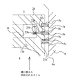
図2は、押力付与機構20の近傍を示す拡大図である。押力付与機構20は、リング支持部材21c、ロッド22c、コイルバネ24c、受圧板23c、スプリングハウジング25c等を備える。ロッド22cは、周溝3cの底部から環状オイル通路11に亘りピストン3内に貫通形成される孔8c内において往復動可能に支持される。ロッド22の一端(周溝3cに突出する部分の先端)にはリング支持部材21cが固定される。リング支持部材21cは、周溝3cの底部においてオイルリング5cを支持する。ロッド22cの他端(環状オイル通路11に突出する部分の先端)には受圧板23cが固定される。また、ロッド22cのうち環状オイル通路11に突出する部分の外周にはコイルバネ24cが取り付けられ、ピストン3の外周から環状オイル通路11に向かって受圧板23cを付勢する。環状オイル通路11の内壁には、ロッド22cの一部(環状オイル通路11に突出する部分)、受圧板23c及びコイルバネ24cを収容するようにシリンダ4が取り付けられる。環状オイル通路11内のオイル圧が高くなると、ハウジング25cの開口端から受圧板23cにオイル圧が作用し、コイルバネ24cの付勢力にうち勝ってピストン3の内部からシリンダ内壁6aに向かってロッド22を押す。これにより、オイルリング5cがシリンダ内壁6aに向かって押しつけられる(オイルリング5cの張力が高くなる)。
【0022】
なお、押力付与機構20は、1つでも機能するが、ピストン3の周溝に沿って複数設けられるのが好ましい。
【0023】
環状オイル通路11には、オイルの導入通路11aと排出口(図示略)とが設けられている。噴出管32から噴出するオイルが導入通路11aから環状オイル通路11に導入されるように、導入通路11a及び噴出管32の噴出口32aの配置は設定されている。
【0024】
〔ピストンリング張力調整装置の機能〕
次に、このような構成を有するピストンリング張力調整装置10の機能について説明する。本実施の形態のピストンリング張力調整装置10では、エンジン100の回転速度(エンジン回転数)NEに応じてオイルポンプのポンプ機能の大きさ(蓄圧オイル通路31内のオイル圧)が変化する。この蓄圧オイル通路31内のオイル圧が変化することにより、噴出管32の噴出口32aから噴出するオイルの流量、ひいては環状オイル通路11内のオイル圧が変化する。そして、環状オイル通路11内のオイル圧に応じて押力付与機構20がオイルリング5cをシリンダ内壁6aに押しつける。すなわち、エンジン回転数NEに応じてオイルリング5cの張力が高められる。
【0025】
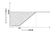
図3には、エンジン回転数NEとオイルリング5cの張力との関係を示す。同図3において実線で示すように、エンジン回転数NEが所定値NE1以下である場合、蓄圧オイル通路31内のオイル圧が低いためにチェック弁33が開かず、噴出管32から環状オイル通路11にオイルが供給されないため、オイルリング5cの張力は極めて低い数値となる(押力付与機構20の作用に基づく張力の増大分は、「0」となる)。エンジン回転数NEが所定値を上回ると噴出管32から環状オイル通路11にオイルが供給され、エンジン回転数NEの上昇に伴い環状オイル通路11内のオイル圧も上昇する。そして、環状オイル通路11内のオイル圧の上昇に伴いオイルリング5cの張力が高くなる。
【0026】
なお、従来技術において説明したように、エンジン回転数NEが高くなるほどオイルリング5cに求められる能力(ピストン3及びシリンダ4間の潤滑オイルをかき落とす能力)は大きくなる。このため、同図3中において一点鎖線で示すように、オイルリング5cの張力を可変とする機能を持たない従来のエンジンでは、オイルリング5cの張力を、エンジン回転数NEの最大値NEMAXに対応する値に(強めに)設定しておく必要がある。一方、オイルリング5cの張力が高くなるほど、オイルリング5c及びシリンダ4間の摩擦も増大する。このため、オイルリング5cの張力を強めに設定すると、エンジン回転数NEが低い条件下でエンジンの運転に伴う機械損失が増大することになっていた。
【0027】
この点、本実施の形態によれば、オイルポンプから圧送されるオイルの圧力を利用することにより、オイルリング5cの張力調整をエンジン回転数NEに応じて正確に行うことができる。
【0028】
また、オイルの圧力をオイルリング5cの張力に変換するために簡易な構成(押力付与機構20)を用いているため、製造工程も煩雑にならない。
【0029】
また、押力付与機構20を作動させるためのオイル圧を伝達するオイル通路が短く、その構造も複雑でない。このため、エンジン回転数NEの変化に対するオイルリング5cの張力変化の応答性も高い。
【0030】
とくに、本実施の形態においては、ピストンリング張力調整装置10の一部として、本来ピストン3を冷却するためにピストン3内に形成される環状オイル通路11と、環状オイル通路11に冷却用オイルを供給するためのオイル通路構造を流用している。この点においても、製造工程が煩雑とならず、製造コストも安価になる。
【0031】
しかも、エンジン回転数NEに応じてその循環効率(流量)が高まるピストン3の冷却用オイルの圧力を、オイルリング5cの張力調整に用いることにより、エンジン回転数NEに対応する適切な張力調整が行われる。
【0032】
さらに、オイルリング5cの張力を調整するアクチュエータ(押力付与機構20に相当)を駆動するために緻密な通電制御が必要になることもない。
【0033】
またとくに、いわゆるアイドルストップを実施する内燃機関や、モータ及び内燃機関の協働によって車両等の駆動力を得るハイブリッドエンジンのように、内燃機関の始動及び停止を頻繁に繰り返すエンジンシステムでは、モータによる内燃機関の再始動を頻繁に行う。このようなエンジンシステムに本実施の形態のオイルリング張力調整装置10を採用すれば、内燃機関の始動時(エンジン回転数が低い条件下)におけるオイルリングの張力(シリンダ内壁に対するオイルリングの静摩擦係数及び動摩擦係数)を極めて小さな値に設定することができる。この結果、内燃機関の燃費効率を向上することができる。また、内燃機関の始動に用いられるモータを小型化することも可能になる。
【0034】
(第2の実施の形態)
以下、本発明を具体化した第2の実施の形態について、第1の実施の形態と異なる点を中心に説明する。なお、第2の実施の形態の構成部材のうち、第1の実施の形態のものと同等の構造及び機能を有するものは、同一の符号を用い、ここでの重複する説明は省略する。
図4は、本実施の形態のピストンリング張力調整装置の一部である押力付与機構近傍を示す拡大図である。同図4に示すように、本実施の形態のピストンリング張力調整装置は、リング支持部材21b、ロッド22b、受圧板23b、コイルバネ24b、スプリングハウジング25b等からなる押力付与機構(第1の実施の形態にかかる押力付与機構20と略同一の構造を有するもの)を、第2コンプレッションリング5bの張力を調整するための手段として備える。オイルリング5cは、環状の支持部材22c′に支持された状態で周溝3c内に収容される。
本実施の形態においては、この押力付与機構が、環状オイル通路11内のオイル圧に応じてオイルリング5cをシリンダ内壁6aに押しつける。すなわち、エンジン回転数NEに応じて第2コンプレッションリング5bの張力が高められる。
(第3の実施の形態)
以下、本発明を具体化した第3の実施の形態について、第1、第2の実施の形態と異なる点を中心に説明する。なお、第3の実施の形態の構成部材のうち、第1、第2の実施の形態のものと同等の構造及び機能を有するものは、同一の符号を用い、ここでの重複する説明は省略する。
【0035】
第3の実施の形態のピストンリング張力調整装置は、エンジンの運転状態に応じ、第2コンプレッションリング及びオイルリング双方の張力を調整する機能を有する。
【0036】
図5は、本実施の形態のピストンリング張力調整装置の一部である押力付与機構近傍を示す拡大図である。同図5に示すように、本実施の形態のピストンリング張力調整装置は、2つの押力付与機構を備える。第1の押力付与機構は、リング支持部材21b、ロッド22b、受圧板23b、コイルバネ24b、スプリングハウジング25b等からなり、第2コンプレッションリング5bの張力を調整する。第2の押力付与機構は、リング支持部材21c、ロッド22c、受圧板23c、コイルバネ24c、スプリングハウジング25c等からなり、オイルリング5bの張力を調整する。噴出管32(図1参照)から供給されるオイルは、導入通路11aを通じて環状オイル通路11内に導入され、双方の押力付与機構の受圧板23b,23cに作用する。この結果、第1の押力付与機構が第2コンプレッションリング5bを、第2の押力付与機構がオイルリング5cを、シリンダ内壁6aに押しつける。すなわち、環状オイル通路11内のオイル圧(エンジン回転数NE)に応じ、第2コンプレッションリング5b及びオイルリング5c双方の張力が高められる。
【0037】
なお、受圧板23b,23cの面積、コイルバネ24b,24cの付勢力、通路11aの形状等を変更することにより、エンジン回転数NEに対応する第2コンプレッションリング5bの張力変化の特性、及びエンジン回転数NEに対応するオイルリングの張力変化の特性を、個別に変更することができる。このように、第3の実施の形態によれば、基本的には単一のオイル圧の伝達経路(オイルポンプからピストンの導入通路11aに至る経路)を利用し、複数のピストンリング(本実施の形態では第2コンプレッションリング5b及びオイルリング5c)の張力調整を併せて行うことができる。
【0038】
ちなみに、上記各実施の形態の他、上記各実施の形態にかかる押力付与機構と同等のものを第1コンプレッションリング5aの張力を調整するための手段として備える構成や、周溝3a,3b,3cの全ての底部に支持板を設け、各支持板にオイル圧を直接作用させて各ピストンリング5a,5b,5cの張力を調整する構成等、種々の装置構成を採用して本発明を具体化できる。
【0039】
また、上記各実施の形態では、エンジン100の回転と機械的に連動するオイルポンプを用いて押力付与機構にオイル圧を供給することにした。これに対し、例えば電動式オイルポンプ等を用いることにより、押力付与機構に供給されるオイル圧を自在に制御する装置構成を採用することもできる。この場合、エンジン回転数NEに限らず、エンジン100の運転状態を反映する他のパラメータ(例えば、エンジン100の負荷、トルク、出力等)に応じ、押力付与機構に供給されるオイル圧を調整できる。
【0040】
【発明の効果】
以上説明したように、本発明によれば、製造工程の煩雑化や製造コストの高騰を招くことなく、エンジンの運転状態に対応し、適切なピストンリングの張力調整を行うことができる。
【図面の簡単な説明】
【図1】本発明の第1の実施の形態であるピストンリング張力調整装置の主要構造を示す概略構成図。
【図2】同実施の形態のピストンリング張力調整装置の一部(押力付与機構近傍)を拡大した図。
【図3】同実施の形態のピストンリング張力調整装置を用いた場合にみられるエンジン回転数とオイルリングの張力との関係を示す図。
【図4】本発明の第2の実施の形態のピストンリング張力調整装置の一部(押力付与機構近傍)を拡大した図。
【図5】本発明の第3の実施の形態のピストンリング張力調整装置の一部(押力付与機構近傍)を拡大した図。
【符号の説明】
1 燃焼室
2 コンロッド
2d 頭頂
3 ピストン
3a,3b,3c 周溝
4 シリンダ
5a 第1コンプレッションリング(ピストンリング)
5b 第2コンプレッションリング(ピストンリング)
5c オイルリング(ピストンリング)
6 シリンダブロック
6a シリンダ内壁
7 クランクケース
8c 孔
10 ピストンリング張力調整装置
11 環状オイル通路
11a 導入通路
11b 通路
20 押力付与機構(押力付与手段)
21b,21c 支持板
22b,22c ロッド
23b,23c 受圧板
24b,24c コイルバネ
25b,25c ハウジング
30 噴出機構
31 蓄圧オイル通路
32 噴出管
32a 噴出口
33 チェック弁
100 エンジン
C 連通部位[0001]
TECHNICAL FIELD OF THE INVENTION
The present invention relates to a device for variably adjusting the tension of a piston ring provided in a gap between a cylinder of an internal combustion engine and an outer periphery of a piston reciprocating in the cylinder.
[0002]
[Prior art]
As is well known, a plurality of piston rings are provided in a gap between a cylinder of an internal combustion engine (hereinafter, referred to as an engine) and an outer periphery of a piston reciprocating in the cylinder. The piston ring is mounted in a circumferential groove formed on the outer circumference of the piston.
[0003]
For example, an oil ring, which is a kind of piston ring, plays a role of scraping lubricating oil existing between a cylinder and a piston.
[0004]
The efficiency with which the oil ring scrapes off the lubricating oil existing between the cylinder and the piston is often determined by the magnitude of the force (tension of the piston ring) by which the oil ring presses the inner peripheral surface of the cylinder.
[0005]
Here, in order to maintain a good operating state of the engine, it is necessary to supply a larger amount of lubricating oil between the cylinder and the piston as the engine speed increases. As the amount of lubricating oil supplied between the cylinder and the piston increases, the oil ring is required to have a more efficient ability to scrape off the lubricating oil.
[0006]
For example,
[0007]
[Patent Document 1]
JP-A-6-123357 [Patent Document 2]
JP 2001-200752 A [Problems to be Solved by the Invention]
However, in the technique described in
[0008]
The present invention has been made in view of such circumstances, and an object of the present invention is to change the tension of an oil ring provided on the outer periphery of a piston reciprocating in a cylinder of an engine to an operating state of the engine. An object of the present invention is to provide a device having a simple configuration that can be appropriately adjusted according to the conditions.
[0009]
[Means for Solving the Problems]
In order to achieve the above object, the present invention provides
(1) A device for adjusting the tension of a piston ring mounted in an outer circumferential groove of a piston reciprocating in a cylinder of an internal combustion engine, wherein an oil passage formed inside the piston and an oil supplied to the oil passage are provided. A pressing force applying means for pressing the piston ring from the inside of the piston toward the outer periphery of the piston based on the pressure of the oil, and an ejection mechanism for ejecting the oil to be fed and introducing the oil into the oil passage. That is the gist.
[0010]
According to this configuration, the tension adjustment of the piston ring according to the operating state of the engine can be accurately performed using a simple configuration.
[0011]
(2) Preferably, a pump is provided for pumping oil to the ejection mechanism in mechanical linkage with the rotation of the internal combustion engine.
[0012]
According to this configuration, the tension of the piston ring can be accurately adjusted according to the engine speed of the engine.
[0013]
(3) Preferably, the oil passage formed inside the piston is an annular oil passage formed along the circumferential direction of the piston.
[0014]
According to this configuration, for example, an oil pressure for adjusting the tension of the piston ring can be supplied by diverting an existing oil passage provided for cooling the piston. Therefore, the manufacturing process can be further simplified, and the manufacturing cost can be further reduced.
[0015]
BEST MODE FOR CARRYING OUT THE INVENTION
(First Embodiment)
Hereinafter, a first embodiment of the present invention will be described.
[0016]
[Structure of piston ring tension adjusting device]
FIG. 1 is a schematic diagram showing a main structure of a piston ring tension adjusting device according to the present embodiment.
[0017]
In FIG. 1, an internal combustion engine (hereinafter simply referred to as an engine) 100 burns a mixture of fuel and air in a
[0018]
Three peripheral grooves are formed on the outer periphery of the
[0019]
The piston ring
[0020]
The
[0021]
FIG. 2 is an enlarged view showing the vicinity of the pressing
[0022]
Although one pressing
[0023]
The
[0024]
[Function of piston ring tension adjustment device]
Next, the function of the piston ring
[0025]
FIG. 3 shows the relationship between the engine speed NE and the tension of the
[0026]
As described in the related art, the higher the engine speed NE, the higher the performance required for the
[0027]
In this regard, according to the present embodiment, the tension of the
[0028]
Further, since a simple configuration (the pressing force applying mechanism 20) is used to convert the oil pressure into the tension of the
[0029]
Further, the oil passage for transmitting the oil pressure for operating the pressing
[0030]
In particular, in the present embodiment, as a part of the piston ring
[0031]
Moreover, by using the pressure of the cooling oil of the
[0032]
Further, there is no need for precise energization control for driving an actuator (corresponding to the pressing force applying mechanism 20) for adjusting the tension of the
[0033]
In particular, in an engine system that repeatedly starts and stops the internal combustion engine, such as an internal combustion engine that implements a so-called idle stop or a hybrid engine that obtains a driving force of a vehicle or the like by cooperation of a motor and an internal combustion engine, the motor uses a motor. Frequently restart the internal combustion engine. If the oil ring
[0034]
(Second embodiment)
Hereinafter, a second embodiment embodying the present invention will be described focusing on differences from the first embodiment. Note that among the constituent members of the second embodiment, those having the same structure and function as those of the first embodiment are denoted by the same reference numerals, and redundant description is omitted here.
FIG. 4 is an enlarged view showing the vicinity of a pressing force applying mechanism which is a part of the piston ring tension adjusting device of the present embodiment. As shown in FIG. 4, the piston ring tension adjusting device according to the present embodiment includes a pressing force applying mechanism (first embodiment) including a
In the present embodiment, the pressing force applying mechanism presses the
(Third embodiment)
Hereinafter, a third embodiment embodying the present invention will be described focusing on differences from the first and second embodiments. Note that among the constituent members of the third embodiment, those having the same structure and function as those of the first and second embodiments are denoted by the same reference numerals, and redundant description is omitted here. I do.
[0035]
The piston ring tension adjusting device according to the third embodiment has a function of adjusting the tension of both the second compression ring and the oil ring according to the operating state of the engine.
[0036]
FIG. 5 is an enlarged view showing the vicinity of a pressing force applying mechanism which is a part of the piston ring tension adjusting device of the present embodiment. As shown in FIG. 5, the piston ring tension adjusting device of the present embodiment includes two pressing force applying mechanisms. The first pressing force applying mechanism includes a
[0037]
By changing the areas of the
[0038]
Incidentally, in addition to the above-described embodiments, a configuration in which a mechanism equivalent to the pressing force applying mechanism according to the above-described embodiments is provided as means for adjusting the tension of the
[0039]
In each of the above embodiments, the oil pressure is supplied to the pressing force applying mechanism using an oil pump that is mechanically linked to the rotation of the
[0040]
【The invention's effect】
As described above, according to the present invention, appropriate tension adjustment of the piston ring can be performed in accordance with the operating state of the engine without incurring a complicated manufacturing process and an increase in manufacturing cost.
[Brief description of the drawings]
FIG. 1 is a schematic configuration diagram showing a main structure of a piston ring tension adjusting device according to a first embodiment of the present invention.
FIG. 2 is an enlarged view of a part (near a pressing force applying mechanism) of the piston ring tension adjusting device of the embodiment.
FIG. 3 is a diagram showing a relationship between an engine speed and an oil ring tension when the piston ring tension adjusting device of the embodiment is used.
FIG. 4 is an enlarged view of a part (near a pressing force applying mechanism) of a piston ring tension adjusting device according to a second embodiment of the present invention.
FIG. 5 is an enlarged view of a part (near a pressing force applying mechanism) of a piston ring tension adjusting device according to a third embodiment of the present invention.
[Explanation of symbols]
DESCRIPTION OF
5b 2nd compression ring (piston ring)
5c Oil ring (piston ring)
Reference Signs List 6
21b,
Claims (3)
前記ピストンの内部に形成されるオイル通路と、
該オイル通路に供給されるオイルの圧力に基づいて、前記ピストンの内部から前記ピストンの外周に向かって前記ピストンリングを押す押力付与手段と、
圧送されるオイルを噴出させ前記オイル通路に導入する噴出機構と、
を備えることを特徴とするピストンリング張力調整装置。An apparatus for adjusting the tension of a piston ring mounted on an outer peripheral groove of a piston that reciprocates in a cylinder of an internal combustion engine,
An oil passage formed inside the piston,
Pressing force applying means for pressing the piston ring from the inside of the piston toward the outer periphery of the piston based on the pressure of the oil supplied to the oil passage;
An ejection mechanism for ejecting oil to be pumped and introducing the oil into the oil passage;
A piston ring tension adjusting device comprising:
ことを特徴とする請求項1記載のピストンリング張力調整装置。The piston ring tension adjusting device according to claim 1, further comprising a pump that pumps oil to the ejection mechanism in mechanical linkage with rotation of the internal combustion engine.
ことを特徴とする請求項1又は2記載のピストンリング張力調整装置。3. The piston ring tension adjusting device according to claim 1, wherein the oil passage formed inside the piston is an annular oil passage formed along a circumferential direction of the piston.
Priority Applications (1)
| Application Number | Priority Date | Filing Date | Title |
|---|---|---|---|
| JP2003135579A JP2004339976A (en) | 2003-05-14 | 2003-05-14 | Piston ring tension regulator |
Applications Claiming Priority (1)
| Application Number | Priority Date | Filing Date | Title |
|---|---|---|---|
| JP2003135579A JP2004339976A (en) | 2003-05-14 | 2003-05-14 | Piston ring tension regulator |
Publications (1)
| Publication Number | Publication Date |
|---|---|
| JP2004339976A true JP2004339976A (en) | 2004-12-02 |
Family
ID=33525801
Family Applications (1)
| Application Number | Title | Priority Date | Filing Date |
|---|---|---|---|
| JP2003135579A Withdrawn JP2004339976A (en) | 2003-05-14 | 2003-05-14 | Piston ring tension regulator |
Country Status (1)
| Country | Link |
|---|---|
| JP (1) | JP2004339976A (en) |
Cited By (1)
| Publication number | Priority date | Publication date | Assignee | Title |
|---|---|---|---|---|
| MD4134C1 (en) * | 2010-02-15 | 2012-05-31 | Ион РАССОХИН | Internal combustion engine piston |
-
2003
- 2003-05-14 JP JP2003135579A patent/JP2004339976A/en not_active Withdrawn
Cited By (1)
| Publication number | Priority date | Publication date | Assignee | Title |
|---|---|---|---|---|
| MD4134C1 (en) * | 2010-02-15 | 2012-05-31 | Ион РАССОХИН | Internal combustion engine piston |
Similar Documents
| Publication | Publication Date | Title |
|---|---|---|
| JP5503739B2 (en) | Split-cycle air hybrid engine with air expander and ignition combustion mode | |
| JP4746678B2 (en) | Split cycle air hybrid engine | |
| KR100301548B1 (en) | Free piston end position limiter | |
| EP2019192A2 (en) | Free-piston internal combustion engine | |
| US20040025814A1 (en) | Piston-in-piston variable compression ratio engine | |
| JP2002511130A (en) | Free piston internal combustion engine | |
| JP2006527328A (en) | Camshaft adjuster for internal combustion engines | |
| US6269783B1 (en) | Free piston internal combustion engine with pulse compression | |
| JP2004522042A (en) | Combustion engine | |
| JP2004339976A (en) | Piston ring tension regulator | |
| RU2665785C2 (en) | Internal combustion engine and closing unit for it | |
| WO2015104907A1 (en) | Exhaust-valve drive device and internal combustion engine provided with same | |
| KR890002917B1 (en) | Hydraulic pulse engine retarder | |
| JP2009543973A (en) | A system equipped with a compressor and a consumer in an automobile | |
| RU2394164C1 (en) | Variable compression ratio piston | |
| JP2003138983A (en) | Piston assembly of free piston internal combustion engine | |
| CN110088453B (en) | Method of operating a reciprocating internal combustion engine | |
| JP4349208B2 (en) | Variable compression ratio internal combustion engine | |
| KR100999623B1 (en) | Variable compression apparatus and engine using the same | |
| US9863289B2 (en) | CVVT apparatus for engine | |
| JP2004324497A (en) | Rotation-to-straight converter and fuel injection pump | |
| JP2006170097A (en) | Fuel pump | |
| WO2001081761A1 (en) | A coupling and a method for equalizing variations in the volume flow in a hydraulic engine | |
| JP2004068699A (en) | Oil jetting pump for internal combustion engine | |
| SE2250884A1 (en) | An apparatus comprising a plurality of tools, wherein each tool comprises at least one hydraulic chamber |
Legal Events
| Date | Code | Title | Description |
|---|---|---|---|
| A300 | Withdrawal of application because of no request for examination |
Free format text: JAPANESE INTERMEDIATE CODE: A300 Effective date: 20060801 |