【0001】
【発明の属する技術分野】
本発明は、プリンタ、複写機、ファクシミリ等の記録装置に記録媒体であるシート材を供給するのに適したシート材供給装置に関するものである。
【0002】
【従来の技術】
プリンタ、複写機、ファクシミリ等の記録装置は、記録媒体であるシート材を収納し、収納されているシート材を給送手段によって送り出すシート材供給装置を備えているのが通常である。そして、シート材供給装置によって供給されたシート材を搬送手段によって画像記録部に搬送し、この画像記録部においてシート材の表面に画像を記録する。ここで、シート材供給装置の給送手段の一つとして、アームに回転自在に支持された給送ローラをアームの自重及び下方への回動動作によってシート材の表面に押し付け、シート材の表面に押し付けられた給送ローラを回転させて給送力を得るものがある(例えば、特許文献1参照)。かかる構造の給送手段は、積み重ねられたシート材にスプリング等の弾性体の復元力を作用させて給送ローラに押し付ける構造の給送手段に比べて構造がシンプルになるという利点を持っている。
【0003】
【特許文献1】
特開平10−81422号公報
【0004】
【発明が解決しようとする課題】
しかし、アームに回転自在に支持された給送ローラをアームの自重及び下方への回動動作によってシート材の表面に押し付ける構造の給送手段を備えたシート材供給装置には次のような課題があった。すなわち、この種の給送手段では、給送ローラを回転させるための回転駆動力を、ギア列を利用してアームを下方へ回動させるための力に変換している。従って、給送方向と反対方向にシート材を移動させる際に、シート材と給送ローラとの間の摩擦によって給送ローラが給送時と反対方向に回転すると、その回転力が上記ギア列によってアームを下方へ回動させる力に変換され、アームに作用する。この結果、アームが意に反して下方へ回動し、給送ローラがシート材の表面に押し付けられ、シート材の移動が阻害される。例えば、積み重ねられたシート材が収納されているカセットを記録装置から取り外す際に、最上位のシート材の移動がその表面に押し付けられた給送ローラによって阻害され、移動が阻害された最上位のシート材(又は最上位のシート材を含む数枚のシート材)が記録装置内部に残ってしまうという問題がある。本発明の目的は、この問題を解決するシート材供給装置を提供することにある。
【0005】
【課題を解決するための手段】
上記目的を達成するために、本発明のシート材供給装置は、アームによって回転自在に保持された給送ローラを前記アームの自重及び下方動作によってシート材の表面に接触させ、シート材の表面に接触した前記給送ローラをモータの回転駆動力によって回転させてシート材を給送するシート材供給装置であって、前記モータを制御する制御手段と、前記モータの回転駆動力を前記給送ローラに伝達する第一の伝達手段と、前記モータの回転駆動力を前記アームを下方動作させる力に変換して前記アームに伝達する第二の伝達手段と、前記給送ローラがシート材の給送時とは反対方向に回転されたときに発生する回転力を吸収し、その回転力が前記第二の伝達手段を介してアームに伝達されることを阻止する空転手段とを備え、前記制御手段は、給送されるシート材が1枚のみの場合は、シート材の給送が終了するごとに前記空転手段を機能させ、給送されるシート材が2枚以上の場合は、全てのシート材の給送が終了した後に前記空転手段を機能させることを特徴とする。従って、シート材を給送方向と反対方向に移動させたことによって給送ローラが逆転しても、その回転力は空転手段によって吸収され、アームを下方動作させる力に変換されることはない。
【0006】
【発明の実施の形態】
以下、本発明の一実施形態を図面に基づいて詳細に説明する。ここで説明するものは、本発明のシート材供給装置を備えた記録装置の一例であるインクジェットプリンタである。このインクジェットプリンタは、図1に示すように、画像記録部1を備えたプリンタ本体2と、プリンタ本体2に記録媒体であるシート材Pを供給するシート材供給装置3とに大別される。
【0007】
プリンタ本体2の画像記録部1は、記録ヘッド4と、記録ヘッド4が搭載されたキャリア5とを備えている。キャリア5は、フレーム6に両端が固定された互いに平行なガイドシャフト7とガイドレール8とによって、シート材Pの搬送方向と直交する方向(主走査方向)に往復移動可能に支持されている。また、記録ヘッド4には、シート材Pの搬送方向(副走査方向)に沿って配列された複数のノズルからなるノズル列が主走査方向に等間隔で複数列配置され、各ノズル列から異なる色のインクが吐出されるようになっている。各ノズル列のノズルには、プリンタ本体2にセットされたインクタンク9から記録液供給チューブ10を介して各色のインクが供給される。従って、キャリア5を主走査方向に往復移動させながら、記録ヘッド4のノズル列からシート材Pに向けてインクを吐出させることによって、シート材Pの表面に画像が記録される。尚、キャリア5は、不図示の駆動機構によって主走査方向に往復動されるようになっている。また、インクタンク9はプリンタ本体2に着脱可能であり、必要に応じて交換される。
【0008】
シート材供給装置3は、図2に示すように、プリンタ本体2に着脱可能なシート材収納手段としてのシート収納カセット11と、シート収納カセット11に収納されているシート材Pをプリンタ本体2に送り出す給送手段としての給送ローラ12とを備えている。シート収納カセット11は、平面形状が略矩形のプラスチック製ボックスであり、四つの側面のうちの一つと、上面とが開口されている。開口した上面はシート収納カセット11内にシート材Pを収納するための収納口13として、開口した側面は収納されているシート材Pをプリンタ本体2に送り出すための送出し口14として機能する。送出し口14の先には、ここを通過するシート材Pの裏面に当接して、最上位のシート材Pをそれよりも下位のシート材Pから分離させる分離板15が設けられている。
【0009】
給送ローラ12は、シート収納カセット11の上方であって、且つ給送ローラ12よりもシート材Pの送り出し方向上流に位置する支持ピン16によって一端が回動自在に支持されたアーム17の他端に回動自在に保持されている。そして、シート材Pの送り出し時には、アーム17の自重及び下方への回動動作によって、シート収納カセット11内の最上位のシート材Pの表面に押し付けられると共に、図3に示すプーリ18、ベルト19及びギア20からなる伝達手段を介して不図示の駆動源(モータ)から伝達される回転駆動力によって図中の矢印方向に回転され、シート材Pをプリンタ本体2に送り出す給送力を発揮する。尚、モータの回転駆動力の一部は、ギア列を有する不図示の伝達手段によってアーム17を下方へ回動させる力に変換され、アームに伝達される。また、モータは不図示の制御手段によって制御されている。
【0010】
上記モータとプーリ18との間には、モータの回転駆動力をプーリ18に伝達する伝達手段が設けられている。この伝達手段の一構成例を図4に示す。図4に示す伝達手段21は、モータの回転軸に直接又は間接に繋がれたシャフト22に一体固定された第一伝達ギア23と、シャフト22上に空転自在に取り付けられ、周面がプーリ18の周面と接している第二伝達ギア24とを備えている。さらに、第二伝達ギア24と対向する第一伝達ギア23の側面には操作片25が一体に形成されている。また、第一伝達ギア23の側面と対向する第二伝達ギア24の側面には、先端が操作片25の回転軌道上に位置するように第一伝達ギア23方向へ延在する受動片26が一体に形成されている。そして、モータが正転すると、図5(a)に示すように、シャフト22が図中の矢印A1方向に回転され、第一伝達ギア23及びその第一伝達ギア23に形成されている操作片25も同方向に回転する。さらに、所定量だけ矢印A1方向に回転した操作片25は、図5(b)に示すように、受動片26に当接して受動片26を同方向へ回動させる。すると、受動片26と一体の第二伝達ギア24(図4参照)が同方向に回転し、第二伝達ギア24に接しているプーリ18が矢印B1方向に回転する。この結果、モータの回転駆動力が図3に示すベルト19及びギア20を介して給送ローラ12に伝達され、給送ローラ12が図5(b)の矢印C1方向に回転する。
【0011】
上記構成を有する伝達手段21では、シート材Pの給送が終了した時点で操作片25が受動片26に当接している(図5(b)参照)。従って、この状態で給送ローラ12が給送時とは逆方向に回転しようとすると、プーリ18も給送時とは逆方向に回転しようとし、第二伝達ギア24も給送時とは逆方向に回転しようとし、第二伝達ギア24に形成されている受動片26も給送時とは逆方向に回動しようとする。この結果、受動片26に当接している操作片25が給送時とは逆方向に回転しようとし、操作片25が形成されている第一伝達ギア23が給送時とは逆方向に回転しようとし、シャフト22も給送時とは逆方向に回転しようとする力が作用する。ところが、シャフト22に連結されているモータは停止しているため、シャフト22を回転しようとする力が上記伝達手段によってアーム17を下方へ回動させる力に変換され、アーム17に伝達されてしまう。すなわち、給送ローラ12の逆転によって発生した回転力は、最終的に給送ローラ12をシート材Pの表面に押し付ける力として作用し、シート材Pの移動を阻害してしまう。
【0012】
そこで本発明のシート材供給装置では、プーリ18に給送時とは逆方向の回転力が作用した場合に、第二伝達ギア24をシャフト22上で空転させて、回転力がシャフト22に伝達されないようにする空転手段を備えている。具体的には、図6に示すように、シート材Pの給送が終了した時点で上記制御手段がモータを逆転させ、第一伝達ギア23を給送時とは逆方向(図6の矢印A2方向)に所定量だけ回転させることによって、受動片26に当接していた操作片25を受動片26から離す。これによって、第一伝達ギア23と第二伝達ギア24との間(操作片25と受動片26との間)に逆転許容量Sが発生する。従って、給送ローラ12が給送時とは逆方向(図6の矢印C2方向)に回転することによってプーリ18が給送時とは逆方向(図6の矢印B2方向)に回転し、これに伴って第二伝達ギア24が給送時とは逆方向(図6の矢印A2方向)に回転されても、その回転量が上記逆転許容量S以下である限り、第二伝達ギア24はシャフト22上で空転するに過ぎず、第一伝達ギア23もシャフト22も回転しない。すなわち、給送ローラ12の逆転によって発生した回転力は第二伝達ギア24の空転によって吸収され、アーム17を下方回動させる力に変換されてアーム17に伝達されることはない。
【0013】
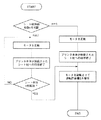
次に、上記インクジェットプリンタの動作を図7を参照しながら説明する。
【0014】
印刷指示が入力されたプリンタ本体2の制御手段は、シート材供給装置3の制御手段に対してシート材Pの供給を要求する。シート材Pの供給要求を受けたシート材供給装置3の制御手段は、要求されているシート材Pの枚数nがn=1であるか、n≧2であるかを判断する。そこで、n=1の場合の動作を先に説明し、次いでn≦2の場合の動作を説明する。
(n=1の場合)
(1)シート材供給装置3の制御手段はモータを正転させる。すると、第一伝達ギア23が回転すると共に、アーム17が下方へ回動して給送ローラ12がシート収容カセット11内の最上位のシート材Pの表面に押し付けられる。
(2)モータの回転駆動力は伝達手段21等を介して給送ローラ12に伝達され、シート材Pの表面に押し付けられている給送ローラ12を回転させる。この結果、シート材Pがシート材収納カセット11の送出し口14から送り出される。送り出されたシート材Pは、分離板15の抵抗を受けて最上位のシート材Pがそれより下位のシート材Pから分離され、最上位のシート材Pのみがプリンタ本体2のシート材搬送路Rに進入する。このとき、分離板15による分離性能の安定の観点からは、給送ローラ12の回転開始から最上位のシート材Pがシート材搬送路Rに進入する直前までの給送ローラ12の外周速度を3インチ/秒〜6インチ/秒とすることが望ましい。
(3)シート材搬送路Rに進入したシート材Pは、Uターンローラ27の回転によって搬送ローラ28とピンチローラ29との間に導かれ、これら搬送ローラ28とピンチローラ29とに挟まれた状態で記録ヘッド4と対向する記録位置に設けられたプラテン30上に搬送される。すると、プラテン30上に搬送されたシート材Pに対して、キャリア5に搭載された記録ヘッド4による印字(画像記録)が開始される。本実施形態では、記録ヘッド4による1走査分の印字が終了すると、一旦印字を中断し、プラテン30上のシート材Pを搬送ローラ28によって所定量だけ前方に搬送してから次の1走査分の印字を行う。
(4)シート材Pへの印字が全て終了すると、シート材排出ローラ31と拍車32とによって印字済のシート材Pがカセットカバー33上に排紙される。
(5)排紙が終了すると、シート材供給装置3の制御手段はモータを逆転させ、上記のようにして第一伝達ギア23と第二伝達ギア24との間に逆転許容量Sを発生させてからモータを停止する。ここで、逆転許容量Sは、給送時とは逆方向に移動されたシート材Pとの摩擦によって給送ローラ12が逆転されたときに発生する第二伝達ギア24の回転量以上に設定されている。ここで、シート材Pが給送時とは逆方向に移動される場合としては、シート収納カセット11をプリンタ本体2から引き抜く際やシート収納カセット11からシート材Pを取り出す際などがある。
【0015】
(n≧2の場合)
n≧2の場合の動作は、上記n=1の場合の動作と基本的に同一である。異なるのは、シート材Pがn枚給送されるまで上記(1)〜(4)の工程を繰り返し、その後に(5)の工程に移行することである。
【0016】
【発明の効果】
(1)本発明のシート材供給装置は、アームによって回転自在に保持された給送ローラをアームの自重及び下方動作によってシート材の表面に接触させ、シート材の表面に接触した給送ローラをモータの回転駆動力によって回転させてシート材を給送するシート材供給装置であって、モータを制御する制御手段と、モータの回転駆動力を給送ローラに伝達する第一の伝達手段と、モータの回転駆動力をアームを下方動作させる力に変換してアームに伝達する第二の伝達手段と、給送ローラがシート材の給送時とは反対方向に回転されたときに発生する回転力を吸収し、その回転力が第二の伝達手段を介してアームに伝達されることを阻止する空転手段とを備えている。従って、シート材を収納しているカセットを記録装置から抜き取ったり、カセットからシート材を取り出したりしたときに給送ローラが逆転しても、その回転力によってアームが下方動作することがない。このため、意に反して給送ローラがシート材に押し付けられ、シート材の移動が阻害される不都合がない。
(2)さらに、上記制御手段は、給送されるシート材が1枚のみの場合は、シート材の給送が終了するごとに上記空転手段を機能させ、給送されるシート材が2枚以上の場合は、全てのシート材の給送が終了した後に上記空転手段を機能させる。従って、連続印刷の際には、シート材が給送される度にではなく、全ての印刷ジョブが終了した後に上記空転手段が機能する。このため、印刷速度を低下させることなく上記(1)の効果を得ることができる。
【図面の簡単な説明】
【図1】本発明のシート材供給装置を備えたインクジェットプリンタの一例を示す一部省略の模式的斜視図である。
【図2】図1に示すインクジェットプリンタの模式的断面図である。
【図3】モータの回転駆動力をプーリに伝達する伝達手段の一部を示す模式的側面図である。
【図4】モータの回転駆動力をプーリに伝達する伝達手段の一例を示す模式的斜視図である。
【図5】(a)(b)は、シート材給送時の伝達ギアの動作を示す模式的平面図である。
【図6】逆転許容量発生時の伝達ギアの動作を示す模式的平面図である。
【図7】シート材供給装置の動作フローを示すチャート図である。
【符号の説明】
1 画像記録部
2 プリンタ本体
3 シート材供給装置
4 記録ヘッド
5 キャリア
6 フレーム
7 ガイドシャフト
8 ガイドレール
9 インクタンク
10 記録液供給チューブ
11 シート材収納カセット
12 給送ローラ
13 収納口
14 送出し口
15 分離板
16 支持ピン
17 アーム
18 プーリ
19 ベルト
20 ギア
21 伝達手段
22 シャフト
23 第一伝達ギア
24 第二伝達ギア
25 操作片
26 受動片
27 Uターンローラ
28 搬送ローラ
29 ピンチローラ
30 プラテン
31 シート排出ローラ
32 拍車
33 カセットカバー[0001]
TECHNICAL FIELD OF THE INVENTION
The present invention relates to a sheet material supply device suitable for supplying a sheet material as a recording medium to a recording device such as a printer, a copying machine, and a facsimile.
[0002]
[Prior art]
A recording device such as a printer, a copying machine, and a facsimile generally includes a sheet material supply device that stores a sheet material as a recording medium and feeds the stored sheet material by a feeding unit. Then, the sheet material supplied by the sheet material supply device is conveyed to the image recording unit by the conveying means, and the image recording unit records an image on the surface of the sheet material. Here, as one of the feeding means of the sheet material feeding device, a feeding roller rotatably supported by the arm is pressed against the surface of the sheet material by the weight of the arm and the downward turning operation, and the surface of the sheet material is pressed. There is a printer that obtains a feeding force by rotating a feeding roller pressed against a sheet (for example, see Patent Document 1). The feeding means having such a structure has an advantage that the structure is simpler than that of a feeding means having a structure in which a restoring force of an elastic body such as a spring is applied to a stacked sheet material to press the sheet material against a feeding roller. .
[0003]
[Patent Document 1]
Japanese Patent Laid-Open Publication No. Hei 10-81422
[Problems to be solved by the invention]
However, a sheet material feeding device having a structure in which a feeding roller rotatably supported by an arm is pressed against the surface of the sheet material by the weight of the arm and a downward rotating operation causes the following problems. was there. That is, in this type of feeding means, a rotational driving force for rotating the feeding roller is converted into a force for rotating the arm downward using a gear train. Therefore, when the sheet material is moved in the opposite direction to the feeding direction and the feeding roller rotates in the direction opposite to the feeding direction due to the friction between the sheet material and the feeding roller, the rotational force is applied to the gear train. The force is converted into a force for rotating the arm downward, and acts on the arm. As a result, the arm pivots downward contrary to will, the feed roller is pressed against the surface of the sheet material, and the movement of the sheet material is hindered. For example, when removing the cassette in which the stacked sheet materials are stored from the recording apparatus, the movement of the uppermost sheet material is hindered by the feeding roller pressed against the surface thereof, and the movement of the uppermost sheet material is hindered. There is a problem that the sheet material (or several sheet materials including the uppermost sheet material) remains inside the recording apparatus. An object of the present invention is to provide a sheet material supply device that solves this problem.
[0005]
[Means for Solving the Problems]
In order to achieve the above object, the sheet feeding apparatus of the present invention is configured such that a feed roller rotatably held by an arm is brought into contact with the surface of the sheet by its own weight and downward operation of the arm, and the sheet is fed to the surface of the sheet. A sheet material feeding device for feeding a sheet material by rotating the feeding roller contacted by a rotation driving force of a motor, the control device controlling the motor, and the feeding roller rotating drive force of the motor. A first transmission means for transmitting the sheet material to the arm; a second transmission means for converting the rotational driving force of the motor into a force for moving the arm downward and transmitting the force to the arm; An idler for absorbing a rotational force generated when rotated in a direction opposite to the time, and preventing the rotational force from being transmitted to the arm via the second transmitter. When only one sheet material is fed, the idler is activated each time the feeding of the sheet material ends, and when two or more sheet materials are fed, all the sheet materials are used. After the completion of the feeding, the idling means is operated. Therefore, even if the feeding roller is rotated in the reverse direction by moving the sheet material in the direction opposite to the feeding direction, the rotational force is absorbed by the idling means and is not converted into the force for moving the arm downward.
[0006]
BEST MODE FOR CARRYING OUT THE INVENTION
Hereinafter, an embodiment of the present invention will be described in detail with reference to the drawings. What is described here is an ink jet printer which is an example of a recording apparatus provided with the sheet material supply device of the present invention. As shown in FIG. 1, the ink jet printer is roughly divided into a printer main body 2 having an image recording section 1 and a sheet material supply device 3 for supplying a sheet material P as a recording medium to the printer main body 2.
[0007]
The image recording section 1 of the printer main body 2 includes a recording head 4 and a carrier 5 on which the recording head 4 is mounted. The carrier 5 is supported by a parallel guide shaft 7 and guide rails 8, both ends of which are fixed to a frame 6, so as to be able to reciprocate in a direction (main scanning direction) orthogonal to the sheet material P conveying direction. Further, in the recording head 4, a plurality of nozzle rows composed of a plurality of nozzles arranged along the conveying direction (sub-scanning direction) of the sheet material P are arranged at equal intervals in the main scanning direction, and are different from each nozzle row. The color ink is ejected. Inks of each color are supplied to the nozzles in each nozzle row from an ink tank 9 set in the printer main body 2 via a recording liquid supply tube 10. Therefore, an image is recorded on the surface of the sheet material P by ejecting ink from the nozzle row of the recording head 4 toward the sheet material P while reciprocating the carrier 5 in the main scanning direction. The carrier 5 is reciprocated in the main scanning direction by a drive mechanism (not shown). The ink tank 9 is detachable from the printer main body 2 and is replaced as needed.
[0008]
As shown in FIG. 2, the sheet material supply device 3 supplies a sheet storage cassette 11 as sheet material storage means detachable to the printer main body 2 and a sheet material P stored in the sheet storage cassette 11 to the printer main body 2. A feeding roller 12 is provided as feeding means for feeding. The sheet storage cassette 11 is a plastic box having a substantially rectangular planar shape, and one of four side surfaces and an upper surface are opened. The opened upper surface functions as a storage port 13 for storing the sheet material P in the sheet storage cassette 11, and the opened side surface functions as a delivery port 14 for sending out the stored sheet material P to the printer main body 2. A separation plate 15 is provided at the end of the discharge port 14 so as to abut on the back surface of the sheet material P passing therethrough and to separate the uppermost sheet material P from the lower sheet material P.
[0009]
The feeding roller 12 has an arm 17 whose one end is rotatably supported by a support pin 16 located above the sheet storage cassette 11 and upstream of the feeding roller 12 in the feeding direction of the sheet material P. It is rotatably held at the end. At the time of feeding the sheet material P, the arm 17 is pressed against the surface of the uppermost sheet material P in the sheet storage cassette 11 by its own weight and the downward rotating operation, and the pulley 18 and the belt 19 shown in FIG. The sheet material P is rotated in a direction indicated by an arrow in the figure by a rotational driving force transmitted from a driving source (motor) (not shown) via a transmitting means including a gear 20 and exerts a feeding force for feeding the sheet material P to the printer main body 2. . A part of the rotational driving force of the motor is converted into a force for rotating the arm 17 downward by a transmitting means (not shown) having a gear train and transmitted to the arm. The motor is controlled by control means (not shown).
[0010]
Transmission means for transmitting the rotational driving force of the motor to the pulley 18 is provided between the motor and the pulley 18. FIG. 4 shows an example of the configuration of this transmission means. The transmission means 21 shown in FIG. 4 includes a first transmission gear 23 integrally fixed to a shaft 22 directly or indirectly connected to a rotation shaft of the motor, and a free-rotationally mounted on the shaft 22, and a circumferential surface of which is connected to the pulley 18. And a second transmission gear 24 in contact with the peripheral surface of the second transmission gear 24. Further, an operation piece 25 is integrally formed on a side surface of the first transmission gear 23 facing the second transmission gear 24. On the side surface of the second transmission gear 24 facing the side surface of the first transmission gear 23, there is provided a passive piece 26 extending in the direction of the first transmission gear 23 so that the tip is located on the rotation track of the operation piece 25. It is formed integrally. When the motor rotates forward, Fig 5 (a), the shaft 22 is rotated in the arrow A 1 direction in the drawing operation is formed on the first transmission gear 23 and the first transmission gear 23 The piece 25 also rotates in the same direction. Furthermore, the operation piece 25 is rotated in the arrow A 1 direction by a predetermined amount, as shown in FIG. 5 (b), rotates the passive piece 26 in the same direction in contact with the passive piece 26. Then, the passive piece 26 and the second transmission gear 24 integral (see FIG. 4) rotates in the same direction, and has a pulley 18 in contact with the second transmission gear 24 is rotated in the arrow B 1 direction. As a result, the rotational driving force of the motor is transmitted to the feeding roller 12 via a belt 19 and a gear 20 shown in FIG. 3, the feeding roller 12 is rotated in the arrow C 1 direction in FIG. 5 (b).
[0011]
In the transmission means 21 having the above-described configuration, the operation piece 25 is in contact with the passive piece 26 when the feeding of the sheet material P is completed (see FIG. 5B). Therefore, in this state, if the feeding roller 12 tries to rotate in the opposite direction to the feeding, the pulley 18 also tries to rotate in the opposite direction to the feeding, and the second transmission gear 24 also rotates in the opposite direction to the feeding. The passive piece 26 formed on the second transmission gear 24 also tries to rotate in the direction opposite to the direction during feeding. As a result, the operation piece 25 that is in contact with the passive piece 26 tries to rotate in the opposite direction to that during feeding, and the first transmission gear 23 on which the operation piece 25 is formed rotates in the opposite direction to that during feeding. The shaft 22 is also subjected to a force to rotate in a direction opposite to the direction at the time of feeding. However, since the motor connected to the shaft 22 is stopped, a force for rotating the shaft 22 is converted into a force for rotating the arm 17 downward by the transmission means, and is transmitted to the arm 17. . That is, the rotational force generated by the reverse rotation of the feed roller 12 finally acts as a force for pressing the feed roller 12 against the surface of the sheet material P, and hinders the movement of the sheet material P.
[0012]
Therefore, in the sheet material supply device of the present invention, when a rotational force is applied to the pulley 18 in a direction opposite to that at the time of feeding, the second transmission gear 24 idles on the shaft 22, and the rotational force is transmitted to the shaft 22. It is equipped with an idling means to prevent the rotation. Specifically, as shown in FIG. 6, when the feeding of the sheet material P is completed, the control unit rotates the motor in the reverse direction, and moves the first transmission gear 23 in a direction opposite to the feeding direction (arrow in FIG. 6). by rotating by a predetermined amount in a 2 direction), release the operating piece 25 of the passive piece 26 was in contact with the passive piece 26. As a result, the reverse rotation allowable amount S is generated between the first transmission gear 23 and the second transmission gear 24 (between the operation piece 25 and the passive piece 26). Therefore, the time the feeding roller 12 is fed to rotate in the reverse direction reverse to the case feed pulley 18 sheet by rotating (arrow C 2 direction in FIG. 6) (arrow B 2 direction in FIG. 6) , along with this also the time the second transmission gear 24 is feeding is rotated in the reverse direction (arrow a 2 direction in FIG. 6), as long as the amount of rotation is less than the reverse tolerance S, the second transmission The gear 24 only idles on the shaft 22, and neither the first transmission gear 23 nor the shaft 22 rotates. That is, the rotational force generated by the reverse rotation of the feed roller 12 is absorbed by the idling of the second transmission gear 24, is not converted to the force for rotating the arm 17 downward, and is not transmitted to the arm 17.
[0013]
Next, the operation of the inkjet printer will be described with reference to FIG.
[0014]
The control means of the printer body 2 to which the print instruction has been input requests the control means of the sheet material supply device 3 to supply the sheet material P. The control means of the sheet material supply device 3 having received the sheet material P supply request determines whether the requested number n of the sheet materials P is n = 1 or n ≧ 2. Therefore, the operation when n = 1 will be described first, and then the operation when n ≦ 2 will be described.
(When n = 1)
(1) The control means of the sheet supply device 3 rotates the motor forward. Then, while the first transmission gear 23 rotates, the arm 17 rotates downward, and the feeding roller 12 is pressed against the surface of the uppermost sheet material P in the sheet storage cassette 11.
(2) The rotational driving force of the motor is transmitted to the feed roller 12 via the transmission means 21 and the like, and rotates the feed roller 12 pressed against the surface of the sheet material P. As a result, the sheet material P is sent out from the outlet 14 of the sheet material storage cassette 11. The fed sheet material P is separated from the lowermost sheet material P by the resistance of the separating plate 15 due to the resistance of the separating plate 15, and only the highest sheet material P is transferred to the sheet conveying path of the printer body 2. Enter R. At this time, from the viewpoint of the stability of the separation performance of the separation plate 15, the outer peripheral speed of the feed roller 12 from the start of rotation of the feed roller 12 to immediately before the uppermost sheet material P enters the sheet material conveyance path R is determined. It is desirable to set it to 3 inches / second to 6 inches / second.
(3) The sheet material P that has entered the sheet material conveyance path R is guided between the conveyance roller 28 and the pinch roller 29 by the rotation of the U-turn roller 27, and is sandwiched between the conveyance roller 28 and the pinch roller 29. In this state, the sheet is conveyed onto a platen 30 provided at a recording position facing the recording head 4. Then, printing (image recording) on the sheet material P conveyed on the platen 30 by the recording head 4 mounted on the carrier 5 is started. In this embodiment, when printing for one scan by the recording head 4 is completed, printing is temporarily interrupted, the sheet material P on the platen 30 is transported forward by a predetermined amount by the transport roller 28, and then the next one scan is performed. Is printed.
(4) When all printing on the sheet material P is completed, the printed sheet material P is discharged onto the cassette cover 33 by the sheet material discharge roller 31 and the spur 32.
(5) When the discharge is completed, the control means of the sheet material supply device 3 reverses the motor to generate the reverse rotation allowable amount S between the first transmission gear 23 and the second transmission gear 24 as described above. And then stop the motor. Here, the reverse rotation allowable amount S is set to be equal to or larger than the rotation amount of the second transmission gear 24 generated when the feed roller 12 is reversely rotated due to friction with the sheet material P moved in the direction opposite to the feeding direction. Have been. Here, as a case where the sheet material P is moved in the opposite direction to the time of feeding, there are a case where the sheet storage cassette 11 is pulled out from the printer main body 2 and a case where the sheet material P is taken out from the sheet storage cassette 11.
[0015]
(When n ≧ 2)
The operation when n ≧ 2 is basically the same as the operation when n = 1. The difference is that the steps (1) to (4) are repeated until n sheets P are fed, and thereafter, the process proceeds to the step (5).
[0016]
【The invention's effect】
(1) The sheet material supply device of the present invention causes a feeding roller rotatably held by an arm to contact the surface of the sheet material by its own weight and downward operation of the arm. A sheet material feeding apparatus that feeds a sheet material by rotating the sheet with a rotational driving force of a motor, and a control unit that controls the motor, and a first transmitting unit that transmits a rotational driving force of the motor to a feeding roller. A second transmitting means for converting the rotational driving force of the motor into a force for moving the arm downward and transmitting the force to the arm; and a rotation generated when the feeding roller is rotated in a direction opposite to the direction in which the sheet material is fed. Idle means for absorbing the force and preventing the rotational force from being transmitted to the arm via the second transmission means. Therefore, even if the feed roller is reversed when the cassette containing the sheet material is removed from the recording apparatus or when the sheet material is removed from the cassette, the arm does not move downward due to the rotational force. For this reason, there is no inconvenience that the feeding roller is pressed against the sheet material and the movement of the sheet material is hindered.
(2) Further, when only one sheet material is fed, the control means causes the idle means to function each time the feeding of the sheet material ends, and the number of fed sheet materials is two. In the above case, the idling means is operated after all the sheet materials have been fed. Therefore, in continuous printing, the idle rotation unit functions not after every sheet material is fed but after all print jobs are completed. For this reason, the effect (1) can be obtained without lowering the printing speed.
[Brief description of the drawings]
FIG. 1 is a schematic perspective view, partially omitted, showing an example of an ink jet printer including a sheet material supply device of the present invention.
FIG. 2 is a schematic sectional view of the ink jet printer shown in FIG.
FIG. 3 is a schematic side view showing a part of a transmission unit that transmits a rotational driving force of a motor to a pulley.
FIG. 4 is a schematic perspective view illustrating an example of a transmission unit that transmits a rotational driving force of a motor to a pulley.
FIGS. 5A and 5B are schematic plan views illustrating the operation of a transmission gear when feeding a sheet material.
FIG. 6 is a schematic plan view showing an operation of a transmission gear when a reverse rotation allowable amount is generated.
FIG. 7 is a chart showing an operation flow of the sheet material supply device.
[Explanation of symbols]
DESCRIPTION OF SYMBOLS 1 Image recording part 2 Printer main body 3 Sheet material supply device 4 Recording head 5 Carrier 6 Frame 7 Guide shaft 8 Guide rail 9 Ink tank 10 Recording liquid supply tube 11 Sheet material storage cassette 12 Feeding roller 13 Storage port 14 Delivery port 15 Separating plate 16 Support pin 17 Arm 18 Pulley 19 Belt 20 Gear 21 Transmission means 22 Shaft 23 First transmission gear 25 Second transmission gear 25 Operation piece 26 Passive piece 27 U-turn roller 28 Transport roller 29 Pinch roller 30 Platen 31 Sheet discharge roller 32 spurs 33 cassette cover