JP2004338738A - Packaging film and package - Google Patents
Packaging film and package Download PDFInfo
- Publication number
- JP2004338738A JP2004338738A JP2003135605A JP2003135605A JP2004338738A JP 2004338738 A JP2004338738 A JP 2004338738A JP 2003135605 A JP2003135605 A JP 2003135605A JP 2003135605 A JP2003135605 A JP 2003135605A JP 2004338738 A JP2004338738 A JP 2004338738A
- Authority
- JP
- Japan
- Prior art keywords
- packaging film
- packaged
- package
- laminated
- film
- Prior art date
- Legal status (The legal status is an assumption and is not a legal conclusion. Google has not performed a legal analysis and makes no representation as to the accuracy of the status listed.)
- Pending
Links
Images


Abstract
Description
【0001】
【発明の属する技術分野】本発明は、包装フィルム及び包装体に関し、更に詳しくは、テープロール等の単位被包装物品を積層した積層体を包装したときに、容易に開裂させて中の単位被包装物品を取り出すことができるとともに、開裂したときに中の単位被包装物品がバラバラにならずに使用する分だけを取り出すことができる包装フィルムと、そのような包装フィルムで単位被包装物品を積層した積層体を包装した包装体に関する。
【0002】
【従来の技術】従来、片面粘着テープや両面粘着テープを紙管等に巻き付けて形成されるテープロール等の被包装物品を包装するときには、複数の被包装物品を紙で包んだり、袋に入れて包装することにより包装体とする等の方法が採られていた。しかし、紙で包装するときには手作業で包装しなければならず、包装工程を自動化することができないため生産性が悪いという問題があった。また、袋に入れるときには、全体の体積が大きくなり、嵩張るため保管等に不便であった。
【0003】そこで、上述のテープロール等のような、それぞれが別体の筒状の単位被包装物品を、複数積層して積層被包装物品(テープロール等を複数本重ねたもの)として包装しようとするときには、テープロール等の単位被包装物品を複数本重ねてなる積層被包装物品を、筒状の熱収縮フィルムで包み込み、外部側から熱を加えて積層被包装物品を包装して、積層被包装物品表面上に包装フィルムを形成した包装体とする方法が採られている。従来より、熱収縮フィルムは、被包装物品を包装するための包装フィルムとして使用されており、熱収縮フィルムを使用することにより、被包装物品の包装を機械により自動的に行うことができる(例えば、特許文献1,2参照)。
【0004】しかし、筒状の熱収縮フィルム(包装フィルム)で積層被包装物品を包装して包装体を形成したときには、包装体を開包して積層被包装物品又は単位被包装物品を取り出して使用するときに包装フィルムを手で切り離す作業が容易ではなかった。包装フィルムを手で容易に取り外すことができないため、ナイフ、はさみ等の刃物で切る必要があるという問題があった。また、むりやり手で包装フィルムを取り外そうとすると、強い力で引き千切る必要があり、開包作業が容易ではなく、場合によっては積層被包装物品又は単位被包装物品が変形する等の問題があった。
【0005】そこで、筒状の包装フィルムを容易に積層被包装物品から取り外すことができるようにするために、筒状の包装フィルムの軸方向に沿ってミシン目を備える方法が採られている。この筒状の包装フィルムの軸方向に沿ってミシン目を備える方法は、例えばペットボトルのラベルとして筒状の熱収縮フィルムを使用した場合にも採用されている(例えば、特許文献3参照)。このようなミシン目を備えることにより、ミシン目の部分が容易に破断するため、手で容易に包装フィルム(熱収縮フィルム)を取り外すことが可能となる。
【0006】しかし、このように、筒状の包装フィルム(熱収縮フィルム)の軸方向に沿ってミシン目を備え、そのミシン目から破断させると、被包装物品(積層被包装物品、ペットボトル等)と包装フィルム(熱収縮フィルム)とが完全に分離してしまうため、ペットボトルから筒状の熱収縮フィルムを取り外す場合のように一度に完全に取り外したいときには好都合であるが、包装体(積層被包装物品)から単位被包装物品を1つずつ取り出して使用したいときには、使用する単位被包装物品だけでなく使用しない単位被包装物品までもがバラバラになるという問題があった。つまり、包装体から包装フィルムが完全に分離されると、包装フィルムで包装されることにより一体となっていた複数の単位被包装物品(テープロール等)がバラバラになるため、開包時の作業性が悪く、また開包後、使用しない単位被包装物品の収納、保管がし難くなるという問題があった。例えば、工事現場等で、現場作業者が作業中に包装体から包装フィルムを取り外すと、作業中に単位被包装物品(テープロール等)がバラバラになることになるため、単位被包装物品が落下する等により作業性が非常に悪くなり、これらバラバラになった単位被包装物品を改めてかたづける必要も生じるという問題があった。また、単位被包装物品がバラバラになると、それぞれが非常に汚れやすい状態となるという問題もあった。
【0007】
【特許文献1】
特開平7−32503号公報
【特許文献2】
特開平8−91431号公報
【特許文献3】
特開2002−326638号公報
【0008】
【発明が解決しようとする課題】本発明は、このような従来技術の有する問題点に鑑みてなされたものであり、その目的とするところは、テープロール等の単位被包装物品を複数積層した積層被包装物品を包装したときに、容易に破断させて中の単位被包装物品を取り出すことができるとともに、破断したときに中の単位被包装物品がバラバラにならずに使用する分だけを取り出すことができる包装フィルムと、そのような包装フィルムで単位被包装物品を複数積層した積層被包装物品を包装した包装体を提供することにある。
【0009】
【課題を解決するための手段】上記目的を達成するため、本発明によって以下の包装フィルム及び包装体が提供される。
【0010】
[1] 筒状の熱収縮フィルムの内部に、それぞれ別体の筒状又は柱状の単位被包装物品が複数積層された積層被包装物品を収納し、前記熱収縮フィルムを前記積層被包装物品の外部側から熱収縮させて前記積層被包装物品を包装することにより、前記積層被包装物品表面上に形成される筒状の包装フィルムであって、その筒状の側面部の少なくとも1箇所に、その周方向に形成された、開包時に容易に破断されることが可能な破断部を備えてなることを特徴とする包装フィルム。
【0011】
[2] 前記破断部が、前記筒状の側面部の周方向に形成された、ミシン目、スクラッチ又は切り欠きである[1]に記載の包装フィルム。
【0012】
[3] 前記単位被包装物品が、円筒状のテープロールであり、前記積層被包装物品が、前記テープロールが複数積層された円筒体である[1]又は[2]に記載の包装フィルム。
【0013】
[4] [1]〜[3]のいずれかに記載の包装フィルムに、それぞれ別体の筒状又は柱状の単位被包装物品が複数積層された積層被包装物品が包装されてなることを特徴とする包装体。
【0014】このように、本発明の包装フィルムは、その筒状の側面部の少なくとも1箇所に、開包時に容易に破断されることが可能な、その周方向に形成された破断部を備えてなるため、単位被包装物品を複数積層した積層被包装物品を包装したときに、容易に破断させて中の単位被包装物品を取り出すことができるとともに、破断したときに中の単位被包装物品がバラバラにならずに使用する分だけを取り出すことができる。また、本発明の包装体は、上記本発明の包装フィルムで単位被包装物品を複数積層した積層被包装物品を包装してなるため、包装フィルムを容易に破断させて中の単位被包装物品を取り出すことができるとともに、破断したときに中の単位被包装物品がバラバラにならずに使用する分だけを取り出すことができる。
【0015】
【発明の実施の形態】次に本発明の実施の形態を図面を参照しながら詳細に説明するが、本発明は以下の実施の形態に限定されるものではなく、本発明の趣旨を逸脱しない範囲で、当業者の通常の知識に基づいて、適宜設計の変更、改良等が加えられることが理解されるべきである。
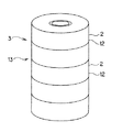
【0016】図1は、本発明の包装フィルムの一の実施の形態で積層被包装物品を包装した包装体を示す斜視図である。
【0017】図1に示すように、本実施の形態の包装フィルム1は、筒状の透明のポリエチレンテレフタレート製熱収縮フィルムの内部に、それぞれ別体の筒状の単位被包装物品2(テープロール12)が複数積層された積層被包装物品3(円筒体13)を収納し、熱収縮フィルムを円筒体13の外部側から熱収縮させて円筒体13を包装することにより、円筒体13の表面上に形成されるものである。そして、図1及び図2に示すように、筒状の透明の包装フィルム1の側面部5の、中心軸方向の略中央部分に、包装フィルム1の周方向に破断部4(ミシン目14)を備えている。また、包装フィルム1で円筒体13を包装することにより、筒状の包装体20が形成されている。本実施の形態において、単位被包装物品2であるテープロール12は、図3に示すように、紙管6の周囲にテープ(片面粘着テープ)7を捲回することにより形成された円筒状のテープロールである。そして、積層被包装物品3である円筒体13は、図4に示すように、単位被包装物品2であるテープロール12を、その中心軸方向に5段積層して得られた円筒体である。
【0018】このように、本実施の形態の包装フィルム1は、その筒状の側面部5の少なくとも1箇所に、開包時に容易に破断されることが可能な、その周方向に形成された破断部4を備えてなるため、単位被包装物品2を複数積層した積層被包装物品3を包装したときに、容易に破断させて中の単位被包装物品2を取り出すことができるとともに、破断したときに中の単位被包装物品2がバラバラにならずに使用する分だけを取り出すことができる。そして、単位被包装物品2の使用されない分は、破断された包装フィルム1に保持された状態になるため、埃や汚れの付着を防ぐことができる。
【0019】本実施の形態の包装フィルム1は、筒状の熱収縮フィルムの内部に円筒体13を収納し、熱収縮フィルムを円筒体13の外部側から熱収縮させて円筒体13の表面上に形成されたものであるため、包装フィルム1により円筒体13を、円筒体13の外側から適度に締め付けるように包装することができる。
【0020】本実施の形態の包装フィルム1に備えられている破断部4は、図1に示すように1箇所に形成されていてもよいが、複数箇所に形成されていてもよい。破断部の数は特に限定されるものではなく、包装フィルム1の中心軸方向の長さや包装フィルム1に収納される単位被包装物品2の数等により適宜決定することができるが、1〜10箇所が好ましい。素手で破断させるときの作業性や、破断させた後の作業性等を向上させるために、少なくとも包装フィルム1の中心軸方向の略中央部に1箇所破断部4が形成されることが好ましい。
【0021】破断部4は、図1に示すようにミシン目14であってもよいが、スクラッチや切り欠きであってもよい。ここで、ミシン目とは、図1に示すように線状の切り込みを一定の間隔で形成するものである。切り込みは包装フィルムを貫通し、切り込みと切り込みとの間隔は一定であることが好ましいが、包装フィルムを容易に破断することができれば必ずしも一定である必要はない。切り込みの長さは、1〜5mmであることが好ましい。また、切り込みと切り込みとの間隔(切り込みが入っていない部分の長さ)は、2〜3mmであることが好ましい。
【0022】スクラッチとは、ミシン目のように包装フィルムを貫通する切り込みが形成されるものではなく、包装フィルムの表面に線状の傷(主として貫通しないもの)を形成し、その傷をきっかけにして包装フィルムが破断するものである。上記傷の形態としては、一本の線状であってもよいが、複数本の線の集まりや、多数の細かい傷の集まりにより全体で線状に形成されていてもよい。また、部分的に包装フィルムを貫通していてもよく、全体で一本の線ではなく、断続的な線(破線)を形成してもよい。
【0023】切り欠きとは、ミシン目における線状の切り込みを、円形、三角形、くさび形、ひし形等の、破断し易い形状の貫通孔としたものである。すなわち、上記形状の貫通孔を包装フィルムに一定の間隔で形成したものである。貫通孔と貫通孔との間隔は一定であることが好ましいが包装フィルムを容易に破断することができれば必ずしも一定である必要はない。貫通孔の周方向(包装フィルムの周方向)の長さは、1〜5mmであることが好ましい。また、貫通孔と貫通孔との間隔は、2〜3mmであることが好ましい。また、貫通孔としては、針を包装フィルムに突き刺したときに形成されるような、包装フィルムが小さく裂けることにより形成される小さな針穴であってもよい。この場合、針穴の周方向に裂ける長さは1〜2mmであることが好ましい。そして、針穴と針穴との間隔は、1〜2mmであることが好ましい。
【0024】図1に示す本実施の形態の包装フィルム1は、上述のような破断部4を備えるため、作業者が素手で、破断部4側が開くように包装体20を折り曲げることにより、容易に破断部4を破断し、テープロール12を取り出すことができる。
【0025】図1に示す破断部4は、包装フィルム1の周方向に沿って形成されているため、包装体20を破断部4側が開くように折り曲げ、包装フィルム1が破断部4より破断されるときに、包装フィルム1が、その一部を残してその周方向に沿って裂かれ、包装体20が2つ折りになる。つまり、筒状の包装体20が、2つの、分割された筒状の包装体(分割包装体)になり、その2つの分割包装体を繋ぐように、包装フィルム1の一部が繋がる構造になる。このように形成された2つの分割包装体は、包装フィルム1の一部が繋がっているため、完全には分離されずに全体としては一体に形成されている。ここで、破断部4が包装フィルム1の周方向に沿って形成されるとは、完全に周方向に一致する方向に形成される必要はなく、包装体20を2つ折りにしたときに、包装フィルム1の切断部分が斜めになっていても、2つの分割包装体が形成され、それぞれの分割包装体の中の単位被包装物品2がバラバラにならずに使用する分だけを取り出すことができればよい。
【0026】周方向に形成される破断部4は、包装フィルム1の全周に渡って形成されていてもよいが、図1及び図2に示すように、全周のなかで、破断部4を形成しない部分を残して、一部に形成されることが好ましい。このように、破断部4を周方向の一部に形成することにより、包装体20を折り曲げたときに、破断部4が形成されていない部分が繋がった状態になるため、上述のように、2つの分割包装体が全体として一体に形成され易くなる。破断部4が形成される範囲は、全周の長さ(破断部4が周方向に対して斜めに形成されているときは、その斜め方向を延長したときの一週分の長さ)に対して、10〜90%の範囲であることが好ましく、30〜70%の範囲であることが更に好ましい。10%より短いと、破断部4から破断し難いことがあり、90%より長いと、包装体20を折り曲げたときに、包装フィルム1の繋がった部分が弱くなることがある。
【0027】周方向に形成される破断部4は、積層された単位被包装物品2の境界部分に重なる位置に形成されてもよいし、図1に示すように、単位包装物品2に重なる位置(図1では、単位包装物品2の中心軸方向の中央部付近)に形成されてもよい。
【0028】また、各分割包装体中の2つに分離した円筒体13のそれぞれは、略中央部分で破断して2つに分割された包装フィルム1(一部は繋がっている)で適度に締め付けられた状態であるため、それぞれの包装フィルム1の中にテープロール12が柱状に積み重なった状態で保持される。そして、テープロール12は、2つに分割された包装フィルム1の破断により形成された側の端部から1本ずつ手で取り出すことができる。従って、包装フィルム1で円筒体13を締め付けるときの強さは、テープロール12が容易にはバラバラにならず、かつ、テープロール12を手で取り出せる程度にすることが好ましい。
【0029】また、包装フィルム1により円筒体13を包装するときには、図1に示すように、円筒体13の両端面の少なくとも一部を包装フィルム1が覆うことが好ましい。このように、円筒体13の両端面の少なくとも一部を包装フィルム1が覆うことにより、包装体20が形成されたときに、円筒体13の両端部に位置するテープロール12が包装フィルム1から抜け落ちることを防止することができる。
【0030】図1及び図4に示す本実施の形態の包装フィルム1の材質としては、上述のようにポリエチレンテレフタレートが好ましいが、熱収縮フィルムであれば特に限定されるものではなく、例えば、ポロプロピレン、ポリエチレン、ポリスチレン、ポリアミド、エチレン酢酸ビニル共重合体、環状オレフィン系コポリマー樹脂、その他のオレフィン系樹脂、塩化ビニル樹脂等が挙げられる。また、包装フィルム1は、用途に合わせて、単層フィルムであってもよいし、多層フィルムであってもよい。そして、包装フィルム1は、図1に示すように透明であってもよいが、半透明や透明でないものであってもよい。
【0031】包装フィルム1は、一軸延伸加工、二軸延伸加工等の通常の方法により製造することができる。
【0032】本実施の形態の包装フィルムは、上述のように、テープロール等の単位被包装物品を積層して包装するときに好適に使用される。テープロールとしては、特に限定されるものではなく、和紙テープやビニールテープ等いずれのテープロールをも包装することができる。また、テープロールの他にも、缶詰等を積層して包装する場合に好適に使用することができる。単位被包装物品は、円筒状や円柱状が好ましいが、底面が四角形、五角形等の多角形の筒状や、底面が四角形、五角形等の多角形の柱状であってもよい。また、積層される複数の単位被包装物品は、全てが同じ形状であることが、包装体にしたときの収納スペースが小さくできることや、包装の強度が強く、耐久性が良好である点で好ましいが、異なる形状のものが含まれていてもよい。また、本実施の形態の包装フィルムによる包装は、単位被包装物品を3個以上積層して包装する場合に、開包時に単位被包装物品がバラバラにならないという点でより有効である。
【0033】図1に示す円筒体13を、包装フィルム1を構成する熱収縮フィルムで包装して、円筒体13の表面上に形成される筒状の包装フィルム1を作製する方法は、特に限定されるものではなく、通常、熱収縮フィルムで被包装物品を包装する方法を採用することができる。例えば、まず、図5(a)に示すように、帯状の熱収縮フィルム(帯状熱収縮フィルム)22と、破断部(図示せず)がその幅方向中央部付近の位置に長さ方向に沿って形成された、破断部付き帯状熱収縮フィルム21とで挟むように、これらの長さ方向に沿って円筒体13を一列に配置する。ここで、図5(a)、図5(b)は、本実施の形態の包装フィルムを作製する工程を示し、円筒体13を熱収縮フィルムで包装する方法を模式的に示す平面図である。
【0034】帯状熱収縮フィルム22及び破断部付き帯状熱収縮フィルム21はその幅方向長さが略同じ長さである。そして、その幅方向長さは、円筒体13の中心軸方向長さより若干長く、帯状熱収縮フィルム22及び破断部付き帯状熱収縮フィルム21の幅方向両端部が円筒体13の両端部からはみ出すように配置する。これにより、熱収縮フィルムを熱収縮させて包装フィルムとするときに、包装フィルムの両端部が円筒体の両端面のそれぞれの少なくとも一部を覆うようにすることができる。
【0035】そして、図5(a)に示すように、帯状熱収縮フィルム22と破断部付き帯状熱収縮フィルム21のそれぞれの端部同士を、それぞれの幅全体に渡って熱融着させて、第一接続部23を形成する。
【0036】次に、図5(b)に示すように、帯状熱収縮フィルム22と破断部付き帯状熱収縮フィルム21とで、円筒体13の側面部分を包むように巻き、所定の位置で、帯状熱収縮フィルム22と破断部付き帯状熱収縮フィルム21を、それぞれの幅全体に渡って熱融着させて、第二接続部24を形成する。このとき、第二接続部24を形成する所定の位置によって、得られる包装フィルムに形成される破断部の長さが決定される。つまり、破断部付き帯状熱収縮フィルム21が、円筒体13の側面部分を巻く長さ(周方向長さ)が破断部の長さになるため、第二接続部24を形成する所定の位置を調節することによって、破断部付き帯状熱収縮フィルム21の長さを調節し、それにより破断部の長さを調節することができる。
【0037】また、これにより、帯状熱収縮フィルム22と破断部付き帯状熱収縮フィルム21とが、第一接続部及び第二接続部で接続されて、熱収縮フィルムが円筒体13の側面部分を取り囲むように円筒状に形成される。そして、接続部24の部分を、帯状熱収縮フィルム22及び破断部付き帯状熱収縮フィルム21の幅方向に沿って切断することにより、円筒状の熱収縮フィルムの内部に円筒体13が収納された包装物を、帯状熱収縮フィルム22及び破断部付き帯状熱収縮フィルム21から切り離された状態で得ることができる。
【0038】そして、上記得られた包装物を外部側から熱収縮させて、図1に示すような、円筒体13の表面上に形成される筒状の包装フィルム1が作製される。
【0039】図5(b)に示す第二接続部24の部分を切断して、上記包装物を切り離すときには、後に残る帯状熱収縮フィルム22と破断部付き帯状熱収縮フィルム21とがそれぞれの端部で、第二接続部24の位置で接続された状態になるようにする。それにより、上記包装物を切り離した後の帯状熱収縮フィルム22及び破断部付き帯状熱収縮フィルム21は、再び、図5(a)に示すように、それぞれの端部が第一接続部23(もとの第二接続部24の部分)で接続された構造とすることができる。そして再び、上述のように、所定の位置に第二接続部24(図5(b)参照)を形成し、図1に示す包装フィルム1を作製することができ、これらの操作を繰り返すことにより包装フィルム1(図1参照)を効率的に作製することができる。
【0040】また、図1に示す円筒体13を、包装フィルム1を構成する熱収縮フィルムで包装して、円筒体13の表面上に形成される筒状の包装フィルム1を作製する方法としては、筒状の熱収縮フィルムを作製し、その内部に円筒体を挿入して、外部から加熱し熱収縮フィルムを収縮させることにより、包装フィルムを作製してもよい。
【0041】次に、本発明の包装体の一の実施の形態について図面を参照しながら説明する。図6は、本発明の包装体の一の実施の形態を示す斜視図である。本実施の形態の包装体50は、図6に示すように、上述した本発明の包装フィルム31に、それぞれ別体の筒状又は柱状の単位被包装物品32(テープロール42)が複数積層された積層被包装物品33(円筒体43)が包装されてなることを特徴とする。
【0042】このように、本実施の形態の包装体50は、上述した本発明の包装フィルム31で単位被包装物品32を複数積層した積層被包装物品33を包装してなるため、包装フィルム31を容易に破断させて中の単位被包装物品32を取り出すことができるとともに、破断したときに中の単位被包装物品32がバラバラにならずに使用する分だけを取り出すことができる。そして、単位被包装物品32の使用されない分は、破断された包装フィルム31に保持された状態になるため、埃や汚れの付着を防ぐことができる。
【0043】本実施の形態の包装体50は、筒状の熱収縮フィルムの内部に円筒体43を収納し、熱収縮フィルムを円筒体43の外部側から熱収縮させて円筒体43の表面上に包装フィルム31を形成してなるものであるため、包装フィルム31により円筒体43を、円筒体43の外側から適度に締め付けるように包装したものである。
【0044】図6に示すように、本実施の形態の包装体50は、筒状の包装フィルム31の側面部35の中心軸方向の略中央部分に、包装フィルム31の周方向に破断部34(ミシン目44)を備えている。本実施の形態の包装体50を構成する包装フィルム31に備えられている破断部34は、図6に示すように1箇所に形成されていてもよいが、複数箇所に形成されていてもよい。破断部の数は特に限定されるものではなく、包装フィルム31の中心軸方向の長さや包装フィルム31に収納される単位被包装物品32の数等により適宜決定することができるが、1〜10箇所が好ましい。素手で破断させるときの作業性や、破断させた後の作業性等を向上させるために、少なくとも包装フィルム31の中心軸方向の略中央部に1箇所破断部34が形成されることが好ましい。
【0045】本実施の形態の包装体50を構成する包装フィルム31に備えられている破断部34は、ミシン目、スクラッチ又は切り欠きであることが好ましく、それぞれの態様は、上述した、本発明の包装フィルムの場合と同様とすることができる。
【0046】図6に示す本実施の形態の包装体50は、上述のような破断部34を備えるため、作業者が素手で、破断部34側が開くように包装体50を折り曲げることにより、容易に破断部34を破断し、テープロール42を取り出すことができる。
【0047】図6に示す破断部34は、包装フィルム31の周方向に沿って形成されているため、包装体50を破断部34側が開くように折り曲げ、包装フィルム31を破断部34より破断するときに、包装フィルム31が、その一部を残してその周方向に沿って裂かれ、包装体50が2つ折りになる。つまり、筒状の包装体50が、2つの分割された筒状の包装体(分割包装体)になり、その2つの分割包装体を繋ぐように、包装フィルム31の一部が繋がる構造になる。このように形成された2つの分割包装体は、包装フィルム31の一部が繋がっているため、完全には分離されずに全体としては一体に形成されている。ここで、破断部34が包装フィルム31の周方向に沿って形成されるとは、完全に周方向に一致する方向に形成される必要はなく、周方向に対して若干傾いていてもよい。つまり、包装体50を2つ折りにしたときに、包装フィルム31の切断部分が周方向に対して斜めになっていても、2つの分割包装体が形成され、それぞれの分割包装体の中の単位被包装物品32がバラバラにならずに、使用する分だけを取り出すことができるように形成されていればよい。包装体50を2つ折りにするときの作業性や、2つ折りにしたときの外観等が良好であることより、破断部34は包装フィルム31の略周方向に一致する方向に形成されることが好ましい。
【0048】周方向に形成される破断部34は、包装フィルム31の全周に渡って形成されていてもよいが、図6に示すように、全周のなかで、破断部34を形成しない部分を残して、一部に形成されることが好ましい。このように、破断部34を周方向の一部に形成することにより、包装体50を折り曲げたときに、破断部34が形成されていない部分が繋がった状態になるため、上述のように、2つの分割包装体が全体として一体に形成され易くなる。破断部34が形成される範囲は、全周の長さ(破断部34が周方向に対して斜めに形成されているときは、その斜め方向を延長したときの一周分の長さ)に対して、10〜90%の範囲であることが好ましく、30〜70%の範囲であることが更に好ましい。10%より短いと、破断部34から破断し難いことがあり、90%より長いと、包装体50を折り曲げたときに、包装フィルム31の繋がった部分が弱くなることがある。
【0049】周方向に形成される破断部34は、積層された単位被包装物品32の境界部分に重なる位置に形成されてもよいし、図6に示すように、単位包装物品32に重なる位置(図6では、一つの単位包装物品32の中心軸方向の中央部付近)に形成されてもよい。
【0050】また、上記各分割包装体中の2つに分離した円筒体33のそれぞれは、略中央部分で破断して2つに分割された包装フィルム31(一部は繋がっている)で適度に締め付けられた状態であるため、それぞれの包装フィルム31の中にテープロール42が柱状に積み重なった状態で保持される。そして、テープロール42は、2つに分割された包装フィルム31の破断により形成された側の端部から1本ずつ手で取り出すことができる。従って、包装フィルム31で円筒体43を締め付けるときの強さは、テープロール42が容易にはバラバラにならず、かつ、テープロール42を手で取り出せる程度にすることが好ましい。
【0051】また、包装フィルム31により円筒体43を包装するときには、図6に示すように、円筒体43の両端面の少なくとも一部を包装フィルム31が覆うことが好ましい。このように、円筒体43の両端面の少なくとも一部を包装フィルム31が覆うことにより、包装体50が形成されたときに、円筒体43の両端部に位置するテープロール42が包装フィルム31から抜け落ちることを防止することができる。
【0052】本実施の形態の包装体50を構成する包装フィルム31の材質としては、上述した本発明の包装フィルムの材質と同様とすることができる。また、包装フィルム31は、用途に合わせて、単層フィルムであってもよいし、多層フィルムであってもよい。包装フィルム31は、一軸延伸加工、二軸延伸加工等の通常の方法により製造することができる。
【0053】本実施の形態の包装体は、上述のように、テープロール等の単位被包装物品を積層して包装したものが好ましい。テープロールとしては、特に限定されるものではなく、和紙テープやビニールテープ等いずれのテープロールでもよい。また、テープロールの他にも、缶詰等を積層して包装したものであってもよい。単位被包装物品は、円筒状や円柱状が好ましいが、底面が四角形、五角形等の多角形の筒状や、底面が四角形、五角形等の多角形の柱状であってもよい。また、積層される複数の単位被包装物品は、全てが同じ形状であることが、包装体の収納スペースが小さくできることや、包装の強度が強く、耐久性が良好である点で好ましいが、異なる形状のものが含まれていてもよい。また、本実施の形態の包装体は、単位被包装物品が3個以上積層して包装されている場合に、開包時に単位被包装物品がバラバラにならないという点でより有効である。
【0054】図6に示す本実施の形態の包装体50を、円筒体43を包装フィルム31を構成する熱収縮フィルムで包装することによって作製する方法は、上述した、図1に示す円筒体13を、包装フィルム1を構成する熱収縮フィルムで包装して、円筒体13の表面上に形成される筒状の包装フィルム1を作製する方法と同様とすることができる。この方法により、円筒体の表面上に包装フィルムを作製することにより得られる包装体が、本実施の形態の包装体となる。
【0055】
【実施例】
(実施例1)
長さ150mm、外径150mm、厚さ40μmの熱収縮PET(ポリエチレンテレフタレート)チューブ(郡是高分子工業株式会社製PTN−9)に、チューブの中心軸方向の略中央部に、円周方向に沿って、円周の長さに対して50%の範囲に渡って2mmピッチのミシン目を入れた。2mmピッチとは、ミシン目の切れ目の長さが2mmであり、切れ目と切れ目との間の、切れていない部分の長さが2mmであることをいう。
【0056】次に、幅25mm、外径120mmのテープロールを5ロール積層して円筒体を形成し、この円筒体を上記熱収縮PETチューブに挿入した。そして、円筒体を熱収縮PETチューブに挿入した状態で、120℃の気相恒温槽に10秒間投入し、熱収縮PETチューブを収縮させた。これにより、図7に示すような、円筒状のテープロール62を積層して形成された円筒体63を包装フィルム51で包装して形成される包装体70が得られる。包装フィルム51には、その中心軸方向の略中央部に破断部(ミシン目)54が形成されている。
【0057】得られた包装体70について、以下に示す開包性試験を行い、開包状態及び開包時のテープロール62の脱落の有無を確認した。結果を表1に示す。
【0058】
(開包性試験)
得られた包装体70を、図7に示すように、破断部(ミシン目)54が鉛直方向上側(固定部材側)を向くようにして、固定部材65の下側に固定した。固定部材65は、包装体70の両端部付近を1箇所ずつ接着剤により固定し、2つの固定部材65を結ぶ直線が包装体70の中心軸方向を向くように配置した。そして、2つの固定部材65を結ぶ直線が、ミシン目44の中央部付近を通るようにした。次に、上述のように固定した包装体70を、突き上げ部材66で、鉛直方向下側から上側に向かって突き上げることにより、開包のための力を加えた。このときの、開包状態及び開包時のテープロール62の脱落の有無を確認した。突き上げ部材66としては、直径50mmの円柱状のステンレス製の棒を使用し、突き上げるときは、300mm/minのスピードで、包装体70の下端から上方に向かって150mm移動させた。
【0059】開包状態としては、テープロールを手でスムーズに取り出すことができる程度に開包されている場合を「○」、テープロールを手でスムーズに取り出すことができない場合を「×」とした。テープロールの脱落状態としては、テープロールが脱落せず、包装フィルムの一部が繋がった状態で、2つの分割包装体を手で引っ張っても容易には2つに分断されない程度に強く連結されている場合を「○」、テープロールは脱落せず、包装フィルムの一部が繋がった状態ではあるが、2つの分割包装体を手で少し強く引っ張ると2つに分断される程度に強く連結されている場合を「△」、テープロールが脱落する場合を「×」とした。
【0060】
(実施例2)
実施例1において、熱収縮PETチューブに、チューブの中心軸方向の略中央部に、円周方向に沿って、円周の長さに対して30%の範囲に渡って2mmピッチのミシン目を入れた以外は、実施例1と同様にして包装体を作製した。得られた包装体について、上記開包性試験を行った。結果を表1に示す。
【0061】
(実施例3)
実施例1において、熱収縮PETチューブに、チューブの中心軸方向の略中央部に、円周方向に沿って、円周の長さに対して70%の範囲に渡って2mmピッチのミシン目を入れた以外は、実施例1と同様にして包装体を作製した。得られた包装体について、上記開包性試験を行った。結果を表1に示す。
【0062】
(実施例4)
実施例1において、熱収縮PETチューブの、各テープロールの幅方向中央部に相当する位置に、円周方向に沿って、円周の長さに対して50%の範囲に渡って2mmピッチのミシン目を入れた以外は、実施例1と同様にして包装体を作製した。ミシン目は、各テープロールの幅方向中央部に相当する位置に形成したため、包装体には、その側面部分の5箇所に等間隔で周方向のミシン目が形成されることになる。得られた包装体について、上記開包性試験を行った。結果を表1に示す。
【0063】
(実施例5)
実施例1において、熱収縮PETチューブに、チューブの中心軸方向の略中央部に、円周方向に沿って、円周の長さに対して100%の範囲に渡って2mmピッチのミシン目を入れた以外は、実施例1と同様にして包装体を作製した。得られた包装体について、上記開包性試験を行った。結果を表1に示す。
【0064】
(比較例1)
実施例1において、熱収縮PETチューブにミシン目を入れなかったこと以外は、実施例1と同様にして包装体を作製した。得られた包装体について、上記開包性試験を行った。結果を表1に示す。
【0065】
(比較例2)
実施例1において、熱収縮PETチューブに、チューブの中心軸方向に沿って、チューブの一方の端部から他方の端部までに渡って2mmピッチのミシン目を一本入れた以外は、実施例1と同様にして包装体を作製した。得られた包装体について、上記開包性試験を行った。結果を表1に示す。
【0066】
【表1】

【0068】
【発明の効果】上述したように、本発明の包装フィルムによれば、その筒状の側面部の少なくとも1箇所に、開包時に容易に破断されることが可能な、その周方向に形成された破断部を備えてなるため、単位被包装物品を複数積層した積層被包装物品を包装したときに、容易に破断させて中の単位被包装物品を取り出すことができるとともに、破断したときに中の単位被包装物品がバラバラにならずに使用する分だけを取り出すことができる。また、本発明の包装体によれば、上記本発明の包装フィルムで単位被包装物品を複数積層した積層被包装物品を包装してなるため、包装フィルムを容易に破断させて中の単位被包装物品を取り出すことができるとともに、破断したときに中の単位被包装物品がバラバラにならずに使用する分だけを取り出すことができる。
【図面の簡単な説明】
【図1】本発明の包装フィルムの一の実施の形態で積層被包装物品を包装した包装体を示す斜視図である。
【図2】本発明の包装フィルムの一の実施の形態を示す斜視図である。
【図3】本発明の包装フィルムの一の実施の形態で包装する積層被包装物品を構成する単位被包装物品であるテープロールを示す斜視図である。
【図4】本発明の包装フィルムの一の実施の形態で包装する積層被包装物品を示す斜視図である。
【図5】本発明の包装フィルムの一の実施の形態を作製する工程を示し、図5(a)、図5(b)は、円筒体を熱収縮フィルムで包装する方法を模式的に示す平面図である。
【図6】本発明の包装体の一の実施の形態を示す斜視図である。
【図7】本発明の包装体の実施例において、包装体について開包性試験を行う状態を示す斜視図である。
【符号の説明】
1…包装フィルム、2…単位被包装物品、3…積層被包装物品、4…破断部、5…側面部、6…紙管、7…テープ、12…テープロール、13…円筒体、14…ミシン目、20…包装体、21…破断物付き帯状熱収縮フィルム、22…帯状熱収縮フィルム、23…第一接続部、24…第二接続部、31…包装フィルム、32…単位被包装物品、33…積層被包装物品、34…破断部、35…側面部、36…紙管、37…テープ、42…テープロール、43…円筒体、44…ミシン目、50…包装体、51…包装フィルム、54…破断部、62…テープロール、63…円筒体、65…固定部材、66…突き上げ部材、70…包装体。[0001]
BACKGROUND OF THE INVENTION 1. Field of the Invention The present invention relates to a packaging film and a packaging material, and more particularly, to a packaging material, such as a tape roll, which is easily cleaved when packaged. A packaging film that can take out packaged goods and that can be taken out only for use without breaking the unit packaged articles inside when it is split, and stacking unit packaged articles with such a packaging film The present invention relates to a package obtained by packaging the laminated body.
[0002]
2. Description of the Related Art Conventionally, when packaging an article to be packaged such as a tape roll formed by winding a single-sided adhesive tape or a double-sided adhesive tape around a paper tube or the like, a plurality of articles to be packaged are wrapped in paper or put in a bag. In this case, a method has been adopted in which a package is formed by wrapping the product. However, when wrapping with paper, it has to be wrapped manually, and there is a problem that productivity is poor because the wrapping process cannot be automated. In addition, when put in a bag, the whole volume becomes large and bulky, which is inconvenient for storage.
Therefore, a plurality of cylindrical unit-packaged articles, such as the above-described tape rolls, which are separately formed, are stacked one on another and packed as a laminated article (a plurality of tape rolls or the like). When wrapping the laminated wrapped articles formed by stacking a plurality of unit wrapped articles such as tape rolls with a tubular heat-shrinkable film, applying heat from the outside to wrap the laminated wrapped articles, A method of forming a package in which a packaging film is formed on the surface of an article to be packaged has been adopted. Conventionally, a heat-shrinkable film has been used as a wrapping film for wrapping an article to be wrapped. By using the heat-shrinkable film, wrapping of the article to be wrapped can be automatically performed by a machine (for example, , Patent Documents 1 and 2).
However, when a package is formed by wrapping a laminated article to be packaged with a tubular heat-shrinkable film (packaging film), the package is opened and the laminated article to be packaged or the unit packaged article is taken out. It was not easy to separate the packaging film by hand when using it. Since the packaging film cannot be easily removed by hand, there is a problem that the packaging film needs to be cut with a knife or scissors. In addition, when trying to remove the packaging film by force, it is necessary to tear it off with a strong force, which makes the opening operation difficult, and in some cases, the laminated articles or the unit articles to be packaged may be deformed. was there.
[0005] Therefore, in order to make it possible to easily remove the cylindrical packaging film from the laminated article to be packaged, a method of providing perforations along the axial direction of the cylindrical packaging film has been adopted. The method of providing perforations along the axial direction of the cylindrical packaging film is also employed, for example, when a cylindrical heat-shrinkable film is used as a label for a PET bottle (for example, see Patent Document 3). By providing such perforations, the perforations are easily broken, so that the packaging film (heat shrink film) can be easily removed by hand.
However, as described above, the cylindrical packaging film (heat shrinkable film) is provided with perforations along the axial direction, and when the perforations are broken from the perforations, the articles to be packaged (laminated articles to be packaged, PET bottles, etc.) ) And the packaging film (heat-shrink film) are completely separated, which is convenient when it is necessary to completely remove the heat-shrinkable film from the PET bottle at once, such as when removing a tubular heat-shrinkable film. When it is desired to take out and use the unit packaged articles one by one from the (packaged articles), there is a problem that not only the unit packaged articles to be used but also the unit packaged articles not to be used are scattered. In other words, when the packaging film is completely separated from the package, a plurality of unit-packaged articles (tape rolls and the like) that have been integrated by being packaged with the packaging film fall apart. However, there is a problem that it is difficult to store and store the unused unit packaged articles after unpacking. For example, at a construction site or the like, if a site worker removes a packaging film from a package during work, the unit packaged articles (such as tape rolls) fall apart during the work, and the unit packaged articles fall. For example, there is a problem that the workability is extremely deteriorated, and it is necessary to reassemble the separated unit packaged articles. In addition, there is also a problem that when the unit packaged articles fall apart, each of them becomes very easily soiled.
[0007]
[Patent Document 1]
JP-A-7-32503
[Patent Document 2]
JP-A-8-91431
[Patent Document 3]
JP 2002-326638 A
[0008]
SUMMARY OF THE INVENTION The present invention has been made in view of the above-mentioned problems of the prior art, and has as its object to laminate a plurality of unit-packaged articles such as tape rolls. When wrapping the laminated wrapped articles, the unit wrapped articles inside can be easily broken to take out the unit wrapped articles inside, and when ruptured, only the used part of the unit wrapped articles can be taken out without falling apart. An object of the present invention is to provide a packaging film capable of packaging a plurality of unit-packaged articles by such a packaging film.
[0009]
To achieve the above object, the present invention provides the following packaging film and package.
[0010]
[1] A laminated packaged article in which a plurality of separate tubular or columnar unit-packaged articles are laminated is housed inside a tubular heat-shrinkable film, and the heat-shrinkable film is placed on the laminated packaged article. By packaging the laminated packaged article by heat shrinking from the outside, a tubular packaging film formed on the laminated packaged article surface, and at least one portion of the tubular side surface, A packaging film comprising a rupture portion formed in the circumferential direction thereof, which can be easily ruptured when opened.
[0011]
[2] The packaging film according to [1], wherein the breakable portion is a perforation, a scratch, or a notch formed in a circumferential direction of the cylindrical side surface portion.
[0012]
[3] The packaging film according to [1] or [2], wherein the unit packaged article is a cylindrical tape roll, and the laminated packaged article is a cylindrical body in which a plurality of the tape rolls are laminated.
[0013]
[4] A laminated packaged article in which a plurality of separate tubular or columnar unit packaged articles are laminated on the packaging film according to any one of [1] to [3]. And packaging.
As described above, the packaging film of the present invention is provided with a breakable portion formed in the circumferential direction thereof, which can be easily broken at the time of opening, at least at one position of the cylindrical side surface portion. Therefore, when a laminated packaged article in which a plurality of unit packaged articles are laminated is packaged, the unit packaged article inside can be taken out by easily breaking, and the unit packaged article inside when broken. However, it is possible to take out only the used amount without falling apart. Further, since the package of the present invention is formed by packaging a laminated packaged article in which a plurality of unit packaged articles are laminated with the packaging film of the present invention, the packaged film is easily broken to remove the unit packaged article therein. In addition to being able to be taken out, it is possible to take out only what is used without breaking the unit packaged articles inside when broken.
[0015]
Embodiments of the present invention will now be described in detail with reference to the drawings. However, the present invention is not limited to the following embodiments, and does not depart from the spirit of the present invention. It should be understood that design changes, improvements, and the like may be made as appropriate based on the ordinary knowledge of those skilled in the art.
FIG. 1 is a perspective view showing a package in which laminated articles to be packaged are packaged in one embodiment of the packaging film of the present invention.
As shown in FIG. 1, a packaging film 1 according to the present embodiment has a cylindrical unit to-be-packaged article 2 (tape roll), each of which is provided inside a cylindrical transparent heat-shrinkable film made of polyethylene terephthalate. 12), a plurality of laminated articles to be packaged 3 (cylindrical body 13) are housed, and the heat-shrinkable film is heat-shrinked from the outside of the
As described above, the packaging film 1 of the present embodiment is formed on at least one portion of the cylindrical
In the packaging film 1 of the present embodiment, a
The
The breaking
[0022] The scratch does not form a cut through the packaging film like a perforation, but forms a linear scratch (which does not mainly penetrate) on the surface of the packaging film. The packaging film breaks. The form of the scratch may be a single line, but may be formed as a whole by a group of a plurality of lines or a group of a large number of fine scratches. Further, the packaging film may partially penetrate, and an intermittent line (broken line) may be formed instead of a single line as a whole.
The notch is formed by converting a linear cut in a perforation into a through hole having a shape that is easily broken, such as a circle, a triangle, a wedge, or a diamond. That is, the through holes having the above shape are formed at regular intervals in the packaging film. It is preferable that the distance between the through holes is constant, but it is not necessary that the distance be constant if the packaging film can be easily broken. The length of the through hole in the circumferential direction (the circumferential direction of the packaging film) is preferably 1 to 5 mm. Further, the distance between the through holes is preferably 2 to 3 mm. Further, the through hole may be a small needle hole formed by tearing the packaging film into small pieces, such as when a needle is pierced into the packaging film. In this case, the length of the needle hole that is torn in the circumferential direction is preferably 1 to 2 mm. The distance between the needle holes is preferably 1 to 2 mm.
Since the packaging film 1 of the present embodiment shown in FIG. 1 is provided with the above-mentioned
Since the
The
The
Further, each of the
When packaging the
The material of the packaging film 1 of the present embodiment shown in FIGS. 1 and 4 is preferably polyethylene terephthalate as described above, but is not particularly limited as long as it is a heat-shrinkable film. Examples include propylene, polyethylene, polystyrene, polyamide, ethylene-vinyl acetate copolymer, cyclic olefin-based copolymer resin, other olefin-based resins, and vinyl chloride resin. Further, the packaging film 1 may be a single-layer film or a multilayer film according to the application. The packaging film 1 may be transparent as shown in FIG. 1, but may be translucent or non-transparent.
The packaging film 1 can be manufactured by a usual method such as uniaxial stretching and biaxial stretching.
As described above, the packaging film of the present embodiment is suitably used when packaging unit-packaged articles such as tape rolls for packaging. The tape roll is not particularly limited, and any tape roll such as Japanese paper tape or vinyl tape can be packaged. In addition to tape rolls, the present invention can be suitably used when laminating and packaging cans and the like. The unit-packaged article is preferably cylindrical or columnar, but may be a polygonal cylinder such as a square or pentagon on the bottom, or a polygonal column such as a square or pentagon on the bottom. In addition, the plurality of unit packaged articles to be laminated are all preferably of the same shape, since the storage space when formed into a package can be reduced, and the strength of the package is strong and the durability is good. However, different shapes may be included. Further, the packaging with the packaging film of the present embodiment is more effective in that, when three or more unit packaged articles are stacked and packaged, the unit packaged articles do not fall apart when unpacked.
The method of manufacturing the cylindrical packaging film 1 formed on the surface of the
The strip-shaped heat-
Then, as shown in FIG. 5A, the respective ends of the strip-shaped heat-
Next, as shown in FIG. 5 (b), the band-shaped heat-
Further, the heat-
Then, the obtained package is thermally shrunk from the outside to produce a cylindrical packaging film 1 formed on the surface of the
When the package is cut off by cutting the second connecting
A method for manufacturing the cylindrical packaging film 1 formed on the surface of the
Next, one embodiment of the package of the present invention will be described with reference to the drawings. FIG. 6 is a perspective view showing one embodiment of the package of the present invention. As shown in FIG. 6, in the
As described above, the
In the
As shown in FIG. 6, the
The breaking
Since the
Since the
The
The
Each of the two divided
When packaging the
The material of the
As described above, the package of the present embodiment is preferably formed by laminating and packaging unit-packaged articles such as tape rolls. The tape roll is not particularly limited, and any tape roll such as a Japanese paper tape or a vinyl tape may be used. Further, in addition to the tape roll, a product obtained by laminating and packaging cans and the like may be used. The unit-packaged article is preferably cylindrical or columnar, but may be a polygonal cylinder such as a square or pentagon on the bottom, or a polygonal column such as a square or pentagon on the bottom. In addition, the plurality of unit packaged articles to be laminated are all preferably of the same shape, because the storage space of the package can be reduced, and the strength of the packaging is strong and the durability is good, but this is different. Shaped objects may be included. Further, the package of the present embodiment is more effective in that when three or more unit-packaged articles are stacked and packaged, the unit-packaged articles do not fall apart when opened.
The method of manufacturing the
[0055]
【Example】
(Example 1)
A heat-shrinkable PET (polyethylene terephthalate) tube (PTN-9 manufactured by Gunze Polymer Industry Co., Ltd.) with a length of 150 mm, an outer diameter of 150 mm, and a thickness of 40 μm Along the circumference, perforations of 2 mm pitch were made over a range of 50% of the circumference. The 2 mm pitch means that the length of the perforation is 2 mm, and the length of the unbroken portion between the perforations is 2 mm.
Next, five cylindrical rolls each having a width of 25 mm and an outer diameter of 120 mm were laminated to form a cylindrical body, and this cylindrical body was inserted into the heat-shrinkable PET tube. Then, while the cylindrical body was inserted into the heat-shrinkable PET tube, the heat-shrinkable PET tube was shrunk by placing it in a vapor phase thermostat at 120 ° C. for 10 seconds. As a result, a
The
[0058]
(Openability test)
The obtained
The unpacking state is indicated by “○” when the tape roll has been opened to such an extent that the tape roll can be removed smoothly by hand, and “x” when the tape roll cannot be removed smoothly by hand. did. In the state where the tape roll does not fall off and the part of the packaging film is connected, it is so strongly connected that it is not easily divided into two even if the two divided packages are pulled by hand. “○” indicates that the tape roll does not fall off and a part of the wrapping film is connected. In this case, "" indicates that the tape roll was removed, and "x" indicates that the tape roll came off.
[0060]
(Example 2)
In Example 1, the heat-shrinkable PET tube was provided with a 2 mm pitch perforation at a substantially central portion in the center axis direction of the tube along the circumferential direction over a range of 30% of the circumferential length. A package was prepared in the same manner as in Example 1 except that the package was inserted. About the obtained package, the said opening property test was performed. Table 1 shows the results.
[0061]
(Example 3)
In Example 1, the heat-shrinkable PET tube was provided with a perforation of 2 mm pitch in a substantially central portion in the center axis direction of the tube along the circumferential direction over a range of 70% of the circumferential length. A package was prepared in the same manner as in Example 1 except that the package was inserted. About the obtained package, the said opening property test was performed. Table 1 shows the results.
[0062]
(Example 4)
In Example 1, the heat-shrinkable PET tube has a pitch of 2 mm along the circumferential direction at a position corresponding to the center in the width direction of each tape roll over a range of 50% of the circumferential length. A package was produced in the same manner as in Example 1 except that perforations were formed. Since the perforations were formed at the positions corresponding to the center portions in the width direction of the respective tape rolls, circumferential perforations were formed at equal intervals at five places on the side surfaces of the package. About the obtained package, the said opening property test was performed. Table 1 shows the results.
[0063]
(Example 5)
In Example 1, the heat-shrinkable PET tube was provided with a perforation of 2 mm pitch in a substantially central portion in the central axis direction of the tube along the circumferential direction over a range of 100% of the circumferential length. A package was prepared in the same manner as in Example 1 except that the package was inserted. About the obtained package, the said opening property test was performed. Table 1 shows the results.
[0064]
(Comparative Example 1)
A package was produced in the same manner as in Example 1 except that no perforation was made in the heat-shrinkable PET tube. About the obtained package, the said opening property test was performed. Table 1 shows the results.
[0065]
(Comparative Example 2)
Example 1 is the same as Example 1 except that the heat-shrinkable PET tube was provided with one 2 mm pitch perforation from one end to the other end of the tube along the center axis direction of the tube. A package was produced in the same manner as in Example 1. About the obtained package, the said opening property test was performed. Table 1 shows the results.
[0066]
[Table 1]
[0068]
As described above, according to the packaging film of the present invention, at least one portion of the cylindrical side portion is formed in the circumferential direction which can be easily broken at the time of opening. When a laminated packaged article in which a plurality of unit packaged articles are laminated is wrapped, the unit packaged article inside can be taken out easily and the unit packaged article inside can be taken out. Can be taken out without using the unit packaged articles. Further, according to the package of the present invention, since the laminated packaged article obtained by laminating a plurality of unit packaged articles with the packaging film of the present invention is packaged, the packaging film is easily broken and the unit packaged inside is The article can be taken out, and only the used part can be taken out without breaking the unit packaged articles inside when broken.
[Brief description of the drawings]
FIG. 1 is a perspective view showing a package in which laminated articles to be packaged are packaged in one embodiment of a packaging film of the present invention.
FIG. 2 is a perspective view showing one embodiment of a packaging film of the present invention.
FIG. 3 is a perspective view showing a tape roll as a unit packaged article constituting a laminated packaged article packaged in one embodiment of the packaging film of the present invention.
FIG. 4 is a perspective view showing a laminated article to be packaged in one embodiment of the packaging film of the present invention.
FIGS. 5A and 5B show a process for producing an embodiment of the packaging film of the present invention, and FIGS. 5A and 5B schematically show a method of packaging a cylindrical body with a heat-shrinkable film. It is a top view.
FIG. 6 is a perspective view showing one embodiment of the package of the present invention.
FIG. 7 is a perspective view showing a state in which an openability test is performed on the package in the example of the package of the present invention.
[Explanation of symbols]
DESCRIPTION OF SYMBOLS 1 ... Packaging film, 2 ... Unit wrapped article, 3 ... Laminated wrapped article, 4 ... Breaking part, 5 ... Side part, 6 ... Paper tube, 7 ... Tape, 12 ... Tape roll, 13 ... Cylindrical body, 14 ... Perforation, 20: package, 21: heat-shrinkable film with break, 22: heat-shrinkable film, 23: first connection part, 24: second connection part, 31: packaging film, 32: unit packaged article , 33: laminated article, 34: broken part, 35: side part, 36: paper tube, 37: tape, 42: tape roll, 43: cylindrical body, 44: perforation, 50: package, 51: packaging Film, 54: broken part, 62: tape roll, 63: cylindrical body, 65: fixing member, 66: push-up member, 70: package.
Claims (4)
その筒状の側面部の少なくとも1箇所に、その周方向に形成された、開包時に容易に破断されることが可能な破断部を備えてなることを特徴とする包装フィルム。Inside the tubular heat-shrinkable film, a plurality of separate tubular or column-shaped unit-packaged articles are each housed in a stacked laminated article to be laminated, and the heat-shrinkable film is placed outside the laminated article to be packaged. By packaging the laminated packaged article by heat shrinking, a tubular packaging film formed on the laminated packaged article surface,
A packaging film, characterized in that at least one portion of the cylindrical side surface portion is provided with a breakable portion formed in the circumferential direction and capable of being easily broken at the time of opening.
Priority Applications (1)
| Application Number | Priority Date | Filing Date | Title |
|---|---|---|---|
| JP2003135605A JP2004338738A (en) | 2003-05-14 | 2003-05-14 | Packaging film and package |
Applications Claiming Priority (1)
| Application Number | Priority Date | Filing Date | Title |
|---|---|---|---|
| JP2003135605A JP2004338738A (en) | 2003-05-14 | 2003-05-14 | Packaging film and package |
Publications (1)
| Publication Number | Publication Date |
|---|---|
| JP2004338738A true JP2004338738A (en) | 2004-12-02 |
Family
ID=33525818
Family Applications (1)
| Application Number | Title | Priority Date | Filing Date |
|---|---|---|---|
| JP2003135605A Pending JP2004338738A (en) | 2003-05-14 | 2003-05-14 | Packaging film and package |
Country Status (1)
| Country | Link |
|---|---|
| JP (1) | JP2004338738A (en) |
Cited By (2)
| Publication number | Priority date | Publication date | Assignee | Title |
|---|---|---|---|---|
| JP2014180585A (en) * | 2013-03-18 | 2014-09-29 | Japan Vilene Co Ltd | Filter |
| WO2023218997A1 (en) * | 2022-05-11 | 2023-11-16 | ソニーセミコンダクタソリューションズ株式会社 | Semiconductor device, electronic apparatus, and method for producing semiconductor device |
-
2003
- 2003-05-14 JP JP2003135605A patent/JP2004338738A/en active Pending
Cited By (2)
| Publication number | Priority date | Publication date | Assignee | Title |
|---|---|---|---|---|
| JP2014180585A (en) * | 2013-03-18 | 2014-09-29 | Japan Vilene Co Ltd | Filter |
| WO2023218997A1 (en) * | 2022-05-11 | 2023-11-16 | ソニーセミコンダクタソリューションズ株式会社 | Semiconductor device, electronic apparatus, and method for producing semiconductor device |
Similar Documents
| Publication | Publication Date | Title |
|---|---|---|
| JP4184807B2 (en) | Packaged article and article packaging method | |
| JP5112902B2 (en) | Package | |
| JP6874346B2 (en) | Roll product packaging | |
| JP6249672B2 (en) | Package | |
| JP5480061B2 (en) | Shrink film packaging | |
| JP2004338738A (en) | Packaging film and package | |
| JP5552672B2 (en) | Package | |
| JP6388226B2 (en) | Package | |
| JP2015227172A (en) | Shrink packaging body and packaging method using the same | |
| JP3750912B2 (en) | Bundled wire | |
| JP3898125B2 (en) | Easy-open film roll | |
| JP2003341724A (en) | Wrapped pack of sanitary tissue paper box | |
| JPH08164926A (en) | Film packaging device, film for packaging, and its manufacture | |
| JP2012166794A (en) | Integrated packaging method and integrated package using the same | |
| JP2560666Y2 (en) | Wound heat-shrinkable package with opening function | |
| JPH02205572A (en) | Heat shrinkable assembly package with opening means | |
| JP7141231B2 (en) | Packaging Labels and Labeled Articles | |
| JP4522893B2 (en) | Product packaging structure | |
| JP3167833U (en) | Household sewing thread | |
| JPH11165761A (en) | Shrink package of gable-top container | |
| JP3622865B2 (en) | Film package with improved openability | |
| JP2020055540A (en) | Manufacturing method of tape member packaging body | |
| JPH10114382A (en) | Package for glass tube | |
| JPH08198319A (en) | Film package improved in unsealability | |
| JP5090691B2 (en) | Overwrap package |
Legal Events
| Date | Code | Title | Description |
|---|---|---|---|
| A621 | Written request for application examination |
Free format text: JAPANESE INTERMEDIATE CODE: A621 Effective date: 20060125 |
|
| A131 | Notification of reasons for refusal |
Free format text: JAPANESE INTERMEDIATE CODE: A131 Effective date: 20080122 |
|
| A02 | Decision of refusal |
Free format text: JAPANESE INTERMEDIATE CODE: A02 Effective date: 20080624 |