JP2004338192A - Portable power tools - Google Patents
Portable power tools Download PDFInfo
- Publication number
- JP2004338192A JP2004338192A JP2003136553A JP2003136553A JP2004338192A JP 2004338192 A JP2004338192 A JP 2004338192A JP 2003136553 A JP2003136553 A JP 2003136553A JP 2003136553 A JP2003136553 A JP 2003136553A JP 2004338192 A JP2004338192 A JP 2004338192A
- Authority
- JP
- Japan
- Prior art keywords
- hub
- motor
- blade
- motor shaft
- portable power
- Prior art date
- Legal status (The legal status is an assumption and is not a legal conclusion. Google has not performed a legal analysis and makes no representation as to the accuracy of the status listed.)
- Granted
Links
Images
Classifications
-
- B—PERFORMING OPERATIONS; TRANSPORTING
- B23—MACHINE TOOLS; METAL-WORKING NOT OTHERWISE PROVIDED FOR
- B23Q—DETAILS, COMPONENTS, OR ACCESSORIES FOR MACHINE TOOLS, e.g. ARRANGEMENTS FOR COPYING OR CONTROLLING; MACHINE TOOLS IN GENERAL CHARACTERISED BY THE CONSTRUCTION OF PARTICULAR DETAILS OR COMPONENTS; COMBINATIONS OR ASSOCIATIONS OF METAL-WORKING MACHINES, NOT DIRECTED TO A PARTICULAR RESULT
- B23Q11/00—Accessories fitted to machine tools for keeping tools or parts of the machine in good working condition or for cooling work; Safety devices specially combined with or arranged in, or specially adapted for use in connection with, machine tools
- B23Q11/12—Arrangements for cooling or lubricating parts of the machine
- B23Q11/126—Arrangements for cooling or lubricating parts of the machine for cooling only
- B23Q11/127—Arrangements for cooling or lubricating parts of the machine for cooling only for cooling motors or spindles
-
- B—PERFORMING OPERATIONS; TRANSPORTING
- B23—MACHINE TOOLS; METAL-WORKING NOT OTHERWISE PROVIDED FOR
- B23Q—DETAILS, COMPONENTS, OR ACCESSORIES FOR MACHINE TOOLS, e.g. ARRANGEMENTS FOR COPYING OR CONTROLLING; MACHINE TOOLS IN GENERAL CHARACTERISED BY THE CONSTRUCTION OF PARTICULAR DETAILS OR COMPONENTS; COMBINATIONS OR ASSOCIATIONS OF METAL-WORKING MACHINES, NOT DIRECTED TO A PARTICULAR RESULT
- B23Q11/00—Accessories fitted to machine tools for keeping tools or parts of the machine in good working condition or for cooling work; Safety devices specially combined with or arranged in, or specially adapted for use in connection with, machine tools
- B23Q11/12—Arrangements for cooling or lubricating parts of the machine
-
- B—PERFORMING OPERATIONS; TRANSPORTING
- B25—HAND TOOLS; PORTABLE POWER-DRIVEN TOOLS; MANIPULATORS
- B25F—COMBINATION OR MULTI-PURPOSE TOOLS NOT OTHERWISE PROVIDED FOR; DETAILS OR COMPONENTS OF PORTABLE POWER-DRIVEN TOOLS NOT PARTICULARLY RELATED TO THE OPERATIONS PERFORMED AND NOT OTHERWISE PROVIDED FOR
- B25F5/00—Details or components of portable power-driven tools not particularly related to the operations performed and not otherwise provided for
- B25F5/008—Cooling means
-
- B—PERFORMING OPERATIONS; TRANSPORTING
- B27—WORKING OR PRESERVING WOOD OR SIMILAR MATERIAL; NAILING OR STAPLING MACHINES IN GENERAL
- B27C—PLANING, DRILLING, MILLING, TURNING OR UNIVERSAL MACHINES FOR WOOD OR SIMILAR MATERIAL
- B27C5/00—Machines designed for producing special profiles or shaped work, e.g. by rotary cutters; Equipment therefor
- B27C5/10—Portable hand-operated wood-milling machines; Routers
-
- B—PERFORMING OPERATIONS; TRANSPORTING
- B27—WORKING OR PRESERVING WOOD OR SIMILAR MATERIAL; NAILING OR STAPLING MACHINES IN GENERAL
- B27F—DOVETAILED WORK; TENONS; SLOTTING MACHINES FOR WOOD OR SIMILAR MATERIAL; NAILING OR STAPLING MACHINES
- B27F5/00—Slotted or mortised work
- B27F5/02—Slotting or mortising machines tools therefor
-
- H—ELECTRICITY
- H02—GENERATION; CONVERSION OR DISTRIBUTION OF ELECTRIC POWER
- H02K—DYNAMO-ELECTRIC MACHINES
- H02K7/00—Arrangements for handling mechanical energy structurally associated with dynamo-electric machines, e.g. structural association with mechanical driving motors or auxiliary dynamo-electric machines
- H02K7/02—Additional mass for increasing inertia, e.g. flywheels
-
- H—ELECTRICITY
- H02—GENERATION; CONVERSION OR DISTRIBUTION OF ELECTRIC POWER
- H02K—DYNAMO-ELECTRIC MACHINES
- H02K9/00—Arrangements for cooling or ventilating
- H02K9/02—Arrangements for cooling or ventilating by ambient air flowing through the machine
- H02K9/04—Arrangements for cooling or ventilating by ambient air flowing through the machine having means for generating a flow of cooling medium
- H02K9/06—Arrangements for cooling or ventilating by ambient air flowing through the machine having means for generating a flow of cooling medium with fans or impellers driven by the machine shaft
-
- H—ELECTRICITY
- H02—GENERATION; CONVERSION OR DISTRIBUTION OF ELECTRIC POWER
- H02K—DYNAMO-ELECTRIC MACHINES
- H02K7/00—Arrangements for handling mechanical energy structurally associated with dynamo-electric machines, e.g. structural association with mechanical driving motors or auxiliary dynamo-electric machines
- H02K7/14—Structural association with mechanical loads, e.g. with hand-held machine tools or fans
- H02K7/145—Hand-held machine tool
-
- Y—GENERAL TAGGING OF NEW TECHNOLOGICAL DEVELOPMENTS; GENERAL TAGGING OF CROSS-SECTIONAL TECHNOLOGIES SPANNING OVER SEVERAL SECTIONS OF THE IPC; TECHNICAL SUBJECTS COVERED BY FORMER USPC CROSS-REFERENCE ART COLLECTIONS [XRACs] AND DIGESTS
- Y02—TECHNOLOGIES OR APPLICATIONS FOR MITIGATION OR ADAPTATION AGAINST CLIMATE CHANGE
- Y02E—REDUCTION OF GREENHOUSE GAS [GHG] EMISSIONS, RELATED TO ENERGY GENERATION, TRANSMISSION OR DISTRIBUTION
- Y02E60/00—Enabling technologies; Technologies with a potential or indirect contribution to GHG emissions mitigation
- Y02E60/16—Mechanical energy storage, e.g. flywheels or pressurised fluids
-
- Y—GENERAL TAGGING OF NEW TECHNOLOGICAL DEVELOPMENTS; GENERAL TAGGING OF CROSS-SECTIONAL TECHNOLOGIES SPANNING OVER SEVERAL SECTIONS OF THE IPC; TECHNICAL SUBJECTS COVERED BY FORMER USPC CROSS-REFERENCE ART COLLECTIONS [XRACs] AND DIGESTS
- Y10—TECHNICAL SUBJECTS COVERED BY FORMER USPC
- Y10T—TECHNICAL SUBJECTS COVERED BY FORMER US CLASSIFICATION
- Y10T409/00—Gear cutting, milling, or planing
- Y10T409/30—Milling
- Y10T409/304088—Milling with means to remove chip
-
- Y—GENERAL TAGGING OF NEW TECHNOLOGICAL DEVELOPMENTS; GENERAL TAGGING OF CROSS-SECTIONAL TECHNOLOGIES SPANNING OVER SEVERAL SECTIONS OF THE IPC; TECHNICAL SUBJECTS COVERED BY FORMER USPC CROSS-REFERENCE ART COLLECTIONS [XRACs] AND DIGESTS
- Y10—TECHNICAL SUBJECTS COVERED BY FORMER USPC
- Y10T—TECHNICAL SUBJECTS COVERED BY FORMER US CLASSIFICATION
- Y10T409/00—Gear cutting, milling, or planing
- Y10T409/30—Milling
- Y10T409/306216—Randomly manipulated, work supported, or work following device
- Y10T409/306552—Randomly manipulated
- Y10T409/306608—End mill [e.g., router, etc.]
Landscapes
- Engineering & Computer Science (AREA)
- Life Sciences & Earth Sciences (AREA)
- Mechanical Engineering (AREA)
- Wood Science & Technology (AREA)
- Forests & Forestry (AREA)
- Power Engineering (AREA)
- Structures Of Non-Positive Displacement Pumps (AREA)
- Milling, Drilling, And Turning Of Wood (AREA)
- Portable Power Tools In General (AREA)
Abstract
【課題】本発明は携帯用電気ルータ等の携帯用電動工具に関するものであり、その目的は、小形・軽量で切削能率がよく、低騒音な電気ルータを安価に提供できるようにすることである。
【解決手段】モータ軸2への取付け部分となる筒形状をしたハブ9と、ハブ9に一部が連結した複数の羽根10と、すべての羽根10の一部と連結されリング状をし、ハブ9と羽根10を介して連結されたガイド部4とを有する形状をしたラジアルファン3のガイド部4に羽根10よりもモータ軸2を中心とした半径方向外側に突出した錘部4aを連結させた。
【選択図】 図1The present invention relates to a portable electric tool such as a portable electric router, and an object of the present invention is to provide a small and lightweight electric router with good cutting efficiency and low noise at low cost. .
A tubular hub (9) serving as a mounting portion to a motor shaft (2), a plurality of blades (10) partially connected to the hub (9), and a ring shape connected to a part of all the blades (10). A weight portion 4a protruding radially outward with respect to the motor shaft 2 from the blades 10 is connected to the guide portion 4 of the radial fan 3 having a shape having a hub 9 and a guide portion 4 connected via the blades 10. I let it.
[Selection diagram] Fig. 1
Description
【0001】
【産業上の利用分野】
本発明はモータ軸に刃物を装着し、該刃物を回転させて面取り加工、溝加工等を行う携帯用電気ルータ等の携帯用電動工具(以下、携帯用電気ルータとして説明する)に関するものである。
【0002】
【従来の技術】
図7に従来の携帯用電気ルータの一例を示す。
【0003】
電気ルータは、周知の如く、木材等の被削材20上をスライドする際の案内となるベース11と、ベース11上にベース11に対して上下動可能に支持されたハウジング12と、ハウジング12内に収納された図示しないモータによって回転駆動されるモータ軸の下端に取付けられるチャックとを有し、チャックに装着される種々の刃物によって被削材20の面取り加工、溝加工等を行うものである。
【0004】
図8は従来のモータの一例を示す展開図であり、モータは、固定子コイル、固定子コア等からなる固定子7、電機子コイル、電機子コア等からなる電機子1等から構成される。図に示すようにモータ軸を構成する電機子軸2には冷却ファン3が装着され、電機子軸2の下端にはチャック5を介して刃物6が装着される。
【0005】
特開平6−218703号公報には、冷却用軸流ファン3の各羽根外周端をリング4によって連結することで、電機子1、電機子軸2、冷却ファン3、チャック5、刃物6等、回転部位全体の慣性モーメントを大きくし切削能率を向上させる技術が開示されている。
【特許文献1】
特開平6−218703号公報
【0006】
【発明が解決しようとする課題】
上記のように構成された携帯用電気ルータは、木材等の面取り加工、溝切り加工等を行う工具で、特に家具等の製造に必要欠くべからざる工具である。この種工具に要求される基本的な性能は、切削能率が良いこと、軽量で操作性が良いこと、仕上面が良いこと等である。この基本性能の中で、商品化のための仕上程度が得られていれば、生産性向上の面から切削能率が良いことが先ず第一に要求されるのが通常である。
【0007】
そこで、切削能率を向上させるために一般的に採られる手段は、モータの積厚を増加させ、すなわちモータの体格を大きくし、モータの回転力を増すことである。しかしながら、モータを大きくすることは、工具全体の重量を重くすることであり、前記固定子7及び電機子1のコア、コイル等が増加するので、コストが上昇することになる。これは、電気ルータに要求されているもう一つの重要な、運搬性、作業性等を考慮した軽量で操作性が良いことという性能を阻害するものである。
【0008】
また、特開平6−218703号公報に開示された技術を採用すれば、モータを大型化させることなく切削能率の向上を図ることができるものであるが、軸流ファン3はモータ等の狭所流路を通過させる冷却に使用した場合、一般的に効率が悪く騒音増加を招いてしまうというものであった。特に無負荷運転時の騒音が大きいものであった。
【0009】
また、冷却用のファンとしてラジアルファンを採用した場合には、軸流ファンに比べ騒音の発生が少ないものであるが、冷却風がモータ側に排出されないように冷却風をガイドするためファンガイドを羽根の排出側とモータとの間に設ける必要があり、部品点数が増加し、組立性が低下し、コスト高となってしまうという欠点があった。
【0010】
本発明の目的は、上記欠点を解消し、騒音の発生を抑制すると共に、部品点数が少なく、組立性が良く、低コストで且つ切削能率の向上を図ることができる携帯用電気ルータを提供することである。
【0011】
【課題を解決するための手段】
上記目的は、モータ軸への取付け部分となる筒形状をしたハブと、ハブに一部が連結した複数の羽根と、すべての羽根の一部と連結されリング状をし、羽根を介してハブと連結されたガイドとを有する形状をしたラジアルファンのガイドに羽根よりもモータ軸を中心とした半径方向外側に突出した錘部を連結させたことにより達成される。
【作用】
上記のように構成したことにより、冷却ファンひいてはモータ軸全体の慣性モーメントが大きくなり、同一のモータでありながら切削効率を向上できるだけでなく、ラジアルファンであるために、狭所流路を通過させる冷却に使用しても騒音増加を招くことなく、また、錘部の重心位置がファンの締め代位置内に収まっているため、ファンの振動を少なく抑えることができ、切削時の騒音も発生することはない。更に、ガイド部及び錘部がファンガイドを兼用しているため、部品点数が増加することもなく、コスト面でも有利である。
【0012】
【発明の実施の形態】
本発明携帯用電気ルータを図1〜図7を参照して説明する。
【0013】
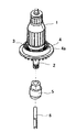
図1は本発明携帯用電気ルータを構成するモータの回転部を示すもので、電機子コイル、電機子コア及び整流子等から構成される電機子1と、電機子軸2と、電機子軸2に取付けられた冷却ラジアルファン3と、電機子軸2の下端のネジ部とネジ結合するチャック5と、チャック5を介して電機子軸2に装着される刃物6が表されている。
【0014】
モータが駆動することにより電機子軸2と共に刃物6が回転し、刃物6によって木材等の面取り加工、溝切り加工等を行うことができるようになる。
【0015】
図2は、上記したモータを採用した本発明携帯用電気ルータの一実施形態を示す部分断面正面図である。
【0016】
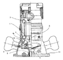
図に示すように、携帯用電気ルータは、木材等の被削材上をスライドする際の案内となるベース11と、ベース11上にベース11に対して図示しない機構により上下動可能に支持された筒状のハウジング12と、ハウジング12内に収納されたモータと、モータ軸である電機子軸2の下端に取付けられるチャック5とを有する構成をしている。
【0017】
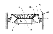
図3は図1に示すラジアルファンと図2に示すハウジング内壁との関係を示す要部拡大断面図であるが、図に示すようにラジアルファン3は、電機子軸2への取り付け部分となる筒状のハブ9と、ハブ9に一部が連結された複数の羽根10と、すべての羽根10の一部と連結され、リング状をしたガイド部4とを有する形状をしている。ガイド部4は羽根10を介してハブ9と連結され、羽根10のハブ9との連結部分とほぼ対向する位置で羽根10と連結されており、ガイド部4はハブ9とは直接的に連結されない形状をしている。各羽根10は電機子軸2の中心軸8を中心とした放射方向に延びた形状をしており、ハブ9よりも半径方向外側に突出する形状をしている。
【0018】
図1及び図3に示すようにガイド部4には、羽根10よりも半径方向外側に突出する錘部4aが連結して設けられている。この錘部4aは、電機子軸2の中心軸8から最も半径方向外側に位置している。
【0019】
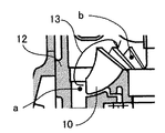
図6は従来のガイド部を有さないラジアルファンを採用した携帯用電気ルータの一例を示した要部拡大図であるが、このようにガイド部を有さないラジアルファンの場合、ファンの回転により圧力が高くなる個所aと圧力が低くなる個所bが発生し、羽根10の範囲外において矢印13に示すようにファン風が流動してしまい、有効な風量を得ることができないものである。
【0020】
このように圧力が高くなる個所から圧力が低くなる個所へとファン風が流動してしまうことを抑制するために、従来羽根10の排出側とモータとの間を遮蔽するファンガイドが設けられているものであるが、本発明ではすべての羽根10の一部と連結しリング状をしたガイド部4がハブ9に対向する位置に設けられており、また羽根10よりも半径方向外側に突出したリング状の錘部4aがガイド部4と連結して設けられている。錘部4aの外周寸法はハウジング12内壁の内周寸法よりも若干小さい大きさに設計されており、これによってラジアルファン3とハウジング12内壁との隙間18が小さくなる。
【0021】
このガイド部4及び錘部4aがファンガイドの機能を兼ねることとなり、上述したように圧力が高くなる個所から圧力が低くなる個所へとファン風が流動してしまうことを抑制することができ、有効な風量を得ることができるようになる。
【0022】
また、錘部4aによって冷却ファンひいてはモータ軸全体の慣性モーメントを大きくすることができ、切削効率を向上させることができるようになる。
【0023】
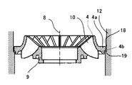
図4は本発明携帯用電気ルータの他の実施形態を示すものであるが、上記実施形態のラジアルファン3とハウジング12内壁の形状を一部変更したものである。
【0024】
図4に示すように錘部4a外周及び錘部4a外周に相対するハウジング12内壁部分にそれぞれ対応する段差部4b及び段差部19を設けたものである。このような構成とすることにより、ラジアルファン3とハウジング12内壁との間の隙間18を段形状とすることができ、ラジアルファン3から見て、ファン風の排出側である図示下方部分から流入側である図示上方部分(モータ側)へファン風が流動する際の流路抵抗を大きくすることができ、ファン風の排出効率を向上させるようにしている。
【0025】
上記実施形態のラジアルファン3は電機子軸2に圧入されることにより取付けられるものであるが、図3に示すハブ9の内壁部分9aが電機子軸2に対する取付部分となる。図3に示すようにラジアルファン3全体の重心位置14が、この電機子軸2の中心軸8方向において内壁部分9aの範囲内に位置する構成となっており、このような構成とすることによって切削作業中に生じる衝撃等によってファン自身が振動し、騒音が発生することを抑制することができるようになる。すなわち、重心位置が電機子軸2に対する取付部分と軸方向でずれた部分にある場合には、衝撃等によってファンが振動してしまい、この振動によって騒音が発生してしまうものであるが、本実施形態のファンによればこれを効果的に抑制することができるようになるものである。
【0026】
また、錘部4aの重心位置も電機子軸2の中心軸8方向において内壁部分9aの範囲内に位置する構成となっており、更に振動を抑制することができるようにしている。
【0027】
なお、上記実施形態のラジアルファン3はアルミニウム等の高比重材によって形成されており、樹脂等に比べ、重量を大きくすることができるため、慣性モーメントを大きく設定することができ、切削効率をより向上させることができるようになる。また、強度を向上させることができ、錘部4aの重量を適正に設定することが可能となるものである。
【0028】
なお、上記実施形態のラジアルファン3は型成形によって形成されるものであり、このため、電機子軸2の中心軸8の方向から型を抜くことができるように、ハブ9の半径方向外側部分よりもガイド部4の半径方向内側部分の方が半径方向外側に位置する形状となっている。
【0029】
図5に本発明携帯用電機ルータを構成するラジアルファンの他の実施形態を示すが、本実施形態のラジアルファン3は、羽根10が、モータ回転軸8の放射方向16に対し、回転方向17と逆方向に傾斜しているものである。これにより、羽根10間を通過する空気流速が羽根10の回転速度より遅くなり、更に低騒音化を図ることができるものである。
【0030】
【発明の効果】
以上のように本発明によれば、モータ軸への取付け部分となる筒形状をしたハブと、ハブに一部が連結した複数の羽根と、すべての羽根の一部と連結されリング状をし、ハブと羽根を介して連結されたガイドとを有する形状をしたラジアルファンのガイドに羽根よりもモータ軸を中心とした半径方向外側に突出した錘部を連結させたことによって、流体騒音を低下させ、切削能率を向上させることができ、更に、ファンガイドといった別部品を排除し低コスト化を図ることができる携帯用電機ルータを提供することができるようになる。
【図面の簡単な説明】
【図1】本発明携帯用電気ルータを構成するモータの一実施形態を示す展開図。
【図2】本発明携帯用電機ルータの一実施形態を示す要部断面正面図。
【図3】本発明携帯用電機ルータの一実施形態を構成するラジアルファン及びハウジング内壁の関係を示す要部拡大断面図。
【図4】本発明携帯用電機ルータの他の実施形態を構成するラジアルファン及びハウジング内壁の関係を示す要部拡大断面図。
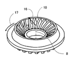
【図5】本発明携帯用電気ルータを構成するラジアルファンの他の実施形態を示す斜視図。
【図6】従来の携帯用電機ルータの一例を示す要部拡大断面図。
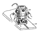
【図7】携帯用電気ルータの一例を示す斜視図。
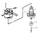
【図8】従来のモータの一例を示す展開図。
【符号の説明】
1は電機子、2は電機子軸、3は冷却ファン、4はガイド部、4aは錘部、5はチャック、6は刃物、7は固定子、9はハブである。[0001]
[Industrial applications]
The present invention relates to a portable electric tool (hereinafter, referred to as a portable electric router) such as a portable electric router that mounts a blade on a motor shaft and rotates the blade to perform chamfering, grooving, and the like. .
[0002]
[Prior art]
FIG. 7 shows an example of a conventional portable electric router.
[0003]
As is well known, the electric router includes a
[0004]
FIG. 8 is an exploded view showing an example of a conventional motor. The motor includes a
[0005]
Japanese Patent Application Laid-Open No. Hei 6-218703 discloses that, by connecting the outer peripheral ends of the blades of a cooling
[Patent Document 1]
JP-A-6-218703
[Problems to be solved by the invention]
The portable electric router configured as described above is a tool for chamfering and grooving wood and the like, and is an essential tool especially for manufacturing furniture and the like. The basic performance required for this kind of tool is good cutting efficiency, light weight and good operability, and good surface finish. If the finishing performance for commercialization is obtained among these basic performances, it is usually required firstly that the cutting efficiency is good in terms of productivity improvement.
[0007]
Therefore, a generally employed means for improving the cutting efficiency is to increase the thickness of the motor, that is, to increase the size of the motor and increase the rotational force of the motor. However, increasing the size of the motor increases the weight of the entire tool, and increases the cores, coils, and the like of the
[0008]
In addition, if the technique disclosed in Japanese Patent Application Laid-Open No. 6-218703 is adopted, the cutting efficiency can be improved without increasing the size of the motor. When used for cooling passing through a flow path, the efficiency is generally poor and noise is increased. The noise was particularly large during no-load operation.
[0009]
When a radial fan is used as a cooling fan, noise is less generated than an axial fan.However, a fan guide is used to guide cooling air so that cooling air is not discharged to the motor side. It is necessary to provide between the motor and the discharge side of the blade, so that the number of parts increases, the assemblability decreases, and the cost increases.
[0010]
SUMMARY OF THE INVENTION An object of the present invention is to provide a portable electric router which solves the above-mentioned drawbacks, suppresses noise generation, has a small number of parts, has good assemblability, is low in cost, and can improve cutting efficiency. That is.
[0011]
[Means for Solving the Problems]
The object is to provide a hub having a cylindrical shape to be attached to a motor shaft, a plurality of blades partially connected to the hub, a ring shape connected to a portion of all the blades, and a hub through the blades. This is achieved by connecting a weight portion protruding radially outward around the motor shaft from the blades to the guide of the radial fan having a shape connected to the radial fan.
[Action]
With the above-described configuration, the cooling fan and, consequently, the moment of inertia of the entire motor shaft is increased, so that not only the cutting efficiency can be improved even with the same motor, but also the radial fan allows passage through a narrow passage. Even when used for cooling, the noise does not increase, and the center of gravity of the weight is located within the interference position of the fan, so that the vibration of the fan can be reduced and noise during cutting is generated. Never. Further, since the guide portion and the weight portion also serve as the fan guide, the number of components does not increase, and the cost is also advantageous.
[0012]
BEST MODE FOR CARRYING OUT THE INVENTION
The portable electric router of the present invention will be described with reference to FIGS.
[0013]
FIG. 1 shows a rotating portion of a motor constituting a portable electric router according to the present invention. The armature 1 includes an armature coil, an armature core, a commutator, and the like, an
[0014]
When the motor is driven, the
[0015]
FIG. 2 is a partial sectional front view showing an embodiment of the portable electric router of the present invention employing the above-described motor.
[0016]
As shown in the figure, the portable electric router is supported on a
[0017]
FIG. 3 is an enlarged sectional view of a main part showing the relationship between the radial fan shown in FIG. 1 and the inner wall of the housing shown in FIG. 2. As shown in the figure, the
[0018]
As shown in FIGS. 1 and 3, the
[0019]
FIG. 6 is an enlarged view of a main portion showing an example of a conventional portable electric router employing a radial fan having no guide portion. In the case of a radial fan having no guide portion, the fan rotates. As a result, a point a where the pressure is increased and a point b where the pressure is decreased are generated, and the fan wind flows outside the range of the
[0020]
In order to prevent the fan wind from flowing from the location where the pressure becomes high to the location where the pressure becomes low, a fan guide that shields between the discharge side of the
[0021]
The
[0022]
In addition, the
[0023]
FIG. 4 shows another embodiment of the portable electric router of the present invention, in which the shapes of the
[0024]
As shown in FIG. 4, a
[0025]
The
[0026]
Further, the position of the center of gravity of the
[0027]
The
[0028]
Note that the
[0029]
FIG. 5 shows another embodiment of the radial fan constituting the portable electric router of the present invention. In the
[0030]
【The invention's effect】
As described above, according to the present invention, a cylindrical hub serving as a mounting portion to a motor shaft, a plurality of blades partially connected to the hub, and a ring-shaped The fluid noise is reduced by connecting a weight that protrudes radially outward around the motor shaft from the blade to the guide of the radial fan, which has a hub and a guide connected via a blade. As a result, it is possible to provide a portable electric router capable of improving cutting efficiency and eliminating a separate component such as a fan guide to reduce costs.
[Brief description of the drawings]
FIG. 1 is a development view showing an embodiment of a motor constituting a portable electric router of the present invention.
FIG. 2 is a sectional front view of a main part showing one embodiment of the portable electric router of the present invention.
FIG. 3 is an enlarged sectional view of a main part showing a relationship between a radial fan and an inner wall of a housing which constitute one embodiment of the portable electric router of the present invention.
FIG. 4 is an essential part enlarged sectional view showing the relationship between a radial fan and a housing inner wall which constitute another embodiment of the portable electric router of the present invention.
FIG. 5 is a perspective view showing another embodiment of the radial fan constituting the portable electric router of the present invention.
FIG. 6 is an enlarged sectional view of a main part showing an example of a conventional portable electric router.
FIG. 7 is a perspective view showing an example of a portable electric router.
FIG. 8 is a development view showing an example of a conventional motor.
[Explanation of symbols]
1 is an armature, 2 is an armature shaft, 3 is a cooling fan, 4 is a guide portion, 4a is a weight portion, 5 is a chuck, 6 is a blade, 7 is a stator, and 9 is a hub.
Claims (8)
前記ラジアルファンは、前記モータ軸への取付け部分となる筒形状をしたハブと、該ハブに一部が連結した複数の羽根と、すべての該羽根の一部と連結されリング状をし、前記羽根を介して前記ハブと連結されたガイド部とを有する形状をし、且つ前記ガイド部に前記羽根よりも前記モータ軸を中心とした半径方向外側に突出した錘部を連結させたことを特徴とする携帯用電気ルータ。A portable power tool having a motor, a housing for housing the motor, and a radial fan attached to a motor shaft of the motor,
The radial fan has a cylindrical hub serving as a portion to be attached to the motor shaft, a plurality of blades partially connected to the hub, and a ring connected to a part of all the blades. A guide portion connected to the hub via a blade, and a weight portion protruding radially outward with respect to the motor shaft from the blade relative to the blade is connected to the guide portion. And portable electric router.
Priority Applications (4)
| Application Number | Priority Date | Filing Date | Title |
|---|---|---|---|
| JP2003136553A JP4407158B2 (en) | 2003-05-14 | 2003-05-14 | Portable power tools |
| US10/845,077 US7171997B2 (en) | 2003-05-14 | 2004-05-14 | Portable electric router having radial fan |
| GB0410757A GB2401576B (en) | 2003-05-14 | 2004-05-14 | Portable electric router having radial fan |
| GB0610880A GB2423956B (en) | 2003-05-14 | 2004-05-14 | Portable electric router having radial fan |
Applications Claiming Priority (1)
| Application Number | Priority Date | Filing Date | Title |
|---|---|---|---|
| JP2003136553A JP4407158B2 (en) | 2003-05-14 | 2003-05-14 | Portable power tools |
Publications (3)
| Publication Number | Publication Date |
|---|---|
| JP2004338192A true JP2004338192A (en) | 2004-12-02 |
| JP2004338192A5 JP2004338192A5 (en) | 2006-04-20 |
| JP4407158B2 JP4407158B2 (en) | 2010-02-03 |
Family
ID=32588729
Family Applications (1)
| Application Number | Title | Priority Date | Filing Date |
|---|---|---|---|
| JP2003136553A Expired - Lifetime JP4407158B2 (en) | 2003-05-14 | 2003-05-14 | Portable power tools |
Country Status (3)
| Country | Link |
|---|---|
| US (1) | US7171997B2 (en) |
| JP (1) | JP4407158B2 (en) |
| GB (2) | GB2401576B (en) |
Cited By (3)
| Publication number | Priority date | Publication date | Assignee | Title |
|---|---|---|---|---|
| JP2012528013A (en) * | 2009-05-27 | 2012-11-12 | ローベルト ボツシユ ゲゼルシヤフト ミツト ベシユレンクテル ハフツング | Machine Tools |
| JPWO2022091966A1 (en) * | 2020-10-30 | 2022-05-05 | ||
| CN114603662A (en) * | 2022-04-26 | 2022-06-10 | 丰县泰宏全屋定制有限公司 | Wood system stair are stand kerve device for automated production |
Families Citing this family (17)
| Publication number | Priority date | Publication date | Assignee | Title |
|---|---|---|---|---|
| USD546654S1 (en) * | 2004-01-29 | 2007-07-17 | Black & Decker Inc. | Router with plunge base |
| DE102008001258A1 (en) * | 2008-04-18 | 2009-10-22 | Robert Bosch Gmbh | Machine tool with electric drive motor |
| WO2009134885A1 (en) | 2008-04-29 | 2009-11-05 | Ivus Industries, Inc. | Wide voltage, high efficiency led driver circuit |
| US20100038405A1 (en) * | 2008-08-13 | 2010-02-18 | Garner Timothy D | Spindle-integrated cooling and collection device for stir friction welder |
| DE102008059599A1 (en) * | 2008-11-28 | 2010-06-02 | Aeg Electric Tools Gmbh | power tool |
| DE102012201593A1 (en) * | 2012-02-03 | 2013-08-08 | Robert Bosch Gmbh | Hand machine tool device |
| US9156153B2 (en) * | 2012-07-19 | 2015-10-13 | Robert Bosch Gmbh | Collet fan for a rotary tool |
| JP6277634B2 (en) * | 2013-08-30 | 2018-02-14 | 日立工機株式会社 | Portable cutting machine |
| CN105387130B (en) * | 2015-12-04 | 2017-06-30 | 浙江锋龙电气股份有限公司 | For the flywheel of engine |
| CN105546035A (en) * | 2016-03-28 | 2016-05-04 | 茹咪娜 | Durable magnetic flywheel |
| US20170341115A1 (en) * | 2016-04-15 | 2017-11-30 | Wesley Ross Noll | Machine Tool Accessory for Swarf Removal |
| DE102018108762A1 (en) * | 2018-04-12 | 2019-10-17 | Gühring KG | Suction device with blades as well as the production process intended for this purpose |
| WO2019204056A1 (en) | 2018-04-16 | 2019-10-24 | Milwaukee Electric Tool Corporation | Inertial fan for power tool |
| EP3690229B8 (en) | 2019-01-31 | 2021-11-24 | Danfoss Power Solutions II Technology A/S | Displacement control with angle sensor adjustment |
| CN114641383A (en) * | 2019-10-31 | 2022-06-17 | 工机控股株式会社 | Router |
| EP4228841A4 (en) | 2020-10-14 | 2025-06-18 | Milwaukee Electric Tool Corporation | HANDHELD PUNCHING TOOL |
| WO2023119329A1 (en) * | 2021-12-22 | 2023-06-29 | National Institute of Technology Tiruchirappalli | Forced cooling friction stir welding tool and method thereof |
Family Cites Families (11)
| Publication number | Priority date | Publication date | Assignee | Title |
|---|---|---|---|---|
| US4360751A (en) * | 1980-06-06 | 1982-11-23 | Kollmorgen Technologies Corporation | Fan with integral disc-shaped drive |
| US4459087A (en) * | 1982-06-02 | 1984-07-10 | Aciers Et Outillage Peugeot | Fan unit for an internal combustion engine of automobile vehicle |
| US4564780A (en) * | 1983-03-14 | 1986-01-14 | Eastway Holdings Limited | Electrical machine having a quickly releasable stator |
| JPS62221839A (en) * | 1986-03-20 | 1987-09-29 | Hitachi Ltd | Ac generator for motor car |
| US4836155A (en) * | 1988-01-11 | 1989-06-06 | Slagley Michael W | Variable duration valve opening mechanism |
| US4836755A (en) * | 1988-03-22 | 1989-06-06 | Durr Dental Gmbh & Co Kg | Compressor with balanced flywheel |
| DE4003029A1 (en) * | 1990-02-02 | 1991-08-08 | Bosch Gmbh Robert | HANDMADE MACHINE TOOL WITH A RADIAL BLOWER |
| JPH06218703A (en) * | 1993-01-22 | 1994-08-09 | Hitachi Koki Co Ltd | Portable electric router |
| US5632578A (en) * | 1996-02-23 | 1997-05-27 | Ryobi North America | Exhaust stator and fan for a power tool |
| US6411000B1 (en) * | 1999-11-02 | 2002-06-25 | Lg Electronics Inc. | Motor with a cooling means |
| US20040035495A1 (en) * | 2002-08-21 | 2004-02-26 | Hessenberger Jeffrey C. | Router |
-
2003
- 2003-05-14 JP JP2003136553A patent/JP4407158B2/en not_active Expired - Lifetime
-
2004
- 2004-05-14 GB GB0410757A patent/GB2401576B/en not_active Expired - Fee Related
- 2004-05-14 US US10/845,077 patent/US7171997B2/en not_active Expired - Lifetime
- 2004-05-14 GB GB0610880A patent/GB2423956B/en not_active Expired - Lifetime
Cited By (6)
| Publication number | Priority date | Publication date | Assignee | Title |
|---|---|---|---|---|
| JP2012528013A (en) * | 2009-05-27 | 2012-11-12 | ローベルト ボツシユ ゲゼルシヤフト ミツト ベシユレンクテル ハフツング | Machine Tools |
| US9399275B2 (en) | 2009-05-27 | 2016-07-26 | Robert Bosch Gmbh | Machine tool, in particular hand machine tool |
| JPWO2022091966A1 (en) * | 2020-10-30 | 2022-05-05 | ||
| JP7494937B2 (en) | 2020-10-30 | 2024-06-04 | 工機ホールディングス株式会社 | Work Machine |
| CN114603662A (en) * | 2022-04-26 | 2022-06-10 | 丰县泰宏全屋定制有限公司 | Wood system stair are stand kerve device for automated production |
| CN114603662B (en) * | 2022-04-26 | 2022-09-23 | 丰县泰宏全屋定制有限公司 | Wood system stair are stand draw groove device for automated production |
Also Published As
| Publication number | Publication date |
|---|---|
| JP4407158B2 (en) | 2010-02-03 |
| GB2423956B (en) | 2006-11-15 |
| GB2401576B (en) | 2006-11-15 |
| GB0410757D0 (en) | 2004-06-16 |
| GB2423956A (en) | 2006-09-13 |
| GB2401576A (en) | 2004-11-17 |
| US20040250890A1 (en) | 2004-12-16 |
| US7171997B2 (en) | 2007-02-06 |
| GB0610880D0 (en) | 2006-07-12 |
Similar Documents
| Publication | Publication Date | Title |
|---|---|---|
| JP4407158B2 (en) | Portable power tools | |
| EP3074177B1 (en) | Sander having two-piece fan | |
| US5375637A (en) | Portable electric router | |
| JP5019126B2 (en) | Electric tool | |
| CN107030608B (en) | sander | |
| CN107110171B (en) | Electric blower and electric vacuum cleaner equipped with it | |
| CN210290212U (en) | Fan and electrical equipment | |
| JP6333771B2 (en) | Spindle structure, electric motor, and machine tool having through holes for fluid flow | |
| US20060250033A1 (en) | Rotating electrical machine comprising a ventilator | |
| CN110999032B (en) | Rotor and motor comprising same | |
| JP2016153636A (en) | Electric blower and vacuum cleaner | |
| KR20150037494A (en) | Scroll type fluid machine | |
| CN109276183A (en) | Air supply device and dust catcher | |
| CN1232735C (en) | Forced draught blower | |
| CN110994905B (en) | A noise reduction motor | |
| JPWO2020251041A5 (en) | ||
| JP2020096530A (en) | Electric blower and vacuum cleaner | |
| US12134177B2 (en) | Power tool | |
| JP2018145897A (en) | Electric blower and vacuum cleaner including the same | |
| CN114135502A (en) | Rotating device | |
| CN214590972U (en) | External rotor motor and electric tool | |
| JP2016158402A (en) | Electric blower and vacuum cleaner | |
| JP2018191509A (en) | Electric blower and vacuum cleaner | |
| JP2018001284A (en) | Electric power tool | |
| JP6690603B2 (en) | Centrifugal blower |
Legal Events
| Date | Code | Title | Description |
|---|---|---|---|
| A521 | Request for written amendment filed |
Free format text: JAPANESE INTERMEDIATE CODE: A523 Effective date: 20060303 |
|
| A621 | Written request for application examination |
Free format text: JAPANESE INTERMEDIATE CODE: A621 Effective date: 20060303 |
|
| A977 | Report on retrieval |
Free format text: JAPANESE INTERMEDIATE CODE: A971007 Effective date: 20080519 |
|
| A131 | Notification of reasons for refusal |
Free format text: JAPANESE INTERMEDIATE CODE: A131 Effective date: 20090728 |
|
| A521 | Request for written amendment filed |
Free format text: JAPANESE INTERMEDIATE CODE: A523 Effective date: 20090928 |
|
| TRDD | Decision of grant or rejection written | ||
| A01 | Written decision to grant a patent or to grant a registration (utility model) |
Free format text: JAPANESE INTERMEDIATE CODE: A01 Effective date: 20091020 |
|
| A01 | Written decision to grant a patent or to grant a registration (utility model) |
Free format text: JAPANESE INTERMEDIATE CODE: A01 |
|
| A61 | First payment of annual fees (during grant procedure) |
Free format text: JAPANESE INTERMEDIATE CODE: A61 Effective date: 20091102 |
|
| R150 | Certificate of patent or registration of utility model |
Ref document number: 4407158 Country of ref document: JP Free format text: JAPANESE INTERMEDIATE CODE: R150 Free format text: JAPANESE INTERMEDIATE CODE: R150 |
|
| FPAY | Renewal fee payment (event date is renewal date of database) |
Free format text: PAYMENT UNTIL: 20121120 Year of fee payment: 3 |
|
| FPAY | Renewal fee payment (event date is renewal date of database) |
Free format text: PAYMENT UNTIL: 20121120 Year of fee payment: 3 |
|
| FPAY | Renewal fee payment (event date is renewal date of database) |
Free format text: PAYMENT UNTIL: 20131120 Year of fee payment: 4 |
|
| FPAY | Renewal fee payment (event date is renewal date of database) |
Free format text: PAYMENT UNTIL: 20141120 Year of fee payment: 5 |
|
| S533 | Written request for registration of change of name |
Free format text: JAPANESE INTERMEDIATE CODE: R313533 |
|
| R350 | Written notification of registration of transfer |
Free format text: JAPANESE INTERMEDIATE CODE: R350 |
|
| EXPY | Cancellation because of completion of term |