【0001】
【発明の属する技術分野】本発明は、記録装置、特にインクヘッドを装着したキャリアがガイドシャフトに案内されて往復走行するようになっている記録装置に関する。
【0002】
【従来の技術】インクジェットプリンタなどの記録装置において、インクヘッドを装着したキャリアがガイドシャフトに案内されて往復走行するようになっているものでは、キャリアに設けられている軸受部が潤滑用グリスを塗布したガイドシャフトに摺動自在に嵌合されている。
【0003】従来のこの種記録装置では、断面視円形のガイドシャフトに、内面が円形面に形成されている軸受部が摺動自在に嵌合されているため、キャリアが前記ガイドシャフトに案内されて一定領域を往復走行するという動作が繰り返されると、ガイドシャフトに塗布されていた潤滑用グリスの余剰分(余剰グリス)が軸受部によって前記領域の端部に押しやられたままになる。その反面、前記領域内では、ガイドシャフト表面と軸受部の内面との間の微細な隙間(クリアランス)にグリスが膜状に残るが、その隙間内にグリスが補給されることはない。この結果、前記グリスの乾燥が促進されて潤滑性が徐々に低下し、キャリアの異常動作を起こしたり、場合によってはキャリアの動作が停止してしまうといった事態が生じるなどといった、不都合がある。
【0004】ところで、上述の点を考慮して、例えばインクヘッド着脱部とそのインクヘッド着脱部の背部に一体に設けられた合成樹脂製の軸受部とを一体に有するキャリアの前記軸受部が潤滑用グリスを塗布した断面視円形のガイドシャフトに摺動自在に嵌合され、前記軸受部の内面がその内面を軸方向に横切る溝部を周方向等間隔おきの複数箇所に有していると共に、前記溝部とガイドシャフトとの間に、余剰グリスが寄り集まることのできる隙間が形成され、かつ、これらの隙間は前記ガイドシャフトの外周面の頂部を除く箇所に形成したものが別途本件出願人によって提案されている(例えば、特許文献1参照)。
【0005】
【特許文献1】
特開平2002−172827号公報
【0006】
【発明が解決しようとする課題】前述の特許文献1記載の構成では、従来のように、オイルバッドなどの余分な部材を用いずに、ガイドシャフトと軸受部との摺動箇所への潤滑用グリスの補給が可能となり、キャリアの走行安定性の向上によって印字品質などが常に良好に保たれるようになり、また、軸受部とガイドシャフトとの摺動によって発生する摩耗粉に起因してキャリアの走行安定性が損なわれるという事態も抑制され都合がよい。ところが、前記ガイドシャフトと軸受部の内面との接触部分は、前記溝部が形成された以外は、略面的接触であることから、摩擦面積が多く、高負荷となり、特に低温での使用時、キャリア動作負荷上昇に伴って、印字ピッチ不良(縦縞)が発生し、ときには印字動作が停止することがある。さらには、前記溝部から補給される潤滑用グリスには限りがあり、自ずと使用期間が限られるなどといった課題がある。
【0007】本発明は、上述した問題を解決するためになされたものであり、極めて簡単な構成により、ガイドシャフトと軸受部の内面との摩擦面積を効果的に減少し、キャリア動作に対する負荷を低減し、低温での使用を可能にするとともに、より長期間に亘って使用できるようにした記録装置を提供することを目的とする。
【0008】
【課題を解決するための手段】かかる目的を達成するため、請求項1記載の発明では、インクヘッドが装着されるインクヘッド着脱部の背部に一体に設けられた合成樹脂製の軸受部を有するキャリアと、潤滑用グリスを塗布した断面視円形のガイドシャフトとを備え、このガイドシャフトに前記キャリアの軸受部を摺動自在に嵌合してなる記録装置において、前記軸受部の内面を、前記ガイドシャフトとの接触が上部円弧側ではその軸方向で少なくとも2箇所以上点または線的接触に、下部円弧側ではその軸方向で面的接触とし、かつ、前記面的接触部分には内面を軸方向に横切る溝部を少なくとも二条以上形成し、これらガイドシャフトと軸受部との間に形成される隙間に、前記潤滑用グリスが保持されるように構成する。
【0009】請求項1記載の発明の構成によれば、相対的に負荷の掛かりが少ない上部円弧側ではその軸方向で少なくとも2箇所以上点または線的接触とし、相対的に負荷の掛かりが多い下部円弧側ではその軸方向で面的接触とし、この面的接触部分には内面を軸方向に横切る溝部を少なくとも二条以上形成してこれらガイドシャフトと軸受部との間に形成される隙間に、前記潤滑用グリスを保持するように構成しているので、摩擦面積は略半減するとともに、キャリアの走行によってガイドシャフトを軸受部が摺動すると、その軸受部の内面とガイドシャフトとの間に形成される隙間の走行跡に、余剰グリスが寄り集まって大きなグリスラインが形成される。このため、従来のようにキャリア走行領域の端部に余剰グリスが押しやられてしまうという現象が抑制される。また、前記グリスラインを形成している大量の潤滑用グリスは、その後に軸受部がガイドシャフトを摺動したときに、軸受部の内面とガイドシャフトとの摺動箇所に少しずつ給送されてガイドシャフトの表面に膜状に残っているグリスの乾燥を防ぐ。従がって、キャリアの走行時には、摩擦面積が略半減したこと、およびグリスラインからの前記摺動箇所へのグリス補給と、余剰グリスのグリスラインへの寄り集まりとが相伴って、低温での使用が可能となる他、キャリア走行安定性は、グリス溜まりが増大したことにより、長期間に亘って良好に維持されるようになる。しかも、そのための構成は極めて簡単で、軸受部を合成樹脂で成形する際に一体に形成すればよく、殊更オイルバッドなどの余分な部材を用いる必要がなくなるので、部品点数を増やさずにキャリア走行安定性を高めることが可能となる。
【0010】請求項2記載の発明では、インクヘッド着脱部を有するキャリアの軸受部が潤滑用グリスを塗布したガイドシャフトに摺動自在に嵌合され、前記軸受部と上記ガイドシャフトとの間に、前記潤滑用グリスが保持できる隙間が、前記軸受部の内面を軸方向に横切る形態で形成された記録装置において、前記ガイドシャフトと軸受部との接触に際し、相対的に負荷の掛かりが少ない円弧側部分ではその軸方向で点または線的接触とし、これらガイドシャフトと軸受部との間に前記潤滑用グリスを保持する隙間を形成するとともに、相対的に負荷の掛かりが多い他の円弧側部分ではその軸方向で面的接触に構成する。
【0011】請求項2記載の発明の構成によれば、相対的に負荷の掛かりが少ない円弧側ではその軸方向で点または線的接触とし、相対的に負荷の掛かりが多い他の円弧側ではその軸方向で面的接触とし、これらガイドシャフトと軸受部との間に形成される隙間に、前記潤滑用グリスを保持するように構成しているので、摩擦面積は略半減し、キャリアの走行によってガイドシャフトを軸受部が摺動すると、その軸受部の内面とガイドシャフトとの間に形成される隙間の走行跡に、余剰グリスが寄り集まって大きなグリスラインが形成される。このため、従来のようにキャリア走行領域の端部に余剰グリスが押しやられてしまうという現象が抑制される。また、前記グリスラインを形成している大量の潤滑用グリスは、その後に軸受部がガイドシャフトを摺動したときに、軸受部の内面とガイドシャフトとの摺動箇所に少しずつ給送されてガイドシャフトの表面に膜状に残っているグリスの乾燥を防ぐ。従がって、キャリアの走行時には、摩擦面積が減じたこと、およびグリスラインからの前記摺動箇所へのグリス補給と、余剰グリスのグリスラインへの寄り集まりとが相伴って、低温での使用が可能となる他、キャリア走行安定性は、グリス溜まりが増大したことにより、長期間に亘って良好に維持されるようになる。しかも、そのための構成は極めて簡単で、軸受部を合成樹脂で成形する際に一体に形成すればよく、殊更オイルバッドなどの余分な部材を用いる必要がなくなるので、部品点数を増やさずにキャリア走行安定性を高めることが可能となる。
【0012】請求項3記載の発明では、インクヘッドが装着されるインクヘッド着脱部の背部に一体に設けられた合成樹脂製の軸受部を有するキャリアと、潤滑用グリスを塗布した断面視円形のガイドシャフトとを備え、このガイドシャフトに前記キャリアの軸受部を摺動自在に嵌合してなる記録装置において、前記軸受部の内面を、前記ガイドシャフトとの接触が上部円弧側ではその軸方向で点または線的接触に、下部円弧側ではその軸方向で面的接触とし、かつ、前記点または線的接触は、少なくともガイドシャフトの頂部を含むとともに、前記面的接触部分には内面を軸方向に横切る溝部を少なくとも一条以上形成し、これらガイドシャフトと軸受部との間に形成される隙間に、前記潤滑用グリスが保持されるように構成する。
【0013】請求項3記載の発明の構成によっても上部円弧側ではその軸方向で少なくとも頂部を含んで点または線的接触とし、下部円弧側ではその軸方向で面的接触とし、この面的接触部分には内面を軸方向に横切る溝部を少なくとも一条以上形成し、摩擦面積を略半減しするとともに、ガイドシャフトと軸受部との間に形成される隙間に、前記潤滑用グリスを保持するように構成しているので、上述したものと同様の作用効果を奏する。
【0014】請求項4記載の発明では、前記点または線的接触は、少なくともガイドシャフトの頂部と、この頂部から左右略45度の位置にそれぞれ配設する。
【0015】請求項4記載の発明の構成によれば、上述したものと同様の作用効果を奏する他、前記点または線的接触は、少なくともガイドシャフトの頂部と、この頂部から左右略45度の位置にそれぞれ配設さ、ガイドシャフトの上部円弧側の等角度に形成されるので、バランスよく負荷が掛かり、キャリア走行安定性がより良好に維持されるようになり、都合がよい。
【0016】請求項5記載の発明では、前記面的接触部分の内面を軸方向に横切る溝部は、少なくともガイドシャフトの底部と、この底部から左右略45度の位置にそれぞれ配設する。
【0017】請求項5記載の発明の構成によれば、上述したものと同様の作用効果を奏する他、前記面的接触部分の内面を軸方向に横切る溝部は、少なくともガイドシャフトの底部と、この底部から左右略45度の位置にそれぞれ配設され、ガイドシャフトの下部円弧側の等角度に形成されるので、前記したグリスラインからの前記摺動箇所へのグリス補給と、余剰グリスのグリスラインへの寄り集まりとがガイドシャフトの周方向で万遍なく長期間に亘り行われてキャリア走行安定性が常に良好に維持されるようになる。
【0018】
【発明の実施の形態】以下、本発明の一実施形態を図1乃至図3に基づき説明する。
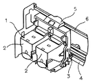
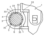
【0019】図1は、本発明の一実施形態による記録装置の概略構成を示す斜視図、図2は、図1に示す記録装置の要部を拡大して示す縦断面拡大図、図3は、図1に示す記録装置のキャリアの軸受部とガイドシャフトとの関係を示す部分断面図である。
【0020】1は、キャリアで、インクヘッド着脱部2とそのインクヘッド着脱部2の背部に一体に設けられた合成樹脂製の軸受部3とを一体に有する。前記インクヘッド着脱部2には、図示しないがそれぞれ黒色およびカラー用のインクヘッドが装着されている。前記軸受部3は、潤滑用グリスを塗布した断面視円形のガイドシャフト4に摺動自在に嵌合されている。前記キャリア1には、その上部に摺動部5を備えており、この摺動部5が、シャーシなどによって形成された水平なレール部6によって案内されるようになっている。
【0021】前記合成樹脂製の軸受部3の内面31は、その内面31が前記ガイドシャフト4との接触に際し、相対的に負荷の掛かりが少ない上部円弧32側部分は、その軸方向で線的接触となるように、この例では、上部円弧32の頂部Tに突起部33が連続的に形成されている。この場合、前記軸受部3の内面31の軸方向に突起部33を複数個適当な間隔を空けて設け、点接触となるようにしてもよいのは勿論である。また、相対的に負荷の掛かりが多い他の円弧側すなわち、下部円弧34側部分は、その軸方向で面的接触となるように形成されている。この例では、前記下部円弧34側部分の底部Bに軸方向に横切る溝部35が形成されている。従って、前記突起部33および溝部35の存在により、これらガイドシャフト4と軸受部3の内面31との間に形成される隙間Sに、余剰グリスが寄り集まり、潤滑用グリスが保持されることとなる。前記点または線的接触と面的接触が、軸受部3の内面31のガイドシャフト30の表面に対する摺動部分となっている。なお、図中36は、軸受部31に形成された面取り部で、このような面取り部36を形成しておくと軸受部3をガイドシャフト4に挿入する際に入りやすくなり、都合がよい。
【0022】以上のような実施の形態では、相対的に負荷の掛かりが少ない円弧側である上部円弧32側部分には、その軸方向で線的接触となるように、上部円弧32の頂部Tに突起部33を連続的に形成し、また、相対的に負荷の掛かりが多い他の円弧側である下部円弧34側部分には、その軸方向で面的接触となるようにするとともに、その底部Bに軸方向に横切る溝部35を形成してその摩擦面積を略半減するとともに、これら摩擦面積を略半減し、ガイドシャフト4と軸受部3の内面31との間に形成される隙間Sに、前記潤滑用グリスを保持するように構成しているので、キャリア1の走行によってガイドシャフト4を軸受部3が摺動すると、その軸受部3の内面31とガイドシャフト4との間に形成される隙間Sの走行跡に、余剰グリスが寄り集まって大きなグリスラインが形成される。このため、従来のようにキャリア走行領域の端部に余剰グリスが押しやられてしまうという現象が抑制される。また、前記グリスラインを形成している大量の潤滑用グリスは、その後に軸受部3がガイドシャフト4を摺動したときに、軸受部3の内面31とガイドシャフト4との摺動箇所、特に、負荷の掛かりが多い円弧側である下部円弧34側、すなわち面的接触部分に少しずつ給送されてガイドシャフト4の表面に膜状に残っているグリスの乾燥を防ぐ。従がって、キャリア1の走行時には、摩擦面積が減じたこと、およびグリスラインからの前記摺動箇所へのグリス補給と、余剰グリスのグリスラインへの寄り集まりとが相伴って、低温での使用が可能となる他、キャリア走行安定性は、グリス溜まりが増大したことにより、長期間に亘って良好に維持されるようになる。しかも、そのための構成は極めて簡単で、軸受部3を合成樹脂で成形する際に一体に形成すればよく、殊更オイルバッドなどの余分な部材を用いる必要がなくなるので、部品点数を増やさずにキャリア走行安定性を高めることが可能となる。
【0023】次に、図4に示す本発明の他の実施形態について説明する。なお、図4において図1乃至図3と同じ符号を付した部分は略同一のものを示す。以下相違点を中心に説明する。
【0024】図4は、本発明の他の実施形態による記録装置の要部を拡大して示す縦断面拡大図である。
【0025】この形態では、前記相対的に負荷の掛かりが少ない円弧側である上部円弧32側部分には、その軸方向で点または線的接触となるように形成される突起部33が、少なくともガイドシャフトの頂部Tと、この頂部Tから左右略45度の位置にそれぞれ配設されている。また、相対的に負荷の掛かりが多い他の円弧側で、面的接触になるように形成される下部円弧34側部分には、その軸方向に横切る溝部35が、少なくともガイドシャフト4の底部Bと、この底部Bから左右略45度の位置にそれぞれ配設されている。そして、上述した実施態様と同様、ガイドシャフト4と軸受部3の内面31との間に形成される隙間Sに、前記潤滑用グリスを保持するように構成されている。
【0026】この構成によれば、前述の実施形態と同様の作用効果を奏する他、前記点または線的接触は、少なくともガイドシャフト4の頂部Tと、この頂部Tから左右略45度の位置にそれぞれ配設さ、ガイドシャフト4の上部円弧32側の等角度に形成されるので、バランスよく負荷が掛かり、キャリア走行安定性がより良好に維持されるようになり、都合がよい。また、前記面的接触部分である下部円弧34の内面31を軸方向に横切る溝部35は、少なくともガイドシャフト4の底部Bと、この底部Bから左右略45度の位置にそれぞれ配設され、ガイドシャフト4の下部円弧34側の等角度に形成されるので、前記したグリスラインからの前記摺動箇所へのグリス補給と、余剰グリスのグリスラインへの寄り集まりとがガイドシャフト4の周方向で万遍なく行われてキャリア走行安定性が常に良好に維持されるようになる。
【0027】なお、上述した各実施の形態は、本発明の好適な実施の形態の例であるが、これに限定されるものではなく、本発明の要旨を逸脱しない範囲において、種々変形実施可能である。
【0028】
【発明の効果】以上説明したように、請求項1記載の発明では、相対的に負荷の掛かりが少ない上部円弧側ではその軸方向で少なくとも2箇所以上点または線的接触とし、相対的に負荷の掛かりが多い下部円弧側ではその軸方向で面的接触とし、この面的接触部分には内面を軸方向に横切る溝部を少なくとも二条以上形成してこれらガイドシャフトと軸受部との間に形成される隙間に、前記潤滑用グリスを保持するように構成しているので、摩擦面積は略半減するとともに、キャリアの走行によってガイドシャフトを軸受部が摺動すると、その軸受部の内面とガイドシャフトとの間に形成される隙間の走行跡に、余剰グリスが寄り集まって大きなグリスラインが形成される。このため、従来のようにキャリア走行領域の端部に余剰グリスが押しやられてしまうという現象が抑制される。また、前記グリスラインを形成している大量の潤滑用グリスは、その後に軸受部がガイドシャフトを摺動したときに、軸受部の内面とガイドシャフトとの摺動箇所に少しずつ給送されてガイドシャフトの表面に膜状に残っているグリスの乾燥を防ぐ。従がって、キャリアの走行時には、摩擦面積が略半減したこと、およびグリスラインからの前記摺動箇所へのグリス補給と、余剰グリスのグリスラインへの寄り集まりとが相伴って、低温での使用が可能となる他、キャリア走行安定性は、グリス溜まりが増大したことにより、長期間に亘って良好に維持されるようになる。しかも、そのための構成は極めて簡単で、軸受部を合成樹脂で成形する際に一体に形成すればよく、殊更オイルバッドなどの余分な部材を用いる必要がなくなるので、部品点数を増やさずにキャリア走行安定性を高めることが可能となる、などという効果を奏する。
【0029】また、請求項2記載の発明では、相対的に負荷の掛かりが少ない円弧側ではその軸方向で点または線的接触とし、相対的に負荷の掛かりが多い他の円弧側ではその軸方向で面的接触とし、これらガイドシャフトと軸受部との間に形成される隙間に、前記潤滑用グリスを保持するように構成しているので、摩擦面積は略半減し、キャリアの走行によってガイドシャフトを軸受部が摺動すると、その軸受部の内面とガイドシャフトとの間に形成される隙間の走行跡に、余剰グリスが寄り集まって大きなグリスラインが形成される。このため、従来のようにキャリア走行領域の端部に余剰グリスが押しやられてしまうという現象が抑制される。また、前記グリスラインを形成している大量の潤滑用グリスは、その後に軸受部がガイドシャフトを摺動したときに、軸受部の内面とガイドシャフトとの摺動箇所に少しずつ給送されてガイドシャフトの表面に膜状に残っているグリスの乾燥を防ぐ。従がって、キャリアの走行時には、摩擦面積が減じたこと、およびグリスラインからの前記摺動箇所へのグリス補給と、余剰グリスのグリスラインへの寄り集まりとが相伴って、低温での使用が可能となる他、キャリア走行安定性は、グリス溜まりが増大したことにより、長期間に亘って良好に維持されるようになる。しかも、そのための構成は極めて簡単で、軸受部を合成樹脂で成形する際に一体に形成すればよく、殊更オイルバッドなどの余分な部材を用いる必要がなくなるので、部品点数を増やさずにキャリア走行安定性を高めることが可能となる。
【0030】また、請求項3記載の発明の構成によっても上部円弧側ではその軸方向で少なくとも頂部を含んで点または線的接触とし、下部円弧側ではその軸方向で面的接触とし、この面的接触部分には内面を軸方向に横切る溝部を少なくとも一条以上形成し、摩擦面積を略半減しするとともに、ガイドシャフトと軸受部との間に形成される隙間に、前記潤滑用グリスを保持するように構成しているので、上述したものと同様の作用効果を奏する。
【0031】また、請求項4記載の発明では、上述したものと同様の作用効果を奏する他、前記点または線的接触は、少なくともガイドシャフトの頂部と、この頂部から左右略45度の位置にそれぞれ配設さ、ガイドシャフトの上部円弧側の等角度に形成されるので、バランスよく負荷が掛かり、キャリア走行安定性がより良好に維持されるようになり、都合がよい。
【0032】さらに、請求項5記載の発明では、上述したものと同様の作用効果を奏する他、前記面的接触部分の内面を軸方向に横切る溝部は、少なくともガイドシャフトの底部と、この底部から左右略45度の位置にそれぞれ配設され、ガイドシャフトの下部円弧側の等角度に形成されるので、前記したグリスラインからの前記摺動箇所へのグリス補給と、余剰グリスのグリスラインへの寄り集まりとがガイドシャフトの周方向で万遍なく長期間に亘り行われてキャリア走行安定性が常に良好に維持されるようになる。
【図面の簡単な説明】
【図1】本発明の一実施形態による記録装置の概略構成を示す斜視図である。
【図2】図1に示す記録装置の要部を拡大して示す縦断面拡大図である。
【図3】図1に示す記録装置のキャリアの軸受部とガイドシャフトとの関係を示す部分断面図である。
【図4】本発明の他の実施形態による記録装置の要部を拡大して示す縦断面拡大図である。
【符号の説明】
1 キャリア
2 インクヘッド着脱部
3 軸受部
31 内面
32 上部円弧
33 突起部
34 下部円弧
35 溝部
4 ガイドシャフト
T 頂部
B 底部
S 隙間[0001]
BACKGROUND OF THE INVENTION 1. Field of the Invention The present invention relates to a recording apparatus, and more particularly to a recording apparatus in which a carrier on which an ink head is mounted is guided by a guide shaft to reciprocate.
[0002]
2. Description of the Related Art In a recording apparatus such as an ink-jet printer, in which a carrier on which an ink head is mounted is guided by a guide shaft and reciprocates, a bearing provided on the carrier applies lubricating grease. It is slidably fitted to the applied guide shaft.
In a conventional recording apparatus of this type, a bearing having a circular inner surface is slidably fitted to a guide shaft having a circular cross section, so that the carrier is guided by the guide shaft. When the operation of reciprocating in the predetermined area is repeated, the surplus grease applied to the guide shaft (excess grease) is kept pressed to the end of the area by the bearing. On the other hand, in the above-mentioned region, grease remains in the form of a film in a minute gap (clearance) between the guide shaft surface and the inner surface of the bearing portion, but no grease is supplied into the gap. As a result, the drying of the grease is accelerated, and the lubricity gradually decreases, causing an abnormal operation of the carrier or a case where the operation of the carrier is stopped in some cases.
In consideration of the above points, for example, the bearing portion of a carrier integrally having an ink head attaching / detaching portion and a synthetic resin bearing portion integrally provided on the back of the ink head attaching / detaching portion is lubricated. The grease is slidably fitted on a guide shaft having a circular cross section in view of a cross section, and the inner surface of the bearing portion has grooves at a plurality of circumferentially equally spaced locations, the grooves intersecting the inner surface in the axial direction. A gap is formed between the groove and the guide shaft where excess grease can gather, and these gaps are formed at locations other than the top of the outer peripheral surface of the guide shaft. It has been proposed (for example, see Patent Document 1).
[0005]
[Patent Document 1]
JP-A-2002-172827
In the configuration described in the above-mentioned Patent Document 1, lubrication of a sliding portion between a guide shaft and a bearing portion is performed without using an extra member such as an oil pad as in the related art. Grease can be replenished, and printing quality and the like are constantly maintained by improving the running stability of the carrier.In addition, the carrier is caused by wear powder generated by sliding between the bearing portion and the guide shaft. The situation in which the running stability of the vehicle is impaired is suppressed, which is convenient. However, the contact portion between the guide shaft and the inner surface of the bearing portion, except for the formation of the groove, is substantially planar contact, so that the friction area is large, the load becomes high, and particularly when used at low temperatures, With an increase in the carrier operation load, a printing pitch defect (vertical stripe) occurs, and sometimes the printing operation stops. Further, there is a problem that the lubricating grease supplied from the groove is limited, and the use period is naturally limited.
SUMMARY OF THE INVENTION The present invention has been made to solve the above-mentioned problem, and has an extremely simple structure to effectively reduce a friction area between a guide shaft and an inner surface of a bearing portion, thereby reducing a load on a carrier operation. It is an object of the present invention to provide a recording apparatus that can be used at a low temperature and that can be used for a longer period of time.
[0008]
In order to achieve the above object, according to the first aspect of the present invention, there is provided a synthetic resin bearing portion integrally provided on the back of an ink head attaching / detaching portion on which the ink head is mounted. In a recording apparatus comprising a carrier and a guide shaft having a circular section in cross section coated with lubricating grease, a bearing portion of the carrier is slidably fitted to the guide shaft. The contact with the guide shaft is at least two or more points or linear contact in the axial direction on the upper arc side, and the surface contact is in the axial direction on the lower arc side, and the inner surface is axial on the surface contact portion. At least two grooves are formed so as to cross in the direction, and the lubricating grease is held in a gap formed between the guide shaft and the bearing.
According to the structure of the first aspect of the present invention, at least two points or linear contacts are made in the axial direction on the upper arc side where the load is relatively small, and the load is relatively large. On the lower circular arc side, the axial direction is in planar contact, and at this planar contact portion, at least two or more grooves that cross the inner surface in the axial direction are formed in the gap formed between these guide shafts and bearings, Since the lubricating grease is configured to be held, the friction area is substantially reduced by half, and when the bearing slides on the guide shaft due to the travel of the carrier, the guide shaft is formed between the inner surface of the bearing and the guide shaft. Excess grease gathers on the running trace of the gap to form a large grease line. For this reason, the phenomenon that surplus grease is pushed to the end of the carrier traveling region as in the related art is suppressed. Further, a large amount of lubricating grease forming the grease line is fed little by little to the sliding portion between the inner surface of the bearing portion and the guide shaft when the bearing portion slides on the guide shaft thereafter. Prevents grease remaining in the form of a film on the surface of the guide shaft from drying. Accordingly, when the carrier is running, the friction area is reduced by almost half, and the supply of grease from the grease line to the sliding portion is accompanied by the gathering of excess grease to the grease line. In addition to this, the carrier running stability can be maintained well over a long period of time due to the increased grease accumulation. In addition, the structure for this is extremely simple, and the bearing portion may be formed integrally when molded with a synthetic resin, and it is not necessary to use an extra member such as an oil pad, so that the carrier travels without increasing the number of parts. Stability can be improved.
According to the second aspect of the present invention, the bearing portion of the carrier having the ink head attaching / detaching portion is slidably fitted to the guide shaft coated with lubricating grease, and is provided between the bearing portion and the guide shaft. In a recording apparatus in which a gap that can hold the lubricating grease is formed so as to cross the inner surface of the bearing portion in the axial direction, an arc having a relatively small load applied when the guide shaft contacts the bearing portion. In the side portion, a point or linear contact is made in the axial direction, and a gap for holding the lubricating grease is formed between the guide shaft and the bearing portion, and the other arc side portion where a relatively large load is applied is formed. Then, the surface is configured to be in planar contact in the axial direction.
According to the configuration of the second aspect of the present invention, a point or a line contact is made in the axial direction on the arc side where the load is relatively small, and on the other arc side where the load is relatively large on the arc side. Since the lubricating grease is held in a gap formed between the guide shaft and the bearing portion in a surface contact in the axial direction, the friction area is substantially reduced by half, and the carrier travels. When the bearing slides on the guide shaft, the excess grease gathers on the running trace of the gap formed between the inner surface of the bearing and the guide shaft to form a large grease line. For this reason, the phenomenon that surplus grease is pushed to the end of the carrier traveling region as in the related art is suppressed. Further, a large amount of lubricating grease forming the grease line is fed little by little to the sliding portion between the inner surface of the bearing portion and the guide shaft when the bearing portion slides on the guide shaft thereafter. Prevents grease remaining in the form of a film on the surface of the guide shaft from drying. Therefore, when the carrier is running, the friction area is reduced, and the supply of grease from the grease line to the sliding portion is accompanied by the gathering of excess grease to the grease line. In addition to being able to be used, the carrier running stability can be maintained well over a long period of time due to the increased grease accumulation. In addition, the structure for this is extremely simple, and the bearing portion may be formed integrally when molded with a synthetic resin, and it is not necessary to use an extra member such as an oil pad, so that the carrier travels without increasing the number of parts. Stability can be improved.
According to the third aspect of the present invention, a carrier having a synthetic resin bearing unit integrally provided on the back of the ink head attaching / detaching unit on which the ink head is mounted, and a circular cross-sectional view coated with lubricating grease. A recording medium comprising a guide shaft and a bearing portion of the carrier slidably fitted to the guide shaft, wherein the inner surface of the bearing portion is moved in the axial direction when the contact with the guide shaft is on the upper arc side. In the point or linear contact, on the lower arc side, the surface contact is made in the axial direction, and the point or linear contact includes at least the top of the guide shaft, and the inner surface is axially attached to the surface contact portion. At least one groove that crosses in the direction is formed, and the lubricating grease is held in a gap formed between the guide shaft and the bearing.
According to the third aspect of the present invention, the upper arc side is in point or linear contact with at least the top portion in the axial direction, and the lower arc side is in planar contact in the axial direction. At least one groove is formed in the portion to cross the inner surface in the axial direction, so that the friction area is reduced by almost half, and the lubricating grease is held in the gap formed between the guide shaft and the bearing. With the configuration, the same operation and effect as those described above can be obtained.
According to the fourth aspect of the present invention, the point or linear contact is provided at least at the top of the guide shaft and at a position approximately 45 degrees left and right from the top.
According to the configuration of the fourth aspect of the present invention, in addition to having the same operation and effect as described above, the point or linear contact is at least at the top of the guide shaft and approximately 45 degrees left and right from the top. Since they are arranged at the same positions and are formed at equal angles on the upper arc side of the guide shaft, a load is applied in a well-balanced manner, and the carrier traveling stability is more favorably maintained, which is convenient.
According to the fifth aspect of the present invention, the grooves crossing the inner surface of the planar contact portion in the axial direction are disposed at least at the bottom of the guide shaft and at a position approximately 45 degrees left and right from the bottom.
According to the configuration of the fifth aspect of the present invention, in addition to the same operation and effect as described above, the groove crossing the inner surface of the planar contact portion in the axial direction at least includes the bottom of the guide shaft and this groove. The grease is disposed at approximately 45 degrees left and right from the bottom and is formed at an equal angle on the lower arc side of the guide shaft, so that grease is supplied from the grease line to the sliding portion, and a grease line of excess grease is provided. Is carried out uniformly over a long period of time in the circumferential direction of the guide shaft, so that the carrier running stability is always maintained satisfactorily.
[0018]
DETAILED DESCRIPTION OF THE PREFERRED EMBODIMENTS One embodiment of the present invention will be described below with reference to FIGS.
FIG. 1 is a perspective view showing a schematic configuration of a recording apparatus according to an embodiment of the present invention, FIG. 2 is an enlarged longitudinal sectional view showing an essential part of the recording apparatus shown in FIG. 1, and FIG. FIG. 2 is a partial cross-sectional view illustrating a relationship between a bearing portion of a carrier of the recording apparatus illustrated in FIG. 1 and a guide shaft.
Reference numeral 1 denotes a carrier, which integrally includes an ink head attaching / detaching portion 2 and a bearing portion 3 made of a synthetic resin integrally provided on the back of the ink head attaching / detaching portion 2. Although not shown, black and color ink heads are mounted on the ink head attaching / detaching portion 2, respectively. The bearing portion 3 is slidably fitted on a guide shaft 4 having a circular cross section, to which lubricating grease has been applied. The carrier 1 is provided with a sliding portion 5 at an upper portion thereof, and the sliding portion 5 is guided by a horizontal rail portion 6 formed by a chassis or the like.
The inner surface 31 of the synthetic resin bearing 3 has a relatively small load when the inner surface 31 comes into contact with the guide shaft 4. In this example, the protrusion 33 is formed continuously at the top T of the upper arc 32 so as to make contact. In this case, it is a matter of course that a plurality of projections 33 may be provided at appropriate intervals in the axial direction of the inner surface 31 of the bearing portion 3 so as to be in point contact. The other arc side where the load is relatively large, that is, the lower arc 34 side portion is formed so as to be in planar contact in the axial direction. In this example, a groove 35 crossing in the axial direction is formed at the bottom B of the lower arc 34 side portion. Therefore, due to the presence of the projections 33 and the grooves 35, the excess grease gathers in the gap S formed between the guide shaft 4 and the inner surface 31 of the bearing 3, and the lubrication grease is held. Become. The point or linear contact and the planar contact form a sliding portion of the inner surface 31 of the bearing portion 3 with respect to the surface of the guide shaft 30. In the drawing, reference numeral 36 denotes a chamfered portion formed on the bearing portion 31. If such a chamfered portion 36 is formed, the bearing portion 3 is easily inserted into the guide shaft 4, which is convenient.
In the above-described embodiment, the top T of the upper circular arc 32 is so formed that the upper circular arc 32 side, which is the circular arc side where the load is relatively small, is in linear contact in the axial direction. And the lower arc 34 side portion, which is the other arc side on which a relatively large load is applied, is brought into planar contact in the axial direction. A groove 35 is formed in the bottom portion B so as to cross in the axial direction to reduce the friction area substantially by half, and to reduce the friction area by almost half, thereby forming a gap S formed between the guide shaft 4 and the inner surface 31 of the bearing portion 3. Since the lubricating grease is held, when the bearing 3 slides on the guide shaft 4 by the movement of the carrier 1, the lubricating grease is formed between the inner surface 31 of the bearing 3 and the guide shaft 4. In the trace of the gap S Large grease line is formed grease is huddled. For this reason, the phenomenon that surplus grease is pushed to the end of the carrier traveling region as in the related art is suppressed. In addition, a large amount of the lubricating grease forming the grease line is used when the bearing 3 slides on the guide shaft 4 afterwards, especially when the inner surface 31 of the bearing 3 slides on the guide shaft 4, The grease remaining on the surface of the guide shaft 4 in the form of a film, which is fed little by little to the lower arc 34 side, which is the arc side on which a large load is applied, that is, the surface contact portion, is prevented from drying. Accordingly, when the carrier 1 is traveling, the friction area is reduced, the grease is supplied from the grease line to the sliding portion, and the excess grease gathers on the grease line. In addition to this, the carrier running stability can be maintained well over a long period of time due to the increased grease accumulation. In addition, the structure for this is very simple, and it is only necessary to integrally form the bearing portion 3 when molding it with a synthetic resin, and it is not necessary to use an extra member such as an oil pad, so that the number of parts is increased without increasing the number of parts. It is possible to improve running stability.
Next, another embodiment of the present invention shown in FIG. 4 will be described. In FIG. 4, portions denoted by the same reference numerals as those in FIGS. 1 to 3 indicate substantially the same components. The following description focuses on the differences.
FIG. 4 is an enlarged vertical cross-sectional view showing a main part of a recording apparatus according to another embodiment of the present invention.
In this embodiment, at least the protrusion 33 formed so as to make a point or linear contact in the axial direction is provided on the upper arc 32 side which is the arc side where the load is relatively small. The guide shaft is disposed at the top T and at a position approximately 45 degrees to the left and right from the top T. A groove 35 crossing in the axial direction is formed at the bottom arc B of the guide shaft 4 at the lower arc 34 side portion formed so as to be in planar contact with the other arc side where the load is relatively large. And at approximately 45 degrees to the left and right from the bottom B. Further, similarly to the above-described embodiment, the lubricating grease is configured to be held in a gap S formed between the guide shaft 4 and the inner surface 31 of the bearing portion 3.
According to this configuration, in addition to the same operation and effect as in the above-described embodiment, the point or linear contact is at least at the top T of the guide shaft 4 and at a position approximately 45 degrees left and right from the top T. Since they are provided and formed at equal angles on the side of the upper arc 32 of the guide shaft 4, the load is applied in a well-balanced manner, and the carrier traveling stability is more favorably maintained, which is convenient. Further, the groove portions 35 axially crossing the inner surface 31 of the lower arc 34, which are the above-mentioned surface contact portions, are disposed at least at the bottom B of the guide shaft 4 and at a position approximately 45 degrees left and right from the bottom B, respectively. Since it is formed at an equal angle on the lower arc 34 side of the shaft 4, the supply of grease from the grease line to the sliding portion and the gathering of excess grease to the grease line in the circumferential direction of the guide shaft 4. Carrier running stability is always maintained satisfactorily.
Each of the above embodiments is an example of a preferred embodiment of the present invention. However, the present invention is not limited to this, and various modifications can be made without departing from the spirit of the present invention. It is.
[0028]
As described above, according to the first aspect of the present invention, at least two or more points or linear contacts are made in the axial direction on the upper arc side where the load is relatively small, and the load is relatively reduced. On the lower arc side where there are many hooks, surface contact is made in the axial direction, and at least two or more grooves that cross the inner surface in the axial direction are formed in this surface contact portion between these guide shafts and bearings. The lubricating grease is held in the gap, so that the friction area is substantially reduced by half, and when the bearing slides on the guide shaft due to the traveling of the carrier, the inner surface of the bearing and the guide shaft are in contact with each other. Excess grease gathers on the running trace of the gap formed between the gaps to form a large grease line. For this reason, the phenomenon that excess grease is pushed to the end of the carrier traveling region as in the related art is suppressed. Further, a large amount of lubricating grease forming the grease line is fed little by little to the sliding portion between the inner surface of the bearing portion and the guide shaft when the bearing portion slides on the guide shaft thereafter. Prevents grease remaining in the form of a film on the surface of the guide shaft from drying. Accordingly, when the carrier is running, the friction area is reduced by almost half, and the supply of grease from the grease line to the sliding portion is accompanied by the gathering of excess grease to the grease line. In addition to this, the carrier running stability can be maintained well over a long period of time due to the increased grease accumulation. In addition, the structure for this is extremely simple, and the bearing portion may be formed integrally when molded with a synthetic resin, and it is not necessary to use an extra member such as an oil pad, so that the carrier travels without increasing the number of parts. It is possible to enhance the stability.
According to the second aspect of the present invention, a point or linear contact is made in the axial direction on the arc side where the load is relatively small, and the axis is formed on the other arc side where the load is relatively large. Direction, and the lubricating grease is held in the gap formed between the guide shaft and the bearing. When the bearing slides on the shaft, excess grease gathers on the running trace of the gap formed between the inner surface of the bearing and the guide shaft to form a large grease line. For this reason, the phenomenon that surplus grease is pushed to the end of the carrier traveling region as in the related art is suppressed. Further, a large amount of lubricating grease forming the grease line is fed little by little to the sliding portion between the inner surface of the bearing portion and the guide shaft when the bearing portion slides on the guide shaft thereafter. Prevents grease remaining in the form of a film on the surface of the guide shaft from drying. Therefore, when the carrier is running, the friction area is reduced, and the supply of grease from the grease line to the sliding portion is accompanied by the gathering of excess grease to the grease line. In addition to being able to be used, the carrier running stability can be maintained well over a long period of time due to the increased grease accumulation. In addition, the structure for this is extremely simple, and the bearing portion may be formed integrally when molded with a synthetic resin, and it is not necessary to use an extra member such as an oil pad, so that the carrier travels without increasing the number of parts. Stability can be improved.
According to the third aspect of the present invention, the upper arc side is in point or linear contact with at least the top in the axial direction, and the lower arc side is in planar contact in the axial direction. At least one groove is formed in the target contact portion so as to cross the inner surface in the axial direction, thereby reducing the friction area substantially by half and holding the lubricating grease in a gap formed between the guide shaft and the bearing. With such a configuration, the same operation and effect as those described above can be obtained.
According to the fourth aspect of the present invention, in addition to the same operation and effect as described above, the point or linear contact is at least at the top of the guide shaft and at a position approximately 45 degrees to the left and right from the top. Since each of them is provided and formed at an equal angle on the upper arc side of the guide shaft, a load is applied in a well-balanced manner, and the carrier traveling stability is more favorably maintained, which is convenient.
Further, according to the fifth aspect of the present invention, in addition to the same operation and effect as described above, the groove crossing the inner surface of the planar contact portion in the axial direction is formed at least at the bottom of the guide shaft and the bottom of the guide shaft. It is arranged at a position of approximately 45 degrees on the left and right sides, and is formed at an equal angle on the lower arc side of the guide shaft, so that grease is supplied from the grease line to the sliding portion, and excess grease is supplied to the grease line. The convergence is performed uniformly over a long period in the circumferential direction of the guide shaft, so that the carrier traveling stability is always maintained satisfactorily.
[Brief description of the drawings]
FIG. 1 is a perspective view illustrating a schematic configuration of a recording apparatus according to an embodiment of the present invention.
FIG. 2 is an enlarged vertical cross-sectional view showing a main part of the recording apparatus shown in FIG.
FIG. 3 is a partial sectional view showing a relationship between a bearing portion of a carrier of the recording apparatus shown in FIG. 1 and a guide shaft.
FIG. 4 is an enlarged vertical cross-sectional view showing a main part of a recording apparatus according to another embodiment of the present invention.
[Explanation of symbols]
DESCRIPTION OF SYMBOLS 1 Carrier 2 Ink head attaching / detaching part 3 Bearing part 31 Inner surface 32 Upper arc 33 Projection 34 Lower arc 35 Groove 4 Guide shaft T Top B Bottom S Gap