JP2004337610A - Utility knife - Google Patents
Utility knife Download PDFInfo
- Publication number
- JP2004337610A JP2004337610A JP2004143172A JP2004143172A JP2004337610A JP 2004337610 A JP2004337610 A JP 2004337610A JP 2004143172 A JP2004143172 A JP 2004143172A JP 2004143172 A JP2004143172 A JP 2004143172A JP 2004337610 A JP2004337610 A JP 2004337610A
- Authority
- JP
- Japan
- Prior art keywords
- handle
- blade
- blade holder
- lock
- utility knife
- Prior art date
- Legal status (The legal status is an assumption and is not a legal conclusion. Google has not performed a legal analysis and makes no representation as to the accuracy of the status listed.)
- Pending
Links
Images


Classifications
-
- B—PERFORMING OPERATIONS; TRANSPORTING
- B26—HAND CUTTING TOOLS; CUTTING; SEVERING
- B26B—HAND-HELD CUTTING TOOLS NOT OTHERWISE PROVIDED FOR
- B26B1/00—Hand knives with adjustable blade; Pocket knives
- B26B1/02—Hand knives with adjustable blade; Pocket knives with pivoted blade
- B26B1/04—Hand knives with adjustable blade; Pocket knives with pivoted blade lockable in adjusted position
- B26B1/042—Hand knives with adjustable blade; Pocket knives with pivoted blade lockable in adjusted position by a spring biased locking lever pivoting around an axis parallel to the pivot axis of the blade
-
- B—PERFORMING OPERATIONS; TRANSPORTING
- B26—HAND CUTTING TOOLS; CUTTING; SEVERING
- B26B—HAND-HELD CUTTING TOOLS NOT OTHERWISE PROVIDED FOR
- B26B5/00—Hand knives with one or more detachable blades
Abstract
Description
本発明は、万能ナイフ、特に、ナイフを使用しないときに、刃をハンドル内に折り畳むことができる、折り畳み可能な万能ナイフに関する。 The present invention relates to a utility knife, and more particularly, to a foldable utility knife that can fold the blade into a handle when the knife is not used.
万能ナイフは、長年にわたり用いられてきた。用いられている万能ナイフのうちには、ナイフを使用しないときに、ハンドル内に折り畳み可能な刃ホルダに取り付けられた刃を有するものがある。しかしながら、このような万能ナイフのうちには、多数の可動部品を有するものがあり、このことは、ナイフを使用しにくくし、かつ、製造にかかる費用を高くする。さらに、このような万能ナイフのうちには、刃の交換が複雑な作業であり、特別な工具を必要とするものもある。 Universal knives have been used for many years. Some utility knives that have been used have a blade attached to a foldable blade holder in the handle when the knife is not in use. However, some of these universal knives have a large number of moving parts, which makes them difficult to use and expensive to manufacture. In addition, for some such versatile knives, changing blades is a complex task and requires special tools.
本発明の目的は、上記の問題を解決し、刃ホルダをハンドルの中に容易に折り畳むことができる改良された万能ナイフを提供することである。 It is an object of the present invention to solve the above problems and to provide an improved universal knife in which the blade holder can be easily folded into the handle.
本発明の別の目的は、刃が万能ナイフにしっかりと保持された、改良された万能ナイフを提供することである。 It is another object of the present invention to provide an improved utility knife in which the blade is securely held on the utility knife.
本発明の別の目的は、万能ナイフの刃を交換するための改良された手段が設けられた、改良された万能ナイフを提供することである。 It is another object of the present invention to provide an improved utility knife provided with improved means for replacing the utility knife blade.
本発明の別の目的は、使用が簡単で、製造と維持の費用が高くない、改良された万能ナイフを提供することである。 It is another object of the present invention to provide an improved universal knife that is simple to use and not expensive to manufacture and maintain.
本発明のその他の及びさらなる目的は、以下に説明する実施例から明らかになり、また、特許請求の範囲に示される。さらに、当業者には、本発明を実施する際に、本文中に記載されていない種々の利点が生じるであろう。 Other and further objects of the present invention will become apparent from the examples described below and set forth in the claims. In addition, one of ordinary skill in the art will have various advantages in practicing the present invention not described herein.
本発明の一態様によれば、ハンドルと刃ホルダを有する万能ナイフにおいて、上記刃ホルダは、上記ハンドルに旋回可能に取り付けられて展開状態から折り畳み状態に移動することができ、上記ハンドルは、上記刃ホルダがその折り畳み状態にあるとき、上記刃ホルダの少なくとも一部を収容することができる空間部を有し、上記刃ホルダは主壁と、開位置から上記主壁を覆う閉位置に旋回可能に上記主壁に取り付けられたガード壁を有し、上記主壁は、上記ガード壁が閉位置にあるときに、刃が上記主壁と上記ガード壁の間に介在するように上記刃を保持するための手段を有することを特徴とする万能ナイフが得られる。 According to one aspect of the present invention, in a utility knife having a handle and a blade holder, the blade holder is pivotally attached to the handle and can be moved from a deployed state to a folded state, and the handle is When the blade holder is in its folded state, the blade holder has a space that can accommodate at least a part of the blade holder, and the blade holder can pivot from a main wall to a closed position covering the main wall from an open position. A guard wall attached to the main wall, the main wall holding the blade such that the blade is interposed between the main wall and the guard wall when the guard wall is in the closed position. A universal knife characterized by having means for performing
上記刃ホルダは、後端部と前端部を有し、上記前端部は、上記ガード壁と上記主壁からなり、上記後端部は、上記ハンドルに旋回可能に取り付けられ、上縁部と下縁部とを有してもよい。 The blade holder has a rear end and a front end, the front end includes the guard wall and the main wall, and the rear end is pivotally attached to the handle, and has an upper edge and a lower edge. And an edge.
上記ガード壁は、上記後端部の上記下縁部に隣接したピボット軸を支点として旋回可能に、上記主壁に取り付けられてもよい。 The guard wall may be attached to the main wall so as to be pivotable about a pivot axis adjacent to the lower edge of the rear end.
上記主壁と上記ガード壁に対して、開位置から上記主壁と上記ガード壁にかぶさる閉位置に旋回移動する、刃ロックアセンブリを設けてもよい。 A blade lock assembly may be provided relative to the main wall and the guard wall, the blade lock assembly pivoting from an open position to a closed position over the main wall and the guard wall.
上記刃ロックアセンブリは、上記上縁部に隣接して上記後端部に旋回可能に取り付けられてもよい。 The blade lock assembly may be pivotally mounted to the rear end adjacent the upper edge.
上記刃ロックアセンブリは、上壁と一対の側壁を有するU字形クリップからなり、上記クリップがその閉位置にあるとき上記側壁は上記主壁と上記ガード壁をはさむように構成されてもよい。 The blade lock assembly may comprise a U-shaped clip having a top wall and a pair of side walls, the side walls sandwiching the main wall and the guard wall when the clip is in its closed position.
上記クリップは、そこから延在する前方フィンガを有してもよい。 The clip may have a forward finger extending therefrom.
上記後端部は、そこから延在するフィンガーノブを有してもよい。 The rear end may have a finger knob extending therefrom.
上記ハンドルは、離隔した一対のハンドル半部からなり、上記ハンドルは、上記ハンドル内の上記空間部に取り付けられた旋回ロックレバーアセンブリを有し、上記ロックレバーアセンブリは、前方アームと、後方アームと、上記前方アームから延在するロックフィンガーとを有してもよい。 The handle comprises a pair of spaced apart handle halves, the handle having a pivot lock lever assembly mounted in the space within the handle, the lock lever assembly comprising a front arm, a rear arm, , A lock finger extending from the front arm.
上記刃ホルダの上記後端部は、上記刃ホルダが展開状態にあるとき、上記ロックフィンガーを収容することができる溝を有してもよい。 The rear end of the blade holder may have a groove capable of receiving the lock finger when the blade holder is in a deployed state.
上記ロックレバーアセンブリの上記後方アームの下側にバネ手段を設けて上記後方アームを上方に付勢し上記前方アームを下方に付勢することにより、上記ロックフィンガーを上記溝に入り込ませ、上記バネ手段の張力に抗して上記後方アームを押し下げることにより上記前方アームを上昇させ、上記ロックフィンガーを上記溝から出し、上記刃ホルダを上記ハンドルに対して展開状態から折り畳み状態に旋回させて上記ハンドル内の上記空間部に収容することができるようにしてもよい。 By providing spring means below the rear arm of the lock lever assembly to urge the rear arm upward and the front arm downward, the lock finger enters the groove and the spring Raising the front arm by depressing the rear arm against the tension of the means, pulling out the locking finger from the groove, and pivoting the blade holder from the deployed state to the folded state with respect to the handle to handle the handle. May be accommodated in the above-mentioned space.
上記ハンドルは、その上縁部にノッチを有し、上記後方アームは上記ノッチの上に突出し、上記ノッチにおいて上記後方アームを押し下げることにより、上記前端部を上方に上昇させて、上記ロックフィンガーを上記ロック溝から抜き出すことができるようにしてもよい。 The handle has a notch at an upper edge thereof, the rear arm protrudes above the notch, and the front arm is raised upward by pushing down the rear arm at the notch to raise the lock finger. You may make it possible to extract from the said lock groove.
上記刃保持手段は、上記刃ホルダの上記主壁上に設けた一対の突起を有し、上記突起は刃に設けられた対応する溝にそれぞれ入り込むことができるようにされてもよい。 The blade holding means may have a pair of protrusions provided on the main wall of the blade holder, and the protrusions may be respectively inserted into corresponding grooves provided on the blade.
上記ガード壁がその閉位置にあるとき、上記主壁上の定位置に上記ガード壁を保持するためのネジ手段を設けてもよい。 When the guard wall is in its closed position, a screw means for holding the guard wall at a fixed position on the main wall may be provided.
上記ネジ手段は上記ガード壁から上記主壁に延在してもよい。 The screw means may extend from the guard wall to the main wall.
上記ハンドルは、離隔した一対のハンドル半部からなり、上記ハンドルは、上記ハンドル内の上記空間部に取り付けられた旋回ロックレバーアセンブリを有し、上記ロックレバーアセンブリは、前方アームと、後方アームと、上記前方アームから延在するロックフィンガーとを有してもよい。 The handle comprises a pair of spaced apart handle halves, the handle having a pivot lock lever assembly mounted in the space within the handle, the lock lever assembly comprising a front arm, a rear arm, , A lock finger extending from the front arm.
上記刃ホルダの上記後端部は、上記刃ホルダが展開状態にあるとき、上記ロックフィンガーを収容することができる溝を有してもよい。 The rear end of the blade holder may have a groove capable of receiving the lock finger when the blade holder is in a deployed state.
上記ロックレバーアセンブリの上記後方アームの下側にバネ手段を設けて上記後方アームを上方に付勢し上記前方アームを下方に付勢することにより、上記ロックフィンガーを上記溝に入り込ませ、上記バネ手段の張力に抗して上記後方アームを押し下げることにより上記前方アームを上昇させ、上記ロックフィンガーを上記溝から出し、上記刃ホルダを上記ハンドルに対して展開状態から折り畳み状態に旋回させて上記ハンドル内の上記空間部に収容することができるようにしてもよい。 By providing spring means below the rear arm of the lock lever assembly to urge the rear arm upward and the front arm downward, the lock finger enters the groove and the spring Raising the front arm by depressing the rear arm against the tension of the means, pulling out the locking finger from the groove, and pivoting the blade holder from the deployed state to the folded state with respect to the handle to handle the handle. May be accommodated in the above-mentioned space.
上記ハンドルは、その上縁部にノッチを有し、上記後方アームは上記ノッチの上に突出し、上記ノッチにおいて上記後方アームを押し下げることにより、上記前端部を上方に上昇させて、上記ロックフィンガーを上記ロック溝から抜き出すことができるようにしてもよい。 The handle has a notch at an upper edge thereof, the rear arm protrudes above the notch, and the front arm is raised upward by pushing down the rear arm at the notch to raise the lock finger. You may make it possible to extract from the said lock groove.
上記刃保持手段は、上記刃ホルダの上記主壁上に設けた一対の突起を有し、上記突起は刃に設けられた対応する溝にそれぞれ入り込むことができるようにされてもよい。 The blade holding means may have a pair of protrusions provided on the main wall of the blade holder, and the protrusions may be respectively inserted into corresponding grooves provided on the blade.
本発明の他の態様によれば、ハンドルと刃ホルダを有する万能ナイフにおいて、上記刃ホルダは、上記ハンドルに旋回可能に取り付けられて展開状態から折り畳み状態に移動することができ、上記ハンドルは、上記刃ホルダがその折り畳み状態にあるとき、上記刃ホルダの少なくとも一部を収容することができる空間部を有し、上記刃ホルダは主壁と、上記主壁に取り付けられ開位置から上記主壁を覆う閉位置に移動可能なガード壁を有し、上記主壁は、上記ガード壁が閉位置にあるときに、刃が上記主壁と上記ガード壁の間に介在するように上記刃を保持するための手段を有することを特徴とする万能ナイフが得られる。 According to another aspect of the present invention, in a universal knife having a handle and a blade holder, the blade holder can be pivotally attached to the handle and move from a deployed state to a folded state. When the blade holder is in its folded state, the blade holder has a space that can accommodate at least a part of the blade holder, the blade holder is attached to the main wall, and the main wall is attached to the main wall from an open position. A guard wall movable to a closed position covering the main wall, wherein the main wall holds the blade so that the blade is interposed between the main wall and the guard wall when the guard wall is in the closed position. A universal knife characterized by having means for performing
上記刃ホルダは、後端部と前端部を有し、上記前端部は、上記ガード壁と上記主壁からなり、上記後端部は、上記ハンドルに旋回可能に取り付けられ、上縁部と下縁部とを有してもよい。 The blade holder has a rear end and a front end, the front end includes the guard wall and the main wall, and the rear end is pivotally attached to the handle, and has an upper edge and a lower edge. And an edge.
上記主壁と上記ガード壁に対して、開位置から上記主壁と上記ガード壁にかぶさる閉位置に旋回移動する、刃ロックアセンブリを設けてもよい。 A blade lock assembly may be provided relative to the main wall and the guard wall, the blade lock assembly pivoting from an open position to a closed position over the main wall and the guard wall.
上記刃ロックアセンブリは、上記上縁部に隣接して上記後端部に旋回可能に取り付けられてもよい。 The blade lock assembly may be pivotally mounted to the rear end adjacent the upper edge.
上記刃ロックアセンブリは、上壁と一対の側壁を有するU字形クリップからなり、上記クリップがその閉位置にあるとき上記側壁は上記主壁と上記ガード壁をはさむように構成されてもよい。 The blade lock assembly may comprise a U-shaped clip having a top wall and a pair of side walls, the side walls sandwiching the main wall and the guard wall when the clip is in its closed position.
上記クリップは、そこから延在する前方フィンガを有してもよい。 The clip may have a forward finger extending therefrom.
上記後端部は、そこから延在するフィンガーノブを有してもよい。 The rear end may have a finger knob extending therefrom.
上記ハンドルは、離隔した一対のハンドル半部からなり、上記ハンドルは、上記ハンドル内の上記空間部に取り付けられた旋回ロックレバーアセンブリを有し、上記ロックレバーアセンブリは、前方アームと、後方アームと、上記前方アームから延在するロックフィンガーとを有してもよい。 The handle comprises a pair of spaced apart handle halves, the handle having a pivot lock lever assembly mounted in the space within the handle, the lock lever assembly comprising a front arm, a rear arm, , A lock finger extending from the front arm.
上記刃ホルダの上記後端部は、上記刃ホルダが展開状態にあるとき、上記ロックフィンガーを収容することができる溝を有してもよい。 The rear end of the blade holder may have a groove capable of receiving the lock finger when the blade holder is in a deployed state.
上記ロックレバーアセンブリの上記後方アームの下側にバネ手段を設けて上記後方アームを上方に付勢し上記前方アームを下方に付勢することにより、上記ロックフィンガーを上記溝に入り込ませ、上記バネ手段の張力に抗して上記後方アームを押し下げることにより上記前方アームを上昇させ、上記ロックフィンガーを上記溝から出し、上記刃ホルダを上記ハンドルに対して展開状態から折り畳み状態に旋回させて上記ハンドル内の上記空間部に収容することができるようにしてもよい。 By providing spring means below the rear arm of the lock lever assembly to urge the rear arm upward and the front arm downward, the lock finger enters the groove and the spring Raising the front arm by depressing the rear arm against the tension of the means, pulling out the locking finger from the groove, and pivoting the blade holder from the deployed state to the folded state with respect to the handle to handle the handle. May be accommodated in the above-mentioned space.
上記ハンドルは、その上縁部にノッチを有し、上記後方アームは上記ノッチの上に突出し、上記ノッチにおいて上記後方アームを押し下げることにより、上記前端部を上方に上昇させて、上記ロックフィンガーを上記ロック溝から抜き出すことができるようにしてもよい。 The handle has a notch at an upper edge thereof, the rear arm protrudes above the notch, and the front arm is raised upward by pushing down the rear arm at the notch to raise the lock finger. You may make it possible to extract from the said lock groove.
上記刃保持手段は、上記刃ホルダの上記主壁上に設けた一対の突起を有し、上記突起は刃に設けられた対応する溝にそれぞれ入り込むことができるようにされてもよい。 The blade holding means may have a pair of protrusions provided on the main wall of the blade holder, and the protrusions may be respectively inserted into corresponding grooves provided on the blade.
上記ガード壁がその閉位置にあるとき、上記主壁上の定位置に上記ガード壁を保持するためのネジ手段を設けてもよい。 When the guard wall is in its closed position, a screw means for holding the guard wall at a fixed position on the main wall may be provided.
上記ネジ手段は上記ガード壁から上記主壁に延在してもよい。 The screw means may extend from the guard wall to the main wall.
上記ハンドルは、離隔した一対のハンドル半部からなり、上記ハンドルは、上記ハンドル内の上記空間部に取り付けられた旋回ロックレバーアセンブリを有し、上記ロックレバーアセンブリは、前方アームと、後方アームと、上記前方アームから延在するロックフィンガーとを有してもよい。 The handle comprises a pair of spaced apart handle halves, the handle having a pivot lock lever assembly mounted in the space within the handle, the lock lever assembly comprising a front arm, a rear arm, , A lock finger extending from the front arm.
上記刃ホルダの上記後端部は、上記刃ホルダが展開状態にあるとき、上記ロックフィンガーを収容することができる溝を有してもよい。 The rear end of the blade holder may have a groove capable of receiving the lock finger when the blade holder is in a deployed state.
上記ロックレバーアセンブリの上記後方アームの下側にバネ手段を設けて上記後方アームを上方に付勢し上記前方アームを下方に付勢することにより、上記ロックフィンガーを上記溝に入り込ませ、上記バネ手段の張力に抗して上記後方アームを押し下げることにより上記前方アームを上昇させ、上記ロックフィンガーを上記溝から出し、上記刃ホルダを上記ハンドルに対して展開状態から折り畳み状態に旋回させて上記ハンドル内の上記空間部に収容することができるようにしてもよい。 By providing spring means below the rear arm of the lock lever assembly to urge the rear arm upward and the front arm downward, the lock finger enters the groove and the spring Raising the front arm by depressing the rear arm against the tension of the means, pulling out the locking finger from the groove, and pivoting the blade holder from the deployed state to the folded state with respect to the handle to handle the handle. May be accommodated in the above-mentioned space.
上記ハンドルは、その上縁部にノッチを有し、上記後方アームは上記ノッチの上に突出し、上記ノッチにおいて上記後方アームを押し下げることにより、上記前端部を上方に上昇させて、上記ロックフィンガーを上記ロック溝から抜き出すことができるようにしてもよい。 The handle has a notch at an upper edge thereof, the rear arm protrudes above the notch, and the front arm is raised upward by pushing down the rear arm at the notch to raise the lock finger. You may make it possible to extract from the said lock groove.
上記刃保持手段は、上記刃ホルダの上記主壁上に設けた一対の突起を有し、上記突起は刃に設けられた対応する溝にそれぞれ入り込むことができるようにされてもよい。 The blade holding means may have a pair of protrusions provided on the main wall of the blade holder, and the protrusions may be respectively inserted into corresponding grooves provided on the blade.
本発明によれば、刃ホルダをハンドル内に容易に折り畳むことができ、万能ナイフに刃を固定するための改良された手段ならびにナイフの刃を交換するための改良された手段を備えた、使用が簡単で製造と保持に高い費用のかからない、万能ナイフを提供することができる。 According to the present invention, there is provided a use, wherein the blade holder can be easily folded into the handle, with improved means for fixing the blade to the universal knife as well as improved means for replacing the blade of the knife. Can provide a universal knife that is simple and not expensive to manufacture and maintain.
以下、本発明の好ましい実施例について、図面を参照して説明する。 Hereinafter, preferred embodiments of the present invention will be described with reference to the drawings.
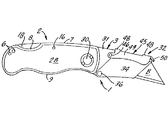
図面、特に、図1〜図7に示した好ましい実施例を参照すると、本発明の万能ナイフ1は、ハンドル2と刃ホルダ3を有する。
Referring to the drawings, and in particular to the preferred embodiment shown in FIGS. 1 to 7, the universal knife 1 of the present invention has a
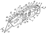
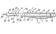
ハンドル2は、一対のハンドル半部2Aと2Bからなり、各半部は、外側壁11と、上縁部7と、下縁部9とを有する。後部スペーサ4がハンドル半部2Aと2Bの間に設けられ、ハンドル半部2Aと2Bを離間した状態に保つとともに、ハンドル半部2Aと2Bの間に空間部5を形成している。スペーサ4と、ハンドル半部2Aおよび2Bは、留め具6により一緒に保持され、この留め具6はスペーサ4とハンドル半部2Aおよび2Bを貫通することによりこれらを一緒に保持する。ハンドル半部2Aと2B(すなわちハンドル2)の上縁部7は、フィンガーノッチ8を有し、ハンドル半部2Aと2B(すなわちハンドル2)の下縁部9は、ユーザの指がハンドル2を握れるように、波状に形成してもよい。所望に応じ、クリップ10をハンドル半部2Aおよび/または2Bの側壁11に取り付けて、万能ナイフ1をユーザのベルトやその他の便利な場所などに固定することができるようにしてもよい。
The
ハンドル半部2Aと2Bの間に介在して、且つ、ハンドル半部2Aと2Bの上縁部7に沿って、ロックレバーアセンブリ15(図3〜図5)が設けられ、このロックレバーアセンブリ15は、ハンドル半部2Aと2Bの間に、ピボットピン16を支点として旋回可能に取り付けられている。このピボットピン16は、2つのハンドル半部2Aおよび2Bとロックレバーアセンブリ15を通って延在する。ロックレバーアセンブリ15は、前方アーム17と後方アーム18をそれぞれ有する2アームレバーである。前方アーム17は、下方に延在するロックフィンガー19を備える。ロックレバーアセンブリ15の後方アーム18の下には、スプリング14(V字形あるいはU字形)が設けられ、このスプリング14は、通常状態では、後方アーム18の下縁部に押し当てられ、ピボットピン16を支点として後方アーム18を上方に、前方アーム17を下方に付勢しており、したがって、後方アーム18はノッチ8上に突出している。ロックレバーアセンブリ15の後方アーム18をスプリング14の作用に抗してノッチ8を介して手指で押し下げると、前方アーム17が上昇する。
Interposed between the handle halves 2 A and 2 B, and, along the
本発明による刃ホルダ3は、互いに一体に形成された後端部31と前端部32を有する。
The
刃ホルダ3の後端部31は、後縁部31Aと、下縁部31Bと、上縁部31Cを有する。刃ホルダ3は、ハンドル半部2Aと2Bの間の空間部5内に、ピボットピン30を支点として旋回可能に取り付けられている。フィンガーノブ41を後端部31に設けると、ハンドル2に対する刃ホルダ3の旋回運動を容易にすることができる。後端部31の上縁部31Cは溝33を有し、刃ホルダ3がその延在状態すなわち展開状態にある時に、ロックアセンブリ15の下方に延在するロックフィンガー19がこの溝33に入り込むようにされている。
The
刃ホルダ3の前端部32は、薄い主壁34と、主壁34上にピボットピン36を支点として旋回可能に取り付けられた薄いガード壁35からなる。主壁34は刃Bを保持することができ、刃Bは、下部切断縁部37と、その上縁部39に設けられた離隔したノッチ38とを有する。主壁34は、主壁34から延在する離隔した一対の突起40を有し、この突起40に刃Bの上部ノッチ38を嵌め込んで、刃Bを主壁34の定位置に保持することができるようになっている。ガード壁35が上昇閉位置にあるとき、ガード壁35は刃Bを覆って刃Bを定位置に保持し、ガード壁35が下方開位置にあるとき、刃Bを露出させる。
The
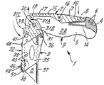
刃ロックアセンブリ45が、刃ホルダ3の上縁部に沿って取り付けられ、刃ホルダ3の後端部31に、ピボットピン46を支点として旋回可能に取り付けられている。刃ロックアセンブリ45はU字クリップ形状であり、分割すなわち分断された上壁48と、上壁48にぶら下がる一対の側壁49と、前方に延在する前方フィンガータブ50とを有する。刃ロックアセンブリすなわちクリップ45をピボットピン46を支点として下方に旋回させると、その側壁49が刃ホルダ3の主壁34とガード壁35を挟み、上壁48が主壁34およびガード壁35ならび刃Bの上にかぶさり、刃Bが定位置にロックされる。刃Bを取り外して交換したい場合、クリップ45を上記フィンガータブ50により上方に旋回させて、主壁34およびガード壁35と刃Bを解放する。これにより、ガード壁35を刃Bから離れる方向に旋回させる(図6に示すように)ことが可能となるため、刃Bを露出させ、刃Bを取り外して交換することが可能となる。
A
図1〜図7の好ましい実施例に示された万能ナイフ1の操作に際しては、万能ナイフを、刃ホルダ3を折り畳まない展開操作状態にして、使用準備状態にする。刃Bは、刃Bの上縁部39のノッチ38まで延在する突起40により、主壁34に保持されている。ロックレバーアセンブリ15の前方アーム17に形成されたロックフィンガー19は、後方アーム18に作用するスプリング14の圧力のために、下方位置にあり、刃ホルダ3に設けた溝33内に位置づけられ、刃ホルダ3をその展開状態に保っている。ロックレバーアセンブリ15の後方アーム18はその上昇位置にあり、ハンドル2の上縁部7のフィンガーノッチ8上に突出している。
In operation of the universal knife 1 shown in the preferred embodiment of FIGS. 1 to 7, the universal knife is put into a deployment operation state in which the
万能ナイフ1を折り畳んだ操作不能状態にしたい場合、ロックアセンブリ15の後方アーム18をスプリング14の付勢力に抗してノッチ8を介して手指で押し下げる。これにより、ロックアセンブリ15の前方アームを上昇させて、溝33からロックフィンガー19を抜き出して刃ホルダ3を解放し、刃ホルダ3をピボットピン30を支点として下方に旋回させる(図4)。これは、フィンガーノブ(又はフィンガーグリップ)41を押し下げることによって行ってもよい。次いで、刃ホルダ3を下方に旋回させ、ハンドル半部2Aと2Bの間の空間部5内に完全に収容する(図5)。後方アーム18に対する圧力が解除されると、スプリング14は、スプリング14の張力により、後方アーム18を移動させて元の上昇位置に戻す。これにより、ロックフィンガー19を刃ホルダ3の後縁部31Aと下縁部31Bに押し当て、刃ホルダ3をその折り畳み状態に保持する。
When the universal knife 1 is to be folded and inoperable, the
刃Bを使用したい場合には、逆の手順をたどる。刃ホルダ3を反対方向に旋回させる。好ましくは、ロックレバーアセンブリ15の後方アーム18を再び手指で押し下げることで、刃ホルダ3の展開を支援する。刃ホルダ3を反時計方向に引き続き回転させると(図4に示すように)、前方アーム17のロックフィンガー19が刃ホルダ3の後端部31に設けた溝33に入り込み、刃ホルダ3をその延長状態に保つ。
If you want to use blade B , follow the reverse procedure. The
刃Bを交換したい場合、刃ホルダ3をその展開状態にして(図6に示すように)、フィンガータブ50によりピボットピン46を支点としてクリップ45を持ち上げる。これにより、ガード壁35が解放され、ピボットピン36を支点として下方にガード壁35を旋回させ、刃Bを露出させる。そこで、刃Bを刃ホルダ3から取り出すことができ、ここに新しい刃Bを取り付けることができる。再び、ガード壁35を上方に旋回させて刃Bを覆う位置に戻し、クリップ45を下降させることにより刃Bと主壁34およびガード壁35を定位置にロックする。
When it is desired to replace the blade B , the
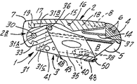
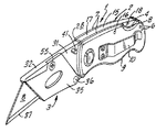
図8〜図11に示す万能ナイフ1の実施例を参照すると、本実施例は、図1〜図7に示した万能ナイフの実施例と同様のものであり、同様の部分には、同一の参照番号を付して示す。 Referring to the embodiment of the universal knife 1 shown in FIGS. 8 to 11, this embodiment is similar to the embodiment of the universal knife shown in FIGS. These are indicated by reference numbers.
全ての点で、本実施例の構造と動作は、図1〜図7に示した実施例と同様である。しかしながら、本実施例において、刃ホルダ3の旋回可能なガード壁35は、ネジ部材55により定位置に保持される。このネジ部材55は、旋回可能なガード壁35を開口部57において貫通し、開口部56において主壁34内に延在する。刃Bを取り外したい場合、ネジ部材55を取り外して、ガード壁35をピボットピン36を支点として下方に回転させ刃Bを露出させると、この刃を取り外して、交換することができる。刃Bを交換した後、ガード壁35をピボットピン36を支点として上方に回転させて刃Bを覆う動作位置に戻す。ネジ部材55を、再び、開口部57−56を貫通して取り付ければ、ガード壁35と刃Bを定位置に保持することができる。
In all respects, the structure and operation of this embodiment are the same as those of the embodiment shown in FIGS. However, in this embodiment, the
なお、本発明は上記の実施例に限定されるものではなく、請求項の範囲を逸脱することなく種々の変形が可能であることは、当業者であれば明らかであろう。 It should be apparent to those skilled in the art that the present invention is not limited to the above embodiments, and that various modifications can be made without departing from the scope of the claims.
1 万能ナイフ
2 ハンドル
2A、2B ハンドル半部
3 刃ホルダ
4 後部スペーサ
5 空間部
6 留め具
7 上縁部
8 ノッチ
9 下縁部
10 クリップ
11 外側壁
14 スプリング
15 ロックレバーアセンブリ
16 ピボットピン
17 前方アーム
18 後方アーム
19 ロックフィンガー
30 ピボットピン
31 後端部
31A 後縁部
31B 下縁部
31C 上縁部
32 前端部
33 溝
34 主壁
35 ガード壁
36 ピボットピン
37 切断縁部
38 ノッチ
39 上縁部
40 突起
41 フィンガーノブ
45 刃ロックアセンブリ
46 ピボットピン
48 上壁
49 側壁
50 前方フィンガータブ
55 ネジ部材
56、57 開口部
B 刃
1
B blade
Claims (44)
44. The blade holder according to claim 43, wherein the blade holding means has a pair of protrusions provided on the main wall of the blade holder, and the protrusions can enter respective corresponding grooves provided on the blade. Universal knife.
Applications Claiming Priority (1)
| Application Number | Priority Date | Filing Date | Title |
|---|---|---|---|
| US10/437,089 US7040022B2 (en) | 2002-12-10 | 2003-05-13 | Utility knife |
Publications (2)
| Publication Number | Publication Date |
|---|---|
| JP2004337610A true JP2004337610A (en) | 2004-12-02 |
| JP2004337610A5 JP2004337610A5 (en) | 2005-05-26 |
Family
ID=33417305
Family Applications (1)
| Application Number | Title | Priority Date | Filing Date |
|---|---|---|---|
| JP2004143172A Pending JP2004337610A (en) | 2003-05-13 | 2004-05-13 | Utility knife |
Country Status (2)
| Country | Link |
|---|---|
| JP (1) | JP2004337610A (en) |
| MX (1) | MXPA04004480A (en) |
Cited By (3)
| Publication number | Priority date | Publication date | Assignee | Title |
|---|---|---|---|---|
| JP2007325663A (en) * | 2006-06-06 | 2007-12-20 | Olfa Corp | Safety snap-off blade knife |
| JP2009511138A (en) * | 2005-10-13 | 2009-03-19 | マルトール・コマンデイトゲゼルシヤフト | Cutter |
| WO2022093443A1 (en) * | 2020-10-28 | 2022-05-05 | Alliance Sports Group, L.P. | Tool with replaceable component |
-
2004
- 2004-05-12 MX MXPA04004480 patent/MXPA04004480A/en active IP Right Grant
- 2004-05-13 JP JP2004143172A patent/JP2004337610A/en active Pending
Cited By (3)
| Publication number | Priority date | Publication date | Assignee | Title |
|---|---|---|---|---|
| JP2009511138A (en) * | 2005-10-13 | 2009-03-19 | マルトール・コマンデイトゲゼルシヤフト | Cutter |
| JP2007325663A (en) * | 2006-06-06 | 2007-12-20 | Olfa Corp | Safety snap-off blade knife |
| WO2022093443A1 (en) * | 2020-10-28 | 2022-05-05 | Alliance Sports Group, L.P. | Tool with replaceable component |
Also Published As
| Publication number | Publication date |
|---|---|
| MXPA04004480A (en) | 2005-07-26 |
Similar Documents
| Publication | Publication Date | Title |
|---|---|---|
| US7040022B2 (en) | Utility knife | |
| US6968622B2 (en) | Utility knife | |
| US7007392B2 (en) | Utility knife | |
| US7480997B2 (en) | Foldable knife | |
| JP2005261944A (en) | Utility knife | |
| US20100299935A1 (en) | Folding utility knife | |
| US7380341B2 (en) | Foldable knife | |
| JP2005324026A (en) | Utility knife | |
| US20050204567A1 (en) | Folding utility knife | |
| US20100175267A1 (en) | Utility knife including a locking mechanism and/or ratcheting mechanism | |
| JP2004337612A (en) | Utility knife | |
| CA2481333C (en) | Foldable utility knife | |
| JP2004337610A (en) | Utility knife | |
| JP2004337610A5 (en) | ||
| JP2009078545A (en) | Binder and file | |
| GB2413983A (en) | Foldable utility knife having a blade holder and storage compartment | |
| JP2009196105A (en) | Foldable cutting knife |
Legal Events
| Date | Code | Title | Description |
|---|---|---|---|
| A521 | Written amendment |
Effective date: 20041001 Free format text: JAPANESE INTERMEDIATE CODE: A523 |
|
| A621 | Written request for application examination |
Effective date: 20050125 Free format text: JAPANESE INTERMEDIATE CODE: A621 |
|
| A131 | Notification of reasons for refusal |
Free format text: JAPANESE INTERMEDIATE CODE: A131 Effective date: 20080116 |
|
| A02 | Decision of refusal |
Free format text: JAPANESE INTERMEDIATE CODE: A02 Effective date: 20080618 |