【0001】
【発明の属する技術分野】
本発明は、液体移動手段に関し、特に、液体そのもの、あるいは、液体に溶解又は内包又は吸着又は付着しているものを移動させる液体移動手段に関するものである。又は、液体そのもの、あるいは、液体に溶解又は内包又は吸着又は付着しているものを分配する液体分配手段に関するものである。
【0002】
【従来の技術】
従来、電気毛管現象は、液滴の形状をコントロールして光学的特性を変化させる機構として利用されてきた。その際、液滴の接触面積を電気的に変化させたり、液滴の表面形状を電気的に変化させることにより、形状のコントロールが行われる(特許文献1、特許文献2)。
【0003】
【特許文献1】
特開平9−311643号公報
【0004】
【特許文献2】
特開2000−356708号公報
【0005】
【発明が解決しようとする課題】
しかしながら、電気毛管現象を利用するもの、あるいはその他の現象を利用するものにおいて、液滴を電気的に制御して所望の方向へ移動することは行われてはいなかった。
【0006】
本発明は従来技術のこのような現状に鑑みてなされたものであり、その目的は液体そのもの、あるいは、液体に溶解又は内包又は吸着又は付着しているものを移動させる液体移動手段を提供することである。又は、液体そのもの、あるいは、液体に溶解又は内包又は吸着又は付着しているものを分配する液体分配手段を提供することである。
【0007】
【課題を解決するための手段】
上記目的を達成する本発明の液体移動手段は、電解質からなる液滴に接触した第1電極と、前記液滴に対して絶縁層を挟んで複数の並列配置された第2電極と、前記第1電極に対して前記複数の並列配置された第2電極に印加する印加電圧を電極毎に個別に制御する制御手段とを有し、前記制御手段は、前記液滴を前記絶縁層に沿って移動させるように、前記複数の並列配置された第2電極に印加する印加電圧を電極毎に個別に制御可能に構成されていることを特徴とするものである。
【0008】
この場合に、複数の並列配置された第2電極は、1列に列に沿って並列配置されているものとすることもできるし、1列から途中で複数の列になるように列に沿って並列配置されているものとすることもできるし、さらには、2次元的に並列配置されているものとすることもできる。
【0009】
列に沿って並列配置されている場合には、その複数の並列配置された第2電極は、基板表面に設けられた溝に沿ってその溝内に並列配置されているものとすることができる。
【0010】
また、第1電極は液滴に対して絶縁層とは反対側に配置されているものとすることができる。
【0011】
その場合に、第1電極は膜状の電極から構成することができる。
また、第1電極は、絶縁層に対して複数の並列配置された第2電極とは反対側に配置されており、かつ、液滴に対して同じ側に配置されているものとすることができる。
【0012】
この場合に、第1電極は線状の電極からなるものとすることができる。
【0013】
また、複数の並列配置された第2電極は管状体の内面にその軸に沿って並列配置されているものとすることができる。
【0014】
また、液滴が複数個同時に存在するようにしてもよい。
【0015】
また、液滴がレンズ作用をするものとすることができる。
【0016】
また、液滴には被移動物が吸着、付着、溶解あるいは内包されていてもよい。
【0017】
また、少なくとも液滴と絶縁層と複数の並列配置された第2電極とを通して照明光を照射する照明手段と、液滴で集光あるいは発散された光を受光する複数の並列配置された受光素子とを備え、その受光素子で受光された受光強度信号から液滴の位置をモニターするように構成することもできる。
【0018】
本発明においては、電解質からなる液滴に接触した第1電極と、その液滴に対して絶縁層を挟んで複数の並列配置された第2電極と、第1電極に対して複数の並列配置された第2電極に印加する印加電圧を電極毎に個別に制御する制御手段とを有し、その制御手段は、液滴を絶縁層に沿って移動させるように、複数の並列配置された第2電極に印加する印加電圧を電極毎に個別に制御可能に構成されているので、液滴の液体そのもの、あるいは、その液滴に溶解又は内包又は吸着又は付着している物を所定方向あるいは任意の方向に所定距離だけ移動又は振り分けることができる。
【0019】
【発明の実施の形態】
以下に、図面を参照にして本発明の液体移動手段の原理と実施例を説明する。
【0020】
本発明は、電解質からなる液滴を、電圧の印加位置を制御することにより移動させるものである。
【0021】
図1は、本発明の液体移動手段の原理を説明するための図である。本発明の液体移動手段では、図1(a)に示すように、基板7と基板8とを平行に対向配置している。その際、基板7と基板8の間には、所定の間隔で隙間9が形成されている。一方の基板7の内面、すなわち基板8側の面には、第1の電極が設けられている。この第1の電極は、共通電極(共通電極膜)2である。この共通電極2には、例えば金のような、化学反応に対して安定で撥水性の材料が用いられる。他方の基板8の内面、すなわち基板7側の面には、第2の電極が設けられている。この第2の電極は、多数の分割電極31 〜36 の集合からなる分割電極群3である。分割電極31 〜36 は、相互に並列配置されている。また、分割電極群3の表面は、アモルファスフッ素樹脂(例:商品名サイトップ(旭ガラス(株)))膜のような絶縁膜4で覆われている。よって、所定の間隔とは、正確には、共通電極2から絶縁膜4までの距離ということになる。
【0022】
前述のように、基板7と基板8の間には、所定の間隔をもつ隙間9が形成されている。この隙間9の間隔は、例えば1μl(マイクロリットル)程度の液滴1が共通電極膜2と絶縁膜4とに接して孤立する程度になっている。ここで、液滴1としては、食塩水等の電解質溶液が用いられる。図1では、液滴1と絶縁膜4が比較的濡れ性良く入っているように描かれている。しかしながら、絶縁膜4の表面エネルギーが低い場合には、液滴1はより球形に近い形で間隔9内に孤立して入る。
【0023】
共通電極2と分割電極群3の分割電極31 〜36 との間には、直流電源5が設けられている。そして、分割電極群3側には、スイッチ群6が接続されている。スイッチ群6のそれぞれスイッチ61 〜66 は、分割電極群3の分割電極31 〜36 と一対一に対応するように接続されている。よって、スイッチ群6のうち、例えばスイッチ63 が接続されると、対応する分割電極33 に直流電源5の電圧が印加されるようになっている。また、スイッチ群6のそれぞれのスイッチ61 〜66 は、制御装置10に接続されている。よって、制御装置10により、個々のスイッチの開閉動作が制御できるようになっている。
【0024】
このような配置で、制御装置10により、スイッチ群6の全てのスイッチ61 〜66 を開放した状態にする。この状態が、図1(a)である。この状態では、隙間9、すなわち共通電極2と絶縁膜4の間に位置する液滴1には、何ら力が加わらない。よって、液滴1は、そのままの位置を保つ。次に、このような状態から、図1(b)に示すように、スイッチ63 、64 、65 を制御装置10により同時に閉じる。
【0025】
ここで、スイッチ63 は分割電極33 に接続され、スイッチ64 は分割電極34 に接続され、スイッチ65 は分割電極35 に接続されている。また、分割電極33 、34 は液滴1の最初の位置(点線)の右側部分に対応する位置し、分割電極35 は分割電極33 、34 より右側に位置している。よって、スイッチ63 、64 、65 が閉じると、直流電源5の一方の極(図ではプラス)の電極からは、プラス(図の場合)の電荷が共通電極膜2に流れ込む。そして、そのプラス電荷は液滴1の電解質を通して絶縁膜4に接する面に集まる。一方、直流電源5の他方の極(図ではマイナス)の電極からは、マイナス(図の場合)の電荷が、スイッチ63 、64 、65 を通して分割電極33 、34 、35 に流れ込む。そして、絶縁膜4に接する側に集まる。このとき、液滴1の絶縁膜4に集まったプラスの電荷の中心と、分割電極33 、34 、35 の絶縁膜4に接する側に集まったマイナスの電荷の中心とは、プラス側が相対的に図の左に位置し、マイナス側が相対的に図の右に位置する。よって、両者の間にずれが生じ、液滴1には電気的引力が作用し、液滴1は点線の位置から実線の位置へ矢印方向へ移動することになる。
【0026】
次に、分割電極33 のスイッチ63 を切り、その代わりに、液滴1位置(破線)の右側の分割電極36 のスイッチ66 閉じる。この状態が図1(c)である。分割電極33 は、図1(b)の状態での液滴1の位置(破線)の左側部分に位置にある電極である。一方、分割電極36 は、液滴1の位置(破線)の右側部分に位置にある電極である。よって、図1(b)で液滴1が移動したのと同様の理由で、液滴1は破線の位置から実線の位置へ矢印方向にさらに移動することになる。
【0027】
このように、本発明の液体移動手段(液体移動装置)は、共通電極2と、複数の分割電極31 〜36 と、この複数の分割電極31 〜36 の表面(共通電極2側)に設けられた絶縁膜4と、割電極31 〜36 に印加する印加電圧を電極毎に個別に制御する制御装置10を備えている。そして、共通電極2と絶縁膜4の隙間は、電解質からなる液滴1が両側で接触するような間隔となっている。そして、制御装置10により液滴1を絶縁膜4に沿って移動させるように、複数の並列配置された分割電極31 〜36 に印加する印加電圧を順次個別にON・OFF するように制御することで、液滴1の液体を所定方向に移動させることができる。
【0028】
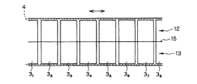
図2は、本発明の液体移動手段を具体的に構成した例である。ここでは、構成を説明するために、透視斜視図を用いる。この構成では、基板8に分割電極群3が設けられている。そして、基板8の表面に、液滴1をガイドする(液滴1の移動路となる)V溝11を所定の形状で形成されている。このV溝11の表面には、後記するような分割電極群3とその上を覆う絶縁膜4が設けられている。そして、V溝11が形成された基板8上に、基板7を重ね合わせて一体化している。このようにすることで、1つの形態の液体移動手段が構成される。なお、基板7の下面(基板8側の面)には、共通電極膜2が形成されている。液滴1をガイドするV溝11によって形成される空間は、その底を形成する2つの斜面12、13と、その斜面12、13間に位置する稜線15と、天井14を構成する共通電極膜2とからなる。そして、底の斜面12、13上には、以下に例示するような分割電極群3とその上を覆う絶縁膜4が形成される。
【0029】
図3は、分割電極群3の形状の最も簡単な例を示す平面図である。この分割電極群3は、V溝11の底面を構成する2つの斜面12、13上に設けられている。各分割電極31 〜38 は、底の稜線15に直交する矩形形状をしている。そして、各分割電極31 〜38 を覆うように、斜面12、13上に絶縁膜4が形成されている。このV溝11中に入れられた液滴1(図1)は、制御装置10によるスイッチ群6の個々のスイッチ61 〜68 (図示なし)の開閉制御により、底の稜線15に沿った右あるいは左方向に移動させられる。
【0030】
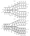
図4は、分割電極群3の形状の変形例を示す平面図である。図4の(a)、(b)何れも、液滴1を移動させるのに適した分割電極31 〜38 の形状を示す。これらの分割電極群3は、矢印方向、すなわち図の左から右へ、液滴1を移動させるのに適している。図4(a)の分割電極31 〜38 は、何れも平面図で“〈”の形状をしている。そして、分割電極31 〜38 の底の稜線15近傍の部分が、左側へ突き出た突起部分3’となっている。さらに、隣接する分割電極31 〜38 の凹部へ、その突起部分3’が入り込む形状になっている。この突起部分3’は、隣接する分割電極から液滴1を、図の右方向へ引っ張る役目を持つ。このような構成により、液滴1の移動を、よりスムーズに行うことができる。図4(b)の場合は、その突起部分3’の形状をより明確で尖端状に構成した例である。
【0031】
図5は、分割電極群3の形状の別の変形例を示す平面図である。図5の(a)、(b)何れも、液滴1を移動させるのに適した分割電極31 〜38 の形状を示す。これらの分割電極群3は、両矢符方向、すなわち図の左から右、右から左の両方向に、液滴1を移動させるのに適している。図5(a)の分割電極31 〜38 は、両方向に移動させるのに適するように、図4(b)の形状を変形したものである。、各分割電極31 〜38 の両側の稜線15近傍の部分に、2つの突起部分3’、3’が設けられている。そして、隣接する分割電極31 〜38 の凹部へ、それら突起部分3’、3’が入り込む形状になっている。図5(b)の場合は、その突起部分3’、3’の形状を矩形に構成した例である。
【0032】
図6は、本発明の液体移動手段を具体的に構成した別の例である。ここでは、構成を説明するために、図2と同様の透視斜視図で示している。この構成では、液滴1をガイドするV溝11を、途中の分岐点110 で、2つのV溝111 、112 へ分岐している。この2つのV溝111 、112 は、いずれも同様の形状を有している。制御装置10によるスイッチ群6(図1)の制御により、液滴1は、V溝11中を分岐点110 方向へガイドされる。分岐点110 に到達した液滴1は、この分岐点110 で、V溝111 又はV溝112 の何れかへ振り分けられる(分配される)。V溝111 又はV溝112 のどちらを選択するかは、制御装置10によって決めることができる。なお、V溝11、111 、112 自体の構成は、図2の場合と同様である。よって、ここでは、振り分けるための分割電極群3の構成例を図7を参照にして説明する。
【0033】
図7(a)は、分割電極群3の例を示す平面図である。この分割電極群3により、分岐点110 を介して、1個のV溝11から2つのV溝111 、112 へ液滴1をガイドして振り分けることができる。図7(a)における各分割電極の形状は、図4(a)の例の形状としたものである。V溝11での分割電極は、分割電極31 〜32 からなる。また、分岐点110 以降のV溝111 の分割電極は、分割電極331〜3101 からなる。V溝112 の分割電極は、分割電極332〜3102 からなる。分割電極331と332は、V溝11中で分けられ、分割電極341はV溝11とV溝111 にかかり、分割電極342はV溝11とV溝112 にかかっている。
【0034】
このような構成において、液滴1を振り分ける方法について説明する。まず、V溝11からV溝112 へ、液滴1を振り分けるには、図7(b)に斜線ハッチで示すように、分割電極31 〜32 、332〜3102 に順に図の左から右へ電圧を印加する。これにより、液滴1はV溝11からV溝112 へ導かれる。これとは逆に、V溝11からV溝111 へ液滴1を振り分けるには、分割電極31 〜32 、331〜3101 に順に図の左から右へ電圧を印加するように制御すればよい。この例では、液滴1を分配する構成を示しているが、液滴1を移動させているので、分配手段も移動手段に含まれるといえる。
【0035】
図8は、液滴1を、2次元方向の任意の方向へ移動可能な形態の斜視図である。主として、基板8上に配置される分割電極群3の形状と配置を示す。基板8の上には、分割電極群3が2次元の碁盤の目状に配置されている。それそれの分割電極は、行方向に、分割電極311〜31m、321〜32m、・・・・、3n1〜3nmが配置されている。そして、その上全面を、図示しない絶縁膜4(図1)で覆っている。そして、その絶縁膜4上に微小な隙間9を設けて、下面に共通電極2を設けている。この共通電極2は、基板7に設けられている。隙間9には、液滴1が共通電極膜2と絶縁膜4とに接して孤立するように入れられている。
【0036】
このような配置で、分割電極への電圧の印加を、順に連続的に変更(ON・OFF )する。これにより、液滴1を、太い矢印で示したように2次元の任意の方向へ移動することができる。
【0037】
図9は、液滴1を、2次元方向の任意の方向へ移動することができる別の形態の平面図である。この形態においても、分割電極群3は、分割電極311〜31m、321〜32m、・・・・、3n1〜3nmで構成されている。そして、分割電極群3と対向配置された共通電極2’とは、同じ面上に図示の例のように配置される。ただし、図示は省いてあるが、分割電極311〜31m、321〜32m、・・・・、3n1〜3nmは、共通の基板上に設けられている。そして、その上全面を、図示しない絶縁膜4で覆っている。そしてさらに、その上に、共通に接続された平行な線状、あるいは櫛歯状の共通電極2’が露出して設けられている。このように、1つの基板において、分割電極311〜31m、321〜32m、・・・・、3n1〜3nmが絶縁膜4で覆われ、共通電極2’が露出している。なお、共通電極2’と分割電極群3は、直流電源に接続されている。
【0038】
このような基板上に、液滴1を置く。そして、分割電極に印加する電圧を、順に連続的に変更(ON・OFF )する。これにより、図8の場合と同様に、液滴1を2次元の任意の方向へ移動させることができる。この形態は、以上の説明から明らかなように、液滴1の下面のみで、共通電極2’と、分割電極311〜31m、321〜32m、・・・・、3n1〜3nm(絶縁膜4を含む)の対向配置が行われている。すなわち、液滴1の上面が、何らの部材にも接触していないで自由になっている例である。
【0039】
ところで、図1の構成では、液滴1に接触する共通電極膜2は撥水性のものとしたが、これに限定されるわけではない。例えば、図10に示すように、共通電極膜2を親水性のもので構成してもよい。その場合は、液滴1の形状は、共通電極膜2と分割電極群3の間に電圧を印加した状態では、断面が両凹レンズ状になる。
【0040】
次に、図11に、液滴1をパイプの孔に沿って前後に移動させる形態の透視斜視図を示す。この例の場合は、中空の円筒体(パイプ)20の内面に、分割電極群3を構成する分割電極31 〜37 が設けられている。各分割電極31 〜37 は、円筒体20の軸方向に分割されている。そして、内周方向に弧状に延びる形状となっている。弧状の分割電極31 〜37 の端部間には、配線のための領域21が設けられている。この領域21には、共通電極2’と、各分割電極31 〜37 への電極線が設けられている。そして、円筒体20の内面上(領域21)を通る結線を介して、各分割電極31 〜37 が、スイッチ群6のそれぞれスイッチ61 〜67 に接続されている。そして、図示を省いてあるが、円筒体20の内面全面であって、これら分割電極31 〜37 とそれらを結ぶ結線とが絶縁膜4(図1)で覆われている。また、その上に、円筒体20の軸方向に伸びる線状の共通電極2’が円筒体20の内面に露出して設けられている。この共通電極2’は直流電源5の一方の極に接続されている。同様に、分割電極群3は、電極線及びスイッチ群6を介して、直流電源の他方の極に接続されている。そして、スイッチ群6のそれぞれのスイッチ61 〜67 は、制御装置10により、個々に開閉動作が制御されるようになっている。
【0041】
したがって、図11の構成においては、制御装置10によりスイッチ61 〜67 の開閉を順に制御することにより、分割電極群3に印加する印加電圧を制御(ON・OFF )することができる。例えば、上の分割電極から下の分割電極へ、順に電圧の印加状態を変化させる。このようにすると、円筒体20の孔内に入れられた液滴1を、下方へ移動させるようにすることができる。
【0042】
図12(a)、(b)は、図11の形態の液体移動手段の適用例を示す図である。図12(a)の例の場合も、円筒体20の内面には、絶縁膜4(不図示)が設けられている。この絶縁膜4は、分割電極31 〜37 と、それらを結ぶ結線とを、全面で覆っている。ただし、この例では、絶縁膜4が親水性のもので構成されている。一方、図12(b)の例の場合は、絶縁膜4が破線よりA方向の上側で撥水性のもので構成され、破線よりB方向の下側で親水性のもので構成されている。
【0043】
図12(a)の場合は、上記のように、円筒体20の内面の絶縁膜4が親水性である。そのため、円筒体20の孔内に入れられた液滴1は、円筒体20の中心軸を含む断面内では両凹レンズ状になる。したがって、液滴1自体を両凹レンズとして用いることが可能になる。そして、前記のように、分割電極群3に印加する印加電圧を制御することにより、図12(a)の破線位置の液滴1’から実線の位置の液滴1へ移動調節することができる。よって、例えば、液滴1からなる両凹レンズの焦点調節として、本発明の液体移動手段を用いることができる。
【0044】
図12(b)の場合は、上記のように、円筒体20の内面の絶縁膜4が破線よりA方向の上側で撥水性である。そのため、その領域の円筒体20の孔内に入れられた液滴11 は、円筒体20の中心軸を含む断面内では両凸レンズ状になる。また、破線よりB方向の下側では絶縁膜4は親水性である。よって、その領域の円筒体20の孔内に入れられた液滴12 は、円筒体20の中心軸を含む断面内では両凹レンズ状になる。したがって、液滴11 からなる両凸レンズと液滴12 からなる両凹レンズとを組み合わせてレンズ系とすることができる。しかも、分割電極群3に印加する印加電圧を制御することにより、図12(b)の矢印で示すように、この液滴11 の両凸レンズと液滴12 の両凹レンズを独立に円筒体20の中心軸方向に位置調節することができる。このようにすることで、焦点距離可変レンズ系(ズームレンズ系)を構成することができる。なお、図12(b)中の符号22は、円筒体20の側面に設けられた通気孔であり、液滴11 と液滴12 で挟まれた空間の体積変化に応じて外気を自由に導入排出するためのものである。
【0045】
図13(a)、(b)は、図11の形態の液体移動手段の別の適用例を示す図である。図13(a)、(b)何れの例においても、円筒体20の内面で設けられた絶縁膜4(不図示)は、親水性のもので構成されている。この絶縁膜4は、分割電極31 〜37 と、それらを結ぶ結線とを、全面で覆っている。そして、図13(a)の場合は、円筒体20の孔内に入れられた液滴1には、機械的な微小物体、分子生物学的なもの(例えば、DNA)等の被移動物25が吸着されている。あるいは、被移動物25が付着、溶解、内包されている。また、図13(b)の場合は、円筒体20の孔内に入れられた液滴1には、レンズ26が吸着、付着あるいは内包されている。そして、分割電極群3に印加する印加電圧を制御することにより、何れの場合も、被移動物25あるいはレンズ26を、例えば点線位置から実線位置へ移動させることができる。
【0046】
図14は、液体移動手段で移動される液滴1の位置を、モニターする形態の1例を示す図である。ここでは、図8の2次元方向の任意の方向へ移動可能な液体移動手段において、液滴1の位置をモニターする機構を示す。図14(a)の斜視図に示すように、基板8の上には分割電極群3が2次元の碁盤の目状に配置されている。それそれの分割電極は、行方向に分割電極311〜31m、321〜32m、・・・・、3n1〜3nmが配置されている。そして、その上全面を、図14(b)に示すように、絶縁膜4で覆っている。そして、その絶縁膜4上に微小な隙間9が設けられている。この隙間9を挟んで、下面に共通電極膜2を設けた基板7が配置されている。そして、隙間9には、液滴1が共通電極膜2と絶縁膜4とに接して孤立するように入れられている。そして、基板7、共通電極膜2、分割電極群3、基板8はこの例の場合全て透明に構成されている。
【0047】
そして、このような液体移動手段の基板8の外側には、基板8と平行に、受光素子群32が配置されている。受光素子群32は基板31上に設けられている。そして、碁盤の目状に配置された受光素子3211〜321m、3221〜322m、・・・・、32n1〜32nmからなるCCD等を有する。この光素子3211〜321m、3221〜322m、・・・・、32n1〜32nmは、凸レンズ形状をした液滴1の集光位置近傍(焦点面近傍)に配置されている。また、受光素子3211〜321m、3221〜322m、・・・・、32n1〜32nmの各々は、分割電極311〜31m、321〜32m、・・・・、3n1〜3nmに対応した位置に配置されている。
【0048】
このような構成であるので、共通電極膜2を設けた基板7側から全面に例えば平行光30を照射する。この状態で、制御装置10により分割電極群3に印加する印加電圧を制御し、液滴1を所定の方向へ移動させる。すると、液滴1が存在する位置では、その位置に入射する平行光30の成分は、対応する位置の受光素子3211〜321m、3221〜322m、・・・・、32n1〜32nmに集光される。例えば、液滴1が図14(b)の破線位置(符号1’)にあるときは、受光素子群32からは図14(c)に破線で示すような受光強度と位置関係の信号が得られる。一方、液滴1が図14(b)の実線位置(符号1)にあるときは、受光素子群32からは図14(c)に実線で示すような受光強度と位置関係の信号が得られる。このように、その信号のピーク位置で、液滴1の位置がモニターできる。したがって、そのモニター信号を制御装置10へフィードバックすることにより、液滴1のより正確な位置制御が可能になる。あるいは、このような信号のピーク位置を表示装置上に表示することにより、微小な液滴1の位置を明確に表示することができる。なお、液滴1が図10の場合のように断面が両凹レンズ状の場合にも、例えば平行光30を照射すると、その周囲の境界で入射光が散乱反射される。よって、受光強度と位置関係の信号にはその境界を示す変化が生じる。その結果、信号処理により液滴1の位置がモニターできる。
【0049】
以上、本発明の液体移動手段をその原理と実施形態、実施例に基づいて説明してきたが、本発明はこれら実施形態、実施例に限定されず種々の変形が可能である。
【0050】
[1] 電解質からなる液滴に接触した第1電極と、前記液滴に対して絶縁層を挟んで複数の並列配置された第2電極と、前記第1電極に対して前記複数の並列配置された第2電極に印加する印加電圧を電極毎に個別に制御する制御手段とを有し、前記制御手段は、前記液滴を前記絶縁層に沿って移動させるように、前記複数の並列配置された第2電極に印加する印加電圧を電極毎に個別に制御可能に構成されていることを特徴とする液体移動手段。
【0051】
[2] 前記複数の並列配置された第2電極は、1列に列に沿って並列配置されていることを特徴とする[1]記載の液体移動手段。
【0052】
[3] 前記複数の並列配置された第2電極は、1列から途中で複数の列になるように列に沿って並列配置されていることを特徴とする[1]記載の液体移動手段。
【0053】
[4] 前記複数の並列配置された第2電極は、2次元的に並列配置されていることを特徴とする[1]記載の液体移動手段。
【0054】
[5] 前記複数の並列配置された第2電極は、基板表面に設けられた溝に沿ってその溝内に並列配置されていることを特徴とする[2]又は[3]記載の液体移動手段。
【0055】
[6] 前記第1電極は前記液滴に対して前記絶縁層とは反対側に配置されていることを特徴とする[1]から[5]の何れか1項記載の記載の液体移動手段。
【0056】
[7] 前記第1電極は膜状の電極からなることを特徴とする[6]記載の記載の液体移動手段。
【0057】
[8] 前記第1電極は、前記絶縁層に対して前記複数の並列配置された第2電極とは反対側に配置されており、かつ、前記液滴に対して同じ側に配置されていることを特徴とする[1]から[5]の何れか1項記載の記載の液体移動手段。
【0058】
[9] 前記第1電極は線状の電極からなることを特徴とする[8]記載の記載の液体移動手段。
【0059】
[10] 前記複数の並列配置された第2電極は管状体の内面にその軸に沿って並列配置されていることを特徴とする[8]又は[9]記載の液体移動手段。
【0060】
[11] 前記液滴が複数個同時に存在することを特徴とする[1]から[10]の何れか1項記載の記載の液体移動手段。
【0061】
[12] 前記液滴がレンズ作用をすることを特徴とする[1]から[11]の何れか1項記載の記載の液体移動手段。
【0062】
[13] 前記液滴には被移動物が吸着、付着、溶解あるいは内包されていることを特徴とする[1]から[11]の何れか1項記載の記載の液体移動手段。
【0063】
[14] 少なくとも前記液滴と前記絶縁層と前記複数の並列配置された第2電極とを通して照明光を照射する照明手段と、前記液滴で集光あるいは発散された光を受光する複数の並列配置された受光素子とを備え、前記受光素子で受光された受光強度信号から前記液滴の位置をモニターするように構成されていることを特徴とする[1]から[13]の何れか1項記載の記載の液体移動手段。
【0064】
【発明の効果】
以上の説明から明らかなように、本発明の液体移動手段によると、電解質からなる液滴に接触した第1電極と、その液滴に対して絶縁層を挟んで複数の並列配置された第2電極と、第1電極に対して複数の並列配置された第2電極に印加する印加電圧を電極毎に個別に制御する制御手段とを有し、その制御手段は、液滴を絶縁層に沿って移動させるように、複数の並列配置された第2電極に印加する印加電圧を電極毎に個別に制御可能に構成されているので、液滴の液体そのもの、あるいは、その液滴に溶解又は内包又は吸着又は付着している物を所定方向あるいは任意の方向に所定距離だけ移動又は振り分けることができる。
【0065】
本発明の液体移動手段は、上記実施形態、実施例以外に、本発明を限定するものではないが、例えば、ディスプレイ、分析機器、マイクロマシン、光学装置、玩具等に適用することができる。
【図面の簡単な説明】
【図1】本発明の液体移動手段の原理を説明するための図であり、(a)は電圧の印加がない状態、(b)は一部の分割電極に電圧を印加した状態、(c)は電圧を印加する分割電極を移動させるて液滴を移動させた状態を示す図である。
【図2】本発明の液体移動手段を具体的に構成する場合の1つの形態を説明するための透視斜視図である。
【図3】図2のV溝に設ける分割電極群の形状の1例を示す平面図である。
【図4】図2のV溝に設ける分割電極群の形状の変形例であって一方向に液滴を移動させる例の平面図であり、(a)は1つの形状を、(b)は他の形状を示す図である。
【図5】図2のV溝に設ける分割電極群の形状の変形例であって両方向に液滴を移動させる例の平面図であり、(a)は1つの形状を、(b)は他の形状を示す図である。
【図6】本発明の液体移動手段の別の形態を説明するための図2と同様の透視斜視図である。
【図7】図6の分岐点を介して1個のV溝から2つのV溝へ液滴をガイドして振り分けるための分割電極群の例を示す平面図(a)と、液滴を一方のV溝へ振り分ける場合に電圧を印加する分割電極を示す図(b)である。
【図8】液滴を2次元方向の任意の方向へ移動可能な1つの形態の斜視図である。
【図9】液滴を2次元方向の任意の方向へ移動可能な別の形態の平面図である。
【図10】共通電極膜を親水性のもので構成した場合に電圧を印加する分割電極を移動させるて液滴を移動させた状態を示す図である。
【図11】液滴をパイプの孔に沿って前後に移動させる形態の透視斜視図である。
【図12】図11の形態の液体移動手段の適用例を示す図であり、(a)は液滴からなる両凹レンズの焦点調節に用いる例、(b)は液滴の両凸レンズと別の液滴の両凹レンズからなる焦点距離可変レンズ系を構成する例を示す図である。
【図13】図11の形態の液体移動手段の別の適用例を示す図であり、(a)は液滴に被移動物を吸着、付着、溶解、内包させて移動させる例、(b)はレンズを吸着、付着、内包させて移動させる例を示す図である。
【図14】本発明の液体移動手段で移動される液滴の位置をモニターする形態の1例を示す図であり、(a)は全体の斜視図、(b)は一部断面図、(c)は信号波形図である。
【符号の説明】
1、1’、11 、12 …液滴
2…共通電極膜
2’…共通電極
3…分割電極群
31 〜38 、331〜3101 、332〜3102 、311〜31m、321〜32m、・・・・、3n1〜3nm…分割電極
3’…分割電極の突起部分
4…絶縁膜
5…直流電源
6…スイッチ群
61 〜67 …スイッチ
7、8…基板
9…間隔
10…制御装置
11、111 、112 …V溝
110 …V溝の分岐点
12、13…V溝の斜面
14…天井
15…V溝の稜線
20…円筒体(パイプ)
21…弧状の分割電極の端部間の隙間
22…通気孔
25…被移動物
26…レンズ
30…平行光
31…基板
32…受光素子群
3211〜321m、3221〜322m、・・・・、32n1〜32nm…受光素子[0001]
TECHNICAL FIELD OF THE INVENTION
The present invention relates to a liquid moving means, and more particularly to a liquid moving means for moving a liquid itself, or a substance dissolved, contained, adsorbed, or attached to a liquid. Alternatively, the present invention relates to a liquid distributing means for distributing a liquid itself, or a substance dissolved, contained, adsorbed, or attached to the liquid.
[0002]
[Prior art]
Conventionally, the electrocapillary phenomenon has been used as a mechanism for changing the optical characteristics by controlling the shape of a droplet. At that time, the shape is controlled by electrically changing the contact area of the droplet or the surface shape of the droplet electrically (Patent Documents 1 and 2).
[0003]
[Patent Document 1]
JP-A-9-311643
[0004]
[Patent Document 2]
JP 2000-356708 A
[0005]
[Problems to be solved by the invention]
However, in a device utilizing the electrocapillary phenomenon or a device utilizing other phenomena, the droplet has not been electrically controlled to move in a desired direction.
[0006]
The present invention has been made in view of such a situation of the prior art, and an object of the present invention is to provide a liquid moving means for moving a liquid itself, or a substance dissolved, contained, adsorbed, or attached to the liquid. It is. Another object of the present invention is to provide a liquid distributing means for distributing a liquid itself, or a substance dissolved, contained, adsorbed, or attached to the liquid.
[0007]
[Means for Solving the Problems]
In order to achieve the above object, the liquid moving means of the present invention comprises: a first electrode in contact with a droplet made of an electrolyte; a plurality of second electrodes arranged in parallel with the droplet with an insulating layer interposed therebetween; Control means for individually controlling an applied voltage to be applied to the plurality of second electrodes arranged in parallel with respect to one electrode for each electrode, and the control means controls the liquid droplets along the insulating layer along the insulating layer. It is characterized in that an applied voltage applied to the plurality of second electrodes arranged in parallel can be controlled individually for each electrode so as to move.
[0008]
In this case, the plurality of second electrodes arranged in parallel may be arranged in parallel in one row along the row, or may be arranged along the row so that one row becomes a plurality of rows in the middle. May be arranged in parallel, or may be arranged two-dimensionally in parallel.
[0009]
When the plurality of second electrodes are arranged in parallel along the column, the plurality of second electrodes arranged in parallel can be arranged in the groove along the groove provided on the substrate surface. .
[0010]
Further, the first electrode may be arranged on the opposite side of the droplet to the insulating layer.
[0011]
In that case, the first electrode can be constituted by a film-like electrode.
Further, the first electrode may be arranged on the opposite side to the plurality of second electrodes arranged in parallel with the insulating layer, and may be arranged on the same side with respect to the droplet. it can.
[0012]
In this case, the first electrode may be a linear electrode.
[0013]
Further, the plurality of second electrodes arranged in parallel can be arranged in parallel on the inner surface of the tubular body along its axis.
[0014]
Further, a plurality of droplets may be present at the same time.
[0015]
In addition, the droplet can act as a lens.
[0016]
The moving object may be adsorbed, adhered, dissolved, or included in the droplet.
[0017]
An illuminating means for irradiating illumination light through at least the droplet, the insulating layer, and the plurality of second electrodes arranged in parallel; and a plurality of parallelly arranged light receiving elements for receiving light condensed or diverged by the droplet. , And the position of the liquid droplet may be monitored from the received light intensity signal received by the light receiving element.
[0018]
In the present invention, a first electrode in contact with a droplet composed of an electrolyte, a plurality of second electrodes arranged in parallel with the droplet with an insulating layer interposed therebetween, and a plurality of parallel electrodes arranged in parallel with the first electrode Control means for individually controlling the applied voltage to be applied to the second electrode for each electrode, and the control means controls a plurality of parallelly arranged third electrodes so as to move the droplets along the insulating layer. Since the applied voltage applied to the two electrodes can be controlled individually for each electrode, the liquid itself of the droplet, or the substance dissolved, included, adsorbed, or attached to the droplet in a predetermined direction or arbitrarily. Can be moved or sorted by a predetermined distance in the direction of.
[0019]
BEST MODE FOR CARRYING OUT THE INVENTION
Hereinafter, the principle and embodiments of the liquid moving means of the present invention will be described with reference to the drawings.
[0020]
According to the present invention, a droplet composed of an electrolyte is moved by controlling a voltage application position.
[0021]
FIG. 1 is a diagram for explaining the principle of the liquid moving means of the present invention. In the liquid moving means of the present invention, as shown in FIG. 1A, the substrate 7 and the substrate 8 are arranged to face each other in parallel. At this time, gaps 9 are formed at predetermined intervals between the substrate 7 and the substrate 8. A first electrode is provided on the inner surface of one substrate 7, that is, on the surface on the substrate 8 side. The first electrode is a common electrode (common electrode film) 2. The common electrode 2 is made of a water-repellent material that is stable to a chemical reaction, such as gold. A second electrode is provided on the inner surface of the other substrate 8, that is, on the surface on the substrate 7 side. This second electrode is composed of a number of divided electrodes 3 1 ~ 3 6 Is a divided electrode group 3 composed of a set of. Split electrode 3 1 ~ 3 6 Are arranged in parallel with each other. The surface of the divided electrode group 3 is covered with an insulating film 4 such as an amorphous fluororesin (for example, Cytop (trade name) (Asahi Glass Co., Ltd.)) film. Therefore, the predetermined interval is exactly the distance from the common electrode 2 to the insulating film 4.
[0022]
As described above, the gap 9 having a predetermined interval is formed between the substrate 7 and the substrate 8. The space between the gaps 9 is such that, for example, about 1 μl (microliter) of the droplet 1 is in contact with the common electrode film 2 and the insulating film 4 and is isolated. Here, as the droplet 1, an electrolyte solution such as a saline solution is used. In FIG. 1, the droplet 1 and the insulating film 4 are drawn so as to enter with relatively good wettability. However, when the surface energy of the insulating film 4 is low, the droplet 1 is isolated in the space 9 in a more spherical shape.
[0023]
Common electrode 2 and divided electrode 3 of divided electrode group 3 1 ~ 3 6 A DC power supply 5 is provided between the two. The switch group 6 is connected to the divided electrode group 3 side. Each switch 6 of the switch group 6 1 ~ 6 6 Is divided electrode 3 of divided electrode group 3 1 ~ 3 6 And one-to-one. Therefore, of the switch group 6, for example, the switch 6 3 Are connected, the corresponding divided electrode 3 3 Is applied with the voltage of the DC power supply 5. Also, each switch 6 of the switch group 6 1 ~ 6 6 Are connected to the control device 10. Therefore, the opening and closing operation of each switch can be controlled by the control device 10.
[0024]
In such an arrangement, the control device 10 controls all the switches 6 of the switch group 6. 1 ~ 6 6 Open. This state is shown in FIG. In this state, no force is applied to the gap 9, that is, the droplet 1 located between the common electrode 2 and the insulating film 4. Therefore, the position of the droplet 1 is kept as it is. Next, from such a state, as shown in FIG. 3 , 6 4 , 6 5 Are simultaneously closed by the control device 10.
[0025]
Here, switch 6 3 Is the split electrode 3 3 Connected to switch 6 4 Is the split electrode 3 4 Connected to switch 6 5 Is the split electrode 3 5 It is connected to the. Also, the split electrode 3 3 , 3 4 Is located at the right side of the first position (dotted line) of the droplet 1, 5 Is the split electrode 3 3 , 3 4 It is located on the right side. Therefore, switch 6 3 , 6 4 , 6 5 Is closed, a positive (in the case of the figure) electric charge flows into the common electrode film 2 from one electrode (in the case of the figure) of the DC power source 5. Then, the positive charges are collected on the surface in contact with the insulating film 4 through the electrolyte of the droplet 1. On the other hand, a negative (in the figure) electric charge is supplied from the other electrode (in the figure, a negative electrode) of the DC power supply 5 to the switch 6. 3 , 6 4 , 6 5 Through divided electrode 3 3 , 3 4 , 3 5 Flow into Then, they gather on the side in contact with the insulating film 4. At this time, the center of the positive charges collected on the insulating film 4 of the droplet 1 and the divided electrode 3 3 , 3 4 , 3 5 The center of the negative charges collected on the side in contact with the insulating film 4 is such that the plus side is relatively located on the left side of the figure and the minus side is relatively located on the right side of the figure. Accordingly, a shift occurs between the two, and an electrical attractive force acts on the droplet 1, so that the droplet 1 moves from the dotted line position to the solid line position in the direction of the arrow.
[0026]
Next, the split electrode 3 3 Switch 6 3 And instead, the divided electrode 3 on the right side of the position of the droplet 1 (broken line) 6 Switch 6 6 close. This state is shown in FIG. Split electrode 3 3 Is an electrode located on the left side of the position (broken line) of the droplet 1 in the state of FIG. On the other hand, the split electrode 3 6 Is an electrode located on the right side of the position of the droplet 1 (broken line). Therefore, for the same reason as the movement of the droplet 1 in FIG. 1B, the droplet 1 further moves from the position indicated by the broken line to the position indicated by the solid line in the direction of the arrow.
[0027]
As described above, the liquid moving means (liquid moving device) of the present invention includes the common electrode 2 and the plurality of divided electrodes 3. 1 ~ 3 6 And the plurality of divided electrodes 3 1 ~ 3 6 Insulating film 4 provided on the surface (common electrode 2 side) of 1 ~ 3 6 Is provided with a control device 10 for individually controlling an applied voltage to each of the electrodes. The gap between the common electrode 2 and the insulating film 4 is such that the droplets 1 made of the electrolyte come into contact on both sides. Then, the plurality of divided electrodes 3 arranged in parallel are moved by the control device 10 so that the droplet 1 is moved along the insulating film 4. 1 ~ 3 6 By controlling the applied voltage to be applied to each of the ON and OFF sequentially and individually, the liquid of the droplet 1 can be moved in a predetermined direction.
[0028]
FIG. 2 is an example in which the liquid moving means of the present invention is specifically configured. Here, a perspective perspective view is used to explain the configuration. In this configuration, the divided electrode group 3 is provided on the substrate 8. A V-groove 11 for guiding the droplet 1 (which serves as a moving path of the droplet 1) is formed in a predetermined shape on the surface of the substrate 8. On the surface of the V-groove 11, a divided electrode group 3 and an insulating film 4 covering the divided electrode group 3 as described later are provided. Then, the substrate 7 is superposed and integrated on the substrate 8 on which the V-groove 11 is formed. By doing so, one form of liquid moving means is configured. The common electrode film 2 is formed on the lower surface of the substrate 7 (the surface on the substrate 8 side). The space formed by the V-groove 11 for guiding the droplet 1 includes two slopes 12 and 13 forming the bottom, a ridgeline 15 located between the slopes 12 and 13, and a common electrode film forming the ceiling 14. 2 Then, on the bottom slopes 12 and 13, a divided electrode group 3 and an insulating film 4 covering the divided electrode group 3 are formed as exemplified below.
[0029]
FIG. 3 is a plan view showing the simplest example of the shape of the divided electrode group 3. The divided electrode group 3 is provided on two slopes 12 and 13 forming the bottom surface of the V groove 11. Each split electrode 3 1 ~ 3 8 Has a rectangular shape orthogonal to the bottom ridgeline 15. And each divided electrode 3 1 ~ 3 8 The insulating film 4 is formed on the slopes 12 and 13 so as to cover. The droplets 1 (FIG. 1) put in the V-grooves 11 are controlled by the individual switches 6 1 ~ 6 8 By the opening / closing control (not shown), it is moved rightward or leftward along the bottom ridgeline 15.
[0030]
FIG. 4 is a plan view showing a modification of the shape of the divided electrode group 3. 4 (a) and 4 (b) each show a divided electrode 3 suitable for moving the droplet 1. 1 ~ 3 8 Is shown. These divided electrode groups 3 are suitable for moving the droplet 1 in the direction of the arrow, that is, from left to right in the figure. The split electrode 3 of FIG. 1 ~ 3 8 Have a shape of “<” in a plan view. And the split electrode 3 1 ~ 3 8 The portion near the ridgeline 15 at the bottom is a projection 3 'protruding to the left. Further, adjacent divided electrodes 3 1 ~ 3 8 The projection 3 ′ is shaped to enter the recessed part. The projecting portion 3 'has a function of pulling the droplet 1 from the adjacent divided electrode in the right direction in the drawing. With such a configuration, the movement of the droplet 1 can be performed more smoothly. FIG. 4B shows an example in which the shape of the protruding portion 3 ′ is more clearly and sharply pointed.
[0031]
FIG. 5 is a plan view showing another modification of the shape of the divided electrode group 3. 5 (a) and 5 (b) each show a divided electrode 3 suitable for moving the droplet 1. 1 ~ 3 8 Is shown. These divided electrode groups 3 are suitable for moving the droplet 1 in both arrow directions, that is, both directions from left to right and right to left in the figure. Split electrode 3 in FIG. 1 ~ 3 8 Is a modification of the shape of FIG. 4B so as to be suitable for moving in both directions. , Each divided electrode 3 1 ~ 3 8 Are provided in the vicinity of the ridge line 15 on both sides of the boss. Then, the adjacent divided electrode 3 1 ~ 3 8 The projections 3 ′ and 3 ′ enter into the recesses of FIG. FIG. 5B shows an example in which the shape of the protruding portions 3 ′ and 3 ′ is rectangular.
[0032]
FIG. 6 is another example in which the liquid moving means of the present invention is specifically configured. Here, in order to explain the configuration, a perspective perspective view similar to FIG. 2 is shown. In this configuration, the V groove 11 for guiding the droplet 1 0 And two V-grooves 11 1 , 11 2 Has branched to. These two V-grooves 11 1 , 11 2 Have the same shape. By the control of the switch group 6 (FIG. 1) by the control device 10, the droplet 1 0 Guided in the direction. Junction 11 0 Reaches the branch point 11 0 And V-groove 11 1 Or V-groove 11 2 (Distributed). V groove 11 1 Or V-groove 11 2 The control device 10 can determine which of the above is selected. Note that the V-grooves 11, 11 1 , 11 2 The configuration of itself is the same as that of FIG. Therefore, here, a configuration example of the divided electrode group 3 for distribution will be described with reference to FIG.
[0033]
FIG. 7A is a plan view illustrating an example of the divided electrode group 3. The split electrode group 3 allows the branch point 11 0 From one V-groove 11 to two V-grooves 11 1 , 11 2 The droplet 1 can be guided and distributed to the liquid. The shape of each divided electrode in FIG. 7A is the shape of the example in FIG. 4A. The divided electrode in the V groove 11 is divided electrode 3 1 ~ 3 2 Consists of In addition, branch point 11 0 Subsequent V groove 11 1 Is divided electrode 3 31 ~ 3 101 Consists of V groove 11 2 Is divided electrode 3 32 ~ 3 102 Consists of Split electrode 3 31 And 3 32 Are divided in the V-groove 11, and the divided electrodes 3 41 Is V-groove 11 and V-groove 11 1 And divided electrode 3 42 Is V-groove 11 and V-groove 11 2 It depends on
[0034]
A method of distributing the droplet 1 in such a configuration will be described. First, V-groove 11 to V-groove 11 2 In order to distribute the liquid droplets 1, as shown by hatching in FIG. 1 ~ 3 2 , 3 32 ~ 3 102 Are applied in order from left to right in the figure. As a result, the droplet 1 moves from the V-groove 11 to the V-groove 11 2 Led to. On the contrary, from the V groove 11 to the V groove 11 1 In order to distribute the droplet 1 to the 1 ~ 3 2 , 3 31 ~ 3 101 May be controlled so that the voltage is applied from left to right in the figure in order. In this example, the configuration is shown in which the droplets 1 are distributed. However, since the droplets 1 are moved, it can be said that the distributing means is also included in the moving means.
[0035]
FIG. 8 is a perspective view of a mode in which the droplet 1 can be moved in any two-dimensional direction. Mainly, the shape and arrangement of the divided electrode group 3 arranged on the substrate 8 are shown. On the substrate 8, the divided electrode groups 3 are arranged in a two-dimensional grid pattern. Each divided electrode is divided into three divided electrodes in the row direction. 11 ~ 3 1m , 3 21 ~ 3 2m , ..., 3 n1 ~ 3 nm Is arranged. The entire surface is covered with an insulating film 4 (not shown) (FIG. 1). Then, a minute gap 9 is provided on the insulating film 4, and the common electrode 2 is provided on the lower surface. This common electrode 2 is provided on a substrate 7. In the gap 9, the droplet 1 is put in contact with and isolated from the common electrode film 2 and the insulating film 4.
[0036]
In such an arrangement, the application of the voltage to the divided electrodes is sequentially changed (ON / OFF) continuously. As a result, the droplet 1 can be moved in any two-dimensional direction as indicated by the thick arrow.
[0037]
FIG. 9 is a plan view of another mode in which the droplet 1 can be moved in any two-dimensional direction. Also in this embodiment, the divided electrode group 3 11 ~ 3 1m , 3 21 ~ 3 2m , ..., 3 n1 ~ 3 nm It is composed of Then, the divided electrode group 3 and the common electrode 2 ′ opposed to each other are arranged on the same surface as in the illustrated example. However, although not shown, the split electrode 3 11 ~ 3 1m , 3 21 ~ 3 2m , ..., 3 n1 ~ 3 nm Are provided on a common substrate. The entire surface is covered with an insulating film 4 (not shown). Further, a common electrode 2 ′ in the form of a parallel line or a comb tooth connected in common is exposed thereon. Thus, in one substrate, the divided electrodes 3 11 ~ 3 1m , 3 21 ~ 3 2m , ..., 3 n1 ~ 3 nm Are covered with the insulating film 4, and the common electrode 2 'is exposed. Note that the common electrode 2 'and the divided electrode group 3 are connected to a DC power supply.
[0038]
The droplet 1 is placed on such a substrate. Then, the voltages applied to the divided electrodes are sequentially changed (ON / OFF) continuously. Thus, the droplet 1 can be moved in an arbitrary two-dimensional direction as in the case of FIG. As is clear from the above description, this mode is achieved only by the lower surface of the droplet 1 and the common electrode 2 ′ and the divided electrode 3 11 ~ 3 1m , 3 21 ~ 3 2m , ..., 3 n1 ~ 3 nm (Including the insulating film 4) is opposed to each other. That is, this is an example in which the upper surface of the droplet 1 is free without contacting any member.
[0039]
By the way, in the configuration of FIG. 1, the common electrode film 2 in contact with the droplet 1 is made water-repellent, but is not limited to this. For example, as shown in FIG. 10, the common electrode film 2 may be made of a hydrophilic material. In that case, the cross section of the droplet 1 becomes a biconcave lens shape when a voltage is applied between the common electrode film 2 and the divided electrode group 3.
[0040]
Next, FIG. 11 shows a perspective view of a mode in which the droplet 1 is moved back and forth along the hole of the pipe. In the case of this example, the divided electrodes 3 constituting the divided electrode group 3 are provided on the inner surface of a hollow cylindrical body (pipe) 20. 1 ~ 3 7 Is provided. Each split electrode 3 1 ~ 3 7 Is divided in the axial direction of the cylindrical body 20. And it is the shape extended in the shape of an arc in the inner peripheral direction. Arc-shaped split electrode 3 1 ~ 3 7 Are provided between the two end portions. In this area 21, the common electrode 2 'and each divided electrode 3 1 ~ 3 7 To the electrode line. Then, each divided electrode 3 is connected via a connection passing on the inner surface (region 21) of the cylindrical body 20. 1 ~ 3 7 Are the switches 6 of the switch group 6, respectively. 1 ~ 6 7 It is connected to the. Although not shown, the divided electrodes 3 are provided on the entire inner surface of the cylindrical body 20. 1 ~ 3 7 And the wires connecting them are covered with an insulating film 4 (FIG. 1). In addition, a linear common electrode 2 ′ extending in the axial direction of the cylindrical body 20 is provided on the inner surface of the cylindrical body 20 so as to be exposed. This common electrode 2 ′ is connected to one pole of the DC power supply 5. Similarly, the divided electrode group 3 is connected to the other pole of the DC power supply via the electrode line and the switch group 6. Then, each switch 6 of the switch group 6 1 ~ 6 7 The opening and closing operations are individually controlled by the control device 10.
[0041]
Therefore, in the configuration of FIG. 1 ~ 6 7 By controlling the opening and closing of the electrodes in order, the applied voltage applied to the divided electrode group 3 can be controlled (ON / OFF). For example, the voltage application state is sequentially changed from the upper divided electrode to the lower divided electrode. In this way, the droplet 1 placed in the hole of the cylindrical body 20 can be moved downward.
[0042]
FIGS. 12A and 12B are diagrams showing an application example of the liquid moving means of the embodiment of FIG. In the case of the example of FIG. 12A as well, an insulating film 4 (not shown) is provided on the inner surface of the cylindrical body 20. This insulating film 4 is formed on the divided electrode 3 1 ~ 3 7 And the connections connecting them are covered on the entire surface. However, in this example, the insulating film 4 is made of a hydrophilic material. On the other hand, in the case of the example of FIG. 12B, the insulating film 4 is made of a water-repellent material above the broken line in the direction A, and made of a hydrophilic material below the broken line in the direction B.
[0043]
In the case of FIG. 12A, as described above, the insulating film 4 on the inner surface of the cylindrical body 20 is hydrophilic. Therefore, the droplet 1 put in the hole of the cylindrical body 20 has a biconcave lens shape in a cross section including the central axis of the cylindrical body 20. Therefore, the droplet 1 itself can be used as a biconcave lens. Then, as described above, by controlling the applied voltage applied to the divided electrode group 3, the movement can be adjusted from the droplet 1 'at the position indicated by the broken line to the droplet 1 at the position indicated by the solid line in FIG. . Therefore, for example, the liquid moving means of the present invention can be used for adjusting the focus of the biconcave lens formed of the droplet 1.
[0044]
In the case of FIG. 12B, as described above, the insulating film 4 on the inner surface of the cylindrical body 20 is water-repellent above the broken line in the direction A. For this reason, the droplet 1 placed in the hole of the cylindrical body 20 in that region 1 Has a biconvex lens shape in a cross section including the central axis of the cylindrical body 20. The insulating film 4 is hydrophilic below the broken line in the direction B. Therefore, the droplet 1 placed in the hole of the cylindrical body 20 in that region 2 Has a biconcave lens shape in a cross section including the central axis of the cylindrical body 20. Therefore, droplet 1 1 Biconvex lens and droplet 1 2 Can be combined with a biconcave lens consisting of In addition, by controlling the voltage applied to the divided electrode group 3, the droplet 1 is controlled as shown by the arrow in FIG. 1 Biconvex lens and droplet 1 2 Can be independently adjusted in the central axis direction of the cylindrical body 20. By doing so, a variable focal length lens system (zoom lens system) can be configured. Reference numeral 22 in FIG. 12B denotes a vent provided on the side surface of the cylindrical body 20, and 1 And droplet 1 2 It is for freely introducing and discharging outside air according to the volume change of the space sandwiched by the.
[0045]
FIGS. 13A and 13B are diagrams showing another application example of the liquid moving means of the embodiment shown in FIG. 13A and 13B, the insulating film 4 (not shown) provided on the inner surface of the cylindrical body 20 is made of a hydrophilic material. This insulating film 4 is formed on the divided electrode 3 1 ~ 3 7 And the connections connecting them are covered on the entire surface. In the case of FIG. 13A, the liquid droplet 1 put in the hole of the cylindrical body 20 includes a moving object 25 such as a mechanical minute object or a molecular biological object (for example, DNA). Is adsorbed. Alternatively, the moving object 25 is attached, dissolved, and included. In the case of FIG. 13B, the lens 26 is adsorbed, adhered or included in the droplet 1 placed in the hole of the cylindrical body 20. By controlling the applied voltage applied to the divided electrode group 3, the moving object 25 or the lens 26 can be moved from, for example, a dotted line position to a solid line position in any case.
[0046]
FIG. 14 is a diagram showing an example of a form in which the position of the liquid droplet 1 moved by the liquid moving means is monitored. Here, a mechanism for monitoring the position of the droplet 1 in the liquid moving means that can move in any two-dimensional direction in FIG. 8 is shown. As shown in the perspective view of FIG. 14A, the divided electrode groups 3 are arranged on the substrate 8 in a two-dimensional grid pattern. Each divided electrode is divided into three divided electrodes in the row direction. 11 ~ 3 1m , 3 21 ~ 3 2m , ..., 3 n1 ~ 3 nm Is arranged. Then, the entire upper surface is covered with the insulating film 4 as shown in FIG. A minute gap 9 is provided on the insulating film 4. The substrate 7 provided with the common electrode film 2 on the lower surface is disposed with the gap 9 interposed therebetween. In the gap 9, the droplet 1 is put in contact with the common electrode film 2 and the insulating film 4 so as to be isolated. The substrate 7, the common electrode film 2, the divided electrode group 3, and the substrate 8 are all transparent in this case.
[0047]
A light receiving element group 32 is arranged outside of the substrate 8 of such a liquid moving means in parallel with the substrate 8. The light receiving element group 32 is provided on the substrate 31. Then, the light-receiving elements 32 arranged in a grid pattern 11 ~ 32 1m , 32 21 ~ 32 2m , ..., 32 n1 ~ 32 nm And the like. This optical element 32 11 ~ 32 1m , 32 21 ~ 32 2m , ..., 32 n1 ~ 32 nm Is disposed near the focus position (near the focal plane) of the droplet 1 having a convex lens shape. Also, the light receiving element 32 11 ~ 32 1m , 32 21 ~ 32 2m , ..., 32 n1 ~ 32 nm Are divided electrodes 3 11 ~ 3 1m , 3 21 ~ 3 2m , ..., 3 n1 ~ 3 nm Is located at a position corresponding to.
[0048]
With such a configuration, for example, parallel light 30 is applied to the entire surface from the substrate 7 side on which the common electrode film 2 is provided. In this state, the controller 10 controls the voltage applied to the divided electrode group 3 to move the droplet 1 in a predetermined direction. Then, at the position where the droplet 1 exists, the component of the parallel light 30 incident on the position is changed to the light receiving element 32 at the corresponding position. 11 ~ 32 1m , 32 21 ~ 32 2m , ..., 32 n1 ~ 32 nm Is collected. For example, when the droplet 1 is at the position indicated by the broken line in FIG. 14B (reference numeral 1 ′), a signal of the light receiving intensity and the positional relationship as indicated by the broken line in FIG. Can be On the other hand, when the droplet 1 is at the position indicated by the solid line (reference numeral 1) in FIG. 14B, a signal of the light receiving intensity and the positional relationship as indicated by the solid line in FIG. . Thus, the position of the droplet 1 can be monitored at the peak position of the signal. Therefore, by feeding back the monitor signal to the control device 10, more accurate position control of the droplet 1 becomes possible. Alternatively, the position of the minute droplet 1 can be clearly displayed by displaying the peak position of such a signal on a display device. Even when the cross section of the droplet 1 is a biconcave lens shape as in the case of FIG. Therefore, a signal indicating the boundary is generated in the signal relating to the received light intensity and the positional relationship. As a result, the position of the droplet 1 can be monitored by signal processing.
[0049]
As described above, the liquid moving means of the present invention has been described based on the principle, the embodiments, and the examples. However, the present invention is not limited to these embodiments and examples, and various modifications are possible.
[0050]
[1] A first electrode in contact with a droplet made of an electrolyte, a plurality of second electrodes arranged in parallel with the droplet with an insulating layer interposed therebetween, and the plurality of parallel arrangements with the first electrode Control means for individually controlling the applied voltage to be applied to the second electrode for each electrode, wherein the control means controls the plurality of parallel arrangements so as to move the droplets along the insulating layer. The liquid moving means, wherein the applied voltage applied to the second electrode is controlled individually for each electrode.
[0051]
[2] The liquid transfer means according to [1], wherein the plurality of second electrodes arranged in parallel are arranged in parallel in one row.
[0052]
[3] The liquid transfer device according to [1], wherein the plurality of second electrodes arranged in parallel are arranged in parallel along a row so as to be a plurality of rows in the middle from one row.
[0053]
[4] The liquid transfer means according to [1], wherein the plurality of second electrodes arranged in parallel are two-dimensionally arranged in parallel.
[0054]
[5] The liquid transfer according to [2] or [3], wherein the plurality of second electrodes arranged in parallel are arranged along the groove provided on the substrate surface in the groove. means.
[0055]
[6] The liquid transfer means according to any one of [1] to [5], wherein the first electrode is arranged on a side opposite to the insulating layer with respect to the droplet. .
[0056]
[7] The liquid transfer means according to [6], wherein the first electrode is a film-shaped electrode.
[0057]
[8] The first electrode is arranged on the opposite side of the insulating layer from the plurality of second electrodes arranged in parallel, and is arranged on the same side of the droplet. The liquid moving means according to any one of [1] to [5], wherein:
[0058]
[9] The liquid transfer means according to [8], wherein the first electrode is a linear electrode.
[0059]
[10] The liquid transfer means according to [8] or [9], wherein the plurality of second electrodes arranged in parallel are arranged on the inner surface of the tubular body along the axis thereof.
[0060]
[11] The liquid transfer means according to any one of [1] to [10], wherein a plurality of the droplets are present at the same time.
[0061]
[12] The liquid transfer means according to any one of [1] to [11], wherein the droplet acts as a lens.
[0062]
[13] The liquid moving means according to any one of [1] to [11], wherein the moving object is adsorbed, adhered, dissolved, or included in the droplet.
[0063]
[14] An illumination unit that irradiates illumination light through at least the droplet, the insulating layer, and the plurality of second electrodes arranged in parallel, and a plurality of parallel units that receive light collected or diverged by the droplet. Any one of [1] to [13], further comprising a light receiving element disposed therein, and configured to monitor a position of the droplet from a light intensity signal received by the light receiving element. The liquid transfer means according to the above item.
[0064]
【The invention's effect】
As is clear from the above description, according to the liquid moving means of the present invention, the first electrode in contact with the droplet made of the electrolyte and the second electrode arranged in parallel with the droplet with the insulating layer interposed therebetween. An electrode; and control means for individually controlling an applied voltage applied to a plurality of second electrodes arranged in parallel with respect to the first electrode for each electrode. The voltage applied to the plurality of second electrodes arranged in parallel can be controlled individually for each electrode so that the liquid can be moved separately. Alternatively, it is possible to move or sort the adsorbed or adhered object by a predetermined distance in a predetermined direction or an arbitrary direction.
[0065]
The liquid moving means of the present invention is not limited to the present invention other than the above-described embodiments and examples, but can be applied to, for example, displays, analytical instruments, micromachines, optical devices, toys, and the like.
[Brief description of the drawings]
FIGS. 1A and 1B are diagrams for explaining the principle of the liquid moving means of the present invention, wherein FIG. 1A shows a state where no voltage is applied, FIG. 1B shows a state where a voltage is applied to some of the divided electrodes, and FIG. () Is a diagram showing a state in which a droplet is moved by moving a divided electrode to which a voltage is applied.
FIG. 2 is a perspective view for explaining one embodiment in the case of specifically configuring the liquid moving means of the present invention.
FIG. 3 is a plan view showing an example of a shape of a divided electrode group provided in a V groove of FIG.
4A and 4B are plan views of a modification of the shape of the divided electrode group provided in the V-groove in FIG. 2 in which a droplet is moved in one direction; FIG. 4A shows one shape, and FIG. It is a figure showing other shapes.
5A and 5B are plan views of a modification of the shape of the divided electrode group provided in the V-groove of FIG. 2 in which droplets are moved in both directions, wherein FIG. 5A shows one shape and FIG. It is a figure showing the shape of.
FIG. 6 is a perspective view similar to FIG. 2 for explaining another embodiment of the liquid moving means of the present invention.
7A is a plan view showing an example of a divided electrode group for guiding and distributing a droplet from one V groove to two V grooves via a branch point in FIG. 6, and FIG. FIG. 5B is a diagram illustrating a divided electrode to which a voltage is applied when the voltage is distributed to the V-groove of FIG.
FIG. 8 is a perspective view of one embodiment in which a droplet can be moved in an arbitrary two-dimensional direction.
FIG. 9 is a plan view of another mode in which a droplet can be moved in an arbitrary two-dimensional direction.
FIG. 10 is a diagram illustrating a state in which a droplet is moved by moving a divided electrode to which a voltage is applied when a common electrode film is formed of a hydrophilic material.
FIG. 11 is a perspective view of a form in which a droplet is moved back and forth along a hole of a pipe.
12A and 12B are diagrams illustrating an application example of the liquid moving unit in the form of FIG. 11, in which FIG. 12A is an example used for adjusting the focus of a biconcave lens made of a droplet, and FIG. It is a figure showing the example which comprises the variable focal length lens system which consists of a biconcave lens of a droplet.
13A and 13B are diagrams showing another application example of the liquid moving means of the embodiment of FIG. 11, wherein FIG. 13A shows an example in which a moving object is moved by adsorbing, adhering, dissolving, and including a liquid droplet, and FIG. FIG. 4 is a diagram illustrating an example in which a lens is moved while being adsorbed, adhered, and included.
FIGS. 14A and 14B are diagrams showing an example of a mode for monitoring the position of a droplet moved by the liquid moving means of the present invention, wherein FIG. 14A is a perspective view of the whole, FIG. (c) is a signal waveform diagram.
[Explanation of symbols]
1, 1 ', 1 1 , 1 2 … Droplets
2 ... Common electrode film
2 '... common electrode
3: Split electrode group
3 1 ~ 3 8 , 3 31 ~ 3 101 , 3 32 ~ 3 102 , 3 11 ~ 3 1m , 3 21 ~ 3 2m , ..., 3 n1 ~ 3 nm … Split electrode
3 ': Projection of split electrode
4: Insulating film
5 DC power supply
6 ... Switch group
6 1 ~ 6 7 …switch
7, 8 ... substrate
9 ... interval
10 ... Control device
11, 11 1 , 11 2 ... V-groove
11 0 ... V-groove branch point
12, 13 ... Slope of V groove
14… Ceiling
15 ... V-groove ridge
20 ... Cylindrical body (pipe)
21: Gap between ends of arc-shaped divided electrode
22 ... vent
25: Moving object
26 ... Lens
30 ... Parallel light
31 ... Substrate
32 ... Light receiving element group
32 11 ~ 32 1m , 32 21 ~ 32 2m , ..., 32 n1 ~ 32 nm …Light receiving element