JP2004336786A - Apparatus and method for setting up routine path in personal communication wireless network - Google Patents
Apparatus and method for setting up routine path in personal communication wireless network Download PDFInfo
- Publication number
- JP2004336786A JP2004336786A JP2004137339A JP2004137339A JP2004336786A JP 2004336786 A JP2004336786 A JP 2004336786A JP 2004137339 A JP2004137339 A JP 2004137339A JP 2004137339 A JP2004137339 A JP 2004137339A JP 2004336786 A JP2004336786 A JP 2004336786A
- Authority
- JP
- Japan
- Prior art keywords
- node
- routine
- route
- message
- request message
- Prior art date
- Legal status (The legal status is an assumption and is not a legal conclusion. Google has not performed a legal analysis and makes no representation as to the accuracy of the status listed.)
- Pending
Links
Images


Classifications
-
- H—ELECTRICITY
- H04—ELECTRIC COMMUNICATION TECHNIQUE
- H04W—WIRELESS COMMUNICATION NETWORKS
- H04W40/00—Communication routing or communication path finding
- H04W40/02—Communication route or path selection, e.g. power-based or shortest path routing
-
- H—ELECTRICITY
- H04—ELECTRIC COMMUNICATION TECHNIQUE
- H04L—TRANSMISSION OF DIGITAL INFORMATION, e.g. TELEGRAPHIC COMMUNICATION
- H04L45/00—Routing or path finding of packets in data switching networks
- H04L45/20—Hop count for routing purposes, e.g. TTL
-
- H—ELECTRICITY
- H04—ELECTRIC COMMUNICATION TECHNIQUE
- H04L—TRANSMISSION OF DIGITAL INFORMATION, e.g. TELEGRAPHIC COMMUNICATION
- H04L45/00—Routing or path finding of packets in data switching networks
- H04L45/26—Route discovery packet
-
- H—ELECTRICITY
- H04—ELECTRIC COMMUNICATION TECHNIQUE
- H04W—WIRELESS COMMUNICATION NETWORKS
- H04W40/00—Communication routing or communication path finding
- H04W40/24—Connectivity information management, e.g. connectivity discovery or connectivity update
- H04W40/246—Connectivity information discovery
Abstract
Description
本発明は個人通信無線ネットワークに係り、特に個人無線通信ネットワークを構成しているソースノードから目的地ノードまでのルーチン経路を設定する方法に関する。 The present invention relates to a personal communication wireless network, and more particularly, to a method for setting a routine route from a source node constituting a personal communication network to a destination node.
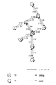
一般に、移動通信システムは移動端末(mobile element)と基地局(base station)間でデータを送受信する。すなわち、移動端末と基地局は他のノード(node)を経由せず直接データを送受信する。これに対して個人通信無線ネットワーク(wireless personal area network: WPAN)は、比較的に短距離内で少ないユーザ間で情報を伝達するために開発された。すなわち、WPANは多数個のノードが互いに通信できるようにするアドホック(ad−hoc)データ通信システムである。アドホックネットワークを構成している送信ノードは他のノードを用いて受信ノードにデータを転送する。送信ノードと受信ノードとが隣接している場合、データをノード間で直接伝達できる。以下、図1を用いてアドホックネットワークを構成しているノードで既存のアルゴリズムが行なうデータ送信について説明する。 2. Description of the Related Art Generally, a mobile communication system transmits and receives data between a mobile terminal and a base station. That is, the mobile terminal and the base station directly transmit and receive data without passing through another node. Wireless personal area networks (WPANs), on the other hand, have been developed to transfer information between relatively few users within a relatively short distance. That is, WPAN is an ad-hoc data communication system that allows a plurality of nodes to communicate with each other. The transmitting node configuring the ad hoc network transfers data to the receiving node using another node. If the transmitting node and the receiving node are adjacent, data can be transmitted directly between the nodes. Hereinafter, the data transmission performed by the existing algorithm in the nodes configuring the ad hoc network will be described with reference to FIG.
図1のアドホックネットワークは、少なくとも2つのノードで構成される。ノードはルーチンテーブルを保存しているノードとルーチンテーブルを保存しないノードとに区分される。以下、ルーチンテーブルを保存しているノードを「N+」とし、ルーチンテーブルを保存しないノードを「N−」と称する。 The ad hoc network of FIG. 1 includes at least two nodes. Nodes are classified into nodes storing the routine table and nodes not storing the routine table. Hereinafter, a node storing the routine table is referred to as “N +”, and a node not storing the routine table is referred to as “N−”.
以下、N+とN−で構成されたアドホックネットワークでルーチン経路を設定する過程について説明する。ノードAをソースノードと称し、ノードIを目的地ノードと称する。ソースノードはルーチン経路設定を要求するノードであり、目的地ノードはソースノードがルーチン経路を設定しようとするノードである。従って、ノードAはノードIにルーチン経路を設定するために、隣接しているノードBにルーチン経路設定要求(Route Request:RREQ)メッセージを転送する(S100)。N+であるノードBは、受信したRREQメッセージを用いてルーチンテーブルを生成し、生成したルーチンテーブルを保存する。RREQメッセージを受信したノードBは、隣接しているノードCとノードGにRREQメッセージを転送する(S102、S108)。N+であるノードCは、受信したRREQメッセージを用いてルーチンテーブルを生成し、生成したルーチンテーブルを保存する。RREQメッセージを受信したノードCは、隣接しているノードDとノードFにRREQメッセージを転送する(S104、S106)。 Hereinafter, a process of setting a routine route in an ad hoc network composed of N + and N− will be described. Node A is called a source node, and node I is called a destination node. The source node is a node that requests a routine route setting, and the destination node is a node that the source node intends to set a routine route. Therefore, the node A transfers a route request (Rout Request) message to the adjacent node B in order to set a routine route to the node I (S100). The node B, which is N +, generates a routine table using the received RREQ message, and stores the generated routine table. The node B receiving the RREQ message transfers the RREQ message to the adjacent nodes C and G (S102, S108). The node C that is N + generates a routine table using the received RREQ message, and stores the generated routine table. The node C that has received the RREQ message transfers the RREQ message to the adjacent nodes D and F (S104, S106).
RREQメッセージを受信したノードGは、RREQメッセージに対する応答であるルーチン経路設定応答(Route Reply:RREP)メッセージをノードBに転送する(S128)。既存のアルゴリズムによれば、アドホックネットワークを構成しているN−は受信したRREQメッセージについてRREPメッセージを転送する。すなわち、N−は受信されたRREQで要求する目的地ノードでなくてもRREPメッセージを転送する。それは、クラスタツリーの特性によって経路を探さなくても目的地ノード方向の次のホップノードが分かるからである。ノードGが転送したRREPメッセージは、ノードBを経てノードAに伝達される(S120)。RREPメッセージを転送したノードGは、隣接しているノードFにRREQメッセージを転送する(S104)。一般にN−はシステムに設計される所定距離(例えば1ホップ)以内のノードに対する情報を認知している。 The node G that has received the RREQ message transfers a Route Reply (RREP) message, which is a response to the RREQ message, to the node B (S128). According to the existing algorithm, the N- constituting the ad hoc network forwards the RREP message for the received RREQ message. That is, N- forwards the RREP message even if it is not the destination node requested in the received RREQ. This is because the next hop node in the direction of the destination node can be determined without searching for a route according to the characteristics of the cluster tree. The RREP message transferred by the node G is transmitted to the node A via the node B (S120). The node G that has transferred the RREP message transfers the RREQ message to the adjacent node F (S104). Generally, N- is aware of information for nodes within a predetermined distance (eg, one hop) designed for the system.
ノードDもノードGが行なった動作と同様な動作を行なう。従って、ノードDが生成したRREPメッセージは、ノードCとノードBを経てノードAに伝達される(S124、S122、S120)。ノードCまたはノードGからRREQメッセージを受信したノードFは、ノードEとノードHにRREQメッセージを転送する(S112、S114)。ノードEもノードGが行なう動作と同様な動作を行なう。ノードHは受信したRREQメッセージをノードIに伝達する(S116)。RREQメッセージを受信したノードIは、ノードAがルーチン経路を設定しようとするノードが自分であることを認知するようになる。従って、ノードIはRREQメッセージに対する応答であるRREPメッセージを生成する。生成されたRREPメッセージは、RREQメッセージが転送された経路を通してノードAに伝達される。前述したような過程を行なうことによってノードAとノードIとのルーチン経路が設定される。前述の説明で省略したが、ルーチンテーブルを保存するN+は、受信したRREQメッセージを更新した後隣接ノードに伝達する。一般に、N+は、ホップカウンタを更新した後隣接ノードに転送する。ホップカウンタが最も少ないルーチン経路がノード間のルーチン経路として選択される。前述したようにノードAは1つのRREQメッセージについて四つのRREPメッセージを受信するようになる。しかし、N−が転送したRREPメッセージは不要なメッセージである。 Node D performs the same operation as that performed by node G. Therefore, the RREP message generated by the node D is transmitted to the node A via the nodes C and B (S124, S122, S120). The node F receiving the RREQ message from the node C or the node G transfers the RREQ message to the nodes E and H (S112, S114). Node E performs the same operation as that performed by node G. The node H transmits the received RREQ message to the node I (S116). The node I that has received the RREQ message recognizes that the node A that the node A intends to set the routine route to is itself. Therefore, node I generates an RREP message that is a response to the RREQ message. The generated RREP message is transmitted to the node A through the path through which the RREQ message was transferred. By performing the above-described process, a routine route between the nodes A and I is set. Although omitted in the above description, the N + storing the routine table updates the received RREQ message and transmits it to the adjacent node. In general, N + updates the hop counter and then forwards it to neighboring nodes. The routine path with the smallest hop counter is selected as the routine path between the nodes. As described above, the node A receives four RREP messages for one RREQ message. However, the RREP message transferred by N- is an unnecessary message.
図2はアドホックネットワークを構成しているノードでルーチン経路を設定する他の例を示している。本例では既存の方法を使用した場合経路ループ問題が発生することを示す。ノードAとノードEとの間にルーチン経路が設定されたと仮定する。すなわち、ノードAに要求によってノードB、ノードC、ノードDを経由してノードEにルーチン経路が設定された。しかし、ノードDとノードEとの間の無線チャンネルが劣化し、図2に示されているように無線チャンネルが断絶される場合が発生する。この場合、ノードDは、ノードAにルーチンエラー(Routing Error: RERR)メッセージを転送する。RERRメッセージにはノードDとノードEとの間のルーチン経路が断絶されたことを意味する情報が含まれる。ノードDが転送したRERRメッセージはノードC、ノードBを経てノードAに伝達される。しかし、ノードAとノードBとの間、またはノードBとノードCとの間の無線チャンネルが一時的に劣化し、RERRメッセージがノードAに伝達されない場合が発生する。 FIG. 2 shows another example of setting a routine route in a node constituting an ad hoc network. This example shows that a route loop problem occurs when an existing method is used. Assume that a routine path has been set up between nodes A and E. That is, a routine route is set to the node E via the nodes B, C, and D at the request of the node A. However, the radio channel between the node D and the node E deteriorates, and a case occurs where the radio channel is disconnected as shown in FIG. In this case, the node D transfers a routing error (Routing Error: RERR) message to the node A. The RERR message includes information indicating that the routine path between the node D and the node E has been disconnected. The RERR message transferred by the node D is transmitted to the node A via the nodes C and B. However, the radio channel between the node A and the node B or between the node B and the node C may be temporarily degraded, and the RERR message may not be transmitted to the node A.
もしノードDがノードEに送信する新たなパケットが生成されたと仮定する。すると、ノードDがノードEにルーチン経路を設定しようとする場合、ノードDはノードCにRREQメッセージを転送する(S200)。ノードDはノードEにRREQメッセージを転送しても無線チャンネルが断絶されているため、ノードEはRREQメッセージを受信できなくなる。RREQメッセージを受信したノードFはノードAにRREQメッセージを転送する(S204)。この際、N−であるノードAはRREQを受信すると、ツリールート計算によってノードBを経て目的地ノードEに到達できることを認知し、ノードFにRREPメッセージを転送する(S210)。RREPメッセージを受信したノードFはノードCにRREPメッセージを転送する(S212)。RREP メッセージを受信したノードCはノードDにRREPメッセージを転送する(S214)。この際、ノードDがデータパケットを送る場合、データパケットの転送経路は、ノードD→ノードC→ノードF→ノードA→ノードB→ノードC→ノードDである。こうして設定した経路を利用する場合、データを転送できないことは自明である。また、不要なループを形成する結果を引き起こす。 Assume that a new packet has been created that node D sends to node E. Then, when the node D intends to set a routine route to the node E, the node D transfers an RREQ message to the node C (S200). Even if the node D transfers the RREQ message to the node E, the node E cannot receive the RREQ message because the radio channel is disconnected. The node F receiving the RREQ message transfers the RREQ message to the node A (S204). At this time, upon receiving the RREQ, the node A, which is N-, recognizes that the destination node E can be reached via the node B by the tree root calculation, and transfers an RREP message to the node F (S210). The node F receiving the RREP message transfers the RREP message to the node C (S212). The node C that has received the RREP message transfers the RREP message to the node D (S214). At this time, when the node D sends the data packet, the transfer route of the data packet is node D → node C → node F → node A → node B → node C → node D. When using the route set in this way, it is obvious that data cannot be transferred. It also results in the formation of unnecessary loops.
図3はアドホックネットワークを構成しているノードにおいてルーチン経路を設定するさらに他の例を示しているが、本例も既存のアルゴリズムを使用する場合、経路ループが生成され得ることを示している。ノードEはノードAとルーチン経路を設定しようとする。ノードEはノードDとノードFにRREQメッセージを転送する(S300、S302)。ノードDはノードCとノードGにRREQメッセージを転送する(S304、S308)。ノードFもノードGにRREQメッセージを転送する(S306)。ノードGはノードFにRREPメッセージを転送する(S330)。ノードFは受信したRREPをソースノードEに伝達する。これは、クラスタツリーを通してノードFを介してソースノードAを計算できるからである。RREQメッセージを受信したノードCは、ノードBにRREQメッセージを転送する(S310)。RREQメッセージを受信したノードBは、ノードAにRREQメッセージを転送する(S312)。RREQメッセージを受信したノードAは、ノードEがルーチン経路を設定しようとするノードが自分であることを認知するようになる。従って、ノードAはRREQメッセージに対する応答であるRREPメッセージを生成する。この生成されたRREPメッセージはノードBとノードCを経てノードDに伝達される(S320、S322、S324)。ノードDは伝達されたRREPメッセージをノードEに伝達する(S326)。問題はソースノードEが受信可能な2つのRREP(ノードA、ノードG)のうちノードGから先に受信する場合に発生する。この際、データパケットはノードD→ノードG→ノードF→ノードDに経路ループが発生するようになる。 FIG. 3 shows still another example of setting a routine path in a node constituting an ad hoc network. This example also shows that a path loop can be generated when an existing algorithm is used. Node E attempts to set up a routine path with node A. The node E transfers the RREQ message to the nodes D and F (S300, S302). The node D transfers the RREQ message to the nodes C and G (S304, S308). The node F also transfers the RREQ message to the node G (S306). The node G transfers the RREP message to the node F (S330). The node F transmits the received RREP to the source node E. This is because the source node A can be calculated via the node F through the cluster tree. The node C receiving the RREQ message transfers the RREQ message to the node B (S310). The node B receiving the RREQ message transfers the RREQ message to the node A (S312). The node A that has received the RREQ message becomes aware that the node to which the node E intends to set the routine route is itself. Therefore, node A generates an RREP message that is a response to the RREQ message. The generated RREP message is transmitted to the node D via the nodes B and C (S320, S322, S324). The node D transmits the transmitted RREP message to the node E (S326). The problem occurs when the source node E receives first from the receivable two RREPs (node A and node G) from the node G. At this time, the data packet causes a route loop from node D → node G → node F → node D.
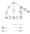
図4は、アドホックネットワークを構成しているノードでルーチン経路を設定するさらに他の例を示している。本例では既存のアルゴリズムを使用する場合、順方向経路と逆方向経路が相違に設定され得ることを示す。 FIG. 4 shows still another example of setting a routine route in nodes constituting an ad hoc network. This example shows that when an existing algorithm is used, the forward route and the reverse route can be set differently.
ノードAはノードEとルーチン経路を設定しようとする。ノードAは保存しているルーチンテーブルを検索して、ノードEとルーチン経路が設定されているか否かを判断する。その判断の結果、ノードEとルーチン経路が設定されていないので、ノードBにRREQメッセージを転送する(S400)。RREQメッセージを受信したノードBも保存しているルーチンテーブルを検索して、ノードEとルーチン経路が設定されているか否かを判断する。その判断の結果、ノードEとルーチン経路が設定されていないので、ノードCにRREQメッセージを転送する(S402)。 Node A attempts to establish a routing path with node E. The node A searches the stored routine table to determine whether or not the node E and the routine route are set. As a result of the determination, the RREQ message is transferred to the node B since the routine route has not been set with the node E (S400). The node B that has received the RREQ message also searches the stored routine table to determine whether the node E and the routine route are set. As a result of the determination, the RREQ message is transferred to the node C because the routine route with the node E is not set (S402).
ノードCは、ノードAがルーチン経路を設定しようとするノードが自分であるか否かを判断する。ノードAがルーチン経路を設定しようとするノードが自分でないので、ノードCは、クラスタツリールータに沿ってノードDにRREQメッセージを転送する(S404)。ノードDもノードAがルーチン経路を設定しようとするノードが自分であるか否かを判断する。ノードAがルーチン経路を設定しようとするノードが自分でないので、ノードDはノードEにRREQメッセージを転送する(S406)。ノードEは、ノードAがルーチン経路を設定しようとノードが自分であることを認知するようになる。 The node C determines whether the node to which the node A intends to set the routine route is itself. Since the node to which the node A is to set the routine route is not the node itself, the node C transfers the RREQ message to the node D along the cluster tree router (S404). Node D also determines whether the node to which node A is to set a routine route is itself. Node D forwards the RREQ message to node E because node A is not the node to which the routine path is to be set (S406). Node E becomes aware that node A is itself in order for node A to set up a routine path.
ノードEは、RREQメッセージに対する応答であるRREPメッセージを生成する。この生成されたRREPメッセージはノードDに伝達される(S410)。ノードDは伝達されたRREPメッセージをノードFに伝達する(S412)。ノードFはツリーに沿ってソースノードAに転送される。このように順方向(Forward)ルーチン経路と逆方向(Backward)ルーチン経路が相違になるという問題点を有する。従って、前述したような問題点を解決するための方策が論議される。 Node E generates an RREP message that is a response to the RREQ message. The generated RREP message is transmitted to the node D (S410). The node D transmits the transmitted RREP message to the node F (S412). Node F is forwarded along the tree to source node A. As described above, there is a problem that a forward routine path and a backward routine path are different. Therefore, measures for solving the above-mentioned problems are discussed.
本発明は前述した問題点を解決するために案出されたもので、本発明の目的は、RREQメッセージについて複数個のRREPメッセージが受信されることを防止する装置および方法を提供する。 The present invention has been devised to solve the above problems, and an object of the present invention is to provide an apparatus and a method for preventing a plurality of RREP messages from being received for an RREQ message.
本発明の他の目的は、ソースノードが設定されたルーチン経路の断絶の有無を迅速に判断できる装置および方法を提供する。 Another object of the present invention is to provide an apparatus and a method capable of quickly determining whether or not a set route is disconnected by a source node.
本発明のさらに他の目的は、経路ループを防止する装置および方法を提供する。 Still another object of the present invention is to provide an apparatus and a method for preventing a path loop.
本発明のさらに他の目的は、順方向ルーチン経路と同一な逆方向ルーチン経路を設定できる装置および方法を提供する。 Still another object of the present invention is to provide an apparatus and a method capable of setting the same reverse routine path as the forward routine path.
本発明のさらに他の目的は1つの目的地ノードについて最小ホップカウンタを有する1つのルーチン経路を設定する装置および方法を提供する。 Still another object of the present invention is to provide an apparatus and a method for setting one routine path having a minimum hop counter for one destination node.
前述した本発明の目的を達成するために、目的地ノードと該目的地ノードにルーチン経路を設定しようとするソースノードを含んだ複数個のノードで構成された移動通信システムにおいて、ルーチンテーブルを保存しない少なくとも1つのノードがソースノードから目的地ノードにルーチン経路設定を中継する方法において、伝達されたルーチン経路設定要求メッセージに含まれている情報を用いてルーチン経路設定要求メッセージを中継したノードに関する情報を保存し、隣接ノードにルーチン経路設定要求メッセージを伝達する段階、および伝達されたルーチン経路設定要求メッセージに対する応答メッセージを保存された情報を用いてルーチン経路設定を要求したノードに伝達する段階とから構成されることを特徴とする。 In order to achieve the above object of the present invention, a routine table is stored in a mobile communication system including a plurality of nodes including a destination node and a source node for setting a routine route to the destination node. In a method in which at least one node relays a routine path setting from a source node to a destination node, information about the node that relayed the routine path setting request message using information included in the transmitted routine path setting request message. Transmitting a routing request message to an adjacent node, and transmitting a response message to the transmitted routing request message to the node that has requested the routing using the stored information. It is characterized by comprising.
本発明の目的を達成するために目的地ノードと該目的地ノードにルーチン経路を設定しようとするソースノードを含んだ複数個のノードで構成された移動通信システムにおいて、ルーチンテーブルを保存しない少なくとも1つのノードを用いてソースノードから目的地ノードにルーチン経路設定するシステムにおいて、ルーチン経路設定要求メッセージを生成し、この生成されたルーチン経路設定要求メッセージを隣接ノードに伝達するソースノードと、伝達されたルーチン経路設定要求メッセージに含まれている情報を用いてルーチン経路設定要求メッセージを中継したノードに関する情報を保存し、伝達されたルーチン経路設定要求メッセージに対する応答メッセージを保存された情報を用いてルーチン経路設定を要求するルーチンテーブルを保存しない中継ノードとから構成されることを特徴とする。 In order to achieve the object of the present invention, in a mobile communication system including a plurality of nodes including a destination node and a source node for setting a routine route to the destination node, at least one of which does not store a routine table. In a system for setting a routine route from a source node to a destination node using one node, a source node for generating a route setting request message and transmitting the generated routing request message to an adjacent node; Using the information contained in the routine path setting request message, information about the node that relayed the routine path setting request message is stored, and a response message to the transmitted routine path setting request message is stored, and the routine path is stored using the stored information. Routine requesting setting Characterized in that it is composed of a relay node that does not store Le.
前述したように本願発明はN−が最小限の情報を保存し、この保存された情報を用いてルーチン経路を設定することによって順方向ルーチン経路と同一な逆方向ルーチン経路を設定できる。また、目的地ノードでだけRREPメッセージを転送することによって、複数個のRREPが生成されることを防止することができる。目的地ノードは設定されたルーチン経路を通して一定の時間間隔でソースノードにメッセージを転送することによりソースノードは設定されたルーチン経路の断絶の有無を迅速に認知できるようになる。 As described above, in the present invention, N- stores the minimum information and sets the routine path using the stored information, whereby the same reverse routine path as the forward routine path can be set. Further, by transferring the RREP message only at the destination node, generation of a plurality of RREPs can be prevented. The destination node transfers the message to the source node at regular time intervals through the set routine path, so that the source node can quickly recognize whether the set routine path is disconnected.
以下、図面を用いて本発明の実施例を詳述する。 Hereinafter, embodiments of the present invention will be described in detail with reference to the drawings.
図1において1つのRREQメッセージについて少なくとも2つのRREPメッセージが転送される場合について説明する。前述した問題点を解決するために、N−からRREPメッセージを転送する場合に制限を設けた。すなわち、N−は受信したRREQメッセージに含まれている目的地ノードが自分の場合にだけRREPメッセージを転送することができる。従って、図1を構成しているノードD、ノードE、ノードGはRREPメッセージを転送せず、ノードIだけがRREPメッセージを生成する。生成されたRREPメッセージはノードAに転送される。 A case where at least two RREP messages are transferred for one RREQ message in FIG. 1 will be described. In order to solve the above-mentioned problem, a restriction is provided when transferring an RREP message from N-. That is, N- can transmit the RREP message only when the destination node included in the received RREQ message is itself. Therefore, the nodes D, E, and G constituting FIG. 1 do not transfer the RREP message, and only the node I generates the RREP message. The generated RREP message is transferred to the node A.
図2においてアドホックネットワークでルーチン経路を設定するにおいてループが形成される場合について説明した。前述した問題点を解決するために、RERRメッセージを転送する代わりに、キープアライブ(keep−alive)メッセージを転送する。キープアライブメッセージは、ソースノードのアドレスと目的地ノードのアドレスを含む。図2を説明すれば、ノードAはソースノードであり、ノードEが目的地ノードである。ノードEはノードAにキープアライブメッセージを第1設定時間の間隔で転送する。第1設定時間はユーザの設定によって任意に調節することができる。アドホックネットワークを構成しているノード間の無線チャンネルが不良な場合は第1設定時間を短く設定する。しかし、アドホックネットワークを構成しているノード間の無線チャンネルが良好な場合は第1設定時間を長く設定する。ノードEは事前設定されたルーチン経路を用いてキープアライブメッセージを転送する。すなわち、ノードEはノードD、ノードC、ノードBを経てノードAにキープアライブメッセージを転送する。 In FIG. 2, the case where a loop is formed in setting a routine path in the ad hoc network has been described. In order to solve the above-mentioned problem, instead of transmitting the RERR message, a keep-alive message is transmitted. The keep-alive message contains the address of the source node and the address of the destination node. Referring to FIG. 2, node A is a source node, and node E is a destination node. Node E forwards the keep-alive message to node A at a first set time interval. The first set time can be arbitrarily adjusted according to a user setting. If the wireless channel between the nodes constituting the ad hoc network is defective, the first set time is set short. However, if the wireless channel between the nodes constituting the ad hoc network is good, the first setting time is set longer. Node E forwards the keep-alive message using a preset routine path. That is, the node E transfers the keep-alive message to the node A via the nodes D, C, and B.
ノードAは第2設定時間の間隔でノードBからキープアライブメッセージが受信されるか否かを判断する。一般に第2設定時間は第1設定時間より長く設定する。これは、ノードEが転送したキープアライブメッセージが無線チャンネルなどの影響によって遅延されノードAに伝達され得るからである。 Node A determines whether a keep-alive message is received from node B at a second set time interval. Generally, the second set time is set longer than the first set time. This is because the keep-alive message transmitted by the node E can be delayed and transmitted to the node A due to an influence of a radio channel or the like.
ノードAは第2設定時間以内にキープアライブメッセージが受信されるか否かを判断する。この判断の結果、第2設定時間以内にキープアライブメッセージが受信されれば、ノードAとノードEとのルーチン経路が正常であることを認知するようになる。しかし、第2設定時間以内にキープアライブメッセージが受信されなければ、ノードAとノードEとのルーチン経路にエラーが発生したことを認知するようになる。従って、ノードAはノードEにルーチン経路を再設定する。この場合、ルーチン経路再設定時間を短縮するために事前設定したルーチン経路を用いる。 Node A determines whether a keep-alive message is received within a second set time. As a result of this determination, if the keep-alive message is received within the second set time, it is recognized that the routine path between the nodes A and E is normal. However, if the keep-alive message is not received within the second set time, it is recognized that an error has occurred in the routine path between the nodes A and E. Therefore, node A resets the routine path to node E. In this case, a pre-set routine path is used to reduce the routine path reset time.
図5は本発明に係るソースノードで行なわれる動作を示した図である。以下、図5を用いて本発明に係るソースノードで行なわれる動作について詳述する。勿論、前述したように目的地ノードは第1設定時間の間隔でキープアライブメッセージを転送する。 FIG. 5 is a diagram showing an operation performed in the source node according to the present invention. Hereinafter, the operation performed in the source node according to the present invention will be described in detail with reference to FIG. Of course, as described above, the destination node transmits the keep-alive message at the first set time interval.
S500段階でソースノードは、目的地ノードに関する情報と目的地ノードに対応する第2設定時間を設定する。一般に、ソースノードは少なくとも2つの目的地ノードからキープアライブメッセージを受信する。しかし、図5では説明の便宜のため1つの目的地ノードからキープアライブメッセージを受信すると仮定する。 In operation S500, the source node sets information on the destination node and a second set time corresponding to the destination node. Generally, a source node receives keep-alive messages from at least two destination nodes. However, it is assumed in FIG. 5 that a keep-alive message is received from one destination node for convenience of explanation.
S502段階においてソースノードはカウントを開始する。S504段階においてソースノードは、第2設定時間内にキープアライブメッセージが受信されるか否かを判断する。この判断の結果、キープアライブメッセージが受信されればS508段階に移動し、判断の結果、キープアライブメッセージが受信されなければS506段階に移動する。S508段階においてソースノードはカウンタをリセットした後S502段階に移動する。S506段階においてソースノードは目的地ノードにルーチン経路を再設定する。前述したように、再設定するルーチン経路は事前設定されたルーチン経路を用いる。 In step S502, the source node starts counting. In operation S504, the source node determines whether a keep-alive message is received within a second set time. If it is determined that a keep-alive message has been received, the process proceeds to step S508. If the result of the determination is that a keep-alive message has not been received, the process proceeds to step S506. In step S508, the source node resets the counter and moves to step S502. In step S506, the source node resets a routine route to the destination node. As described above, the routine path to be reset uses a preset routine path.
図3および図4において記述した問題点を解決するため、本願発明はN−が最小限の情報を保存する方策を提案する。本発明の実施例において、RREQメッセージとRREPメッセージは必要な情報だけを含む。RREQメッセージは、ソースノードのアドレスとRREQ識別子(ID)と目的地ノードのアドレスとホップカウンタなどを含むことができる。RREPメッセージは、ソースノードの識別子と目的地ノードのアドレスとホップカウンタとルーチン経路上にあるN+の数などを含むことができる。ルーチン経路上にあるN+については後述する。 In order to solve the problems described in FIG. 3 and FIG. 4, the present invention proposes a measure for storing N-minimum information. In the embodiment of the present invention, the RREQ message and the RREP message include only necessary information. The RREQ message may include an address of the source node, an RREQ identifier (ID), an address of the destination node, a hop counter, and the like. The RREP message may include the identifier of the source node, the address of the destination node, the hop counter, the number of N + on the routine path, and the like. N + on the routine path will be described later.
下記の表1はN−で保存するルーチンテーブルの一例を示している。

表1を用いて図3のソースノードEは2つのRREPを受信するようになるが、ホップカウンタが小さい経路であるノードE→ノードD→ノードC→ノードB→ノードAを選択することにより、経路ループ問題を解決することができる。 Referring to Table 1, the source node E of FIG. 3 receives two RREPs. By selecting the node E → node D → node C → node B → node A, which is a path having a small hop counter, The path loop problem can be solved.
以下、図6に基づき順方向ルーチン経路と逆方向ルーチン経路が同じく設定される過程について説明する。 Hereinafter, a process in which the forward routine path and the reverse routine path are set similarly will be described with reference to FIG.
ノードAはノードEとルーチン経路を設定しようとする。ノードAからノードEにRREQメッセージが転送される過程は図4で説明した通りである。以下、ノードEからノードAにRREPメッセージを転送する過程について説明する。 Node A attempts to establish a routing path with node E. The process of transferring the RREQ message from the node A to the node E is as described with reference to FIG. Hereinafter, a process of transferring the RREP message from the node E to the node A will be described.
ノードEはRREQメッセージに対する応答であるRREPメッセージを生成する。生成されたRREPメッセージはノードDに伝達される(S410)。ノードDは保存されているルーチンテーブルを用いて、RREPに対応するRREQメッセージがノードCから伝達されたことを認知する。従って、ノードDはノードCにRREPメッセージを転送する(S414)。ノードCは保存されているルーチンテーブルを用いて、RREPに対応するRREQメッセージがノードBから伝達されたことを認知する。従って、ノードCはノードBにRREPメッセージを転送する(S416)。ノードBは保存されているルーチンテーブルを用いて、ノードAにRREPメッセージを転送する(S418)。前述したように、N−で最小限の情報を保存することによって順方向ルーチン経路と逆方向ルーチン経路を同じく設定できるようになる。 Node E generates an RREP message that is a response to the RREQ message. The generated RREP message is transmitted to the node D (S410). The node D recognizes that the RREQ message corresponding to the RREP has been transmitted from the node C using the stored routine table. Therefore, the node D transfers the RREP message to the node C (S414). The node C uses the stored routine table to recognize that the RREQ message corresponding to the RREP has been transmitted from the node B. Therefore, the node C transfers the RREP message to the node B (S416). The node B transfers the RREP message to the node A using the stored routine table (S418). As described above, by storing the minimum information in N-, the forward routine path and the reverse routine path can be set in the same manner.
前述の方策の他、RREPメッセージにボーダー(border)ノードに関する情報を含め、情報を利用する方策がある。ボーダーノードは相異なるツリールートに位置しているノードを連結するノードを意味する。図6によれば、ツリールートはノードFからノードAまで、ノードFからノードBまで、ノードFからノードCまたはEまでのルートを意味する。順方向ルーチン経路を設定する場合、ノードA、ノードB、ノードCは相異なるツリールートに位置しているノードである。従って、RREPメッセージにボーダーノードに関する情報を含める。ノードEは生成されたRREPメッセージをノードDに転送し(S410)、ノードDは伝達されたRREPメッセージに含まれているノードCに対する情報を獲得する。この獲得された情報を用いてRREPメッセージをノードCに転送する(S414)。ノードCも伝達されたRREPメッセージに含まれているノードBに対する情報を獲得する。この獲得された情報を用いてRREPメッセージをノードBに転送する(S416)。ノードCは保存されているルーチンテーブルを用いたり、RREPメッセージに含まれている情報を用いて、伝達されたRREPメッセージをノードAに転送する(S418)。前述の説明では省略したが、RREPメッセージを受信した各ノードは、受信したRREPメッセージを更新した後隣接ノードに転送する。 In addition to the above-described measures, there is a method of using information by including information on a border node in the RREP message. A border node refers to a node that connects nodes located at different tree roots. According to FIG. 6, the tree root means the root from node F to node A, from node F to node B, from node F to node C or E. When setting a forward routine path, nodes A, B, and C are nodes located at different tree roots. Therefore, the information about the border node is included in the RREP message. The node E transfers the generated RREP message to the node D (S410), and the node D acquires information on the node C included in the transmitted RREP message. The RREP message is transferred to the node C using the obtained information (S414). The node C also obtains information on the node B included in the transmitted RREP message. The RREP message is transferred to the node B using the obtained information (S416). The node C transfers the transmitted RREP message to the node A using the stored routine table or using the information included in the RREP message (S418). Although omitted in the above description, each node that has received the RREP message updates the received RREP message and then transfers it to an adjacent node.
RREPメッセージにルーチン経路上のN+の個数を含む理由は、1つの目的地ノードについて少なくとも2つのルーチン経路が設定された場合、N+が多い経路にデータを転送するためである。これは、N+がN−よりエラー発生確率が低いからである。 The reason that the RREP message includes the number of N + on the routine path is that when at least two routine paths are set for one destination node, data is transferred to the path with more N +. This is because N + has a lower error occurrence probability than N−.
以上本発明の好ましい実施形態について説明しているが、本発明は前述した特定の実施形態に限られず、請求の範囲で請求する本発明の要旨を逸脱せず当該発明の属する技術分野において通常の知識を持つ者ならば誰でも多様な変形実施が可能なことは勿論、そのような変更は請求の範囲の記載内にある。 Although the preferred embodiments of the present invention have been described above, the present invention is not limited to the specific embodiments described above, and does not depart from the gist of the present invention claimed in the claims. Various modifications can be made by anyone with knowledge, and such modifications are within the scope of the claims.
A ソースノード
E 目的地ノード
I 目的地ノード
A Source node E Destination node I Destination node
Claims (13)
伝達されたルーチン経路設定要求メッセージに含まれている情報を用いて前記ルーチン経路設定要求メッセージを中継したノードに関する情報を保存し、隣接するノードに前記ルーチン経路設定要求メッセージを伝達する段階と、
伝達された前記ルーチン経路設定要求メッセージに対する応答メッセージを、保存された前記情報を用いてルーチン経路設定を要求したノードに伝達する段階とを備えることを特徴とするルーチン経路を設定する方法。 In a mobile communication system including a plurality of nodes including a destination node and a source node for setting a route route to the destination node, at least one node that does not store a routing table is transmitted from the source node to the destination node. In a method of setting a routine route to a node,
Storing information on a node that relayed the routine path setting request message using information included in the transmitted routine path setting request message, and transmitting the routine path setting request message to an adjacent node;
Transmitting a response message to the transmitted routing request message to the node that has requested the routing using the stored information.
ルーチン経路設定要求メッセージを生成し、該生成されたルーチン経路設定要求メッセージを隣接するノードに伝達するソースノードと、
伝達された前記ルーチン経路設定要求メッセージに含まれている情報を用いて前記ルーチン経路設定要求メッセージを中継したノードに関する情報を保存し、伝達された前記ルーチン経路設定要求メッセージに対する応答メッセージを、保存された前記情報を用いてルーチン経路設定を要求する、ルーチンテーブルを保存しない中継ノードとを備えることを特徴とするルーチン経路設定システム。 In a mobile communication system including a destination node and a plurality of nodes including a source node for setting a routine route to the destination node, the mobile node uses at least one node that does not store a routine table to transmit data from the source node. In a routine route setting system for setting a routine route to the destination node,
A source node that generates a routine path setting request message and transmits the generated routine path setting request message to an adjacent node;
The information about the node that relayed the routine path setting request message is stored using the information included in the transmitted routine path setting request message, and a response message to the transmitted routine path setting request message is stored. And a relay node that does not store a routine table and requests a routine path setting using the information.
The source node, when there are two or more routine routes set for the destination node, uses a routine route having a large number of nodes to store a routine table that constitutes the set routine route. 8. The routing system of claim 7, wherein the transfer is performed.
Applications Claiming Priority (2)
| Application Number | Priority Date | Filing Date | Title |
|---|---|---|---|
| US46755503P | 2003-05-05 | 2003-05-05 | |
| KR1020040013117A KR100645428B1 (en) | 2003-05-05 | 2004-02-26 | Apparatus and method for establishment of routing path in wpan |
Related Child Applications (1)
| Application Number | Title | Priority Date | Filing Date |
|---|---|---|---|
| JP2006228063A Division JP2006314147A (en) | 2003-05-05 | 2006-08-24 | Routing system in wireless personal communication network and method thereof |
Publications (1)
| Publication Number | Publication Date |
|---|---|
| JP2004336786A true JP2004336786A (en) | 2004-11-25 |
Family
ID=32993179
Family Applications (2)
| Application Number | Title | Priority Date | Filing Date |
|---|---|---|---|
| JP2004137339A Pending JP2004336786A (en) | 2003-05-05 | 2004-05-06 | Apparatus and method for setting up routine path in personal communication wireless network |
| JP2006228063A Pending JP2006314147A (en) | 2003-05-05 | 2006-08-24 | Routing system in wireless personal communication network and method thereof |
Family Applications After (1)
| Application Number | Title | Priority Date | Filing Date |
|---|---|---|---|
| JP2006228063A Pending JP2006314147A (en) | 2003-05-05 | 2006-08-24 | Routing system in wireless personal communication network and method thereof |
Country Status (3)
| Country | Link |
|---|---|
| EP (1) | EP1475926B1 (en) |
| JP (2) | JP2004336786A (en) |
| CN (1) | CN1602077B (en) |
Families Citing this family (10)
| Publication number | Priority date | Publication date | Assignee | Title |
|---|---|---|---|---|
| US7668173B2 (en) * | 2005-12-01 | 2010-02-23 | Azalea Networks | Method and system for an adaptive wireless routing protocol in a mesh network |
| KR100713626B1 (en) | 2006-06-19 | 2007-05-02 | 삼성전자주식회사 | Motile communication terminal for providing ad-hoc network service and method for managing ad-hoc network using the same |
| CN101388831B (en) * | 2007-09-14 | 2011-09-21 | 华为技术有限公司 | Data transmission method, node and gateway |
| CN101437045B (en) * | 2008-12-18 | 2012-04-25 | 腾讯科技(深圳)有限公司 | Method for selecting transfer node of P2P system and P2P node |
| JP5424818B2 (en) * | 2009-10-30 | 2014-02-26 | 三菱電機株式会社 | Route control method, node, and communication system |
| CN101741547B (en) * | 2009-12-18 | 2012-05-23 | 西安西电捷通无线网络通信股份有限公司 | Inter-node secret communication method and system |
| CN101854306B (en) | 2010-06-07 | 2011-12-28 | 西安西电捷通无线网络通信股份有限公司 | Exchange routing search method and system |
| US8667172B2 (en) * | 2011-06-07 | 2014-03-04 | Futurewei Technologies, Inc. | Method and apparatus for content identifier based radius constrained cache flooding to enable efficient content routing |
| CN106803805B (en) * | 2015-11-26 | 2021-02-12 | 华为技术有限公司 | Method and device for solving message circuity in Diameter network |
| CN107819679B (en) * | 2016-09-13 | 2021-04-20 | 中兴通讯股份有限公司 | Method, device and system for forwarding flow message |
Family Cites Families (4)
| Publication number | Priority date | Publication date | Assignee | Title |
|---|---|---|---|---|
| US5987011A (en) * | 1996-08-30 | 1999-11-16 | Chai-Keong Toh | Routing method for Ad-Hoc mobile networks |
| FI101922B (en) * | 1997-01-03 | 1998-09-15 | Nokia Telecommunications Oy | Directing response to short message |
| US6507589B1 (en) * | 1998-04-30 | 2003-01-14 | Openwave Systems Inc. | Method and apparatus for routing between network gateways and service centers |
| WO2002084956A1 (en) * | 2001-04-16 | 2002-10-24 | Kent Ridge Digital Labs | A routing protocol for general mobile ad hoc networks |
-
2004
- 2004-05-03 EP EP04010463A patent/EP1475926B1/en active Active
- 2004-05-05 CN CN200410047771.2A patent/CN1602077B/en active Active
- 2004-05-06 JP JP2004137339A patent/JP2004336786A/en active Pending
-
2006
- 2006-08-24 JP JP2006228063A patent/JP2006314147A/en active Pending
Also Published As
| Publication number | Publication date |
|---|---|
| EP1475926A2 (en) | 2004-11-10 |
| EP1475926A3 (en) | 2007-02-28 |
| JP2006314147A (en) | 2006-11-16 |
| CN1602077B (en) | 2010-05-26 |
| EP1475926B1 (en) | 2009-04-22 |
| CN1602077A (en) | 2005-03-30 |
Similar Documents
| Publication | Publication Date | Title |
|---|---|---|
| JP5084405B2 (en) | Loop-free ad hoc routing system | |
| JP2006314147A (en) | Routing system in wireless personal communication network and method thereof | |
| US8441958B2 (en) | Directed acyclic graph discovery and network prefix information distribution relative to a clusterhead in an ad hoc mobile network | |
| KR101256687B1 (en) | Apparatus for setting multipath and method thereof | |
| US8064416B2 (en) | Route selection in wireless networks | |
| KR100645428B1 (en) | Apparatus and method for establishment of routing path in wpan | |
| US7450521B2 (en) | Cost-based routing using backoff scheme | |
| KR100810662B1 (en) | Method and apparatus for discoverying route in a wireless network | |
| US20050036486A1 (en) | Route discovery in ad-hoc networks with data packets | |
| JP2005168020A (en) | Communication path control method and communication terminal for radio multi-hop network | |
| US8213352B2 (en) | Wireless communication system, wireless communication device, wireless communication method, and program | |
| JP4918900B2 (en) | Wireless multi-hop network, node, multicast routing method and program | |
| JP2006211375A (en) | Load distribution method in wireless ad hoc network | |
| JP4627465B2 (en) | Wireless communication terminal and QoS information collecting method | |
| KR101083391B1 (en) | Method for transmitting data from a transmission vehicle to a destination vehicle in vehicle Ad-hoc network | |
| KR101452613B1 (en) | P2P routing method in mobile Ad-hoc network | |
| JP4297347B2 (en) | Ad hoc wireless network route establishment method and wireless node | |
| Clausen | Combining temporal and spatial partial topology for MANET routing-merging OLSR and FSR | |
| EP1883184A1 (en) | Method and apparatus for routing a message | |
| JP4772019B2 (en) | Wireless communication apparatus and wireless communication system | |
| KR100902290B1 (en) | Apparatus and method for establishment of routing path in wpan | |
| KR101349061B1 (en) | Method for routing in mobile ad-hoc network | |
| KR20170081904A (en) | Method and apparatus for operating network | |
| KR20100068153A (en) | Path setting apparatus and method based on attributes of an ad-hoc network | |
| KR100597409B1 (en) | Method and apparatus for configuring routing path in a mobile ad hoc network |
Legal Events
| Date | Code | Title | Description |
|---|---|---|---|
| A521 | Request for written amendment filed |
Free format text: JAPANESE INTERMEDIATE CODE: A821 Effective date: 20040723 |
|
| A521 | Request for written amendment filed |
Free format text: JAPANESE INTERMEDIATE CODE: A523 Effective date: 20041008 |
|
| A977 | Report on retrieval |
Free format text: JAPANESE INTERMEDIATE CODE: A971007 Effective date: 20060522 |
|
| A131 | Notification of reasons for refusal |
Free format text: JAPANESE INTERMEDIATE CODE: A131 Effective date: 20060524 |
|
| A521 | Request for written amendment filed |
Free format text: JAPANESE INTERMEDIATE CODE: A523 Effective date: 20060824 |
|
| A131 | Notification of reasons for refusal |
Free format text: JAPANESE INTERMEDIATE CODE: A131 Effective date: 20070404 |
|
| A521 | Request for written amendment filed |
Free format text: JAPANESE INTERMEDIATE CODE: A523 Effective date: 20070704 |
|
| A02 | Decision of refusal |
Free format text: JAPANESE INTERMEDIATE CODE: A02 Effective date: 20080311 |
|
| A521 | Request for written amendment filed |
Free format text: JAPANESE INTERMEDIATE CODE: A523 Effective date: 20080711 |
|
| A521 | Request for written amendment filed |
Free format text: JAPANESE INTERMEDIATE CODE: A523 Effective date: 20080714 |