JP2004336734A - Wireless terminal, base apparatus, wireless system, control method of wireless terminal, control program of wireless terminal, and computer-readable recording medium for recording the same - Google Patents
Wireless terminal, base apparatus, wireless system, control method of wireless terminal, control program of wireless terminal, and computer-readable recording medium for recording the same Download PDFInfo
- Publication number
- JP2004336734A JP2004336734A JP2004118359A JP2004118359A JP2004336734A JP 2004336734 A JP2004336734 A JP 2004336734A JP 2004118359 A JP2004118359 A JP 2004118359A JP 2004118359 A JP2004118359 A JP 2004118359A JP 2004336734 A JP2004336734 A JP 2004336734A
- Authority
- JP
- Japan
- Prior art keywords
- video
- data
- wireless terminal
- wireless
- unit
- Prior art date
- Legal status (The legal status is an assumption and is not a legal conclusion. Google has not performed a legal analysis and makes no representation as to the accuracy of the status listed.)
- Pending
Links
Images


Classifications
-
- H—ELECTRICITY
- H04—ELECTRIC COMMUNICATION TECHNIQUE
- H04N—PICTORIAL COMMUNICATION, e.g. TELEVISION
- H04N21/00—Selective content distribution, e.g. interactive television or video on demand [VOD]
- H04N21/40—Client devices specifically adapted for the reception of or interaction with content, e.g. set-top-box [STB]; Operations thereof
- H04N21/43—Processing of content or additional data, e.g. demultiplexing additional data from a digital video stream; Elementary client operations, e.g. monitoring of home network or synchronising decoder's clock; Client middleware
- H04N21/431—Generation of visual interfaces for content selection or interaction; Content or additional data rendering
- H04N21/4312—Generation of visual interfaces for content selection or interaction; Content or additional data rendering involving specific graphical features, e.g. screen layout, special fonts or colors, blinking icons, highlights or animations
- H04N21/4316—Generation of visual interfaces for content selection or interaction; Content or additional data rendering involving specific graphical features, e.g. screen layout, special fonts or colors, blinking icons, highlights or animations for displaying supplemental content in a region of the screen, e.g. an advertisement in a separate window
-
- H—ELECTRICITY
- H04—ELECTRIC COMMUNICATION TECHNIQUE
- H04N—PICTORIAL COMMUNICATION, e.g. TELEVISION
- H04N5/00—Details of television systems
- H04N5/44—Receiver circuitry for the reception of television signals according to analogue transmission standards
- H04N5/445—Receiver circuitry for the reception of television signals according to analogue transmission standards for displaying additional information
- H04N5/45—Picture in picture, e.g. displaying simultaneously another television channel in a region of the screen
-
- H—ELECTRICITY
- H04—ELECTRIC COMMUNICATION TECHNIQUE
- H04H—BROADCAST COMMUNICATION
- H04H20/00—Arrangements for broadcast or for distribution combined with broadcast
- H04H20/65—Arrangements characterised by transmission systems for broadcast
- H04H20/71—Wireless systems
-
- H—ELECTRICITY
- H04—ELECTRIC COMMUNICATION TECHNIQUE
- H04N—PICTORIAL COMMUNICATION, e.g. TELEVISION
- H04N21/00—Selective content distribution, e.g. interactive television or video on demand [VOD]
- H04N21/40—Client devices specifically adapted for the reception of or interaction with content, e.g. set-top-box [STB]; Operations thereof
- H04N21/47—End-user applications
- H04N21/482—End-user interface for program selection
- H04N21/4821—End-user interface for program selection using a grid, e.g. sorted out by channel and broadcast time
Abstract
Description
本発明は、無線端末、ベース機器、ワイヤレスシステム、無線端末の制御方法、無線端末の制御プログラム、およびそれを記録したコンピュータ読み取り可能な記録媒体に関する。 The present invention relates to a wireless terminal, a base device, a wireless system, a method for controlling a wireless terminal, a control program for a wireless terminal, and a computer-readable recording medium that records the program.
近年、映像及び音声等の受信・再生システム(AVシステム)において、映像を再生(表示)するためのモニタ部として薄型の液晶表示装置を用いたものが多く開発されている。液晶表示装置を用いると、大画面の表示も可能であるにもかかわらず、表示装置自体を軽量かつ薄型にすることができるという大きな利点がある。 2. Description of the Related Art In recent years, in a receiving / reproducing system (AV system) for video and audio, many monitors using a thin liquid crystal display device as a monitor unit for reproducing (displaying) video have been developed. The use of the liquid crystal display device has a great advantage in that the display device itself can be reduced in weight and thickness, even though a large screen can be displayed.
さらに、テレビ受像器のチューナ部(ベース機器)とモニタ部(無線端末)とを分離し、チューナ部からモニタ部に映像信号と音声信号とをワイヤレス伝送するシステムが開示されている。このシステムにおいては、分離したチューナ部にアンテナ線を接続して選局し、その選局した映像と音声信号をモニタ部にワイヤレス伝送して映像と音声信号を再生することができる(例えば特許文献1、2参照)。
また、テレビ受像器のチューナ部とモニタ部とを分離してワイヤレスで接続された上記システムにおいて、GUI(graphical user interface,グラフィック・ユーザ・インターフェイス)をモニタ部に表示させ、利用者が上記GUIによってシステムを操作できるものがある。具体的に説明すると、モニタ側でGUIを操作するためのキー入力を行い、GUI開始/終了、カーソル上/下/左/右キーなどをワイヤレス伝送に用いられるコマンドに変換する。チューナ側でGUI開始/終了、カーソル上/下/左/右キーに関連するコマンドを受け取ってこれをデコードし、チューナ側でGUIを生成するOSD機能を活用して出力し、GUI映像を含む映像信号(ビデオ信号)をワイヤレスAV伝送の送信部に出力し、AVストリームに変換してモニタ側に出力する。モニタ側でこれを受け取り、GUI映像を含む映像信号をデコードしてモニタに表示する。 Further, in the above system in which the tuner section and the monitor section of the television receiver are separated and wirelessly connected, a GUI (graphical user interface) is displayed on the monitor section, and the user uses the GUI to display the GUI. Some can operate the system. More specifically, key input for operating the GUI is performed on the monitor side, and GUI start / end, cursor up / down / left / right keys, etc. are converted into commands used for wireless transmission. The tuner receives and decodes commands related to the start / end of the GUI and the cursor up / down / left / right keys and outputs them using the OSD function of generating a GUI on the tuner, and outputs images including GUI images. The signal (video signal) is output to a transmission unit of wireless AV transmission, converted into an AV stream, and output to a monitor. The monitor receives this, decodes the video signal containing the GUI video, and displays it on the monitor.
上記システムにおいては、チューナ側でOSDを重畳した形でMPEG2形式にエンコードしモニタ側に送る。モニタ側でこのエンコード信号をデコードしてモニタ部に表示するため、MPEG2へのエンコード時間とデコードする時間とにより遅延が発生しOSD入力に対する表示レスポンスが悪くなること、GUI表示品位が劣化するという問題があった。 In the above system, the tuner side encodes the data in the MPEG2 format with the OSD superimposed and sends it to the monitor side. Since the monitor side decodes this encoded signal and displays it on the monitor unit, a delay occurs due to the encoding time to MPEG2 and the decoding time, so that the display response to the OSD input deteriorates and the GUI display quality deteriorates. was there.
この問題について、さらに詳細に説明する。以上のシステムにおいて、モニタ部は、利用者からのGUI映像表示の指示を入力すると、GUI映像の表示の要求コマンドをチューナ部へ送信する。この要求コマンドを受けたチューナ部は、上記のGUI映像の生成処理を行う。そして、チューナ部は、テレビ放送に関する映像信号に上記のGUI映像のデータを重畳し、重畳した映像信号をMPEG2形式でエンコードし、このエンコードした信号をモニタ部へ送信する。さらに、モニタ部は、チューナ部から受信するエンコードされた信号をデコードし、テレビ放送の映像上にGUI映像を重畳した映像を表示する。 This problem will be described in more detail. In the above system, upon input of a GUI image display instruction from a user, the monitor unit transmits a GUI image display request command to the tuner unit. The tuner unit that has received this request command performs the above-described GUI video generation processing. Then, the tuner unit superimposes the GUI video data on the video signal related to the television broadcast, encodes the superimposed video signal in the MPEG2 format, and transmits the encoded signal to the monitor unit. Further, the monitor unit decodes the encoded signal received from the tuner unit, and displays an image in which a GUI image is superimposed on a television broadcast image.
以上のシステムでは、チューナ部側においてテレビ放送の映像上にGUI映像を重畳している。したがって、テレビ放送の映像上にGUI映像を重畳した映像の信号をエンコードして送信し、モニタ側において、このエンコードされたデータを受信してデコードするという手順が必要になる。ここで、テレビ放送用の映像に対してGUI映像を重畳し、重畳した映像のデータをエンコード、デコードする場合、単にテレビ放送用の映像のデータをエンコード・デコードする場合よりも、データの送信が大幅に遅延する。したがって、以上のシステムでは、利用者からの指示の入力に対するGUI映像表示のレスポンスが悪化するという問題が生じていた。また、以上のシステムでは、チューナ部とモニタ部との間において通信状態が悪化すると、モニタ部において表示されるテレビ放送用の映像が劣化するが、これと共に重畳されるGUI映像も劣化してしまうという問題が生じていた。 In the above system, the GUI image is superimposed on the television broadcast image on the tuner section side. Therefore, it is necessary to perform a procedure of encoding and transmitting a video signal in which a GUI video is superimposed on a television broadcast video, and receiving and decoding the encoded data on the monitor side. Here, when the GUI video is superimposed on the video for television broadcasting, and the data of the superimposed video is encoded and decoded, the data transmission is performed more simply than when the data of the video for television broadcasting is simply encoded and decoded. Significantly delayed. Therefore, the above system has a problem that the response of the GUI image display to the input of the instruction from the user is deteriorated. Further, in the above system, when the communication state between the tuner unit and the monitor unit deteriorates, the television broadcast image displayed on the monitor unit deteriorates, and the superimposed GUI image also deteriorates. The problem had arisen.
本発明は、以上の問題に鑑みてなされたものであり、第一の映像に第二の映像を重畳して表示部に表示する際のレスポンスの悪化を抑制する無線端末、ベース機器、ワイヤレスシステム、無線端末の制御方法、無線端末の制御プログラム、およびそれを記録したコンピュータ読み取り可能な記録媒体を提供することを目的とする。 The present invention has been made in view of the above problems, and a wireless terminal, a base device, and a wireless system that suppress deterioration of a response when a second image is superimposed on a first image and displayed on a display unit It is an object of the present invention to provide a wireless terminal control method, a wireless terminal control program, and a computer-readable recording medium recording the same.
上記目的を達成するために、本発明の無線端末は、ベース機器との間でデータの送受信を行う無線端末であって、ベース機器から、第一の映像のデータと、上記ベース機器および/または無線端末に関連する関連データとを受信する受信手段と、上記第一の映像のデータに基づいて第一の映像を生成する第一映像生成手段と、上記関連データに基づいて第二の映像を生成する第二映像生成手段と、上記第一の映像に対して第二の映像を重畳し、重畳した映像を表示部に表示する映像重畳手段と、を含むことを特徴とする。 In order to achieve the above object, a wireless terminal of the present invention is a wireless terminal that transmits and receives data to and from a base device, and from the base device, data of a first video, and the base device and / or Receiving means for receiving relevant data related to the wireless terminal, first video generating means for generating a first video based on the data of the first video, and a second video based on the relevant data It is characterized by including a second video generating means for generating, and a video superimposing means for superimposing a second video on the first video and displaying the superimposed video on a display unit.
また、上記の目的を達成するために、本発明の無線端末の制御方法は、ベース機器との間でデータの送受信を行う無線端末の制御方法であって、ベース機器から、第一の映像のデータと、上記ベース機器および/または無線端末に関連する関連データとを受信するステップと、上記第一の映像のデータに基づいて第一の映像を生成するステップと、上記関連データに基づいて第二の映像を生成するステップと、上記第一の映像に対して第二の映像を重畳し、重畳した映像を表示部に表示するステップと、を含むことを特徴とする。 Further, in order to achieve the above object, a wireless terminal control method of the present invention is a wireless terminal control method for transmitting and receiving data to and from a base device. Receiving data and related data associated with the base device and / or wireless terminal; generating a first video based on the data of the first video; Generating a second video; and superimposing the second video on the first video, and displaying the superimposed video on a display unit.
上記構成によれば、ベース機器から第一の映像のデータを受信し、上記第一の映像のデータに基づいて第一の映像を生成すると共に、ベース機器から上記関連データを受信し、上記関連データに基づいて第二の映像を生成している。さらに、上記第一の映像に対して第二の映像を重畳し、重畳した映像を表示部に表示している。つまり、上記構成によれば、第二の映像の生成処理、および第一の映像と第二の映像との重畳処理を無線端末にて実施している。したがって、上記構成によれば、これらの処理をベース機器側で行っている従来の構成と比べ、重畳した映像のデータをエンコード・デコードする必要がないため、第一の映像と第二の映像とを重畳した映像の表示に関し、利用者の指示の入力に対する応答速度を向上できる。 According to the configuration, the first video data is received from the base device, the first video is generated based on the first video data, and the related data is received from the base device. A second image is generated based on the data. Further, the second video is superimposed on the first video, and the superimposed video is displayed on the display unit. That is, according to the above configuration, the generation processing of the second video and the superimposition processing of the first video and the second video are performed by the wireless terminal. Therefore, according to the above configuration, compared to the conventional configuration in which these processes are performed on the base device side, there is no need to encode and decode the superimposed video data, so that the first video and the second video are With respect to the display of a video on which is superimposed, the response speed to the input of the user's instruction can be improved.
なお、上記の第一の映像には、上記ベース機器が受信するテレビ放送の映像、ビデオデッキまたはDVD(Digital Versatile Disc)レコーダから再生される映像が含まれる。また、テレビ放送用の映像には、地上波アナログ放送、地上波デジタル放送のテレビ映像のみならず、衛星放送の映像、データ放送の映像、CATV放送を受信したセットトップボックスから出力される映像(CATV放送の映像)も含まれる。また、上記の関連データには、例えば、ベース機器および/または無線端末の設定状態を示すデータ、ベース機器が受信するテレビ放送に関するデータ(例えば、EPGデータ)等が含まれる。また、上記の第二の映像には、上記ベース機器および/または無線端末を操作するためのGUI映像、上記ベース機器および/または無線端末の設定状態を示した画像、EPG(Electronic Program Guide)映像等がある。 Note that the first video includes a video of a television broadcast received by the base device and a video reproduced from a VCR or a DVD (Digital Versatile Disc) recorder. In addition, TV broadcast video includes not only terrestrial analog broadcast and terrestrial digital broadcast TV video but also satellite broadcast video, data broadcast video, and video output from a set-top box that has received CATV broadcast ( CATV broadcast video). The related data includes, for example, data indicating a setting state of the base device and / or the wireless terminal, data related to television broadcast received by the base device (eg, EPG data), and the like. The second video includes a GUI video for operating the base device and / or the wireless terminal, an image showing a setting state of the base device and / or the wireless terminal, an EPG (Electronic Program Guide) video. Etc.
本発明の無線端末は、上記構成に加えて、上記受信手段が受信する上記関連データを記憶する記憶部を含み、上記第二映像生成手段は、上記記憶部に記憶されている関連データに基づいて、第二の映像を生成することを特徴とする。 In addition to the above configuration, the wireless terminal of the present invention includes a storage unit that stores the related data received by the receiving unit, and the second video generation unit performs processing based on the related data stored in the storage unit. And generating a second video.
上記構成によれば、ベース機器から受信した関連データは記憶部に記憶されることになる。従って、利用者から上記重畳した映像を表示する指示が入力された時点で、既に関連データが記憶部に記憶されていれば、直ぐに第二の映像を生成できる。 According to the above configuration, the related data received from the base device is stored in the storage unit. Therefore, when the user inputs an instruction to display the superimposed video, the second video can be generated immediately if the related data is already stored in the storage unit.
なお、無線端末とベース機器との間で通信状態が悪化しても、利用者から上記重畳した映像を表示する指示が入力された時点で既に記憶部に関連データが記憶されていれば、悪化した通信状態の影響を受けずに第二の映像を生成することができ、第二の映像を劣化させることなく表示部に表示させることができる。 In addition, even if the communication state between the wireless terminal and the base device deteriorates, if the related data is already stored in the storage unit when the user inputs an instruction to display the superimposed video, the deterioration may occur. The second video can be generated without being affected by the communication state, and can be displayed on the display unit without deteriorating the second video.
本発明の無線端末は、上記構成に加えて、上記第二映像生成手段は、上記無線端末が保持するテンプレートデータに対して上記関連データを付加することにより第二の映像を生成することを特徴とする。 In the wireless terminal according to the present invention, in addition to the above configuration, the second video generating means generates a second video by adding the relevant data to template data held by the wireless terminal. And
上記構成によれば、第二の映像とは、テンプレートデータ(定型データ)に対して上記関連データを付加することにより生成されるものであるため、第二の映像には定型箇所と非定型箇所とがある。ここで、上記のテンプレートデータは無線端末が所持しているものであるため、無線端末とベース機器との間で通信状態が悪化しても、上記重畳した映像における第二の映像の定型箇所については通信状態の悪化の影響を受けない。 According to the above configuration, the second video is generated by adding the related data to the template data (standard data). There is. Here, since the above template data is owned by the wireless terminal, even if the communication state between the wireless terminal and the base device deteriorates, the fixed position of the second image in the superimposed image Are not affected by the deterioration of the communication state.
これに対し、従来のように、第二の映像の生成処理および第一の映像と第二の映像とを重畳する処理をベース機器側で行った場合、無線端末とベース機器との間で通信状態が悪化すると、第二の映像の定型箇所を含め、重畳した映像全体が劣化してしまう。 On the other hand, when the base device performs the process of generating the second video and the process of superimposing the first video and the second video as in the related art, the communication between the wireless terminal and the base device is performed. When the state deteriorates, the entire superimposed image including the fixed portion of the second image deteriorates.
本発明の無線端末は、上記構成に加えて、上記第一の映像とは、テレビ放送の映像であり、上記関連データとは、EPGデータであることを特徴とする。 In the wireless terminal according to the present invention, in addition to the above configuration, the first video is a video of a television broadcast, and the related data is EPG data.
上記構成によれば、EPGデータに基づいて第二の映像を生成し、この第二の映像をテレビ放送の映像に重畳して表示している。したがって、利用者からすれば、番組ガイドを確認しながら、テレビ番組を鑑賞することが可能になる。なお、テレビ放送用の映像には、地上波アナログ放送、地上波デジタル放送のテレビ映像のみならず、衛星放送の映像、データ放送の映像、CATV放送を受信したセットトップボックスから出力される映像(CATV放送の映像)も含まれる。 According to the above configuration, the second video is generated based on the EPG data, and the second video is displayed so as to be superimposed on the television broadcast video. Therefore, it is possible for the user to watch the TV program while checking the program guide. It should be noted that the video for television broadcasting includes not only television video of terrestrial analog broadcasting and digital terrestrial broadcasting, but also video of satellite broadcasting, video of data broadcasting, and video output from a set-top box that has received CATV broadcasting ( CATV broadcast video).
上記目的を達成するために、本発明のベース機器は、上記無線端末へ上記第一の映像のデータおよび上記関連データを送信する送信手段を含むことを特徴とする。 In order to achieve the above object, the base device of the present invention is characterized in that the base device includes transmission means for transmitting the first video data and the related data to the wireless terminal.
上記構成によれば、第二の映像の生成処理、および第一の映像と第二の映像との重畳処理を無線端末にて実施していることになる。したがって、これらの処理をベース機器側で行っている構成と比べ、重畳した映像のデータをエンコード・デコードする必要がないため、第一の映像と第二の映像とを重畳した映像の表示に関し、利用者の指示の入力に対する応答速度を向上できる。 According to the above configuration, the process of generating the second video and the process of superimposing the first video and the second video are performed by the wireless terminal. Therefore, compared to the configuration in which these processes are performed on the base device side, since it is not necessary to encode and decode the data of the superimposed video, regarding the display of the video in which the first video and the second video are superimposed, The response speed to the input of the user's instruction can be improved.
上記目的を達成するために、本発明のワイヤレスシステムは、上記無線端末と、上記無線端末へ上記第一の映像のデータおよび上記関連データを送信する送信手段を含むベース機器と、から構成される。 In order to achieve the above object, a wireless system of the present invention includes the wireless terminal, and a base device including a transmission unit that transmits the first video data and the related data to the wireless terminal. .
上記構成によれば、第二の映像の生成処理、および第一の映像と第二の映像との重畳処理を無線端末にて実施していることになる。したがって、これらの処理をベース機器側で行っている構成と比べ、重畳した映像のデータをエンコード・デコードする必要がないため、第一の映像と第二の映像とを重畳した映像の表示に関し、利用者の指示の入力に対する応答速度を向上できる。 According to the above configuration, the process of generating the second video and the process of superimposing the first video and the second video are performed by the wireless terminal. Therefore, compared to the configuration in which these processes are performed on the base device side, since it is not necessary to encode and decode the data of the superimposed video, regarding the display of the video in which the first video and the second video are superimposed, The response speed to the input of the user's instruction can be improved.
なお、上記無線端末は、コンピュータによって実現してもよく、この場合には、コンピュータを上記各手段として動作させることにより上記無線端末をコンピュータにて実現させる無線端末の制御プログラムを記録したコンピュータ読み取り可能な記録媒体も、本発明の範疇に入る。 Note that the wireless terminal may be realized by a computer. In this case, a computer readable recording of a wireless terminal control program that causes the computer to realize the wireless terminal by operating the computer as each of the above-described units. Recording media also fall within the scope of the present invention.
以上のように、本発明の無線端末は、ベース機器との間でデータの送受信を行う無線端末であって、ベース機器から、第一の映像のデータと、ベース機器および/または無線端末に関連する関連データとを受信する受信手段と、上記第一の映像のデータに基づいて第一の映像を生成する第一映像生成手段と、上記関連データに基づいて第二の映像を生成する第二映像生成手段と、上記第一の映像に対して第二の映像を重畳し、重畳した映像を表示部に表示する映像重畳手段と、を含む構成である。 As described above, the wireless terminal of the present invention is a wireless terminal that transmits and receives data to and from the base device, and transmits the first video data and the data related to the base device and / or the wireless terminal from the base device. Receiving means for receiving related data, a first image generating means for generating a first image based on the data of the first image, and a second means for generating a second image based on the related data. It is a configuration that includes an image generation unit and an image superimposition unit that superimposes a second image on the first image and displays the superimposed image on a display unit.
それゆえ、第一の映像と第二の映像とを重畳した映像の表示に関し、利用者の指示の入力に対する応答速度を向上できるという効果を奏する。 Therefore, it is possible to improve the response speed to the input of the user's instruction with respect to the display of the video in which the first video and the second video are superimposed.
〔実施の形態1〕
本発明の実施の形態に係るワイヤレスAVシステム(テレビ受信・再生システム)は、モニタ側(AV出力装置)とチューナを備えたワイヤレスセンタとが分離されている形態を有し、主としてワイヤレスで両者間の通信を行うシステムである。かかるシステムにおいて、モニタ側に、GUIを操作するための入力部と、該入力部において入力された入力内容に関するOSD(on screen display)を生成しモニタ側の表示部に表示させる制御を行うとともに、表示部に表示されたOSDに基づき制御データを確定し、制御データを確定させた後にその制御データをチューナ側に送る構成を有している。
[Embodiment 1]
A wireless AV system (television receiving / reproducing system) according to an embodiment of the present invention has a form in which a monitor side (AV output device) and a wireless center having a tuner are separated from each other. It is a system that performs communication. In such a system, an input unit for operating the GUI and an OSD (on screen display) relating to the input content input at the input unit are controlled on the monitor side and displayed on the display unit on the monitor side. The control data is determined based on the OSD displayed on the display unit, and after the control data is determined, the control data is sent to the tuner side.
以下、本発明の実施の形態に係るワイヤレスAVシステムについて、モニタ側においてテレビ放送の表示等を行うシステムを例にして説明する。モニタ側に表示されるGUIは、例えばワイヤレスAVシステムにおける様々なメニュー表示を提供するものである。 Hereinafter, a wireless AV system according to an embodiment of the present invention will be described by taking as an example a system for displaying a television broadcast on a monitor side. The GUI displayed on the monitor side provides various menu displays in a wireless AV system, for example.
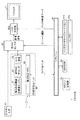
以下、本発明の一実施の形態によるワイヤレスAVシステムについて図面を参照しつつ説明を行う。図1は、本実施の形態によるワイヤレスAVシステムの構成例を示す図である。図2は、本実施の形態によるワイヤレスAVシステムにおけるワイヤレスセンタ(チューナ側装置)の構成例を示す機能ブロック図である。図3は、本実施の形態によるワイヤレスAVシステムにおけるTV本体(モニタ側装置)の構成例を示す機能ブロック図である。図4は、本実施の形態によるワイヤレスAVシステムにおいてワイヤレスセンタとTV本体との間で送受信されるデータの構造の一例を示す図である。図5は、リモートコントロール装置の構成例である。図6及び図7は、本発明の実施の形態によるワイヤレスAVシステムにおけるGUI映像の表示例を示す図である。図8は、本実施の形態によるワイヤレスAVシステムにおける処理例の流れを示すフローチャートである。 Hereinafter, a wireless AV system according to an embodiment of the present invention will be described with reference to the drawings. FIG. 1 is a diagram showing a configuration example of a wireless AV system according to the present embodiment. FIG. 2 is a functional block diagram showing a configuration example of a wireless center (tuner-side device) in the wireless AV system according to the present embodiment. FIG. 3 is a functional block diagram showing a configuration example of the TV main body (monitor-side device) in the wireless AV system according to the present embodiment. FIG. 4 is a diagram showing an example of the structure of data transmitted and received between the wireless center and the TV main body in the wireless AV system according to the present embodiment. FIG. 5 is a configuration example of a remote control device. FIGS. 6 and 7 are diagrams showing examples of displaying GUI images in the wireless AV system according to the embodiment of the present invention. FIG. 8 is a flowchart showing a flow of a processing example in the wireless AV system according to the present embodiment.
図1に示すように、本実施の形態によるワイヤレスAVシステム1は、チューナ側のワイヤレスセンタ3と、バッテリー内蔵の液晶モニタ付きのTV本体(テレビ本体)5とを含んで構成されている。
As shown in FIG. 1, the
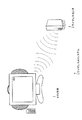
また、図9に示すように、TV本体5は、バッテリー内蔵でワイヤレスである。また、リモートコントローラを備えて、ビデオデッキなどのリモコン操作ができるようになっている。また、ワイヤレスセンタ3は、BSやU/V等のアンテナやDVDプレーヤやビデオデッキ等のAV機器、CATV用セットトップボックス等に接続されている。そして、ワイヤレスセンタ3からTV本体5へ、テレビ番組等の映像及び/又は音声データがワイヤレス伝送されるようになっている。
As shown in FIG. 9, the TV
つぎに、ワイヤレスAVシステム1の構成について具体的に説明する。図1に示すように、ワイヤレスセンタ3は、外部入力切換のための端子である、ビデオ1入力(S端子付き)端子7aと、ビデオ2入力(デコーダ入力)端子7bと、ビデオ3入力(モニタ/BS出力兼用)端子7cと、AC電源端子11a及びCar−DC端子11bと、BSアンテナ15a、UHF/VHFアンテナ15bと、ダイバーシティーアンテナ15cとを有している。一方、TV本体5は、ビデオ4入力(TV出力)端子21と、AC電源端子23a及びCar−DC端子23bと、を有している。
Next, the configuration of the
ワイヤレスセンタ3とTV本体5とは、例えばIEEE802.11b規格に基づく無線方式により、互いにデータの送受信を行うことが可能である。ワイヤレスセンタ3からTV本体5に向けて、無線によりMPEG2ストリーム情報が送られるとともに、その他のコマンドデータなどが両者間で双方向通信により伝送される。
The
つぎに、ワイヤレスセンタ3の構成例について図2を参照して説明する。図1において説明した構成要素については説明を省略する。図2に示すように、ワイヤレスセンタ3は、ワイヤレスセンタ3全体を制御するワイヤレスセンタマイコン41と、第1AVセレクタ43と、SS(Spread Spectrum:スペクトラム拡散)送受信ユニット45と、を有している。ビデオ1入力端子(外部入力1)7a,ビデオ2入力端子(外部入力2)7b,ビデオ3入力端子(外部入力3)7cは、例えばビデオデッキやDVDレコーダ等の外部装置からの映像信号および/または音声信号を第1AVセレクタへ入力するための端子である。
Next, a configuration example of the
さらに、ワイヤレスセンタ3は、BS(broadcasting satellite)放送を受信するBSアンテナ15aに接続されるBSチューナ33と、テレビ放送(アナログ放送またはデジタル放送)を受信するUHF/VHFアンテナ15bに接続されるU/Vチューナ31と、を有している。また、ワイヤレスセンタ3においては、ワイヤレスセンタマイコン41が出力する選局コマンド31aに基づいてテレビ番組の選局処理が行われる。選局処理が行われた後、U/Vチューナ31またはBSチューナ33から出力される信号は、映像・音声復調器35に入力し、映像信号(第一の映像のデータ)および音声信号に復調される。また、復調された音声信号は、音声切換部37において、ワイヤレスセンタマイコン41が出力する音声切換コマンド37aに基づいて音声切換処理が行われる。さらに、復調された映像信号と音声切換処理が行われた後の音声信号とは、第1AVセレクタ43に入力される。ここで、第1AVセレクタ43は、ワイヤレスセンタマイコン41からのソース選択信号43aに基づいてソース選択処理を行い、選択した映像信号および音声信号をSS送受信ユニット45に入力する。
Further, the
また、ワイヤレスセンタマイコン41は、EEPROM(第1記憶手段)47に格納されている各種データを読み出すと共に、EEPROM47へ各種データを書き込むことが可能である。なお、EEPROM47は、ワイヤレスセンタマイコン41の制御プログラム、通信制御データ、さらに伝送チャネル変更プログラム等の種々のデータを記憶する電気的に書換可能な不揮発性メモリである。
Further, the
SS送受信ユニット45は、A/D変換器51と、MPEG2エンコーダ53と、第1のSS無線送受信エンジン55と、これらを制御する第1のSS―CPU(送信手段)57とを有している。第1AVセレクタ43から出力された映像信号および音声信号は、A/D変換器51によりA/D変換され、例えばMPEG2エンコーダ53によりMPEG2形式にエンコードされ、ワイヤレスセンタマイコン41からのTVコマンド(送受信コマンド)57aに基づいてMPEG2形式にエンコードされる。そして、このエンコードされたデータは、第1のSS―CPU57の制御の下、第1のSS無線送受信エンジン55によって、TV本体5側に送られる。また、第1のSS無線送受信エンジン55は、第1のSS―CPU57に制御されることにより、種々のコマンド(データ)をTV本体5との間で双方向に通信する。
The SS transmission / reception unit 45 has an A / D converter 51, an
つぎに、TV本体5の構成について図3に基づいて説明する。同図に示すように、TV本体5は、TVマイコン66と、SS送受信ユニット61と、第2AVセレクタ67と、TVモニタ(液晶ディスプレイ,表示部)71と、リモートコントロール装置(図5)の入力を受け付けるリモコン受光部75と、を有している。SS送受信ユニット61は、第2のSS無線送受信エンジン77と、MPEG2デコーダ81と、D/A変換器83と、これらを制御する第2のSS―CPU85とを有している。さらに、TV本体5は、バッテリー駆動に対応しており、それに応じてバッテリー87bとバッテリーチャージャーマイコン87aとを有している。
Next, the configuration of the TV
ここで、TVマイコン66は、EEPROM(第2記憶手段、記憶部)65に格納されている各種データを読み出すと共に、EEPROM65へ各種データを書き込むことが可能である。なお、EEPROM65は、TV本体5の制御プログラム、通信制御データ、さらに伝送チャネル変更プログラム等の種々のデータを記憶する電気的に書換可能な不揮発性メモリである。
Here, the
ワイヤレスセンタ3側から送られMPEG2形式にエンコードされているストリーミング情報(上記のエンコードされたデータ)は、TVマイコン66からのTVコマンド(送受信コマンド)71を受けた第2のSS―CPU(受信手段)85の指示により、SS送受信ユニット61内の第2のSS無線送受信エンジン77において受信され、MPEG2デコーダ81においてデコードされ、D/A変換器83においてD/A変換される。さらに、D/A変換されることにより生成した映像信号および音声信号は、第2AVセレクタ67に送られる。そして、第2AVセレクタ67は、この映像信号および音声信号と、ビデオ4入力端子(外部入力4)21からの映像信号および音声信号(例えば、ビデオデッキ等の外部装置からの映像信号等)とのいずれを選択するかをTVマイコン66からのソース選択コマンド67aに基づいて選択する。ここで、選択された映像信号(第一の映像のデータ)および音声信号は、OSD合成部93aを介してTVモニタ71に送られる。これにより、第2AVセレクタ(第一映像生成手段)67により選択された映像信号に基づく映像がTVモニタ71に表示される。なお、以下では、ワイヤレスセンタ3によって受信されたテレビ放送の映像がTVモニタ71に表示されているものとするが、ここで、テレビ放送の映像とは、地上波アナログ放送、地上波デジタル放送のテレビ映像のみならず、衛星放送の映像、データ放送の映像、CATV放送の映像等も含まれる。また、TVモニタ71に表示される映像(第一の映像)は、テレビ放送用の映像に限られるものではなく、ビデオデッキやDVDレコーダからの再生映像であってもよい。
The streaming information (encoded data described above) sent from the
また、本実施の形態におけるTV本体5は、OSD機能を有している。以下では、OSD機能を実現するための構成について説明する。なお、本実施の形態におけるOSD機能とは、TVモニタ71に表示されている映像上の一部領域に、この映像とは異なる映像(以下、OSD映像という)を重畳して表示する機能をいう。
Further, the TV
また、本実施の形態におけるOSD映像(第二の映像)とは、ワイヤレスセンタ3,TVモニタ71に関連する情報に基づいて生成される映像であり、例えば、ワイヤレスセンタ3またはTVモニタ71の設定状態(選局されているチャンネル番号,出力音量,映像の明るさ等)を示す映像、受信可能なチャンネル番号を示す映像、ワイヤレスセンタ3またはTVモニタ71を操作するためのGUI映像、ワイヤレスセンタ3が受信するテレビ放送用の映像信号以外のデータに基づく映像(例えば、EPG)がある。
The OSD video (second video) in the present embodiment is a video generated based on information related to the
なお、利用者は、TVモニタ71にGUI映像をOSD表示させる場合、このGUI映像を介して、選局チャンネルの切り替え、音量調整、表示される映像の輝度調整、タイマー設定等の各種操作を行うことができる。また、利用者は、上記GUI映像に表示されている各種制御コマンドの選択、決定、取り消し等をリモートコントロール装置200(図5参照)を操作して行ってもよく、また、TV本体5に取り付けられているコントローラ(不図示)を操作して行ってもよい。
When the GUI image is displayed on the
本実施の形態においては、利用者がリモートコントロール装置200を操作することによってOSD表示の指示をTV本体5に入力すると、TVマイコン(第二映像生成手段)66が、EEPROM65に格納されている各種データに基づいて、この指示に応じたOSD映像データ(第二の映像のデータ)を生成し、OSD合成部93aへ出力する(図10参照)。そして、OSD合成部(映像重畳手段)93aが、TVモニタ71に表示されているテレビ放送の映像に対してOSD映像を重畳する処理を行う。以下、このOSD合成部93aについて詳細に説明する。
In the present embodiment, when the user inputs an OSD display instruction to the TV
OSD合成部93aは、図10に示すように、同期信号分離部193およびスイッチ194を備えている。スイッチ194は、TVマイコン66から入力するタイミング制御信号に基づいて、同期信号分離部193とTVモニタ71との接続/切断、TVマイコン66とTVモニタ71との接続/切断を切り替えるスイッチである。同期信号分離部193は、第2AVセレクタ67より送られる映像信号から映像同期信号を分離して、上記映像信号をスイッチ194へ出力すると共に、上記映像同期信号をTVマイコン66へ出力するブロックである。
As shown in FIG. 10, the
以上の構成において、まず、同期信号分離部193は、入力する映像信号から映像同期信号を分離し、上記映像信号をスイッチ194へ送信すると共に、上記映像同期信号をTVマイコン66へ送信する。
In the above configuration, first, the synchronization
ここで、TVマイコン66は、利用者からのOSD表示の指示を入力した場合、この指示に応じたOSD映像データを生成し、OSD合成部93aへ出力する。さらに、TVマイコン66は、同期信号分離部193からの映像同期信号に基づき、スイッチ194を切り替えるタイミングを示したタイミング制御信号を生成し、このタイミング制御信号をスイッチ194へ送信する。
Here, when an instruction for OSD display is input from the user, the
そして、スイッチ194は、このタイミング制御信号に基づき、同期信号分離部193とTVモニタ71との接続/切断、TVマイコン66とTVモニタ71との接続/切断を切り替える。これにより、利用者からのOSD表示の指示がTV本体5に入力されると、TVマイコン66からTVモニタ71へOSD映像データが送られ、TVモニタ71上に表示されているテレビ放送の映像上にOSD映像が重畳される。
The
つまり、TVマイコン66から出力されるOSD映像データは、第2AVセレクタ67とTVモニタ71との間に位置するOSD合成部93aに入力される。TVマイコン66は、例えば、後述するリモートコントロール装置(図5参照)の入力キーなどを用いて入力されたコマンドをリモコン受光部75において受け取り、この受け取ったコマンドに基づいて、TVモニタ71にOSD表示を行う。
That is, the OSD video data output from the
つぎに、ワイヤレスセンタ3とTV本体5との間で送受信されるデータについて詳細に説明する。図4に示すように、本実施の形態によるワイヤレスAVシステム1において、ワイヤレスセンタ3側とTV本体5側との間でやり取りされる送受信データ131は、第1のSS無線送受信エンジン55と第2のSS無線送受信エンジン77との間で、アイソサイクル(isocycle)132によって規定された一定周期毎に送受信処理を行う。送受信データパケットの構成は、ルート(R)であるワイヤレスセンタ3からリーフ(L)であるTV本体5に送られるRパケット133と、ギャップ134と、ギャップ134を挟んでリーフ(L)であるTV本体5からルート(R)であるワイヤレスセンタ3に送られるLパケット135とを有して構成されている。
Next, data transmitted and received between the
Rパケット133は、ロングプリアンブル(1Mbps)を使用する部分と、その他のデータ部分(11MHz)と、を含んでいる。ロングプリアンブル(1Mbps)を使用する部分は、シンクロナスデータ141とPHYヘッダデータ143を含んでおり、192μsの期間である。一方、その他のデータ部分は、MACヘッダ145と、コントロールデータ(CB)147と、非同期データにより構成されるステイタスコマンドデータ151と、同期データ(アイソクロナスデータ)153とを有している。ステイタスコマンドデータ151は、ワイヤレスセンタ3からTV本体5側へ送られるステータス・コマンドを含むデータである。同期データ153はMPEG2のAVストリームデータである。
The
上記Rパケット133に続き、129μsのギャップ部(GAP)134が設けられ、次いで、TV本体5側からワイヤレスセンタ3に送られるLパケット135が設けられている。Lパケット135は、Rパケット133と同様に、ロングプリアンブル(1Mbps)を使用する部分161、163と、その他のデータ部分(11MHz)である、MACヘッダ部165、リトライタグ167と、非同期データ部171と、を含んでいる。非同期データ部171は、TV本体5側からワイヤレスセンタ3側へ送られるステータス・コマンドを含むデータである。後述するように、TVモニタ71に表示されたGUI上で選択され確定されたコマンドデータは、非同期データ部171に含めてTV本体5側からワイヤレスセンタ3側に送られる。ワイヤレスセンタ3側においては、上記コマンドデータに基づいて指示されたコマンドを実行する。以上説明したデータが、全体として3.6msサイクルで送られる。
Following the
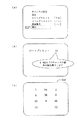
図5は、TV本体5側のリモコン受光部75を介して種々の操作を行う入力部としての機能を有するリモートコントロール装置200の構成例である。図5に示すように、リモートコントロール装置200は、チャンネル番号を入力するチャンネル番号入力部201と、メニュー表示ボタン202と、選択・決定ボタン203a・203bと、アップダウン選局ボタン205と、電源スイッチ207と、(外部)入力切換ボタン208と、を有している。図6および図7は、TVモニタ71上に表示されるOSD映像の例を示す図であり、リモートコントロール装置200における入力に基づいてTVマイコン66がTVモニタ71に表示させたOSD映像の例である。
FIG. 5 is a configuration example of a
まず、図8に示すように、リモートコントロール装置200を用いてメニューボタン202を押すと(S1)、TVモニタ71には、例えば、図6(a)に示すような表示が行われる(S2)。このメニュー表示では、例として、映像調整と、省エネ設定と、本体設定と、チャンネル設定とタイマー設定とが表示されている。ここで、チャンネル設定を選択すると(S3)、図6(b)に示す表示が行われる(S4)。図6(b)に示すように、チャンネル設定に関するメニュー表示には、例えば、オートプリセットと、マニュアルメモリーと、地域番号と、実行と、が表示されている。ここではオートプリセットを選択すると(S5)、図6(c)に示すようなメニュー表示となり、ここで決定ボタン203bを押すことによりオートプリセット処理を行う旨が決定され、上下選択ボタン203aにより図7(a)に示すように実行を選択し決定ボタン203bを押すことによりオートプリセット処理の実行が確定する(S7)。上記の処理は、TV本体5側において行われる。以上の手順によりワイヤレスセンタ3側に実行させるための処理(オートプリセット処理)が確定したため、これをワイヤレスセンタ3側に対するコマンドに変換し(S7)、図4に示す非同期データ部171に含めてTV本体5側からワイヤレスセンタ3側に送る(S8)。
First, as shown in FIG. 8, when the
ワイヤレスセンタ3側において上記オートプリセットを実行する旨のコマンドを受け取ると、図7(b)に示すように、チャンネル関係の表示画面においてオートプリセット中である旨の表示がされ、オートプリセット処理が完了すると(S9)、関連する情報(チャンネル特定情報)がTV本体5側に送られ(S10)、図7(c)に示すように、ダイレクト選局ボタンに対応した選局番号の順に左上から記憶されたチャンネル番号の一覧213がTVモニタ71に表示される。図7(c)に示す例では、1,3,4,6,8,10,12のチャンネル番号は、各々同一の選局番号に対応して記憶され、13から62チャンネルのうちの38,42,46は、空きの選局番号に記憶される。リモコンにおける1チャンネルの位置には1チャンネルが、2チャンネルの位置には14チャンネルが、3チャンネルの位置には3チャンネルが、4チャンネルの位置には4チャンネルが、5チャンネルの位置には38チャンネルがというように、対応付けされている。例えばこれらの対応付けされた情報は、チャンネル特定情報として、TV本体5側に送られ、図3に示すEEPROM65に記憶される。
When the
本実施の形態によるワイヤレスAVシステム1においては、TV本体5側に設けられたTVマイコン66において、TVモニタ71に表示されるOSD映像を生成し、処理に関する選択などを全てTV本体5側において行うことができるため、従来のようにOSD映像を含むビデオ信号をAVストリームへ変換するために表示レスポンスが劣化するという問題を解消できる。
In the
以上、本発明に関して実施の形態に沿って説明を行ったが、本発明はこれらの例に限定されるものではなく、種々の変形が可能であるのは言うまでもない。また、テレビ放送の受信を行うシステムを例にして説明したが、他のAVシステムにも適用可能である。また、ワイヤレスであるAV機器に対して適用した例に基づいて説明したが有線などによりネットワーク化されたAV機器にも適用できるのは言うまでもない。また、切換処理に関して映像のミュート処理を行うことを例にして説明したが、他の映像処理を行っても良い。 As described above, the present invention has been described in accordance with the embodiments. However, it is needless to say that the present invention is not limited to these examples, and various modifications are possible. In addition, although a system for receiving a television broadcast has been described as an example, the present invention can be applied to other AV systems. In addition, the description has been given based on the example in which the present invention is applied to wireless AV devices. However, it is needless to say that the present invention can also be applied to AV devices networked by wire or the like. In addition, although an example has been described in which the video mute process is performed for the switching process, other video processes may be performed.
〔実施の形態2〕
本実施の形態では、実施の形態1にて説明したオートプリセット処理とは異なる態様のオートプリセット処理について説明する。なお、以下では、説明の便宜上、実施の形態1で説明した部材と実質的に同一の機能を奏する部材については、同一の符号を付し、その説明を省略する。また、実施の形態1で述べた各種の特徴点については、本実施の形態についても組み合わせて適用し得るものとする。
[Embodiment 2]
In the present embodiment, an auto preset process different from the auto preset process described in the first embodiment will be described. In the following, for convenience of description, members having substantially the same functions as those described in
図11は、本実施の形態に係るオートプリセット処理のうち、TV本体5側で実行される処理の手順を示したフローチャートである。
FIG. 11 is a flowchart showing a procedure of a process executed on the TV
まず、TVモニタ71上に表示されているテレビ番組の映像上に、図6(a)に示すメニュー選択用映像がOSD表示されているものとする。図10に示すS11において、利用者がリモートコントロール装置200を操作して、チャンネル設定メニューを選択すると(S11)、TVマイコン66は、チャンネル設定用映像のデータをEEPROM65から読み出し、OSD合成部93aへ出力する(S12)。これにより、TVモニタ71において、図6(b)に示されるチャンネル設定用映像がOSD表示される(S13)。
First, it is assumed that an image for menu selection shown in FIG. 6A is OSD-displayed on an image of a television program displayed on the
ここで、利用者が、チャンネル設定用映像に表示されている各項目のうち、オートプリセット処理を選択すると(S14においてYes)、TVマイコン66は、オートプリセット処理の実行を示すコマンドを出力する(S15)。なお、その他の処理が選択された場合(S14においてNo)、その他の処理が実行される(S16)。
Here, when the user selects the auto-preset process from the items displayed in the channel setting video (Yes in S14), the
そして、S15においてTVマイコン66が出力したコマンドは、SS送受信ユニット61に送られる(S17)。さらに、このコマンドを受け取ったSS送受信ユニット61は、第2のSS−CPU85の制御の下、第2のSS無線送受信エンジン77を介して、ワイヤレスセンタ3にこのコマンドを送信する(S18)。これにより、ワイヤレスセンタ3側に処理が移行される(S19)。
Then, the command output by the
つぎに、上記のコマンドを受け取ったワイヤレスセンタ3において実行される処理を図12に基づいて説明する。図12は、図11におけるS19の処理の詳細を示したものであり、ワイヤレスセンタ3側で実行される処理の手順を示したフローチャートである。
Next, processing executed in the
S18に示すコマンド(図11参照)がTV本体5から送信されると、ワイヤレスセンタ3のSS送受信ユニット45はこのコマンドを受信する(S31)。そして、受信されたコマンドは、第1のSS−CPU57の制御の下、ワイヤレスセンタマイコン41に入力される(S32)。
When the command shown in S18 (see FIG. 11) is transmitted from the TV
さらに、このコマンドを受け取ったワイヤレスセンタマイコン41は、コマンドの示す内容を解析する(S33)。ここで、コマンドの内容がオートプリセット操作を指示するものである場合(S34においてYes)、BSチューナ33およびU/Vチューナ31に対してチャンネルサーチの制御信号を出力する(S35)。なお、S33において、コマンドの内容がその他の指示である場合(S34においてNo)、その他の処理が実行される(S36)。
Further, the
そして、チャンネルサーチの制御信号を受け取った両チューナ31、33は、チャンネルサーチを行い、受信可能なチャンネルと受信不可能なチャンネルとを示すチャンネル特定情報をワイヤレスセンタマイコン41へ出力する(S37)。
The
さらに、このチャンネル特定情報を受け取ったワイヤレスセンタマイコン41は、SS送受信ユニット45にチャンネル特定情報を送信する。そして、SS送受信ユニット45は、第1のSS−CPU57の制御の下、第1のSS無線送受信エンジン55を介して、TV本体5にチャンネル特定情報を送信する(S38)。
Further, the
つぎに、ワイヤレスセンタ3から上記のチャンネル特定情報が送信された後のTV本体5側の処理について図11に基づいて説明する。
Next, processing on the TV
ワイヤレスセンタ3から上記のチャンネル特定情報が送信されると、このチャンネル特定情報は、第2のSS−CPU85の制御の下、第2のSS無線送受信エンジン77に受信される(S20)。そして、この受信されたチャンネル特定情報は、TVマイコン66の制御の下、EEPROM65に記憶される(S21)。
When the channel identification information is transmitted from the
以上のように、本実施の形態のワイヤレスAVシステム1では、受信可能なチャンネルと受信不可能なチャンネルを示すチャンネル特定情報(関連データ)を、TV本体5におけるEEPROM65に記憶させている。したがって、TVモニタ71に表示されているテレビ番組の映像上に、図7(c)に示すような受信可能なチャンネルを示すOSD映像を重畳して表示する場合、TVマイコン66が、EEPROM65に記憶されているチャンネル特定情報に基づいてOSD映像のデータを生成し、OSD合成部93aが、TVモニタ71に表示されているテレビ番組の映像上にこのOSD映像を重畳して表示することになる。
As described above, in the
つまり、本実施の形態によれば、ワイヤレスセンタ3からのデータに基づくOSD映像を表示する場合、このOSD映像をワイヤレスセンタ3側で生成せず、TV本体5側で生成している。したがって、このOSD映像をワイヤレスセンタ3側で生成する従来の構成と比べ、テレビ番組の映像にOSD映像を重畳したデータをエンコード・デコードする必要がなく、OSD表示に関し、利用者の指示の入力に対する応答速度を向上させることが可能となる。
That is, according to the present embodiment, when displaying the OSD video based on the data from the
特に、本実施の形態のように、EEPROM65に記憶されているデータに基づいてOSD映像のデータを生成する場合、利用者からOSD映像表示の指示を入力すると、直ぐにOSD表示を行うことが可能となる。
In particular, when generating OSD video data based on data stored in the
〔実施の形態3〕
本実施の形態では、GUIとしてのEPG映像(OSD映像)をTVモニタ71にOSD表示する処理について説明する。
[Embodiment 3]
In the present embodiment, a process of displaying an EPG video (OSD video) as a GUI on the
なお、以下では、説明の便宜上、実施の形態1で説明した部材と実質的に同一の機能を奏する部材については、同一の符号を付し、その説明を省略する。また、実施の形態1で述べた各種の特徴点については、本実施の形態についても組み合わせて適用し得るものとする。
In the following, for convenience of explanation, members having substantially the same functions as those described in
また、本実施の形態のワイヤレスAVシステム1では、U/Vチューナ31からデジタル放送用地上波を受信し、このデジタル放送用地上波にはEPGデータが付加されているものとする。さらに、ワイヤレスセンタ3は、このEPGデータを受信すると、このEPGデータをTV本体5へ送信し、TV本体5において、TVマイコン66が、ワイヤレスセンタ3から送られてきたEPGデータ(関連データ)をEEPROM65に格納できる構成であるものとする。
Further, in the
なお、ワイヤレスセンタ3がBSチューナ33から衛星デジタル放送波を受信する構成である場合、ワイヤレスセンタ3はその放送波に付加されているEPGデータをTV本体5へ送信するようにしてもよい。
When the
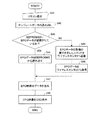
図13は、EPG映像をOSD表示する手順について示したフローチャートである。まず、利用者が、リモートコントロール装置200を操作して、EPGの表示指示を入力すると(S41)、TVマイコン66が、EPG映像のテンプレートデータをEEPROM65から読み出す(S42)。なお、このテンプレートデータとは、EPG映像をGUIとして機能させるために必要な定型データである。
FIG. 13 is a flowchart showing a procedure for displaying an EPG image by OSD. First, when the user operates the
さらに、TVマイコン66は、EEPROM65にEPGデータが記憶されているか否かを判定する(S43)。ここで、このEPGデータがEEPROM65に既に記憶されている場合(S43においてYes)、TVマイコン66は、このEPGデータを読み出す(S44)。また、このEPGデータがEEPROM65に記憶されていない場合(S43においてNo)、TVマイコン66は、SS送受信ユニット61を介して、EPGデータの取得の実行を示したコマンドをワイヤレスセンタ3に送信する(S45)。これに応じて、ワイヤレスセンタ3側において、ワイヤレスセンタマイコン41は、U/Vチューナ31が受信しているデジタル地上波からEPGデータを取得し、このEPGデータをTV本体5へ送信する。これにより、TVマイコン66は、EPGデータをワイヤレスセンタ3から取得することができる(S46)。
Further, the
S44またはS46によってEPGデータを取得したTVマイコン66は、EPGデータに示される各番組のコンテンツ情報(番組名、出演者名等)を上記のテンプレートデータにあてはめることにより、EPG映像のデータを生成する(S47)。そして、このEPG映像のデータは、TVマイコン66からOSD合成部93aに送信される。これにより、TVモニタ71に表示されているテレビ映像上にEPG映像がOSD表示される(S48)。ここで、図14(a)の参照符300は、EPG映像の一例を示したものである。なお、同図におけるEPG映像300の各枠内には便宜上図形を示しているが、実際には番組のコンテンツ情報が表示されているものとする。
The
以上のように、本実施の形態のワイヤレスAVシステム1では、TV本体5側において、TVマイコン66が、EEPROM65からEPGデータを読み出すか、またはワイヤレスセンタ3からEPGデータを取得し、このEPGデータに基づいてEPG映像を生成する処理を行っている。さらに、OSD合成部93aが、TVモニタ71に表示されるテレビ放送の映像上に、このEPG映像を重畳する処理を行っている。
As described above, in the
つまり、本実施の形態によれば、このEPG映像を生成してテレビ放送の映像に重畳する処理をワイヤレスセンタ3側で行わず、TV本体5側で行っている。したがって、このEPG映像を生成してテレビ放送の映像に重畳する処理をワイヤレスセンタ3側で行う従来の構成と比べ、テレビ番組の映像にEPG映像を重畳した重畳映像のデータをエンコード・デコードする必要がなく、EPG映像をOSD表示する処理に関し、利用者の指示の入力に対する応答速度を向上させることが可能となる。
That is, according to the present embodiment, the process of generating the EPG video and superimposing it on the television broadcast video is not performed on the
また、TVマイコン66が、EEPROM65に格納されているEPGデータおよびテンプレートデータに基づいてEPG映像のデータを生成する場合(S44,S47)、EPG映像をOSD表示する時にTV本体5とワイヤレスセンタ3との間において通信状態が悪化すると、TVモニタ71に表示されるテレビ番組等の映像は劣化するが、OSD表示されるEPG映像が劣化することはない。これは、既にワイヤレスセンタ3から送信されると共にEEPROMに保存されたEPGデータに基づき、TV本体5においてEPG映像のデータを生成しているため、EPG映像の表示については通信状態の良否の影響を受けないからである。
When the
また、TVマイコン66が、EEPROM65に格納されているテンプレートデータと、EEPROM65を介さずにワイヤレスセンタ3から取得したEPGデータとに基づいてEPG映像のデータを生成する場合(S46,S47)、EPG映像をOSD表示する時にTV本体5とワイヤレスセンタ3との間において通信状態が悪化すると、OSD表示されるEPG映像のうち、番組のコンテンツ情報を示した箇所は一部劣化するが、このEPG映像の定型箇所は劣化しない。これは、通信状態が悪化しても、EPG映像の定型箇所はEEPROM65に保存されているテンプレートデータに基づいて生成されているため、この定型箇所の表示については通信状態の良否の影響を受けないからである。
When the
さらに、図を用いて具体的に説明する。EPG映像の生成処理、テレビ番組の映像にEPG映像を重畳する処理をワイヤレスセンタ3側にておこなっている従来の構成によれば、TV本体5とワイヤレスセンタ3との間において通信状態が悪化すると、図14(b)に示すように、TVモニタ71に表示される映像全体が劣化する。
This will be described more specifically with reference to the drawings. According to the conventional configuration in which the generation processing of the EPG video and the processing of superimposing the EPG video on the video of the television program are performed on the
これに対し、EEPROM65に格納されているテンプレートデータと、EEPROM65を介さずにワイヤレスセンタ3から取得したEPGデータとに基づき、TV本体5側にてEPG映像のデータを生成する場合、TV本体5とワイヤレスセンタ3との間において通信状態が悪化すると、図14(c)に示すように、TVモニタ71に表示されるテレビ番組等の映像は劣化するものの、EPG映像の定型箇所は劣化していない。但し、EPGデータの取得について通信状態の良否の影響を受けるため、EPGデータに基づいて作成される番組のコンテンツ情報を示した箇所(図中の参照符b)については一部抜けが生じる。
On the other hand, when the
なお、以上の各実施の形態では、TVモニタ71に表示されるテレビ番組の映像を生成する第2AVセレクタ67、TVモニタ71に表示されるテレビ番組の映像上にOSD画像を重畳するOSD合成部93aがハードウェアで実現されている場合を例にして説明したが、これに限るものではない。第2AVセレクタ67、OSD合成部93aは、上述した機能を実現するためのプログラムと、そのプログラムを実行するハードウェア(コンピュータ)との組み合わせで実現してもよい。
In each of the above-described embodiments, the
また、本実施の形態のワイヤレスAVシステムは、放送情報に基づく表示を行う表示部と、該表示部にGUIを表示させ、表示されたGUIに基づいて選択される制御項目に対応する制御データを生成するGUI制御部と、該制御データを送るとともに前記放送情報を受ける第1の送受信部と、を有するAV出力装置と、前記放送情報に関するチャンネル選択を行うチューナ部と、前記第1の送信部とワイヤレスにより関連付けされ前記チューナ部により選局された放送情報を前記第1の送受信部に送るとともに前記制御データを前記第1の送受信部から受け取る第2の送受信部と、を有するワイヤレスセンタと、を具備する構成としてもよい。 Further, the wireless AV system according to the present embodiment has a display unit for performing display based on broadcast information, a GUI displayed on the display unit, and control data corresponding to a control item selected based on the displayed GUI. An AV output device having a GUI control unit for generating, a first transmitting / receiving unit for transmitting the control data and receiving the broadcast information, a tuner unit for selecting a channel related to the broadcast information, and the first transmitting unit A second transmission / reception unit that transmits broadcast information selected by the tuner unit wirelessly associated with the first transmission / reception unit and receives the control data from the first transmission / reception unit; May be provided.
さらに、本実施の形態のワイヤレスAVシステムは、上記構成に加えて、放送情報に基づく表示を行う表示部と、該表示部にGUIを表示させるためのOSD出力を生成するとともに、表示された前記GUIに基づいて選択される制御項目に対応する制御データを生成するGUI制御部と、該制御データを送るとともに前記放送情報を受ける第1の送受信部と、を有するAV出力装置と、前記放送情報に関するチャンネル選択を行うチューナ部と、前記第1の送信部とワイヤレスにより関連付けされ前記チューナ部により選局された放送情報を前記第1の送受信部に送るとともに前記制御データを前記第1の送受信部から受け取る第2の送受信部と、を有するワイヤレスセンタと、を具備する構成とすることもできる。 Further, in addition to the above configuration, the wireless AV system according to the present embodiment generates a display unit that performs display based on broadcast information, and generates an OSD output for displaying a GUI on the display unit. An AV output device comprising: a GUI control unit that generates control data corresponding to a control item selected based on a GUI; a first transmission / reception unit that sends the control data and receives the broadcast information; A tuner unit for selecting a channel related to the first transmitter / receiver, transmitting broadcast information tuned by the tuner unit wirelessly associated with the first transmitter to the first transmitter / receiver and transmitting the control data to the first transmitter / receiver And a second transmission / reception unit that receives the information from the wireless center.
また、本実施の形態のワイヤレスAVシステムは、上記構成に加えて、さらに、前記AV出力装置が、前記GUIに関する操作コマンドをデコードするデコーダを有する構成とすることもできる。 Further, in addition to the above configuration, the wireless AV system according to the present embodiment may be configured such that the AV output device further includes a decoder for decoding an operation command related to the GUI.
さらに、本実施の形態のワイヤレスAVシステムは、上記構成に加えて、前記AV出力装置は、前記表示部に表示されたGUIに基づいて前記制御データを確定する制御データ入力確定手段と関連付けすることもできる。 Further, in the wireless AV system according to the present embodiment, in addition to the above configuration, the AV output device may be associated with control data input determination means for determining the control data based on a GUI displayed on the display unit. You can also.
また、本実施の形態のAV出力装置は、放送情報に関するチャンネル選択を行うチューナ部と、該チューナ部により選局された放送情報を送る第2の送受信部と、を有するワイヤレスセンタと関連付けされるAV出力装置であって、前記放送情報に基づく表示を行う表示部と、該表示部にGUIを表示させ、表示されたGUIに基づいて選択される制御項目に対応する制御データを生成するGUI制御部と、該制御データを前記ワイヤレスセンタに送るとともに前記放送情報を受ける第1の送受信部と、を有する構成とすることもできる。 Further, the AV output device according to the present embodiment is associated with a wireless center having a tuner unit for selecting a channel related to broadcast information and a second transmitting / receiving unit for transmitting broadcast information selected by the tuner unit. An AV output device, a display unit for displaying based on the broadcast information, and a GUI control for displaying a GUI on the display unit and generating control data corresponding to a control item selected based on the displayed GUI. And a first transmission / reception unit that sends the control data to the wireless center and receives the broadcast information.
さらに、本実施の形態のAV出力装置は、上記構成に加えて、放送情報に関するチャンネル選択を行うチューナ部を有するワイヤレスセンタと無線により関連付けされるAV出力装置であって、表示部と、該表示部上にGUIを提供するためのOSDを生成するOSD生成部とを有する構成としてもよい。 Further, in addition to the above configuration, the AV output device according to the present embodiment is an AV output device wirelessly associated with a wireless center having a tuner unit for selecting a channel for broadcast information, the display unit comprising: a display unit; An OSD generation unit that generates an OSD for providing a GUI on the unit may be provided.
また、本実施の形態のAV出力装置は、上記構成に加えて、前記OSD生成部は、前記ワイヤレスセンタからのエンコードされたストリーム映像をデコードした後のデータに対してOSDデータを付加する構成としてもよい。 In the AV output device of the present embodiment, in addition to the above-described configuration, the OSD generation unit may add OSD data to data obtained by decoding an encoded stream video from the wireless center. Is also good.
さらに、本実施の形態のワイヤレスセンタは、放送情報に基づく表示を行う表示部と、該表示部にGUIを表示させ、表示されたGUIに基づいて選択される制御項目に対応する制御データを生成するGUI制御部と、該制御データを送るとともに前記放送情報を受ける第1の送受信部と、を有するAV出力装置と関連付けされ、前記放送情報に関するチャンネル選択を行うチューナ部と、該チューナ部により選局された放送情報を前記AV出力装置に送るとともに前記制御データを受け取る第2の送受信部と、を有する構成としてもよい。 Further, the wireless center according to the present embodiment generates a display unit that performs display based on broadcast information, displays a GUI on the display unit, and generates control data corresponding to a control item selected based on the displayed GUI. A tuner section that is associated with an AV output device that has a GUI control section that performs control and a first transmission / reception section that sends the control data and receives the broadcast information, and a tuner section that selects a channel related to the broadcast information. A second transmission / reception unit that sends the broadcast information to the AV output device and receives the control data.
また、本実施の形態のGUI提供方法は、放送情報に関するチャンネル選択を行うチューナ部を有するワイヤレスセンタとワイヤレスによって関連付けされ、表示部を有するAV出力装置におけるGUI提供方法であって、GUIを操作するための入力に応じてその入力内容をデコードする第1のステップと、デコードされた前記入力内容に関するOSDを生成する第2のステップと、生成されたOSDにより前記表示部にGUIを表示させる第3のステップとを有することとしてもよい。 Further, the GUI providing method according to the present embodiment is a GUI providing method for an AV output device having a display unit, which is wirelessly associated with a wireless center having a tuner unit for selecting a channel for broadcast information, and operates the GUI. A first step of decoding the input content in response to an input for the second step, a second step of generating an OSD relating to the decoded input content, and a third step of displaying a GUI on the display unit using the generated OSD. May be included.
さらに、本実施の形態のGUI提供方法は、上記各ステップに加えて、表示されたGUIに基づき制御データを選択し確定するステップと、前記放送情報を受信するとともに確定された前記制御データを前記ワイヤレスセンタに送るステップとを有してもよい。 Further, in addition to the above steps, the GUI providing method according to the present embodiment further includes a step of selecting and confirming control data based on the displayed GUI, and receiving the broadcast information, and Sending to a wireless center.
以上示したワイヤレスAVシステムによれば、AV出力装置側において表示部に表示されるGUIを生成し、GUIに関する操作をAV出力装置側において行うことができる。 According to the wireless AV system described above, a GUI to be displayed on the display unit can be generated on the AV output device side, and operations relating to the GUI can be performed on the AV output device side.
また、以上示したワイヤレスAVシステムによれば、AV出力側に設けられたOSD出力部において液晶モニタに表示されるGUIを生成し、処理に関する選択などを全てモニタ側において行うため、GUI映像を含むビデオ信号をAVストリームへ変換するために表示レスポンスが良くないという問題を解消できる。 Further, according to the wireless AV system described above, a GUI displayed on the liquid crystal monitor is generated in the OSD output unit provided on the AV output side, and all the processing related selections and the like are performed on the monitor side. The problem that the display response is not good because the video signal is converted into the AV stream can be solved.
また、以上示したワイヤレスAVシステムによれば、AV出力装置側において表示部に表示されるGUIを生成し、GUIに関する操作をAV出力装置側において行うことができる。 Further, according to the wireless AV system described above, it is possible to generate a GUI to be displayed on the display unit on the AV output device side and to perform an operation related to the GUI on the AV output device side.
本発明は上述した各実施形態に限定されるものではなく、請求項に示した範囲で種々の変更が可能であり、上述した実施形態において開示された各技術的手段を適宜組み合わせて得られる実施形態についても本発明の技術的範囲に含まれる。 The present invention is not limited to the embodiments described above, and various modifications are possible within the scope of the claims, and the present invention can be implemented by appropriately combining the technical means disclosed in the embodiments. The form is also included in the technical scope of the present invention.
本発明のワイヤレスシステムは、映像及び/又は音声データを無線伝送する、例えばディスプレイ分離型のワイヤレスTV受信機のような家庭内AVネットワークシステムに好適であるが、これに限定されず、携帯電話機/PHS(Personal Handy-Phone System,登録商標)や携帯情報端末(PDA(Personal Digital Assistants))、TV受信機能を内蔵したパソコンモニターなどの無線通信機器に広く適用可能である。 The wireless system of the present invention is suitable for, but not limited to, a home AV network system such as a display-separated type wireless TV receiver for wirelessly transmitting video and / or audio data. The present invention is widely applicable to wireless communication devices such as a PHS (Personal Handy-Phone System, registered trademark), a portable information terminal (PDA (Personal Digital Assistants)), and a personal computer monitor with a built-in TV reception function.
1 ワイヤレスAVシステム(ワイヤレスシステム)
3 ワイヤレスセンタ(ベース機器)
5 TV本体(無線端末)
7a ビデオ1入力端子
7b ビデオ2入力端子
7c ビデオ3入力端子
11a AC電源端子
11b Car−DC端子
15a BSアンテナ
15b UHF/VHFアンテナ
15c ダイバーシティーアンテナ
21 ビデオ4入力端子
23a AC電源端子
23b Car−DC端子
31 U/Vチューナ
33 BSチューナ
35 映像・音声復調器
37 音声切換部
41 ワイヤレスセンタマイコン
43 第1AVセレクタ
45 SS送受信ユニット
47 EEPROM
51 A/D変換器
53 エンコーダ
55 第1のSS無線送受信エンジン
57 第1のSS−CPU(送信手段)
61 SS送受信ユニット
65 EEPROM(記憶部)
66 TVマイコン(第二映像生成手段)
67 第2AVセレクタ(第一映像生成手段)
71 TVモニタ(表示部)
75 リモコン受光部
77 第2のSS無線送受信エンジン
81 デコーダ
83 D/A変換器
85 第2のSS−CPU(受信手段)
93a OSD合成部(映像重畳手段)
193 同期信号分離部
194 スイッチ
200 リモートコントロール装置
1 wireless AV system (wireless system)
3 wireless center (base equipment)
5 TV body (wireless terminal)
51 A /
61 SS transmission /
66 TV microcomputer (second video generation means)
67 Second AV selector (first video generation means)
71 TV monitor (display unit)
75 remote control
93a OSD synthesis unit (video superimposition means)
193 synchronization
Claims (9)
ベース機器から、第一の映像のデータと、ベース機器および/または無線端末に関連する関連データとを受信する受信手段と、
上記第一の映像のデータに基づいて第一の映像を生成する第一映像生成手段と、
上記関連データに基づいて第二の映像を生成する第二映像生成手段と、
上記第一の映像に対して第二の映像を重畳し、重畳した映像を表示部に表示する映像重畳手段と、
を含むことを特徴とする無線端末。 A wireless terminal that transmits and receives data to and from a base device,
Receiving means for receiving, from the base device, data of the first video and related data relating to the base device and / or the wireless terminal;
First video generation means for generating a first video based on the data of the first video,
A second video generating means for generating a second video based on the related data,
Video superimposing means for superimposing the second video on the first video, and displaying the superimposed video on a display unit,
A wireless terminal comprising:
上記第二映像生成手段は、上記記憶部に記憶されている関連データに基づいて、第二の映像を生成することを特徴とする請求項1に記載の無線端末。 Including a storage unit for storing the relevant data received by the receiving means,
2. The wireless terminal according to claim 1, wherein the second video generation unit generates a second video based on related data stored in the storage unit. 3.
請求項1ないし4のいずれか1項に記載の無線端末へ上記第一の映像のデータおよび上記関連データを送信する送信手段を含むベース機器と、
から構成されることを特徴とするワイヤレスシステム。 A wireless terminal according to any one of claims 1 to 4,
A base device including a transmission unit configured to transmit the first video data and the related data to the wireless terminal according to any one of claims 1 to 4,
A wireless system comprising:
ベース機器から、第一の映像のデータと、ベース機器および/または無線端末に関連する関連データとを受信するステップと、
上記第一の映像のデータに基づいて第一の映像を生成するステップと、
上記関連データに基づいて第二の映像を生成するステップと、
上記第一の映像に対して第二の映像を重畳し、重畳した映像を表示部に表示するステップと、
を含むことを特徴とする無線端末の制御方法。 A method for controlling a wireless terminal that transmits and receives data to and from a base device,
Receiving, from the base device, data of the first video and associated data associated with the base device and / or the wireless terminal;
Generating a first video based on the data of the first video,
Generating a second video based on the relevant data;
Superimposing a second video on the first video, and displaying the superimposed video on a display unit;
A method for controlling a wireless terminal, comprising:
Priority Applications (6)
| Application Number | Priority Date | Filing Date | Title |
|---|---|---|---|
| JP2004118359A JP2004336734A (en) | 2003-04-17 | 2004-04-13 | Wireless terminal, base apparatus, wireless system, control method of wireless terminal, control program of wireless terminal, and computer-readable recording medium for recording the same |
| EP04727755A EP1619887A4 (en) | 2003-04-17 | 2004-04-15 | Radio terminal, base device, wireless system, radio terminal control method, radio terminal control program, and computer-readable recording medium containing the control program |
| CN 200710167031 CN101202826B (en) | 2003-04-17 | 2004-04-15 | Radio AV system |
| KR1020057019584A KR100760773B1 (en) | 2003-04-17 | 2004-04-15 | Wireless av system, av output apparatus, wireless center, method of providing gui |
| PCT/JP2004/005423 WO2004093441A1 (en) | 2003-04-17 | 2004-04-15 | Radio terminal, base device, wireless system, radio terminal control method, radio terminal control program, and computer-readable recording medium containing the control program |
| US10/553,283 US20060271965A1 (en) | 2003-04-17 | 2004-04-15 | Radio terminal, base device, wireless system, radio terminal control method, radio terminal control program, and computer-readable recording medium containing the control program |
Applications Claiming Priority (2)
| Application Number | Priority Date | Filing Date | Title |
|---|---|---|---|
| JP2003113359 | 2003-04-17 | ||
| JP2004118359A JP2004336734A (en) | 2003-04-17 | 2004-04-13 | Wireless terminal, base apparatus, wireless system, control method of wireless terminal, control program of wireless terminal, and computer-readable recording medium for recording the same |
Related Child Applications (1)
| Application Number | Title | Priority Date | Filing Date |
|---|---|---|---|
| JP2004118360A Division JP2004343727A (en) | 2003-04-17 | 2004-04-13 | Wireless av system, av output apparatus, wireless center, and gui providing method |
Publications (1)
| Publication Number | Publication Date |
|---|---|
| JP2004336734A true JP2004336734A (en) | 2004-11-25 |
Family
ID=33302232
Family Applications (1)
| Application Number | Title | Priority Date | Filing Date |
|---|---|---|---|
| JP2004118359A Pending JP2004336734A (en) | 2003-04-17 | 2004-04-13 | Wireless terminal, base apparatus, wireless system, control method of wireless terminal, control program of wireless terminal, and computer-readable recording medium for recording the same |
Country Status (5)
| Country | Link |
|---|---|
| US (1) | US20060271965A1 (en) |
| EP (1) | EP1619887A4 (en) |
| JP (1) | JP2004336734A (en) |
| KR (1) | KR100760773B1 (en) |
| WO (1) | WO2004093441A1 (en) |
Cited By (7)
| Publication number | Priority date | Publication date | Assignee | Title |
|---|---|---|---|---|
| JP2007037122A (en) * | 2005-07-25 | 2007-02-08 | Samsung Electronics Co Ltd | Broadcast receiving/transmitting device, radio a/v system, and control method of radio a/v system |
| JP2009044252A (en) * | 2007-08-06 | 2009-02-26 | Toshiba Corp | Information processor and program start control method |
| US10153502B2 (en) | 2014-12-08 | 2018-12-11 | Lockheed Martin Energy, Llc | Electrochemical systems incorporating in situ spectroscopic determination of state of charge and methods directed to the same |
| US10186726B2 (en) | 2013-10-16 | 2019-01-22 | Lockheed Martin Energy, Llc | Method and apparatus for measuring transient state-of-charge using inlet/outlet potentials |
| US10388978B2 (en) | 2013-11-15 | 2019-08-20 | Lockheed Martin Energy, Llc | Methods for determining state of charge and calibrating reference electrodes in a redox flow battery |
| US10833340B2 (en) | 2013-11-01 | 2020-11-10 | Lockheed Martin Energy, Llc | Apparatus and method for determining state of charge in a redox flow battery via limiting currents |
| US10903511B2 (en) | 2016-11-29 | 2021-01-26 | Lockheed Martin Energy, Llc | Flow batteries having adjustable circulation rate capabilities and methods associated therewith |
Families Citing this family (8)
| Publication number | Priority date | Publication date | Assignee | Title |
|---|---|---|---|---|
| TWI247250B (en) * | 2004-11-05 | 2006-01-11 | Hon Hai Prec Ind Co Ltd | A display device with a skin including a controller and an OSD unit |
| US7617513B2 (en) * | 2005-01-04 | 2009-11-10 | Avocent Huntsville Corporation | Wireless streaming media systems, devices and methods |
| US20070101380A1 (en) * | 2005-10-28 | 2007-05-03 | Szolyga Thomas H | Consolidated content apparatus |
| WO2011132719A1 (en) | 2010-04-20 | 2011-10-27 | シャープ株式会社 | Output device, source apparatus, television set, system, output method, program, and recording medium |
| US20110261823A1 (en) * | 2010-04-22 | 2011-10-27 | Samsung Electronics Co., Ltd. | Method and system for multiplexing data streaming in audio/video networks |
| US20120185621A1 (en) * | 2011-01-18 | 2012-07-19 | Avocent Huntsville Corporation | Detection and Processing of Preselected Image Blocks in a KVM System |
| US9264683B2 (en) * | 2013-09-03 | 2016-02-16 | Sony Corporation | Decoding device and decoding method, encoding device, and encoding method |
| US9800905B2 (en) * | 2015-09-14 | 2017-10-24 | Comcast Cable Communications, Llc | Device based audio-format selection |
Family Cites Families (22)
| Publication number | Priority date | Publication date | Assignee | Title |
|---|---|---|---|---|
| US4868892A (en) * | 1987-05-08 | 1989-09-19 | Rca Licensing Corporation | Tuning system with provisions for calculating the local oscillator frequency from an aft characteristic |
| JPH05236369A (en) * | 1992-02-24 | 1993-09-10 | Sanyo Electric Co Ltd | Channel display device |
| US5502504A (en) * | 1994-04-28 | 1996-03-26 | Prevue Networks, Inc. | Video mix program guide |
| JP3372004B2 (en) * | 1995-03-31 | 2003-01-27 | ソニー株式会社 | Electronic program guide device, electronic program guide system, and electronic program guide method |
| AU4896397A (en) * | 1996-10-08 | 1998-05-05 | Allen Chang | Talking remote control with display |
| KR100317629B1 (en) * | 1997-06-30 | 2002-04-24 | 윤종용 | How to Display Subchannel Information on a Digital Television Receiver |
| JPH11313291A (en) * | 1998-04-28 | 1999-11-09 | Toshiba Corp | Program display and its method |
| US6763522B1 (en) * | 1998-06-30 | 2004-07-13 | Sony Corporation | System and method for a digital television electronic program guide |
| JP2001069475A (en) * | 1999-08-27 | 2001-03-16 | Pioneer Electronic Corp | Terminal for cable television |
| JP2001203908A (en) * | 2000-01-19 | 2001-07-27 | Sony Corp | Information terminal, reception device, and information transmitting and receiving method |
| US6621528B1 (en) * | 2000-05-22 | 2003-09-16 | Sony Corporation | Channel control for digital television |
| JP4552280B2 (en) * | 2000-06-14 | 2010-09-29 | ソニー株式会社 | Television receiving system, channel selection device, and display device |
| US8495679B2 (en) * | 2000-06-30 | 2013-07-23 | Thomson Licensing | Method and apparatus for delivery of television programs and targeted de-coupled advertising |
| JP4543513B2 (en) * | 2000-07-17 | 2010-09-15 | ソニー株式会社 | Bidirectional communication system, display device, base device, and bidirectional communication method |
| US7107605B2 (en) * | 2000-09-19 | 2006-09-12 | Simple Devices | Digital image frame and method for using the same |
| JP2002111615A (en) * | 2000-10-03 | 2002-04-12 | Sharp Corp | Broadcast signal receiving system |
| JP4839554B2 (en) * | 2000-10-19 | 2011-12-21 | ソニー株式会社 | Wireless communication system, client device, server device, and wireless communication method |
| US20020085023A1 (en) * | 2001-01-02 | 2002-07-04 | Zustak Fred J. | Display of ancillary data on local network appliance |
| FR2823923A1 (en) * | 2001-04-18 | 2002-10-25 | Koninkl Philips Electronics Nv | Wireless connection system for two video units uses radio link between relay stations for remote control signals, and video signal |
| JP4802425B2 (en) * | 2001-09-06 | 2011-10-26 | ソニー株式会社 | Video display device |
| US6975364B2 (en) * | 2002-06-13 | 2005-12-13 | Hui-Lin Lin | Radio television and frequency modulation monitor transmitting receiving control apparatus |
| US7151575B1 (en) * | 2002-07-18 | 2006-12-19 | Entropic Communications, Inc. | Wireless extension for cable television signals |
-
2004
- 2004-04-13 JP JP2004118359A patent/JP2004336734A/en active Pending
- 2004-04-15 WO PCT/JP2004/005423 patent/WO2004093441A1/en active Application Filing
- 2004-04-15 EP EP04727755A patent/EP1619887A4/en not_active Ceased
- 2004-04-15 KR KR1020057019584A patent/KR100760773B1/en not_active IP Right Cessation
- 2004-04-15 US US10/553,283 patent/US20060271965A1/en not_active Abandoned
Cited By (8)
| Publication number | Priority date | Publication date | Assignee | Title |
|---|---|---|---|---|
| JP2007037122A (en) * | 2005-07-25 | 2007-02-08 | Samsung Electronics Co Ltd | Broadcast receiving/transmitting device, radio a/v system, and control method of radio a/v system |
| JP2009044252A (en) * | 2007-08-06 | 2009-02-26 | Toshiba Corp | Information processor and program start control method |
| US10186726B2 (en) | 2013-10-16 | 2019-01-22 | Lockheed Martin Energy, Llc | Method and apparatus for measuring transient state-of-charge using inlet/outlet potentials |
| US10833340B2 (en) | 2013-11-01 | 2020-11-10 | Lockheed Martin Energy, Llc | Apparatus and method for determining state of charge in a redox flow battery via limiting currents |
| US11929528B2 (en) | 2013-11-01 | 2024-03-12 | Lockheed Martin Energy, Llc | Apparatus and method for determining state of charge in a redox flow battery via limiting currents |
| US10388978B2 (en) | 2013-11-15 | 2019-08-20 | Lockheed Martin Energy, Llc | Methods for determining state of charge and calibrating reference electrodes in a redox flow battery |
| US10153502B2 (en) | 2014-12-08 | 2018-12-11 | Lockheed Martin Energy, Llc | Electrochemical systems incorporating in situ spectroscopic determination of state of charge and methods directed to the same |
| US10903511B2 (en) | 2016-11-29 | 2021-01-26 | Lockheed Martin Energy, Llc | Flow batteries having adjustable circulation rate capabilities and methods associated therewith |
Also Published As
| Publication number | Publication date |
|---|---|
| EP1619887A4 (en) | 2007-11-28 |
| EP1619887A1 (en) | 2006-01-25 |
| US20060271965A1 (en) | 2006-11-30 |
| KR20060009845A (en) | 2006-02-01 |
| WO2004093441A1 (en) | 2004-10-28 |
| KR100760773B1 (en) | 2007-09-21 |
Similar Documents
| Publication | Publication Date | Title |
|---|---|---|
| KR100515784B1 (en) | Digital brodcasting receiver | |
| JP4335722B2 (en) | In-vehicle digital broadcast receiver | |
| US20140281999A1 (en) | Display device, two-way communication system and display information using method | |
| KR100760773B1 (en) | Wireless av system, av output apparatus, wireless center, method of providing gui | |
| WO2003071784A1 (en) | Television system | |
| KR100765888B1 (en) | Method and device for displaying digital broadcasting data | |
| JP4725609B2 (en) | Information processing apparatus and method | |
| JP4450022B2 (en) | Digital broadcast receiver | |
| WO2005114991A1 (en) | Communication system and communication method | |
| JP3690606B2 (en) | Wireless AV system, AV system, wireless center, AV output device, channel selection method, channel selection data generation method, control program, and computer-readable recording medium recording the same | |
| JP2004187179A (en) | Digital broadcast transmitting and receiving device | |
| KR100739260B1 (en) | Display device, center device, video display system, display device control method, center device control method, display device control program, center device control program, and recording medium containing the program | |
| JP3857980B2 (en) | Digital broadcast receiver | |
| JP2004343727A (en) | Wireless av system, av output apparatus, wireless center, and gui providing method | |
| JP2004200862A (en) | Video audio signal processing apparatus | |
| JPH10145700A (en) | Channel selection device | |
| JP3877539B2 (en) | Broadcast receiver | |
| JP5082562B2 (en) | Digital broadcast receiving method and apparatus | |
| CN100380940C (en) | Radio terminal, base device, wireless system, radio terminal control method, radio terminal control program, and computer-readable recording medium containing the control program | |
| JP4004530B2 (en) | Digital broadcast receiver | |
| JP3530464B2 (en) | Digital / analog broadcast receiver | |
| KR20070110666A (en) | Video display device having a portable sub video display device | |
| JP2005033602A (en) | Digital broadcast receiving apparatus | |
| JP2004343728A (en) | Wireless av system, wireless center, av output device, station selection method, station selection data generation method, and av system | |
| JP3128059U (en) | Digital / analog broadcast receiving apparatus and digital / analog broadcast recording / reproducing apparatus |
Legal Events
| Date | Code | Title | Description |
|---|---|---|---|
| A521 | Written amendment |
Free format text: JAPANESE INTERMEDIATE CODE: A523 Effective date: 20040927 |
|
| A02 | Decision of refusal |
Free format text: JAPANESE INTERMEDIATE CODE: A02 Effective date: 20050607 |
|
| RD02 | Notification of acceptance of power of attorney |
Free format text: JAPANESE INTERMEDIATE CODE: A7422 Effective date: 20050707 |