JP2004335331A - Apparatus equipped with fuel cell - Google Patents
Apparatus equipped with fuel cell Download PDFInfo
- Publication number
- JP2004335331A JP2004335331A JP2003131251A JP2003131251A JP2004335331A JP 2004335331 A JP2004335331 A JP 2004335331A JP 2003131251 A JP2003131251 A JP 2003131251A JP 2003131251 A JP2003131251 A JP 2003131251A JP 2004335331 A JP2004335331 A JP 2004335331A
- Authority
- JP
- Japan
- Prior art keywords
- fuel
- product
- lid
- fuel cell
- tank
- Prior art date
- Legal status (The legal status is an assumption and is not a legal conclusion. Google has not performed a legal analysis and makes no representation as to the accuracy of the status listed.)
- Pending
Links
Images


Classifications
-
- Y—GENERAL TAGGING OF NEW TECHNOLOGICAL DEVELOPMENTS; GENERAL TAGGING OF CROSS-SECTIONAL TECHNOLOGIES SPANNING OVER SEVERAL SECTIONS OF THE IPC; TECHNICAL SUBJECTS COVERED BY FORMER USPC CROSS-REFERENCE ART COLLECTIONS [XRACs] AND DIGESTS
- Y02—TECHNOLOGIES OR APPLICATIONS FOR MITIGATION OR ADAPTATION AGAINST CLIMATE CHANGE
- Y02E—REDUCTION OF GREENHOUSE GAS [GHG] EMISSIONS, RELATED TO ENERGY GENERATION, TRANSMISSION OR DISTRIBUTION
- Y02E60/00—Enabling technologies; Technologies with a potential or indirect contribution to GHG emissions mitigation
- Y02E60/30—Hydrogen technology
- Y02E60/50—Fuel cells
Abstract
Description
【0001】
【発明の属する技術分野】
本発明は燃料電池を搭載する燃料電池搭載機器に関する。
【0002】
【従来の技術】
従来から燃料電池を搭載する機器が考案されている(例えば、特許文献1、又は2参照)。特許文献1、2では、燃料の残量を検知する手段が開示されているが、いずれも複雑な機構で高コストである。
【0003】
簡単な機構としては、燃料を直接目視できるゲージ窓を機器の筐体に設けることが考えられるが、図13に示すように、カメラ200のように向きが一定ではない機器においては問題がある。即ち、カメラ200を縦向きにし、燃料の残量を確認するためのゲージとしてのゲージ窓202が横向きになってしまうと、燃料タンク204内の燃料の液面が見えないため、燃料の残量を確認できない。
【0004】
【特許文献1】
特開平9−213359号公報
【特許文献2】
特開2003−36879号公報
【0005】
【発明が解決しようとする課題】
本発明は上記事実を考慮してなされたものであり、燃料電池搭載機器の向きに関わらず燃料の残量を確認できる構成とすることを目的とする。
【0006】
【課題を解決するための手段】
請求項1に記載の燃料電池搭載機器は、燃料を貯留する透明性の燃料タンクと、 前記燃料タンクから燃料を供給され、機器で消費される電力を発電する燃料電池と、前記燃料タンクに面して開閉可能に設けられ、前記燃料タンク内の燃料の残量を確認するための燃料覗き蓋と、前記燃料覗き蓋に設けられ、燃料の液面水位を確認するための燃料ゲージ窓と、を有することを特徴とする。
【0007】
請求項1に記載の燃料電池搭載機器では、燃料タンクに貯留された燃料が、燃料タンクから燃料電池へ供給され、機器で消費される電力が発電される。燃料タンクは透明性で、貯留された燃料が透き通って見えるので、燃料ゲージ窓から燃料タンク内の燃料の液面水位を確認でき、燃料の残量を確認できる。
【0008】
ここで、燃料電池搭載機器がカメラのような向きが一定ではない機器の場合、機器の向き、燃料の残量によっては燃料ゲージ窓から燃料タンク内の燃料の液面が見えなくなり、燃料の残量を確認できなくなる。
【0009】
しかし、燃料ゲージ窓は、燃料タンクに面して開閉可能に設けられた燃料覗き蓋に設けられており、この燃料覗き蓋が開かれると燃料タンクが表面に露出される。このため、機器の向きに関わらず燃料の残量を確認できる。
【0010】
請求項2に記載の燃料電池搭載機器は、請求項1に記載の燃料電池搭載機器であって、前記燃料覗き蓋に面して設けられ、前記燃料電池で生成された副生成物を回収する透明性の副生成物タンクと、前記燃料覗き蓋に設けられ、前記副生成物タンク内の副生成物の液面水位を確認するための副生成物ゲージ窓と、を有することを特徴とする。
【0011】
請求項2に記載の燃料電池搭載機器では、燃料電池で生成された副生成物が副生成物タンクに回収される。副生成物タンクは透明性で、回収された副生成物が透き通って見えるので、副生成物ゲージ窓から副生成物タンク内の副生成物の液面水位を確認でき、副生成物の量を確認できる。
【0012】
この副生成物ゲージ窓は副生成物覗き蓋に設けられ、この副生成物覗き蓋は副生成物タンクに面して開閉可能に設けられているので、副生成物覗き蓋が開かれると副生成物タンクが表面に露出される。このため、機器の向きや副生成物の量に関わらず、副生成物の量を確認できる。
【0013】
請求項3に記載の燃料電池搭載機器は、請求項1に記載の燃料電池搭載機器であって、前記燃料電池で生成された副生成物を回収する透明性の副生成物タンクと、前記副生成物タンクに面して開閉可能に設けられ、前記副生成物タンク内の副生成物の量を確認するための副生成物覗き蓋と、前記副生成物覗き蓋に設けられ、副生成物の液面水位を確認するための副生成物ゲージ窓と、を有することを特徴とする。
【0014】
請求項3に記載の燃料電池搭載機器では、燃料覗き蓋と副生成物覗き蓋が別々に設けられている。これによって、燃料覗き蓋と副生成物覗き蓋の配置の自由度が高くなり、様々な機器に対応できる。
【0015】
請求項4に記載の燃料電池搭載機器は、請求項1乃至3の何れかに記載の燃料電池搭載機器において、前記燃料覗き蓋又は副生成物覗き蓋を閉止状態でロックするロック手段と、前記機器が所定の状態の時に前記ロック手段を作動させる制御手段と、を有することを特徴とする。
【0016】
請求項4に記載の燃料電池搭載機器では、機器が撮影時等の所定の状態の時に、制御手段によってロック手段が作動され、燃料覗き蓋又は副生成物覗き蓋が閉止状態でロックされる。このため、機器が起動していて燃料覗き蓋又は副生成物覗き蓋が開くと都合が悪い時に、誤って燃料覗き蓋又は副生成物覗き蓋を開くことを防止できる。
【0017】
請求項5に記載の燃料電池搭載機器は、請求項4に記載の燃料電池搭載機器において、前記制御手段は、撮影時に前記ロック手段を作動させることを特徴とする。
【0018】
請求項5に記載の燃料電池搭載機器では、撮影時にロック手段が制御手段によって作動され、燃料覗き蓋又は副生成物覗き蓋が閉止状態でロックされる。このため、例えば開いた燃料覗き蓋がレンズの前を遮ってしまい、被写体が撮影されない等ということを防止できる。
【0019】
請求項6に記載の燃料電池搭載機器は、請求項4又は5に記載の燃料電池搭載機器であって、前記ロック手段は、前記制御手段によって作動されるモータと、
前記モータによって往復動されるロック軸と、前記燃料覗き蓋又は前記副生成物覗き蓋の裏面に設けられ、前記ロック軸が係合するフックと、を有することを特徴とする。
【0020】
請求項6に記載の燃料電池搭載機器では、ロック軸が、制御手段によって作動されるモータによって往復動され、燃料覗き蓋又は副生成物覗き蓋の裏面に設けられたフックに係合し、又はフック部から抜け出る。ロック軸がフックに係合している状態で、燃料覗き蓋又は副生成物覗き蓋がロックされ、ロック軸がフックから抜け出た状態で、燃料覗き蓋又は副生成物覗き蓋が開閉可能となる。
【0021】
【発明の実施の形態】
以下に図面を参照しながら本発明の第1の実施の形態を説明する。
【0022】
図1に示すように、燃料電池搭載機器としてのデジタルカメラ10には、メタノール水溶液(CH3OH+H2O)が充填された燃料タンク12が、デジタルカメラ10に設けられた収納部14へ上方から装填される。収納部14の底部には、メタノール水溶液と酸素(O2)の化学反応によって発電を起し、副生成物として水(H2O)を生成するメタノール直接型燃料電池(以下、燃料電池)16が備えられている。
【0023】
燃料タンク12は、燃料を貯留する燃料貯留部12Aと、燃料電池12で生成される水を回収する水回収部12Bとの2槽構造となっている。燃料タンク12と燃料電池16は燃料供給口18を給液口20へ、水回収口22を排水口24へ勘合させることで、水密状態で接続される。燃料は、燃料貯留部12Aから燃料供給口18、給液口20を介して燃料電池12の燃料極(図示省略)へ供給され、水は、燃料電池12の空気極(図示省略)で生成され、排水口24、水回収口22を介して水回収部12Bへ回収される。
【0024】
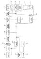
図2には、本実施形態のデジタルカメラ10の回路構成を示すブロック図が示されている。
【0025】
デジタルカメラ10には、撮影レンズ26、シャッタ28及びCCD撮像素子30が備えられている。撮影レンズ26及びシャッタ28を経由してCCD撮像素子30上に結像された被写体像は、CCD撮像素子30によってアナログ画像信号に変換される。ここで、シャッタ28によって、CCD撮像素子30からアナログ画像信号が読み出される際のスミアの発生が抑制される。
【0026】
また、デジタルカメラ10には、閃光装置32が備えられている。この閃光装置32は、低照度時、又は低照度時以外の必要時に閃光を発光し、被写体に補助光を照射する。
【0027】
また、デジタルカメラ10には、アナログ信号処理部34、A/D変換部36、デジタル信号処理部38、テンポラリメモリ40、圧縮伸長部42、内蔵メモリ(又はメモリカード)44、画像モニタ46、及び駆動回路48が備えられている。
【0028】
CCD撮像素子30は、駆動回路48内のタイミング発生回路(図示省略)によって発生されたタイミングで駆動され、アナログ画像信号を出力する。また、駆動回路48には、撮影レンズ26、シャッタ28等を駆動する駆動回路も含まれている。
【0029】
CCD撮像素子30から出力されたアナログ画像信号は、アナログ信号処理部34でアナログ信号処理され、A/D変換部36でA/D変換され、そして、デジタル信号処理部38でデジタル信号処理される。デジタル信号処理されたデジタル画像データは、テンポラリメモリ40に一時的に格納される。
【0030】
テンポラリメモリ40に格納されたデジタル画像データは、圧縮伸長部42で圧縮されて内蔵メモリ(又はメモリカード)44に記録される。尚、撮影モードによっては、圧縮の過程を省いて内蔵メモリ44に直接記録しても良い。そして、テンポラリメモリ40に格納されたデジタル画像データは画像モニタ46に読み出され、画像モニタ46に被写体像が映し出される。
【0031】
また、デジタルカメラ10には、デジタルカメラ10全体の制御を司るCPU50、ズーム操作スイッチ等を含む操作スイッチ群52、及びシャッタボタン54が備えられている。操作スイッチ群52を操作して所望の撮影状態に設定し、シャッタボタン54を押下することによって、写真撮影が行われる。
【0032】
また、デジタルカメラ10には、2次電池51、コンバータ53、及び燃料電池16が備えられており、デジタルカメラ10を構成する各部は、2次電池51にバッファされた電気エネルギーで作動される。この2次電池51にバッファされた電気エネルギーが不足していると、CPU50は、コンバータ53を作動させて燃料電池16を発電させる。そして、燃料電池16から電気エネルギーが供給されて2次電池51の充電が完了すると、コンバータ53の作動を停止させて燃料電池16の発電を停止させる。
【0033】
図3に示すように、デジタルカメラ10の背面には、ファインダ56、ファインダLED58、撮影/再生モード選択スイッチ60、撮影モード選択ダイヤル62、マルチファンクションの十字キー64、カメラの動作モードや十字キー64の機能等を文字やアイコンで表示するドットマトリクスの液晶表示機66、バックスイッチ68、メニュー/OKスイッチ70、画像モニタ46、及びスピーカ72等が設けられている。
【0034】
また、デジタルカメラ10の上面には、電源スイッチ74及びシャッターボタン54が設けられ、デジタルカメラ10の側面には、音声/映像(A/V)出力端子76、デジタル(USB)端子78、及びDC入力端子80が設けられている。
【0035】
デジタルカメラ10は、撮影/再生モード選択スイッチ60によって撮影モード又は再生モードが選択できるようになっており、撮影モード時には撮影モード選択ダイヤル62によってマニュアル撮影、オート撮影、動画、ボイスレコーダー等の各モードが選択できるようになっている。尚、ボイスレコーダは、音声のみを記録するモードである。また、静止画の撮影後に音声を記録することができるボイスメモ機能を有している。
【0036】
画像モニタ46は、電子ビューファインダとして使用できると共に、内蔵メモリ(又はメモリカード)44から読み出した再生画像等を表示することができる。また、画像モニタ46は、撮影可能コマ数や再生コマ番号の表示、ストロボ発光の有無、マクロモード表示、記録画質(クオリティー)表示、画素数表示等の情報も表示され、更に各種のメニュー等がメニュー/OKボタン70や十字キー64の操作に応じて表示される。
【0037】
図4に示すように、デジタルカメラ10の上面には、燃料タンク12を収納部14へ出し入れするためのスライド式の蓋82が設けられているが、この蓋82とは別の蓋84が、デジタルカメラ10の前面に燃料タンク12に面して設けられている。この蓋84が開かれると、燃料タンク12の全体がデジタルカメラ10の前面に露出される。
【0038】
蓋84には、燃料タンク12の燃料貯留部12Aに面した燃料ゲージ窓86と、水回収部12Bに面した副生成物ゲージ窓88とが設けられている。燃料ゲージ窓86と副生成物ゲージ窓88は、デジタルカメラ10が横向き(通常の向き)になっている時に、縦方向に延出する細長い透明性の窓である。また、燃料タンク12は透明性の容器である。このため、燃料ゲージ窓86から燃料の残量を確認でき、水除き窓88から水の量を確認できる。
【0039】
しかし、図5に示すように、デジタルカメラ10を縦向きにした場合、燃料ゲージ窓86から燃料貯留部12A内の燃料の液面が見えなくなり、また、副生成物ゲージ窓88から水回収部12B内の水の液面が目えなくなるので、燃料、水の量を確認できなくなる。
【0040】
このため、図6、図7に示すように、蓋84が開閉可能となっており、燃料ゲージ窓86、及び副生成物ゲージ窓88からは目えない範囲まで、燃料、水が見えるようになっている。従って、デジタルカメラ10の向きに関わらず、燃料の残量、回収された水の量を確認できる。
【0041】
また、図8に示すように、蓋84の裏面の一端部にはヒンジ90が設けられ、他端部にはコ字状のフック92が設けられている。このフック92には、ロック軸94の一端部が挿入されており、蓋84が開かなくなっている。ロック軸94は、ロック軸94の延出方向に移動可能に支持され、ロック軸94の他端部にはラック94Aが形成されている。このラック94Aには、モータ96がギア96Aを噛合させている。
【0042】
これによって、モータ96が作動されるとロック軸94がフック92に出入し、蓋84がロックされ、又は図9に示すように、蓋84はロック解除され、開閉可能となる。
【0043】
この蓋84は、撮影レンズ26に近設されており、蓋84が開かれると撮影レンズ26の前面が塞がれる。このため、CPU50は、撮影/再生モード選択スイッチ60によって撮影モードが選択されると、モータ96を作動させてロック軸94をフック92に挿入させ、蓋84が開かないようにする。これによって、撮影時に蓋84が撮影レンズ26の前を遮ってしまうことはない。尚、蓋84をロックするのは、撮影時に限らず、充電時等に行ってもよい。
【0044】
次に、第2の実施形態について説明する。
【0045】
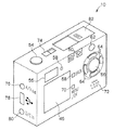
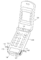
図10、図11に示すように、カメラ101を備えるカメラ付携帯電話(以下、携帯電話)100には、メタノール水溶液(CH3COOH+H2O)が充填された燃料タンク102が、携帯電話100の本体側100Aに設けられた収納部104へ上方から装填される。収納部104の底部には、メタノール水溶液と酸素(O2)の化学反応によって発電を起し、副生成物として水(H2O)を生成するメタノール直接型燃料電池(以下、燃料電池)106が備えられている。
【0046】
燃料タンク102と燃料電池106は、薄型の本体100Aに合わせて薄型の筐体となっている。燃料タンク102の燃料貯留部102A、燃料電池106の燃料極106Aは、本体100Aの一方の側面に面して設けられ、燃料タンク102の水回収部102B、燃料電池106の空気極106Bは、本体100Aの他方の側面に面して設けられている。
【0047】
また、燃料タンク102を収納部104へ出し入れするための蓋107とは別の蓋108が、本体100Aの一方の側面に、燃料貯留部102Aに面して開閉可能に設けられている。この蓋108には、ゲージとなる燃料ゲージ窓110が設けられている。燃料ゲージ窓110は、収納部104の上部から底部へ延出する縦長の透明な窓である。また、燃料タンク102は透明性の容器であるため、燃料ゲージ窓110から燃料貯留部102A内の燃料の残量を確認できる。
【0048】
そして、蓋108が開かれると、燃料収納部102Aの全体が表面に露出されるので、携帯電話100がどのような向きになっていようと、燃料の残量を確認できる。また、本体100Aの他方の側面には、水回収部102Bに面して蓋112や副生成物ゲージ窓114が設けられており、水回収部102Bに回収された水の量を確認できるようになっている。
【0049】
なお、本実施形態では、デジタルカメラ10、カメラ付携帯電話100を例にとって説明したが、アナログカメラやノートパソコン等の他の機器にも適用可能である。
【0050】
また、メタノール直接型燃料電池について説明したが、他の種類の燃料電池にも適用可能である。
【0051】
【発明の効果】
本発明は上記構成としたので、燃料電池搭載機器の向きに関わらず、燃料の残量を確認できる。
【図面の簡単な説明】
【図1】第1の実施形態のデジタルカメラを示す斜視図である。
【図2】第1の実施形態のデジタルカメラの回路構成を示すブロック図である。
【図3】第1の実施形態のデジタルカメラを示す斜視図である。
【図4】第1の実施形態のデジタルカメラを示す斜視図である。
【図5】第1の実施形態のデジタルカメラを示す斜視図である。
【図6】第1の実施形態のデジタルカメラを示す斜視図である。
【図7】第1の実施形態のデジタルカメラを示す斜視図である。
【図8】第1の実施形態のデジタルカメラのロック手段を示す斜視図である。
【図9】第1の実施形態のデジタルカメラのロック手段を示す斜視図である。
【図10】第2の実施形態のカメラ付携帯電話を示す斜視図である。
【図11】第2の実施形態のカメラ付携帯電話を示す斜視図である。
【図12】第2の実施形態のカメラ付携帯電話を示す斜視図である。
【図13】従来例の燃料電池を搭載するデジタルカメラを示す平面図である。
【符号の説明】
10 デジタルカメラ(燃料電池搭載機器)
12 燃料タンク
12A 燃料貯留部(燃料タンク)
12B 水回収部(副生成物タンク)
16 燃料電池
50 CPU(制御手段)
84 蓋(燃料覗き蓋)
86 燃料ゲージ窓
88 副生成物ゲージ窓
92 フック(ロック手段)
94 ロック軸(ロック手段)
96 モータ(ロック手段)
100 カメラ付携帯電話(燃料電池搭載機器)
102 燃料タンク
102A 燃料貯留部(燃料タンク)
102B 水回収部(副生成物タンク)
106 燃料電池
108 蓋(燃料覗き蓋)
110 燃料ゲージ窓
112 蓋(副生成物覗き蓋)
114 副生成物ゲージ窓[0001]
BACKGROUND OF THE INVENTION
The present invention relates to a fuel cell-equipped device that mounts a fuel cell.
[0002]
[Prior art]
Conventionally, a device equipped with a fuel cell has been devised (see, for example, Patent Document 1 or 2). In Patent Documents 1 and 2, means for detecting the remaining amount of fuel is disclosed, but both are complicated mechanisms and expensive.
[0003]
As a simple mechanism, it is conceivable to provide a gauge window in the device casing that allows the fuel to be directly observed. However, as shown in FIG. That is, when the
[0004]
[Patent Document 1]
JP-A-9-213359 [Patent Document 2]
Japanese Patent Laid-Open No. 2003-36879
[Problems to be solved by the invention]
The present invention has been made in consideration of the above-described facts, and an object thereof is to provide a configuration in which the remaining amount of fuel can be confirmed regardless of the orientation of the fuel cell-equipped device.
[0006]
[Means for Solving the Problems]
The fuel cell-equipped device according to claim 1, a transparent fuel tank that stores fuel, a fuel cell that is supplied with fuel from the fuel tank and generates electric power consumed by the device, and the fuel tank. A fuel peep lid for checking the remaining amount of fuel in the fuel tank, a fuel gauge window for checking the liquid level of the fuel provided on the fuel peep lid, It is characterized by having.
[0007]
In the fuel cell-equipped device according to the first aspect, the fuel stored in the fuel tank is supplied from the fuel tank to the fuel cell, and electric power consumed by the device is generated. Since the fuel tank is transparent and the stored fuel can be seen through, the liquid level of the fuel in the fuel tank can be confirmed from the fuel gauge window, and the remaining amount of fuel can be confirmed.
[0008]
Here, if the fuel cell-equipped device is a device with a non-constant orientation, such as a camera, depending on the orientation of the device and the remaining amount of fuel, the fuel level in the fuel tank cannot be seen from the fuel gauge window, and the remaining fuel The amount cannot be confirmed.
[0009]
However, the fuel gauge window is provided on a fuel peep lid that is openable and closable facing the fuel tank, and when the fuel peep lid is opened, the fuel tank is exposed to the surface. For this reason, the remaining amount of fuel can be confirmed regardless of the orientation of the device.
[0010]
The fuel cell-equipped device according to claim 2 is the fuel cell-equipped device according to claim 1, wherein the fuel cell-equipped device is provided facing the fuel peep lid and collects a by-product generated by the fuel cell. A transparent by-product tank; and a by-product gauge window provided on the fuel peep lid for confirming a liquid level of the by-product in the by-product tank. .
[0011]
In the fuel cell-equipped device according to the second aspect, the by-product generated by the fuel cell is collected in the by-product tank. The by-product tank is transparent, and the recovered by-product can be seen through, so the liquid level of the by-product in the by-product tank can be confirmed from the by-product gauge window, and the amount of by-product can be reduced. I can confirm.
[0012]
The by-product gauge window is provided in the by-product sight cover, and this by-product sight cover is provided so as to be openable and closable so as to face the by-product tank. The product tank is exposed on the surface. For this reason, the amount of by-products can be confirmed regardless of the orientation of the device and the amount of by-products.
[0013]
A fuel cell-equipped device according to a third aspect is the fuel cell-equipped device according to the first aspect, wherein a transparent by-product tank that collects a by-product generated by the fuel cell, and the by-product A by-product viewing lid for checking the amount of by-products in the by-product tank, and a by-product viewing lid provided to the product tank so as to be openable and closable. And a by-product gauge window for confirming the liquid level of the liquid.
[0014]
In the fuel cell-equipped device according to the third aspect, the fuel viewing lid and the byproduct viewing lid are provided separately. As a result, the degree of freedom of arrangement of the fuel sight cover and the by-product sight cover increases, and it can be applied to various devices.
[0015]
The fuel cell-equipped device according to
[0016]
In the fuel cell-equipped device according to the fourth aspect, when the device is in a predetermined state such as during photographing, the control device activates the locking device, and the fuel viewing lid or the byproduct viewing lid is locked in the closed state. For this reason, it is possible to prevent the fuel sight cover or the by-product sight cover from being accidentally opened when it is not convenient to open the fuel sight cover or the by-product sight cover when the device is activated.
[0017]
A fuel cell-equipped device according to a fifth aspect is the fuel cell-equipped device according to the fourth aspect, wherein the control means activates the locking means during photographing.
[0018]
In the fuel cell-equipped device according to the fifth aspect, the lock means is actuated by the control means at the time of photographing, and the fuel sight cover or the byproduct sight cover is locked in the closed state. For this reason, for example, it can be prevented that an open fuel peep lid blocks the front of the lens and the subject is not photographed.
[0019]
The fuel cell-equipped device according to claim 6 is the fuel cell-equipped device according to
It has a lock shaft reciprocated by the motor, and a hook provided on the back surface of the fuel peep lid or the byproduct peep lid and engaged with the lock shaft.
[0020]
In the fuel cell-equipped device according to claim 6, the lock shaft is reciprocated by a motor operated by the control means, and engages with a hook provided on the back surface of the fuel sight cover or the byproduct sight cover, or Get out of the hook. When the lock shaft is engaged with the hook, the fuel peep lid or by-product peep lid is locked, and when the lock shaft is pulled out of the hook, the fuel peep lid or by-product peep lid can be opened and closed. .
[0021]
DETAILED DESCRIPTION OF THE INVENTION
A first embodiment of the present invention will be described below with reference to the drawings.
[0022]
As shown in FIG. 1, in a
[0023]
The
[0024]
FIG. 2 is a block diagram showing a circuit configuration of the
[0025]
The
[0026]
The
[0027]
The
[0028]
The CCD
[0029]
The analog image signal output from the CCD
[0030]
The digital image data stored in the temporary memory 40 is compressed by the compression /
[0031]
The
[0032]
Further, the
[0033]
As shown in FIG. 3, a
[0034]
A
[0035]
The
[0036]
The image monitor 46 can be used as an electronic viewfinder and can display a reproduced image read from the built-in memory (or memory card) 44. The image monitor 46 also displays information such as the number of frames that can be shot and the number of playback frames, the presence / absence of flash emission, macro mode display, recording image quality (quality) display, pixel number display, and various menus. Displayed in response to the operation of the menu /
[0037]
As shown in FIG. 4, a slide-
[0038]
The
[0039]
However, as shown in FIG. 5, when the
[0040]
For this reason, as shown in FIGS. 6 and 7, the
[0041]
Further, as shown in FIG. 8, a
[0042]
Thus, when the
[0043]
The
[0044]
Next, a second embodiment will be described.
[0045]
As shown in FIGS. 10 and 11, a camera-equipped cellular phone (hereinafter, cellular phone) 100 including a
[0046]
The
[0047]
Further, a
[0048]
When the
[0049]
In the present embodiment, the
[0050]
Although the methanol direct fuel cell has been described, the present invention can be applied to other types of fuel cells.
[0051]
【The invention's effect】
Since the present invention has the above configuration, the remaining amount of fuel can be confirmed regardless of the orientation of the fuel cell-equipped device.
[Brief description of the drawings]
FIG. 1 is a perspective view illustrating a digital camera according to a first embodiment.
FIG. 2 is a block diagram illustrating a circuit configuration of the digital camera according to the first embodiment.
FIG. 3 is a perspective view showing the digital camera of the first embodiment.
FIG. 4 is a perspective view showing the digital camera of the first embodiment.
FIG. 5 is a perspective view showing the digital camera of the first embodiment.
FIG. 6 is a perspective view showing the digital camera of the first embodiment.
FIG. 7 is a perspective view showing the digital camera of the first embodiment.
FIG. 8 is a perspective view showing locking means of the digital camera of the first embodiment.
FIG. 9 is a perspective view showing locking means of the digital camera of the first embodiment.
FIG. 10 is a perspective view showing a camera-equipped mobile phone according to a second embodiment.
FIG. 11 is a perspective view showing a camera-equipped mobile phone according to a second embodiment.
FIG. 12 is a perspective view showing a camera-equipped mobile phone according to a second embodiment.
FIG. 13 is a plan view showing a digital camera equipped with a conventional fuel cell.
[Explanation of symbols]
10 Digital camera (equipment with fuel cell)
12
12B Water recovery unit (by-product tank)
16 Fuel cell 50 CPU (control means)
84 Lid (Fuel Peeping Lid)
86
94 Lock shaft (locking means)
96 Motor (locking means)
100 Mobile phone with camera (equipment with fuel cell)
102
102B Water recovery unit (by-product tank)
106
110
114 By-product gauge window
Claims (6)
前記燃料タンクから燃料を供給され、機器で消費される電力を発電する燃料電池と、
前記燃料タンクに面して開閉可能に設けられ、前記燃料タンク内の燃料の残量を確認するための燃料覗き蓋と、
前記燃料覗き蓋に設けられ、燃料の液面水位を確認するための燃料ゲージ窓と、
を有することを特徴とする燃料電池搭載機器。A transparent fuel tank for storing fuel,
A fuel cell that is supplied with fuel from the fuel tank and generates electric power consumed by the device;
A fuel peep lid that is provided so as to be openable and closable facing the fuel tank, and for checking the remaining amount of fuel in the fuel tank;
A fuel gauge window provided on the fuel peep lid for checking the liquid level of the fuel;
A fuel cell-equipped device comprising:
前記燃料覗き蓋に設けられ、前記副生成物タンク内の副生成物の液面水位を確認するための副生成物ゲージ窓と、
を有することを特徴とする請求項1に記載の燃料電池搭載機器。A transparent by-product tank that is provided facing the fuel peep lid and collects by-products generated in the fuel cell;
A by-product gauge window provided on the fuel peep lid for confirming the liquid level of the by-product in the by-product tank;
The fuel cell-equipped device according to claim 1, comprising:
前記副生成物タンクに面して開閉可能に設けられ、前記副生成物タンク内の副生成物の量を確認するための副生成物覗き蓋と、
前記副生成物覗き蓋に設けられ、副生成物の液面水位を確認するための副生成物ゲージ窓と、
を有することを特徴とする請求項1に記載の燃料電池搭載機器。A transparent by-product tank that collects by-products generated in the fuel cell;
A by-product viewing lid for checking the amount of the by-product in the by-product tank provided to be openable and closable facing the by-product tank;
A by-product gauge window provided on the by-product viewing lid for confirming the liquid level of the by-product;
The fuel cell-equipped device according to claim 1, comprising:
前記機器が所定の作動状態の時に前記ロック手段を作動させる制御手段と、
を有することを特徴とする請求項1乃至3の何れかに記載の燃料電池搭載機器。Lock means for locking the fuel peep lid or the byproduct peep lid in a closed state;
Control means for operating the locking means when the device is in a predetermined operating state;
4. The fuel cell-equipped device according to claim 1, wherein:
前記制御手段によって作動されるモータと、
前記モータによって往復動されるロック軸と、
前記燃料覗き蓋又は前記副生成物覗き蓋の裏面に設けられ、前記ロック軸が係合するフックと、
を有することを特徴とする請求項4又は5に記載の燃料電池搭載機器。The locking means is
A motor operated by the control means;
A lock shaft reciprocated by the motor;
A hook provided on a back surface of the fuel peep lid or the by-product peep lid and engaged with the lock shaft;
The fuel cell-equipped device according to claim 4, wherein the device has a fuel cell.
Priority Applications (1)
| Application Number | Priority Date | Filing Date | Title |
|---|---|---|---|
| JP2003131251A JP2004335331A (en) | 2003-05-09 | 2003-05-09 | Apparatus equipped with fuel cell |
Applications Claiming Priority (1)
| Application Number | Priority Date | Filing Date | Title |
|---|---|---|---|
| JP2003131251A JP2004335331A (en) | 2003-05-09 | 2003-05-09 | Apparatus equipped with fuel cell |
Publications (1)
| Publication Number | Publication Date |
|---|---|
| JP2004335331A true JP2004335331A (en) | 2004-11-25 |
Family
ID=33506481
Family Applications (1)
| Application Number | Title | Priority Date | Filing Date |
|---|---|---|---|
| JP2003131251A Pending JP2004335331A (en) | 2003-05-09 | 2003-05-09 | Apparatus equipped with fuel cell |
Country Status (1)
| Country | Link |
|---|---|
| JP (1) | JP2004335331A (en) |
Cited By (4)
| Publication number | Priority date | Publication date | Assignee | Title |
|---|---|---|---|---|
| JP2006189555A (en) * | 2005-01-05 | 2006-07-20 | Sharp Corp | Flat panel display device with fuel cell mounted |
| WO2007010815A1 (en) | 2005-07-15 | 2007-01-25 | Kabushiki Kaisha Toshiba | Fuel battery |
| CN100401570C (en) * | 2005-04-08 | 2008-07-09 | 三洋电机株式会社 | Liquid tank and fuel cell system with fuel monitoring |
| JP2010082580A (en) * | 2008-10-01 | 2010-04-15 | Ulvac Japan Ltd | Method of applying microparticles |
-
2003
- 2003-05-09 JP JP2003131251A patent/JP2004335331A/en active Pending
Cited By (6)
| Publication number | Priority date | Publication date | Assignee | Title |
|---|---|---|---|---|
| JP2006189555A (en) * | 2005-01-05 | 2006-07-20 | Sharp Corp | Flat panel display device with fuel cell mounted |
| JP4568122B2 (en) * | 2005-01-05 | 2010-10-27 | シャープ株式会社 | Flat panel display device with fuel cell |
| CN100401570C (en) * | 2005-04-08 | 2008-07-09 | 三洋电机株式会社 | Liquid tank and fuel cell system with fuel monitoring |
| WO2007010815A1 (en) | 2005-07-15 | 2007-01-25 | Kabushiki Kaisha Toshiba | Fuel battery |
| JPWO2007010815A1 (en) * | 2005-07-15 | 2009-01-29 | 株式会社東芝 | Fuel cell |
| JP2010082580A (en) * | 2008-10-01 | 2010-04-15 | Ulvac Japan Ltd | Method of applying microparticles |
Similar Documents
| Publication | Publication Date | Title |
|---|---|---|
| JP4035488B2 (en) | Imaging device | |
| JP4048334B2 (en) | Electronic camera | |
| JP3948003B2 (en) | Portable electronic devices | |
| JP2005278058A (en) | Portable electronic apparatus | |
| US20070280671A1 (en) | Image pickup apparatus | |
| JP4301241B2 (en) | Digital camera and power supply control method thereof | |
| JP2004335331A (en) | Apparatus equipped with fuel cell | |
| JP2008011232A (en) | Digital camera | |
| JP2006323298A (en) | Cradle with waterproof function | |
| JP4732387B2 (en) | Display device, display control method thereof, and imaging device | |
| JP2006060585A (en) | Digital camera | |
| JP4581780B2 (en) | Display device with touch panel | |
| JP2005092070A (en) | Underwater camera case, fuel cell loading waterproof camera, and fuel cell loading camera | |
| JP4213528B2 (en) | Fuel cell equipment and fuel tank | |
| JP4348111B2 (en) | Fuel cell equipment | |
| JP2007214774A (en) | Imaging apparatus | |
| JP2006235077A (en) | Lens interchangeable camera | |
| JP2005019291A (en) | Fuel cell mounted apparatus | |
| JP4437907B2 (en) | Fuel cell equipment | |
| JP2004193642A (en) | Digital camera | |
| JPH11282071A (en) | Electronic still camera | |
| JP4012471B2 (en) | Digital camera | |
| JP2004207899A (en) | Digital camera | |
| JP2004302353A (en) | Cradle with waterproof function | |
| JP4213519B2 (en) | Fuel cell equipment and fuel tank |