JP2004334169A - Beam multiplexing element, beam multiplexing method, beam separating element, beam separating method, and exciting light output device - Google Patents
Beam multiplexing element, beam multiplexing method, beam separating element, beam separating method, and exciting light output device Download PDFInfo
- Publication number
- JP2004334169A JP2004334169A JP2003415404A JP2003415404A JP2004334169A JP 2004334169 A JP2004334169 A JP 2004334169A JP 2003415404 A JP2003415404 A JP 2003415404A JP 2003415404 A JP2003415404 A JP 2003415404A JP 2004334169 A JP2004334169 A JP 2004334169A
- Authority
- JP
- Japan
- Prior art keywords
- phase difference
- beams
- birefringent material
- incident
- material portion
- Prior art date
- Legal status (The legal status is an assumption and is not a legal conclusion. Google has not performed a legal analysis and makes no representation as to the accuracy of the status listed.)
- Pending
Links
Images


Abstract
Description
本発明は、複数の光ビームを合波、または分離し、例えば出射光を励起光源として利用するビーム合波素子、ビーム合波方法、ビーム分離素子、ビーム分離方法及び励起光出力装置に関わる。 The present invention relates to a beam combining element, a beam combining method, a beam separating element, a beam separating method, and a pumping light output device that combine or separate a plurality of light beams and use, for example, outgoing light as an excitation light source.
半導体レーザダイオード(LD)の出射光を利用し、光源の出射位置や出射方向を自由に設置できる点で実用上非常に利用し易いファイバー出力励起光源の需要が増している。LDからの出射光を、ファイバーを介して出射させるピッグテールレーザとも呼ばれるファイバー出力励起光源の用途としては、光通信分野を始め、加工・検査やレーザ励起などの産業用、医療用、印刷などの民生用などさまざまな分野が挙げられる。
このような光源としては、出力や輝度が大きい程、また小型であればある程使用可能用途が拡大する。
また、出射方法にファイバーを用いない場合でも、光源自体が小型で高輝度であれば、この光源を設置できる範囲、ひいては応用分野が広がる。
There is an increasing demand for a fiber output pump light source that is very easy to use practically because the output position and the output direction of the light source can be freely set by using the output light of a semiconductor laser diode (LD). The fiber output pumping light source, also called a pigtail laser, that emits the light emitted from an LD through a fiber is used in the optical communication field, as well as in industrial, medical, printing, and other industries such as processing and inspection and laser excitation. And various fields.
As such a light source, as the output and the luminance are larger, and as the light source is smaller, the usable applications are expanded.
Further, even when a fiber is not used for the light emitting method, if the light source itself is small and has high brightness, the range in which the light source can be installed, and the application field is widened.
光源の出力及び輝度を増加させるためには、LDへの入力電流を増加させると信頼性を犠牲にしてしまうので、同じLD光源を複数合波するのが簡便である。小型化するためには、光源装置の内部部品点数をできるだけ減らし、精密調整を可能な限り不要とすることが望ましい。 In order to increase the output and the brightness of the light source, if the input current to the LD is increased, reliability is sacrificed. Therefore, it is convenient to combine a plurality of the same LD light sources. In order to reduce the size, it is desirable to reduce the number of internal parts of the light source device as much as possible and to make precision adjustment as unnecessary as possible.
例えば、2つのLD出射光のビーム合波には、偏光ビームスプリッタ(PBS)がよく用いられる(例えば特許文献1参照。)。
上記特許文献1には、LDの出射方向を直交する方向に設置して、PBSにより偏波面を合わせて合波する装置が提案されている。
For example, a polarization beam splitter (PBS) is often used for beam combining of two LD output lights (for example, see Patent Document 1).
しかしながら、このようにPBSを用いる方法で合波効率を高めるためには、互いに直交する偏光の2つのビームについて、ビーム合波部分でのビーム方向とその重なりを十分に大きくしなければならず、また一般にPBSの入射角の許容角度が小さいため、精密な光学調整が必要となる。
更にPBSを用いる場合、このPBSに入射させるビーム方向を異ならせる必要がある。例えば上記特許文献1に記載されているように立方体型のPBSを用いる場合は入射方向が直交する方向となる。従って、電極や冷却素子が個別に配設されるLDを配置すると、合波素子としての小型化は困難となる。
However, in order to increase the multiplexing efficiency by using the PBS in this way, for two beams having polarizations orthogonal to each other, the beam direction and the overlap at the beam multiplexing portion must be sufficiently large. In addition, since the allowable angle of incidence of the PBS is generally small, precise optical adjustment is required.
Further, when using a PBS, it is necessary to make the beam direction incident on the PBS different. For example, when a cubic PBS is used as described in
また、多数のLDを配列したいわゆるアレイ型LDのように、LD素子を近接配置した一体型のLD光源を用いても、ビームの出射方向を変換するための折り返しミラーとその配置の精密調整が必要となる。しかもこのように折り返しミラーを用いる場合は、光路長が異なることから、例えばマイクロレンズを用いる等の方法により完全にコリメートビームにして合波しなければならないという不都合も生じる。 In addition, even when an integrated LD light source in which LD elements are arranged close to each other is used, such as a so-called array type LD in which a large number of LDs are arranged, a folding mirror for changing a beam emission direction and precise adjustment of the arrangement are required. Required. In addition, in the case of using the folding mirror as described above, since the optical path lengths are different, there is a disadvantage that the beam must be completely collimated and multiplexed by a method such as using a microlens.
他のビーム合波方法としては、プリズムを用いる方法が挙げられる( 例えば特許文献2及び3参照。) 。
しかしながら上記特許文献2及び3に記載されているようにプリズムを用いて合波する場合は、プリズムとレンズが必要であったり、合波位置の精密な調整が必要であったり、また合波後のビーム進行方向が2つの入射ビームと異なるという点が問題となる。その他、光通信分野で用いられる導波路を用いた光結合は、パワー伝送を目的としていないのでパワー密度の高い用途には信頼性及び効率の点で適さない。
As another beam combining method, there is a method using a prism (for example, see
However, when multiplexing is performed using a prism as described in
一方、複屈折材料に任意の偏光方向の光を入射すると、その偏光方向によって、直進するビーム成分とビームエネルギーの伝搬方向が直進方向からずれるウォークオフ成分に分かれるため、複屈折素子は光通信分野などでビームを分離するビームスプリッタ(光分波器)としてよく使われている。入射ビームの偏光が互いに垂直であれば、このような複屈折素子における伝搬方向を逆にしたビーム合波を用いることができる(例えば特許文献4及び5参照。)。
On the other hand, when light with an arbitrary polarization direction is incident on the birefringent material, the birefringent element is used in the optical communication field because the beam component traveling straight and the propagation direction of the beam energy are separated from the walk-off component deviating from the rectilinear direction depending on the polarization direction. It is often used as a beam splitter (optical demultiplexer) for splitting a beam by using such a method. If the polarizations of the incident beams are perpendicular to each other, beam multiplexing in which the propagation direction in such a birefringent element is reversed can be used (for example, see
この場合に必要とされる複屈折素子への入射光は近接する平行ビームである。しかし、光源に2つの近接した同じLDを並べて用いる場合は、その偏光方向が等しいため複屈折素子に入射する前に片方のLDビームだけ偏光方向を90度回転させる必要がある。 The light incident on the birefringent element required in this case is an adjacent parallel beam. However, when two adjacent LDs are used side by side with a light source, their polarization directions are equal, so that it is necessary to rotate the polarization direction of one LD beam by 90 degrees before entering the birefringent element.
入射ビームを任意の直線偏光方向に変換する手段としては、特定の直線偏光方向の光を出射するいわゆる偏波面保存ファイバーを用いることができる。しかしながら、LD光を通常10μm程度以下とコア径の小さい偏波面保存ファイバーにカップリングするためには、微小なレンズとその精密な光学調整が必要である。また、偏波面保存ファイバーを含むシングルモードファイバーはそのコア径の小ささなどからハイパワー伝送用途にはあまり適さない。 As a means for converting an incident beam into an arbitrary linear polarization direction, a so-called polarization-maintaining fiber that emits light in a specific linear polarization direction can be used. However, in order to couple the LD light to a polarization preserving fiber having a small core diameter of usually about 10 μm or less, a minute lens and its precise optical adjustment are required. Also, single mode fibers including polarization maintaining fibers are not very suitable for high power transmission applications due to their small core diameter.
更に、偏波面保存ファイバーからの出射光を、近接した所望のビーム間隔を有する平行ビームにする工夫とその調整が必要となる(例えば特許文献6、7、8及び9参照。)。複屈折材料のウォークオフ量はその伝搬長さに比例するため、入射ビームが互いに離れるほど素子が大きくなってしまうためである。
Further, it is necessary to devise a method of converting the light emitted from the polarization-maintaining fiber into a parallel beam having a desired desired beam interval and to adjust the parallel beam (for example, see
ウォークオフ量は複屈折性の大きな材料、例えばYVO4 でも長さ1mmに対し100μmときわめて微小な量であり、例えば5mmの長さの複屈折素子でビーム合波するためには、入射ビーム間隔を500μmに近接させなければならない。適切なファイバー長さや曲げ(角度)に対応してLD、複屈折素子を配置しなければならない点でも、装置の小型化に限界がある。 The walk-off amount is a very small amount of 100 μm per 1 mm in length for a material having a large birefringence such as YVO 4. For example, in order to combine beams with a birefringent element having a length of 5 mm, the distance between incident beams is required. Must be close to 500 μm. There is also a limit to the miniaturization of the device in that an LD and a birefringent element must be arranged corresponding to an appropriate fiber length and bending (angle).
LDからの出射ビームの偏光方向を変換するもう一つの方法として、例えば位相差板、すなわち1/2波長板、1/4波長板等のいわゆる波長板が挙げられる。しかしながら、通常の使用法では、二つの近接したLDからの光のうち片方のビームだけを波長板に入射させるためには、波長板素子の端まで利用することとなる。LD偏光方向や複屈折素子結晶軸と波長板の進相軸との回転角調整が必要であり、波長板を固定する部材、いわゆるマウントが必要となる。しかしながら、上述したように波長板の端まで利用する場合はこのマウントがビーム光路を遮る可能性があり、その微調整を行うことは製造工程における作業性の低下を招き、生産性の向上、コストの低減化を図り難いという問題がある。 As another method for changing the polarization direction of the beam emitted from the LD, for example, there is a so-called wave plate such as a phase difference plate, that is, a half-wave plate or a quarter-wave plate. However, in a normal usage, in order to make only one beam of the light from two adjacent LDs incident on the wave plate, the light is used up to the end of the wave plate element. It is necessary to adjust the rotation direction of the LD polarization direction and the crystal axis of the birefringent element and the fast axis of the wave plate, and a member for fixing the wave plate, that is, a so-called mount is required. However, as described above, when the end of the wave plate is used, this mount may block the beam optical path, and fine adjustment thereof causes a reduction in workability in a manufacturing process, and improves productivity and costs. There is a problem that it is difficult to reduce the noise.
本発明は、上述したような状況に鑑み、LD等の光源からの光をビーム合波し、小型で高輝度、且つ部品点数が少なく光学調整の簡単なビーム合波素子を実現することにより、特に、ファイバーアンプレーザ等の励起光源に用いて好適な、光源の輝度が高く、パワー伝送に有利なビーム合波素子、ビーム合波方法を提供し、またこれを利用したビーム分離素子、ビーム分離方法及び励起光出力装置を提供することを目的とする。 The present invention has been made in view of the above-described situation, by beam combining light from a light source such as an LD, and realizing a beam combining element that is small, has high luminance, has a small number of parts, and has a simple optical adjustment. In particular, the present invention provides a beam multiplexing element and a beam multiplexing method which are suitable for use as an excitation light source such as a fiber amplifier laser and have a high light source brightness and are advantageous for power transmission. It is an object to provide a method and an excitation light output device.
本発明によるビーム合波素子及びビーム合波方法は、少なくとも複屈折材料部と、この複屈折材料部のビーム入射端面の少なくとも一部に配置された位相差部とより構成し、複屈折材料部に、伝搬方向がほぼ平行で且つほぼ同一偏光とされる第1及び第2のビームもしくはビーム群を入射させ、第1又は第2のビームもしくはビーム群のうちの少なくとも一方のビームもしくはビーム群が位相差部を介して複屈折材料部に入射されて位相差部により偏光方向が変換されて、第1又は第2のビームもしくはビーム群のうち少なくとも一方のビームもしくはビーム群の複屈折材料部内での伝搬方向が変換され、第1及び第2のビームもしくはビーム群が、複屈折材料部の出射位置、もしくは例えば複屈折材料部を複数の複屈折素子により構成する場合には、その出射界面又は入射界面において合波されてほぼ同一な方向に出射される構成とする。 A beam combining element and a beam combining method according to the present invention comprise at least a birefringent material portion and a phase difference portion disposed on at least a part of a beam incident end face of the birefringent material portion. First and second beams or beam groups whose propagation directions are substantially parallel and have substantially the same polarization are incident, and at least one beam or beam group of the first or second beam or beam group is The light is incident on the birefringent material portion via the phase difference portion, the polarization direction is changed by the phase difference portion, and at least one of the first or second beam or the beam group is in the birefringent material portion. Is changed, and the first and second beams or the beam groups form the exit position of the birefringent material portion or, for example, the birefringent material portion is constituted by a plurality of birefringent elements. Expediently, a configuration that is emitted substantially the same direction are multiplexed in the outgoing interface or incident surface.
更に本発明によるビーム分離素子及びビーム分離方法は、上述の構成によるビーム合波素子において、ビーム入射方向及び出射方向を逆向きとして用いるものである。
また本発明による励起光出力装置は、上述のビーム合波素子を用いて2つのビームもしくは2群のビームを合波して、これを励起光用出射光として用いる構成とする。
Further, in the beam splitting element and the beam splitting method according to the present invention, the beam multiplexing element having the above-described configuration uses the beam incident direction and the beam emitting direction in opposite directions.
Further, the pumping light output device according to the present invention has a configuration in which two beams or two groups of beams are multiplexed using the above-described beam multiplexing element, and this is used as pumping light emission light.
上述したように、本発明によるビーム合波素子及びビーム合波方法によれば、複屈折材料部のビーム入射端面の少なくとも一部に位相差部を固定配置して構成することによって、同一の偏光方向の入射ビームもしくはビーム群(以下ビーム(群)と記す)のうち一方のビーム(群)の偏光方向を変換して、複屈折材料部において一方のビーム(群)の伝搬方向を変換することによって、複屈折素子の出射位置、もしくは例えば複屈折材料部を複数の複屈折素子により構成する場合には、その入射又は出射界面においてビーム(群)を合波させる構成とすることができる。 As described above, according to the beam multiplexing device and the beam multiplexing method of the present invention, the same polarization is achieved by arranging the phase difference portion fixedly arranged on at least a part of the beam incident end face of the birefringent material portion. Changing the polarization direction of one beam (group) of the incident beam or beam group (hereinafter referred to as beam (group)) in one direction, and changing the propagation direction of one beam (group) in the birefringent material portion Accordingly, in the case where the birefringent element is composed of a plurality of birefringent elements, or where the birefringent material section is composed of a plurality of birefringent elements, the beam (group) can be combined at the entrance or exit interface.
従って、前述したような位相差部の配置調整のための別体の固定部材を用いることなくビーム合波素子を構成することができることから、ビームのけられ等を生じることなくより効率よくビームを合波させることができ、ビーム合波素子の小型化、特性の向上をはかることができる。 Therefore, since the beam multiplexing element can be configured without using a separate fixing member for adjusting the arrangement of the phase difference unit as described above, the beam can be more efficiently emitted without causing beam shading or the like. The beam can be multiplexed, and the size of the beam multiplexing element can be reduced and the characteristics can be improved.
本発明によれば、このようなビーム合波素子を用いることによって、従来に比し小型で高輝度の励起光出力装置を提供することができる。 According to the present invention, by using such a beam multiplexing device, it is possible to provide an excitation light output device that is smaller and has higher luminance than before.
更に、本発明によるビーム分離素子及びビーム分離方法によれば、同様に位相差部と複屈折材料部とを一体化することによって、部品点数の削減、光学的調整を不要とすることによるコストの低減化、また装置の小型化を図ることができる。 Further, according to the beam separation element and the beam separation method according to the present invention, similarly, by integrating the retardation portion and the birefringent material portion, the number of parts can be reduced, and the cost can be reduced by eliminating the need for optical adjustment. It is possible to reduce the size and size of the device.
上述したように、本発明によるビーム合波素子及びビーム合波方法によれば、同一偏光をもつ2つまたは2群のほぼ平行なビームを1つの素子で簡単に合波することができる。更には、光学部品の調整機構の削減や調整作業を省くことができ、生産性の向上、また部品削減と併せてコストの低減化を図ることができる。 As described above, according to the beam multiplexing device and the beam multiplexing method of the present invention, two or two groups of substantially parallel beams having the same polarization can be easily multiplexed by one device. Furthermore, it is possible to omit the adjustment mechanism and adjustment work of the optical component, thereby improving the productivity and reducing the cost as well as the number of components.
また、本発明によるビーム合波素子によれば、入射角に対する許容範囲を従来に比し拡大することができることから、完全なコリメートビームでなくても比較的高い合波効率をもって合波させることができる。また、合波のための精密な光学調整を不要とすることができる。
更に、位相差部と複屈折材料部とが一体化していることから、強度や取り扱い安さの点で信頼性を高めることができる。
Further, according to the beam multiplexing device of the present invention, since the allowable range for the incident angle can be expanded as compared with the related art, it is possible to multiplex with a relatively high multiplexing efficiency even if the beam is not a perfect collimated beam. it can. Also, precise optical adjustment for multiplexing can be eliminated.
Further, since the retardation portion and the birefringent material portion are integrated, reliability can be enhanced in terms of strength and ease of handling.
したがって、LD等の光源からの光を出力する励起光出力装置に用いることによって、小型で高輝度の光源を構成することができる。また部品点数の削減を図ることができて、装置の小型化を図ることができる。 Therefore, by using the present invention in an excitation light output device that outputs light from a light source such as an LD, a compact and high-luminance light source can be configured. Also, the number of parts can be reduced, and the size of the device can be reduced.
また、本発明において、位相差部として1/2波長板を用いる場合は、コストの低減化、製造工程の簡易化を図ることができ、また波長・温度などの許容範囲を拡大する目的で、厚さの薄くなる次数の低い波長板を用いることができる。
これにより、ビーム合波素子を組み込む装置のコストの低減化を図り、小型で高輝度の励起光出力装置等の光出力装置を提供することができる。
Further, in the present invention, when a half-wave plate is used as the phase difference portion, the cost can be reduced, the manufacturing process can be simplified, and the allowable range of wavelength and temperature can be expanded. A low-order wave plate with a reduced thickness can be used.
This makes it possible to reduce the cost of a device incorporating the beam multiplexing element, and to provide a light output device such as a small and high-brightness excitation light output device.
また、複屈折材料部と位相差部との間を接着剤により接着することにより、製造の簡易化、コストの低減化を図ることができる。
また更に、本発明において、複屈折材料部と位相差部とを同一材料により構成することによって、各部の界面における反射光を抑制し、ビーム利用効率を高めることができる。
更に、補助位相差部を位相差部に並置して配置することによって、複屈折材料部の入射端面を保護することができ、また入射端面の表面研磨、厚さ調整などの加工プロセスにおいてばらつきを抑制し、歩留まりの向上を図り、更に取り扱いの簡易化を図って生産性の向上を図ることができる。
Further, by bonding the birefringent material portion and the retardation portion with an adhesive, simplification of manufacturing and reduction in cost can be achieved.
Still further, in the present invention, by configuring the birefringent material portion and the retardation portion with the same material, it is possible to suppress the reflected light at the interface between the respective portions and increase the beam use efficiency.
Further, by arranging the auxiliary retardation portion in juxtaposition with the retardation portion, it is possible to protect the incident end face of the birefringent material section, and to reduce variations in processing processes such as surface polishing and thickness adjustment of the incident end face. Thus, the yield can be improved, the handling can be simplified, and the productivity can be improved.
また、位相差部と補助位相差部とを同一材料により構成することによって、これらの界面での散乱を抑え、ビーム利用効率の向上を図ることができる。
更に、位相差部及び補助位相差部のビーム伝搬方向の物理長をほぼ同一とすることによって、ビーム合波素子内の光路長をほぼ等しくし、発散角をもった入射ビームを用いる場合にはその発散角の拡がりを抑えることができる。
In addition, by forming the retardation portion and the auxiliary retardation portion from the same material, scattering at the interface between them can be suppressed, and the beam use efficiency can be improved.
Further, by making the physical lengths of the phase difference part and the auxiliary phase difference part in the beam propagation direction substantially the same, the optical path length in the beam combining element is made substantially equal, and when an incident beam having a divergence angle is used. The spread of the divergence angle can be suppressed.
また更に、補助位相差部を、光学的等方性を有する材料、もしくは透過板より構成することによって、補助位相差部作製時の結晶光軸合わせ等の光学調整を不要とし、製造の簡易化、コストの低減化を図ることができる。 Further, by forming the auxiliary retardation portion from a material having optical isotropy or a transmission plate, optical adjustment such as crystal optical axis alignment at the time of producing the auxiliary retardation portion is not required, thereby simplifying manufacturing. In addition, cost can be reduced.
更に本発明において、ビーム入射端面又は出射端面に反射防止機能を有する光学膜を設けることによって、ビームの反射を抑え、利用効率を向上させることができる。
また、光源としてレーザダイオードを用いる場合には入射光の偏光方向の調整を不要とし、光学系を簡略化することができて、小型化を図ることができる。
Further, in the present invention, by providing an optical film having an anti-reflection function on the beam incident end face or the output end face, it is possible to suppress the reflection of the beam and improve the utilization efficiency.
When a laser diode is used as the light source, it is not necessary to adjust the polarization direction of the incident light, so that the optical system can be simplified and the size can be reduced.
更にまた、入射端面又は出射端面、もしくはその両方にレンズを形成することによって、より小型化を図り、また各種装置に組み込む場合の取り扱いの簡易化を図ることができる。 Furthermore, by forming a lens on the entrance end face or the exit end face, or both, it is possible to further reduce the size and to simplify the handling when the lens is incorporated into various devices.
また更に本発明によるビーム分離素子及びビーム分離方法によれば、任意の直線偏光を持つ光信号を、同一偏光の光信号に分波することができるので、光通信などにおけるあらゆるビーム分波装置として利用し、分波装置構成の簡略化、小型化、コストの低減化を図ることができる。 Further, according to the beam separation element and the beam separation method of the present invention, an optical signal having an arbitrary linear polarization can be demultiplexed into an optical signal having the same polarization. Utilization can be used to simplify the configuration of the demultiplexer, reduce the size, and reduce the cost.
また本発明による励起光出力装置によれば、小型で高輝度の光源を提供することによって、効率の良いレーザを実現することができる。
特にファイバーアンプレーザまたはファイバーレーザの励起光源として適用することによって、より小型で高輝度のファイバーアンプレーザまたはファイバーレーザを提供することができる。
Further, according to the excitation light output device of the present invention, an efficient laser can be realized by providing a compact and high-luminance light source.
In particular, by applying the present invention as a fiber amplifier laser or an excitation light source for a fiber laser, a fiber amplifier laser or a fiber laser with smaller size and higher luminance can be provided.
以下本発明による実施の形態の各例を、図面を参照して説明するが、本発明は以下の例に限定されるものではなく、その他種々の変形、変更が可能であることはいうまでもない。 Hereinafter, each example of an embodiment according to the present invention will be described with reference to the drawings. However, the present invention is not limited to the following example, and it goes without saying that various other modifications and changes are possible. Absent.
〔第1の実施の形態〕
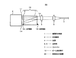
本発明によるビーム合波素子の一例を励起光出力装置に適用した場合の模式的な構成を図1に示す。図1において、1は複屈折材料部で、そのビーム入射端面1Aの少なくとも一部に、位相差部2が固定配置されてビーム合波素子10が構成される。
4はLD等の光源を示す。この例においては、この光源4は、例えば図1の紙面の面内方向に沿うほぼ同一方向の直線偏光を有し、同一方向に伝搬する2つのビームLi1 及びLi2 を出射するものとする。このようなLD光源としては、例えばストライプ状の共振器が平行に2本配列され、即ち活性層に平行な面内に各レーザ素子が並置配列されて、そのビーム出射位置が例えば中心位置間隔で1mm程度とされたLDを用いることができる。
[First Embodiment]
FIG. 1 shows a schematic configuration when an example of the beam multiplexing device according to the present invention is applied to an excitation light output device. In FIG. 1,
この場合、出射したビームLi1 及びLi2 のLD素子端面付近の光スポット形状は通常横長となる。このビームLi1 及びLi2 が、ビーム合波素子10内において、位相差部2による偏光回転と複屈折材料部3のウォークオフ作用により、複屈折材料部3を通過後に合波して、1つの出射光Loとして出射されるように、偏光方向、位相差部2の厚さ及び進相軸方向、更に複屈折材料部1の結晶軸方向及び長さなどを選定する。
In this case, the light spot shape of the emitted beams Li1 and Li2 near the end face of the LD element is usually horizontally long. The beams Li1 and Li2 combine in the
出射ビームLoは、例えばコリメートレンズより成る光学系5 、カップリングレンズより成る光学系6によって、ファイバー7等に結合される。このような構成とすることにより、例えば励起光出力装置50を構成することができる。また、このようにして得られたファイバー7からの出射光を、所望の用途に応じてレンズ等で補正して、その他の各種の用途に使用することもできる。
The outgoing beam Lo is coupled to a
ここで、光学系のレンズの倍率は、LD等の光源4の発光点幅とファイバー7のコア径の比、及び光源4の発散角とファイバー7の開口数NAを考慮してカップリング効率が高くなるように選定する。また光学系5、6のレンズの間隔は、テレセントリックな位置に配置することが望ましい。
Here, the magnification of the lens of the optical system is determined by taking into account the ratio of the light emitting point width of the
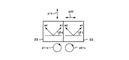
図2及び図3を用いて、位相差部2における入射ビームの偏光方向の変換態様について説明する。一方のビームの偏光方向を、他方のビームの偏光方向と直交する方向に変換させる構成とすることによって、例えば市販の1/2波長板等を位相差部2として用いることができ、コストの低減化、製造工程の簡略化を図ることができる。
The conversion mode of the polarization direction of the incident beam in the
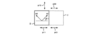
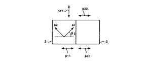
図2においては、1/2波長板を位相差部2として用いる場合で、図1におけるビーム合波素子10の構成図を示し、光源から出射される第1及び第2のビームLi1 及びLi2 のうち、第1のビームLi1 が1/2波長板よりなる位相差部2を介して複屈折材料部1に入射される。このとき、LD等の光源から出射された第1及び第2の入射ビームLi1 及びLi2 の偏光方向は同一方向である。この場合、図2において矢印p11及びp12で示すように図2の紙面に沿う上下方向とする。第1のビームは、1 /2波長板より成る位相差部2の作用により偏光方向がほぼ90度回転するため、複屈折材料部1 内において、矢印p12で示すように図2の紙面に直交する方向の偏光をもって進行する。
FIG. 2 shows a configuration diagram of the
ここで、複屈折材料部1が1軸異方性結晶であるとし、その光軸方向が矢印aで示すように図2の紙面に沿う斜め方向とすると、図2の紙面と直交する偏光方向をもった第1のビームはウォークオフ作用を受けずに複屈折材料部1内を直進する。
一方、図2の紙面に沿う方向に偏光方向をもった第2のビームは、ウォークオフ作用を受けて、エネルギー伝搬方向が変化する。図2において、ρはウォークオフ角を示す。複屈折材料部1の光軸方向aが第2のビームの入射方向に対し例えば45度付近であり、第1及び第2のビームが丁度複屈折材料部1の出射端面において交わる長さにビーム合波素子10の長さを選定すれば、複屈折材料部1から出射される第1及び第2のビームは、同一出射点から同一伝搬方向に出射され、すなわち合波されたビームLoとなる。図2において矢印p13及びp23は合波ビームに含まれる各偏光成分を示す。
Here, assuming that the
On the other hand, the second beam having the polarization direction in the direction along the plane of FIG. 2 undergoes a walk-off action, and the energy propagation direction changes. In FIG. 2, ρ indicates a walk-off angle. The optical axis direction a of the
図3に、位相差部2の、第1及び第2のビームの入射端面からみた平面構成を示す。破線fは、複屈折材料部のビーム入射端面を模式的に示したものである。ここで第1及び第2の入射ビームLi1 及びLi2 の偏光方向が、矢印p11及びp12で示すように、図3の紙面に沿う左右方向であるとし、位相差部2の矢印e1 で示す進相軸と、第1のビームの入射前の偏光方向(矢印p11)とのなす角度θ1 が45度になるように配置すれば、位相差部2から出射後のビームの偏光方向は、矢印p12で示すように、位相差部2の入射前から90度回転する方向に変換されることとなる。位相差部2を通過しない第2のビームの偏光方向は、矢印p22で示すように、入射前と変わらない。
FIG. 3 shows a planar configuration of the
具体的には、例えば複屈折材料部1として、YVO4 を用いて、その光軸が入射ビームの偏光方向と45度を成すときは、入射ビームの波長が800nmから900nmの範囲ではウォークオフ角ρが5.8度、波長1300nm程度ではウォークオフ角ρが5.7度である。図2に示すように、光源からの入射ビームの間隔dが1mmのときに、必要なビーム合波素子の複屈折材料部1の長さlはおおよそ、
l=d/tan(ρ)
=10[mm]
となる。
Specifically, for example, when YVO 4 is used as the
l = d / tan (ρ)
= 10 [mm]
It becomes.
従って、ウォークオフ量が大きいほど必要なビーム合波素子の長さが減少する。もちろん、LD素子の出射ビーム間隔が小さいほど必要なビーム合波素子の長さが減少することは言うまでもない。以下の表1に、代表的な複屈折材料における入射ビームと結晶軸方位との角度に対するウォークオフ量(角度)を示す。各数値は近赤外波長(波長800nm〜900nm)の入射ビームに対するものである。 Therefore, the required length of the beam combining element decreases as the walk-off amount increases. Of course, it goes without saying that the shorter the output beam interval of the LD element, the shorter the required beam combining element length. Table 1 below shows the walk-off amount (angle) with respect to the angle between the incident beam and the crystal axis direction in a typical birefringent material. Each numerical value is for an incident beam at a near infrared wavelength (wavelength 800 nm to 900 nm).

また、この表1に示すYVO4 、KTiOPO4 (KTP)、LiNbO3 (LN)、SiO2 に限定されることなく、その他種々の材料を用いることができる。
例えば、RbTiOPO4 (RTP)、RbTiOAsO4 (RTA)、KTiOAsO4 (KTA)、LiTaO3 (LT)、MgOドープLiNbO3 、MgOドープLiTaO3 、KNbO3 (KN)、BaTiO3 (BTO)、Ba2 NaNb5 O15(BNN)、SrBaNbO7 (SBN)、KH2 PO4 (KDP)、KD2 PO4 (dKDP)、BaB2 O4 (BBO)、LiB3 O5 (LBO)、LiB4 O7 、CsLiB6 O10(CLBO)、CsB3 O5 (CBO)、TiO2 、方解石(Calcite)、MgF2 、CaF2 、α−Al2 O3 、これらの単結晶又は共晶を使用することができる。
Further, without being limited to YVO 4 , KTiOPO 4 (KTP), LiNbO 3 (LN), and SiO 2 shown in Table 1, various other materials can be used.
For example, RbTiOPO 4 (RTP), RbTiOAsO 4 (RTA), KTiOAsO 4 (KTA), LiTaO 3 (LT), MgO-doped LiNbO 3 , MgO-doped LiTaO 3 , KNbO 3 (KN), BaTiO 3 (BTO), Ba 2 NaNb 5 O 15 (BNN), SrBaNbO 7 (SBN),
特に、上述したようにYVO4 、LN、またLT、Al2 O3 、KTPやBBO等はウォークオフ量が大きいことからより複屈折材料部の長さを短くして、小型化を図り易く、またSiO2 は一般的材料であるため取り扱いが簡単で安価である。これらの材料は加工方法が確立されていることから、製造方法が容易となるという利点を有する。 In particular, as described above, YVO 4 , LN, LT, Al 2 O 3 , KTP, BBO, and the like have a large walk-off amount, so that the length of the birefringent material portion is shortened, and it is easy to reduce the size. Since SiO 2 is a general material, it is easy to handle and inexpensive. These materials have an advantage that the manufacturing method is easy because the processing method is established.
また、入射光として用いる光の波長としては、可視光から近赤外の領域、すなわち波長400nm以上1000nm以下程度の波長とすることによって、上述の各材料を用いる場合に、適切な透過率とウォークオフ量を得て、ビーム合波を確実に行うことができる。以下の表2に、可視波長(530nm)における、入射ビームと結晶軸方位との角度に対するウォークオフ量(角度)を示す。 The wavelength of the light used as the incident light is in the range from visible light to the near infrared, that is, a wavelength of 400 nm or more and 1000 nm or less. By obtaining the off amount, beam multiplexing can be performed reliably. Table 2 below shows the walk-off amount (angle) with respect to the angle between the incident beam and the crystal axis direction at the visible wavelength (530 nm).
更に、LDの出射偏光方向が紙面と垂直な場合には、位相差部2に入射した方のビームの伝搬方向を複屈折材料部1内において変換して、その出射端面において両ビームを合波させることもできる。この一例の上面からみた模式的な構成図を図4Aに、側面からみた模式的な構成図を図4Bにそれぞれ示す。図4A及びBにおいて、図1及び図2に対応する部分には同一符号を付して重複説明を省略する。
Further, when the exit polarization direction of the LD is perpendicular to the paper surface, the propagation direction of the beam incident on the
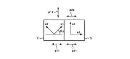
この場合、第1の入射ビームLi1 は位相差部2を通過してその偏光方向が矢印p12で示すように、図4の紙面に沿う方向に変換される。第2の入射ビームLi2 の複屈折材料部1内の偏光方向は矢印p22で示すように、図4Aの紙面と直交する方向とする。複屈折材料部1の結晶軸が、図4Aに示すように、その紙面に沿う斜め方向であり、ウォークオフ作用により、位相差部2を通過した第1のビームのエネルギー伝搬方向が変換される構成とすることができる。
In this case, the first incident beam Li1 passes through the
また、上述の各例において、位相差部2は複屈折材料部1の入射端面にエアーギャップタイプの偏光子のように、複屈折材料部と微小な間隔を持って固定できるような保持材を用いても良いし、透過率と信頼性の高い接着剤で直接接着してもよい。
接着工程としては、位相差部2と複屈折材料部1を別々に加工した後接着しても良いし、先に位相差部2と複屈折材料部1とを接着した後、位相差部2の厚さを研磨等により調整することもできる。後者のプロセスによる場合は材料の強度が確保されるので、例えば位相差部2として、波長板次数の低い、即ち厚さの薄い波長板を用いることによって、波長・温度などの許容範囲を広げることができる。
Further, in each of the above-described examples, the
In the bonding step, the
なお、上述の各例において、位相差部2の材料を複屈折材料部1の材料と同一の材料により構成することによって、位相差部2と複屈折材料部1との界面における屈折率の違いによるビームの反射率を抑制することができて、ビームの利用効率の低下を抑制することができる。
In each of the above-described examples, by forming the material of the
また同様に、位相差部2に入射させるビームに対する位相差部2の屈折率と、このビームに対する複屈折材料部1の屈折率とを同一の材料となるように、各部1及び2を構成することによって、同様に、ビーム反射率を抑制して、ビームの利用効率の低下を抑制することができる。
特に、位相差部2を複屈折材料部1に固定配置する接着剤の材料も、その屈折率が各部1及び2の入射ビームに対する屈折率と同一である材料により構成することによって、よりビーム利用効率の低下を抑制することができる。
Similarly, each of the
In particular, the material of the adhesive that fixes and arranges the
また、位相差部2と複屈折材料部1とのそれぞれの入射端面及び出射端面に適切な反射防止膜を設けることによって、更にビームの反射率を抑制し、より効率よくビームを合波させて、輝度の高い出力光を得ることができる。
位相差部2と複屈折材料部1とを接着剤により接着する場合は、接着剤との界面では接着剤の屈折率を考慮して反射防止膜、いわゆるマッチング膜を設定することが望ましい。
Further, by providing appropriate anti-reflection films on the incident end face and the output end face of each of the
When the
なお、図1及び図2の例においては、複屈折材料部1の結晶の主軸と入射ビームとの成す角度が45度の場合を示したが、この角度は45度に限ることなく、種々の複屈折材料の屈折率特性に応じて最もウォークオフ量が大きくなる方向に結晶光軸を選定することができる。
また、入射ビームの伝搬方向は、完全に平行でなくてもよく、各ビームが多少斜め入射する場合においても、複屈折材料部1 の長さや、結晶軸角度を調整することによって、上述の例と同様に、複屈折材料部1の出射端面において、同様に合波させることができる。
In addition, in the examples of FIGS. 1 and 2, the case is described where the angle formed between the main axis of the crystal of the
Further, the propagation direction of the incident beam may not be completely parallel, and even when each beam is slightly obliquely incident, by adjusting the length of the
このような構成を採ることによって、LD等の光源4からファイバー7までの光路が占有する空間を従来に比し小さくすることができる。
また、位相差部2を保持する支持体いわゆるマウントを別途設ける必要がないことから、例えば光源として近接したLD素子を用いることができる。従って、LDの電極やペルチェ素子等の冷却機構を共通化することができ、各LD素子の出力はそのままで2倍の出力、2倍の輝度を持ち且つ小型の出力光源を実現できることとなる。
By employing such a configuration, the space occupied by the optical path from the
In addition, since it is not necessary to separately provide a support for holding the
更に本発明においては、位相差部と複屈折材料部が一体化されているので取り扱いが容易であり、強度も確保される。また、位相差部の進相軸と複屈折材料部の結晶軸角度などの光学調整は製造過程で行われ、複屈折材料部の長さの調整によって合波位置が決定されるので、各種装置に組み込む際には、利用者が微妙な光学調整を行う必要がなく、励起光出力装置等への組み込みなどの作業性が極めて簡易化される。 Further, in the present invention, since the retardation portion and the birefringent material portion are integrated, handling is easy and strength is secured. In addition, optical adjustment such as the phase axis of the phase difference part and the crystal axis angle of the birefringent material part is performed in the manufacturing process, and the multiplexing position is determined by adjusting the length of the birefringent material part. When the optical head is incorporated into the device, there is no need for the user to make delicate optical adjustments, and workability such as incorporation into an excitation light output device or the like is greatly simplified.
また、上述したように本発明によれば、同一特性のLD光源を用いても2倍の輝度、出力を達成することができるので、特に輝度により効率や特性が大きく変化するような用途に適している。例えば、レーザの励起光源として、特にファイバーアンプレーザのファイバーコアのような微小な領域に、多くのレーザパワーを限られた角度で投入しなければならないような場合に本発明は好適である。 Further, as described above, according to the present invention, even if an LD light source having the same characteristics is used, twice the luminance and output can be achieved, so that the present invention is particularly suitable for applications in which the efficiency and characteristics greatly change depending on the luminance. ing. For example, the present invention is suitable for a case where a large amount of laser power must be applied at a limited angle to a minute area such as a fiber core of a fiber amplifier laser as a laser excitation light source.
また、加工用、医療用、印刷用などの用途においても、本発明により輝度が増加することによって、一定の閾値以上の輝度で現れる加工・治療分野への新たな応用が可能となるとか、またはタクトタイムを短縮することが可能となる。
更に、通信分野においても、光信号の損失を補うために、光増幅の励起光源として用いることができ、励起光源自体の高輝度化によって光増幅部の拡張を行うとか、光増幅モジュール装置の小型化を図るなどの効果を得ることができる。
In addition, for applications such as processing, medical use, and printing, by increasing the luminance according to the present invention, a new application to the processing / treatment field that appears at a luminance equal to or higher than a certain threshold becomes possible, or Takt time can be reduced.
Furthermore, also in the communication field, it can be used as an excitation light source for optical amplification in order to compensate for the loss of an optical signal. Thus, the effect of achieving the effect can be obtained.
なお、図1、図2及び図4に示す例においては、LD素子が並んでいる方向は入射ビームの進行方向に対し横方向としたが、これに限ることなく、例えばLDの活性層に沿う方向と垂直な方向にLD素子が並列配置される構成とすることもできる。この場合、出射されたビームは出射端面近傍では縦にストライプを積み重ねたように並ぶが、同様に本発明によるビーム合波素子を利用してビームの合波を行うことができる。 In the examples shown in FIGS. 1, 2 and 4, the direction in which the LD elements are arranged is transverse to the traveling direction of the incident beam. However, the present invention is not limited to this. It is also possible to adopt a configuration in which LD elements are arranged in parallel in a direction perpendicular to the direction. In this case, the emitted beams are arranged in a vertical stack in the vicinity of the emission end face, but the beams can be combined using the beam combining element according to the present invention.
このようにLD素子を構成する場合は、ストライプ中心を近接させることができるので、複屈折材料部の長さ、即ちビーム合波素子の長さを短くすることができる。また、上述の第1の実施の形態におけるLDの偏光方向は一例を示したものであり、例えば図1の紙面と垂直な偏光方向を持つLDに対しても本発明によるビーム合波素子を構成することができることは前述の通りである。 In the case of configuring the LD element in this manner, the center of the stripe can be made closer, so that the length of the birefringent material portion, that is, the length of the beam combining element can be shortened. Further, the polarization direction of the LD in the above-described first embodiment is an example, and the beam multiplexing device according to the present invention is configured for an LD having a polarization direction perpendicular to the plane of FIG. What can be done is as described above.
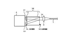
また、上述の例においては光学系5及び6の構成は一例を示したものであり、レンズの種類、光学系の配置などはその他種々の態様を採りうることはいうまでもない。ビーム合波素子出射後のビームは、一旦平行ビームとなる無限レンズ系で構成しても良く、また図5にその一例の模式的な構成を示すように、そのまま集光してファイバーへカップリングする有限系により構成することもできる。図5において、図1と対応する部分には同一符号を付して重複説明を省略する。
Further, in the above-described example, the configuration of the
このように有限の光学系により構成する場合は、レンズ収差などが問題にならず、またLDとファイバーの光軸が予め一致している場合には特に、部品点数や調整の手間の削減に有効である。また、ファイバーへカップリングせずに、図1において説明したコリメートレンズ6の出射後のビームをそのまま各種の装置に利用することもできる。
In the case of using a finite optical system as described above, lens aberration and the like do not become a problem, and particularly when the optical axes of the LD and the fiber are matched in advance, it is effective in reducing the number of parts and the labor for adjustment. It is. Further, the beam emitted from the
このようなビーム合波素子では、一般に波長板等の位相差部の入射角に対する許容幅はPBS(偏光ビームスプリッタ)の入射角許容幅に比べて大きく、また複屈折材料部における入射角許容幅も比較的大きいので、LDからの出射光がコリメートされていなくても十分に合波することができるという利点を有する。 In such a beam multiplexing device, generally, the allowable width of the phase difference portion such as the wavelength plate with respect to the incident angle is larger than the allowable angle of the PBS (polarizing beam splitter), and the allowable angle of the birefringent material portion. Is relatively large, so that there is an advantage that the light emitted from the LD can be sufficiently multiplexed even if it is not collimated.
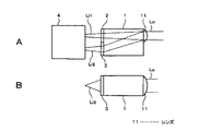
もし、LD出射光の発散角の大きさがビーム合波素子の小型化を阻んだりその結合性能低下の原因となったりするのであれば、例えば図6A及びBにそれぞれ模式的な上面構成及び側面構成を示すように、発散角の大きいほうのビーム、例えば通常LDの共振器長方向と垂直で、活性層と垂直な方向のビーム拡がりを、シリンドリカルレンズ等のレンズ8を用いて適切に抑えてビーム合波素子10に入射させる構成とすることができる。図6A及びBにおいて、図1と対応する部分には同一符号を付して重複説明を省略する。
If the divergence angle of the light emitted from the LD prevents the beam multiplexing element from being miniaturized or causes a reduction in its coupling performance, for example, FIGS. As shown in the configuration, the beam having a larger divergence angle, for example, the beam spread in the direction perpendicular to the cavity length direction of the normal LD and perpendicular to the active layer is appropriately suppressed by using a
以上説明したように、本発明に係る第1の実施の形態によれば、位相差部2を複屈折材料部1に固定配置して構成することによって、ビーム合波素子を簡単な構成をもって作製することが可能となり、且つ、その組み込みにあたって利用者による微妙な光軸調整等を必要とせず、更にはビームの利用効率の低下を抑制することができて、小型で高輝度の出力光が得られるビーム合波素子を提供することができる。
As described above, according to the first embodiment of the present invention, the beam multiplexing device is manufactured with a simple configuration by arranging the
また、位相差部2を1/2波長板により構成することによって、その進相軸と複屈折材料部1の結晶軸とを合わせて固定配置するのみの簡単な製造方法による作製が可能であり、製造工程が簡易で小型、高輝度の出力光源を提供することができる。
In addition, by forming the
〔第2の実施の形態〕
次に、本発明による第2の実施の形態について説明する。
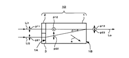
上述の第1の実施の形態においては、ビーム合波素子への入射ビームの片方のみを位相差部に入射させたが、以下の例においては、図7にその一例の模式的な構成を示すように、位相差部2と並置して複屈折材料部1の入射端面1Aに補助位相差部3を設ける場合を示す。図7において、図1と対応する部分には同一符号を付して重複説明を省略する。
[Second embodiment]
Next, a second embodiment according to the present invention will be described.
In the above-described first embodiment, only one of the beams incident on the beam combining element is made to enter the phase difference portion. In the following example, FIG. 7 shows a schematic configuration of one example. Thus, the case where the
この場合においても例えばLD素子が2個並列された光源を用いるもので、この例においては、伝搬方向がほぼ同一で、矢印p11及びp21で示すように、図7の紙面に沿う上下方向の直線偏光とする第1及び第2の入射ビームLi1 及びLi2 が、それぞれ位相差部2及び補助位相差部3を介して複屈折材料部1に入射される構成とする。
Also in this case, for example, a light source in which two LD elements are used in parallel is used. In this example, the propagation direction is almost the same, and as shown by arrows p11 and p21, a straight line in the vertical direction along the paper surface of FIG. First and second incident beams Li1 and Li2 to be polarized are incident on the
ここで補助位相差部3としては、位相差部2とほぼ同じ厚さで、入射ビームの偏光方向に対する屈折率が近い材料による透過板とすることが望ましい。即ち、ビーム合波素子10の入射側にほぼ同じ屈折率をもつ位相差部2と補助位相差部3とを配置し、その厚さをほぼ同一とすることによって、素子10内における2つのビームの光路長をほぼ等しくすることができ、例えばビーム合波素子10への入射ビームが発散角をもっている場合、ビーム合波素子10から出射後のビームの形状、発散角をほぼ抑えることができる。
Here, it is desirable that the
また、これら位相差部2及び補助位相差部3の界面を、各部2及び3の屈折率とほぼ同一の屈折率を有する材料の接着剤等により接着して構成することによって、同じ屈折率を持つ材料の界面は殆ど反射しないので、2つのビーム間にある位相差部2と補助位相差部3との界面での散乱光を抑え、ひいては光源への戻り光を抑えることができる。
In addition, the interface between the
更に、製造工程において、位相差部2と補助位相差部3とを先に複屈折材料部1の入射端面1Aに接着剤等により固定配置してから、その表面を研磨するプロセスを採用すれば、研磨面積を大きく確保できるので、研磨による平行度などのばらつきを抑えることができる。また、位相差部2の端まで光学鏡面を確保できる。更に、補助位相差部3を設けることによって、複屈折材料部1の入射端面1Aを保護することができる。
Further, in the manufacturing process, a process in which the
このような補助位相差部3としては、例えば光学的等方性をもつ材料、例えばBK7、SF11等の光学ガラスを用いることができる。図8に、図7において入射端面側からみた模式的な平面構成を示す。このように光学的等方性を有する材料より補助位相差部3を構成する場合は、補助位相差部3に入射する前の偏光方向(矢印p21)と出射後の偏光方向(矢印p22)は変換されない。
As such an
一方、位相差部2は、前述の第1の実施の形態の一例を示す図2において説明した例と同様に、1/2波長板より構成することによって、入射ビームの偏光方向を90度回転させることができる。図8において、図3と対応する部分には同一符号を付して重複説明を省略する。
On the other hand, the
また、図9にその一例の模式的な平面構成を示すように、補助位相差部3を、位相差部2と同一の複屈折材料より構成し、且つその結晶軸が入射ビームの偏光方向とほぼ同一の向きになるように構成することによって、すなわち例えば補助位相差部3の進相軸が矢印e3 で示すように、入射前のビームの偏光方向(矢印p21)と同一方向となるように構成することによって、偏光方向を保存する透過板として作用させることができる。図9において、図8と対応する部分には同一符号を付して重複説明を省略する。矢印e4 は、補助位相差部3の遅相軸の方向を示す。
Further, as shown in FIG. 9, as an example of a schematic plan configuration, the
この場合は、位相差部2と補助位相差部3とを同一材料とすることによって、これらおよび複屈折材料部1との界面における反射を抑制し、その利用効率の低下を抑えることができる。
また、熱膨張率の差を小さくできるので、加工プロセスや使用方法に関する取り扱いが容易になる。
なお、上述の第2の実施の形態におけるLDの偏光方向は一例を示したものであり、例えば光源の偏光が円偏光の場合も、本発明によるビーム合波素子を構成することができることはいうまでもない。このような偏光方向とする場合には、図7の第1および第2のビームLi1、Li2の通過部分それぞれに円偏光を互いに直交する直線偏光に変換する位相差部2と補助位相差部3を設ければよい。
In this case, by using the same material for the
Further, since the difference in the coefficient of thermal expansion can be reduced, handling regarding the processing process and the method of use is facilitated.
Note that the polarization direction of the LD in the above-described second embodiment is merely an example, and for example, even when the polarization of the light source is circularly polarized, the beam multiplexing device according to the present invention can be configured. Not even. In the case of such a polarization direction, the
〔第3の実施の形態〕
次に、本発明によるビーム合波素子の入射端面、または出射端面にレンズを一体化して設ける場合の実施の形態について説明する。この例においては、前述の第2の実施の形態において説明した、補助位相差部3を位相差部2に並置配列し、その厚さをほぼ同一とし、即ち位相差部2及び補助位相差部3の入射端面を平坦な同一面とする場合に適用した例を示す。
すなわち、図10A及びBにその一例の模式的な平面構成及び側面構成をそれぞれ示すように、位相差部2 及び補助位相差部3の入射端面にレンズ9を設けて、レンズ一体型構成のビーム合波素子を構成する。
[Third Embodiment]
Next, an embodiment in which a lens is integrally provided on the entrance end face or the exit end face of the beam combining element according to the present invention will be described. In this example, the
That is, as shown in FIGS. 10A and 10B, an example of a schematic plan configuration and a side configuration, respectively, a
この場合、レンズ9としてシリンドリカルレンズを用いることにより、LD等からの光の発散角を低減化することができることから、ビーム利用効率の低下を抑制するとともに、ビーム合波素子の小型化を図ることができ、更に、合波後のビームをコリメートし易くすることができる。またこの場合においても、部品点数の削減を図り、また光学調整作業を削減することができ、ビーム合波装置の素子を組み込む装置を更に小型化、装置構成の簡易化が可能となる。
In this case, by using a cylindrical lens as the
更にまた、図11A及びBに、この一例の模式的な平面構成及び側面構成を示すように、複屈折材料部1の出射端面側に同様にレンズ11を設けることもできる。例えばビーム合波素子10においてビームを合波した後、出射端面に取り付けられたコリメータレンズ等のレンズ11によりほぼ平行ビームとして出射させることができる。この場合、コリメータレンズの焦点距離は、光源4を出射したビームが丁度ビーム合波素子10の出射後にコリメートされるような焦点距離に選定する。
Further, as shown in FIGS. 11A and 11B, a schematic plan configuration and a side configuration of this example, a
このようなレンズ9又は11の取り付け方法としては、ビーム合波素子10の複屈折材料部1に対し光学的にほぼ透明な接着剤などで接着されることが望ましい。また、複屈折材料部1と接着剤、接着剤とレンズ9又は11の間、更にレンズ9又は11の表面には、適切な反射防止膜を被着することが望ましい。このような反射防止膜を設けることによって、LD等の光源への戻り光を防ぐと共に、レンズを取り付けたビーム合波素子でのレーザパワー損失を低く抑えることができる。
As a method for attaching such a
なお、図11に示すように、レンズ11の曲面部がコリメート光側に向いている場合は、レンズの収差を小さく抑えることができる。レンズの形状を非球面形状とする場合は更に収差を小さく抑えることができる。従って、より効率よくビームを合波させることができる。
Note that, as shown in FIG. 11, when the curved surface of the
更に、入射端面と出射端面ともにレンズ9及び11を設けることもでき、この場合は更にビーム利用効率の向上をはかり、またビーム合波素子を組み込む装置の小型化、光学調整の簡易化による製造方法の簡易化、したがって生産性の向上を図ることができることとなる。
Further,
またこのように光学系が一体化されたビーム合波素子を構成することによって、超小型の高輝度励起光発生装置を提供することができる。
更にまた、適切な外形精度をもったレンズ付きビーム合波素子を、各部品の外形精度を確保することによって組み立て構成する場合は、更に光学調整の作業を省略し、機械的安定性を確保することができることとなる。各部品の光学的調整方法としては、例えばHe−Neレーザなどの平行ビームで光軸を合わせることにより、ビーム合波素子を比較的簡単な作業で所定の外形精度をもって接着、組み立てを行うことができる。
Further, by configuring the beam multiplexing device in which the optical system is integrated as described above, it is possible to provide an ultra-compact high-brightness excitation light generator.
Furthermore, when assembling and configuring a beam combining element with a lens having an appropriate outer shape accuracy by ensuring the outer shape accuracy of each component, the work of optical adjustment is further omitted and mechanical stability is ensured. You can do it. As an optical adjustment method of each component, for example, by aligning the optical axis with a parallel beam such as a He-Ne laser, the beam multiplexing element can be bonded and assembled with a predetermined outer shape accuracy by a relatively simple operation. it can.
なお、上述の実施の形態におけるビーム合波素子とレンズの組み合わせ及びその作用は、上述の例に限定されることなく、レンズの種類や取り付け方法など種々の変形、変更が可能である。例えば、複屈折材料部1の表面を変形させることによって、レンズ作用をもたせることも可能である。レンズ形状は、収差が小さい場合には例えば球面状とすることもできる。また、複屈折材料部1の出射端面に取り付けるレンズを集光レンズとし、直接ファイバーへ結合させることもできる。
レンズに用いる材料としては、前述の複屈折材料部の材料として示した各材料を用いることができる。またBK7、SF11等の光学ガラスも容易に用いることができる。
The combination of the beam multiplexing element and the lens in the above-described embodiment and the operation thereof are not limited to the above-described example, and various modifications and changes such as the type of lens and the mounting method can be made. For example, by deforming the surface of the
As the material used for the lens, each material shown as the material of the above-described birefringent material portion can be used. Further, optical glass such as BK7 and SF11 can be easily used.
〔第4の実施の形態〕
次に、位相差部及び補助位相差部を各種の位相差板、いわゆる波長板を組み合わせて構成した場合の実施の形態の各例について説明する。
上述の各実施の形態の各例においては、位相差部として1/2波長板を用いた例を示したが、この例においては、1/4波長板を組み合わせて構成する場合を示す。
[Fourth Embodiment]
Next, each example of an embodiment in which the phase difference portion and the auxiliary phase difference portion are configured by combining various phase difference plates, so-called wavelength plates, will be described.
In each of the above-described embodiments, an example in which a 波長 wavelength plate is used as a phase difference unit has been described. In this example, a case in which a 波長 wavelength plate is combined is shown.
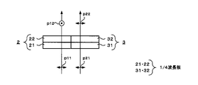
図12は、位相差部2及び補助位相差部3をそれぞれ2枚の1/4波長板により構成する場合の位相差部2及び補助位相差部3の上面からみた模式的な構成を示す図で、位相差部2を1/4波長板21及び22、補助位相差部3を1/4波長板31及び32より構成する。入射ビームのうち、位相差部2を通過するビームは、偏光方向が入射前は矢印p11で示すように図12の紙面に沿う横方向であるとすると、位相差部2を通過後に矢印p12で示すように図12の紙面と直交する方向に、90度回転する構成とし、一方補助位相差部3においては、その通過前後において、入射ビームの偏光方向が、矢印p21及びp22で示すように変換されない構成とする。
FIG. 12 is a diagram illustrating a schematic configuration of the
具体的には、例えば図13にビームの入射方向からみた模式的平面構成を示すように、入射端面側(即ち光源側)の位相差部の1/4波長板21の進相軸の向きは、矢印e1で示すように、矢印p11で示す入射ビームの偏光方向と角度θ4 が45度を成すようにし、補助位相差部の1/4波長板31の進相軸の向きは、矢印e5 で示すように、矢印p21で示す入射ビームの偏光方向との角度θ5 が、θ4 とは逆向きに45度を成し、それぞれの進相軸が90度を成すように配置構成を選定する。この場合、各1/4波長板21及び31を通過した入射ビームは、それぞれ矢印p11a 及びp21a で示すように右向き及び左向きの円偏光に変換される。
More specifically, for example, as shown in FIG. 13, which shows a schematic plan configuration viewed from the incident direction of the beam, the direction of the fast axis of the 波長
そして、複屈折材料部側の位相差部及び補助位相差部の1/4波長板22及び32の進相軸の向きを、図14にビームの入射方向からみた模式的平面構成を示すように、矢印e1で示すように、1/4波長板21と同様に、位相差部2及び補助位相差部3に入射する前の入射ビームの偏光方向との角度θ6 及びθ7 が45度を成すように選定することによって、矢印p11a 及びp21a で示すように円偏光として入射された各ビームを、矢印p12及びp22で示すように、互いに直交する方向に偏光方向を有する直線偏光のビームにそれぞれ変換することができる。この例においては、位相差部2を通過した入射ビームの偏光方向が90度変換される構成とした場合である。
The direction of the fast axes of the
このような位相差板の組み合わせを用いることによって、具体的には、同一の1/4波長板のうち1枚の貼り付け方向を変えるだけで、上述の第2の実施の形態と同じ作用をもつ位相差部及び補助位相差部を構成することができる。
ここで、各1/4波長板21及び22、また31及び32はそれぞれ入射ビームの伝搬方向に対し逆の順番に配置されていても同様の偏光方向の変換作用を得ることができる。また、1/4波長板22及び32の代わりに、1枚のいわば横長の1/4波長板を設けてもよく、また位相差部2を1枚の1/2波長板を用いて構成することもできるなど、その他種々の変形、変更が可能であることはいうまでもない。
By using such a combination of retardation plates, specifically, the same operation as that of the above-described second embodiment can be achieved only by changing the attaching direction of one of the same quarter-wave plates. The phase difference part and the auxiliary phase difference part can be configured.
Here, even if the quarter-
更にまた、1/2波長板として、厚さの異なる波長板を、その波長板としての進相軸と遅相軸とが直交するように2枚貼り合わせて、2つの固有偏光間の屈折率差Δn及び厚みの差Δtが、
Δn・Δt=(k+1/2)λ
(kは0以上の整数)
となるように、各波長板を構成することによって1/2波長板を構成して、即ち偏光方向が90度変換されるように位相差板を貼り合わせたものを用いることもできる。
Furthermore, as a half-wave plate, two wave plates having different thicknesses are attached to each other so that the fast axis and the slow axis of the wave plate are orthogonal to each other, and the refractive index between the two intrinsic polarizations is set. The difference Δn and the thickness difference Δt are
Δn · Δt = (k + /) λ
(K is an integer of 0 or more)
Thus, a half-wave plate can be formed by forming each wave plate, that is, a wave plate obtained by bonding a retardation plate so that the polarization direction is converted by 90 degrees can be used.
すなわち、上述の各例に限定されることなく、入射前後で位相差部または補助位相差部の一方においてのみ90度変換され、他方において、偏光方向が変換されない構成とすることによって、前述の第1及び第2の実施の形態と同様の効果を得ることができる。 That is, without being limited to each of the above-described examples, the 90-degree conversion is performed only in one of the phase difference portion and the auxiliary phase difference portion before and after the incidence, and the polarization direction is not changed in the other. The same effects as those of the first and second embodiments can be obtained.
なお、偏光方向の変換が90度以外の方向である場合においても、複屈折材料部の結晶軸との配置構成を考慮することによって2つの入射ビームのうち一方のみがウォークオフ作用を受けて伝搬方向が変換されるように構成することによって、本発明によるビーム合波を行うことが可能である。
しかしながら、上述したように、偏光方向を90度変換させる構成とする場合においては、入射ビームの偏光方向と、複屈折材料部の結晶軸との方向を位置合わせするのみで比較的簡単にビーム合波素子を構成することができるという利点を有する。
Even when the polarization direction is changed to a direction other than 90 degrees, only one of the two incident beams undergoes the walk-off effect and propagates by taking into account the arrangement of the birefringent material with the crystal axis. By arranging the directions to be changed, it is possible to perform beam multiplexing according to the present invention.
However, as described above, in a case where the polarization direction is changed by 90 degrees, the beam alignment can be relatively easily performed only by aligning the polarization direction of the incident beam with the crystal axis of the birefringent material portion. There is an advantage that a wave element can be configured.
〔第5の実施の形態〕
上述の各実施の形態においては、複屈折材料部として直方体形状の複屈折素子を用いてビーム合波素子を構成した例を示したが、以下の例においては、光学軸方向が直交する直角プリズム2個を組み合わせたウォラストン・プリズムを応用させ、2個の複屈折素子を貼り合わせて複屈折材料部を構成したいわば変形ウォラストン型構成とした例を示す。
[Fifth Embodiment]
In each of the above-described embodiments, an example has been described in which the beam combining element is configured using a rectangular parallelepiped birefringent element as the birefringent material portion. An example of a modified Wollaston type configuration in which a birefringent material portion is formed by bonding two birefringent elements by applying a Wollaston prism in which two are combined is shown.
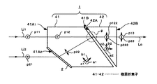
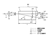
この場合、図15にその一例の模式的な構成図を示すように、複屈折材料部はビーム入射側の複屈折素子41と出射側の複屈折素子42とより構成される。そして入射側の複屈折素子41の入射端面側に一部傾斜面が設けられ、第1のビームLi1 はその伝搬方向と直交する入射端面41A1 に入射され、第2のビームLi2 は一定の入射角度をもって入射端面41A2 に入射されて、各ビームLi1及びLi2 が異なる角度をもって入射されるように構成する。第2のビームLi2 の入射端面41A2 には、例えば位相遅延膜を被着して位相差部2を構成することができる。
In this case, the birefringent material portion is composed of a
一方複屈折素子41の出射端面41Bも斜めの傾斜面とされ、この傾斜面と対向して、他方の複屈折素子42の入射端面42Aが固定配置される。複屈折素子42の出射端面42Bは、出射ビームの伝搬方向と直交する平面として構成される。
On the other hand, the outgoing end face 41B of the
このような構成における各入射ビームLi1 及びLi2 の偏光方向の変換態様について説明する。
各入射ビームの偏光方向が、例えば矢印p11及びp12で示すように、図15の紙面と垂直な方向であり、各複屈折素子41及び42の結晶軸方向が、それぞれ矢印a1 、b1 及びc1 、またa2 、b2 及びc2 で示すように、例えば一の結晶軸方向a1 及びa2 が同一方向であり、共に図15の紙面に垂直な方向であるとする。
The manner of converting the polarization directions of the incident beams Li1 and Li2 in such a configuration will be described.
The polarization direction of each incident beam is, for example, as shown by arrows p11 and p12, which is perpendicular to the plane of FIG. 15, and the crystal axis directions of the
ここで、第1の入射ビームLi1 は複屈折素子41の入射端面41A1 に垂直に入射する。この時、結晶軸に沿う偏光成分なのでそのまま偏光方向は矢印p12で示すように変換されずに、複屈折素子41内を直進する。
もう一方のビームLi2 は、位相差部2に斜めに入射し、この位相差部2の作用により、偏光方向は矢印p22で示すように、図15の紙面に沿う斜め方向に変換される。そして2つのビームがウォークオフ作用により所定の位置に集まるように複屈折素子41より出射され、複屈折素子42に入射する。
Here, the first incident beam Li1 is perpendicularly incident on the incident end face 41A1 of the
The other beam Li2 is obliquely incident on the
このとき、上述したように複屈折素子41及び42が共に図15の紙面と垂直な方向に同じ結晶軸を持つように構成する。このように構成すると、複屈折素子41及び42の内部では、図15の紙面に垂直な方向の偏光をもつビームの感じる屈折率は等しいので、第1のビームは、複屈折素子42内においても、再び同一の方向に直進して伝搬する。矢印p122 及びp222 はそれぞれ各ビームの複屈折素子42内での偏光方向を示す。
At this time, as described above, the
一方、複屈折素子41及び42の界面の角度は、図15の紙面内に沿う偏光方向をもって複屈折素子41を出射する第2のビームが、複屈折素子42内において、第1のビームと合波して伝搬するように決定する。
On the other hand, the angle of the interface between the
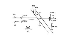
例えば、図15において破線gで囲むビーム合波位置を図16に拡大して示すように、第1及び第2の複屈折素子41及び42の各端面41B及び42Aの角度、間隔、更に複屈折素子41及び42の屈折率等を適切に選定することによって、第1の複屈折素子41の出射端面41Bから、ビームLi1 ’及びLi2 ’がそれぞれ異なる角度で出射され、第2の複屈折素子42の入射端面42Aにおいて合波され第2の複屈折素子から出射ビームLoとして出射されるようにすることができる。
For example, as shown in FIG. 15, the beam multiplexing position surrounded by a broken line g in FIG. 15 is enlarged and shown in FIG. 16, the angles, intervals, and further birefringence of the end faces 41B and 42A of the first and second
または、図17に同様にビーム合波位置を拡大して示すように、第1の複屈折素子41の出射端面41Bにおいて、各ビームを合波させ、第1の複屈折素子41から一つのビームLi3 として出射させて第2の複屈折素子42に入射させ、ここから出射ビームLoとして出射させることもできる。この場合は複屈折素子42の代わりに光学ガラスなどの等方媒質を用いることもできる。図16及び図17において、図15と対応する部分には同一符号を付して重複説明を省略する。
Alternatively, as shown in an enlarged manner in FIG. 17, the beam multiplexing position is such that the beams are multiplexed at the exit end face 41B of the first
このような変形ウォラストン型構成の複屈折材料部を構成する場合は、上述したように、複屈折材料部を構成する各複屈折素子の屈折率、結晶軸の角度のほか、図18に模式的に示すように、例えば複屈折素子41の上面から第1のビームの入射点までの距離d1 、第1及び第2のビームLi1 及びLi2 の入射前の間隔d2 、複屈折素子41の上面から位相差部2の上端までの間隔d3、位相差部へ入射される方のビーム、この場合第2のビームの位相差部2への入射角度θ11、また各複屈折素子の形状としては、例えば第1の入射ビームの伝搬方向に沿う上面の各複屈折素子41及び42の長さl1 及びl2 、またこの上面と、各複屈折素子が対向する傾斜面(すなわち複屈折素子41の出射端面41Bと複屈折素子42の入射端面42A)との成す角度θ12及びθ13、複屈折素子41及び42の間隔l3 などを適切に選定することによって、前述の第1〜第3の実施の形態と同様に、ほぼ同一方向に偏光方向を有する第1及び第2のビームを同一位置において合波させ、同一方向に伝搬して出射させるようにすることができる。
When the birefringent material portion having such a modified Wollaston type configuration is formed, as described above, in addition to the refractive index and the crystal axis angle of each birefringent element forming the birefringent material portion, FIG. As shown in the figure, for example, the distance d1 from the upper surface of the
〔第6の実施の形態〕
前述の各例においては、2つのLD等の光源からのビームを合波させる例を示したが、本実施の形態においては、例えばアレイレーザのように多数のビームを出射する光源からのビームのうち2本ずつを合波させる例について説明する。
図19において、1はKTP等より成る複屈折素子で、その入射端面に1/2波長板等より成る位相差部2と光学的等方性を有する透過板等より成る補助位相差部3とが、ほぼ同一の厚さをもって固定配置されて成る。
そして位相差部2及び補助位相差部3に、それぞれn個(nは1以上の整数)ずつの第1群及び第2群のビームLi11〜Li1n、Li21〜Li2nが入射される。
[Sixth Embodiment]
In each of the above-described examples, an example in which beams from two light sources such as LDs are combined has been described. In the present embodiment, for example, a beam from a light source that emits a large number of beams such as an array laser is used. An example in which two of them are combined will be described.
In FIG. 19,
Then, n (n is an integer of 1 or more) first group and second group beams Li11 to Li1n and Li21 to Li2n of n (n is an integer of 1 or more) are incident on the
この場合においても、前述の第2の実施の形態において説明した図7等の例と同様に、各ビームの偏光方向、複屈折材料部1のビーム伝搬方向の長さ、結晶軸方向を選定することによって、各群のビームは、それぞれ複屈折材料部1の出射端面において合波され、即ち2nのビーム群をn個の出射ビームLo1 〜Lon に合波することができる。
Also in this case, the polarization direction of each beam, the length of the
このように構成することによって、アレイLD等のビーム数を半分にし、輝度をそれぞれ2倍にすることができ、アレイビームを集光し易くすることができる。 With this configuration, the number of beams of the array LD and the like can be halved, the luminance can be doubled, and the array beams can be easily focused.
更に、図20にその一例の構成を示すように、図19において説明したビーム合波素子を2つ用意し、その出射ビーム位置を近接させて組み合わせることによって、例えば2(n+m)個(mは1以上の整数)の入射ビームLi11〜Li1n、Li21〜Li2n、Li31〜Li3m、Li41〜Li4mを、(n+m)個の出射ビームLo1 〜Lon+m に合波させることができる。
なお、図19の例と比較して図20に示す構成とする場合は、ウォークオフ量を小さくすることができる。例えば、m=nである場合、図20に示す例においては、必要なウォークオフ量が半減することから、複屈折材料部1の長さを図19の構成例と比較して1/2とすることができる。従って、複屈折材料部1の長さを短くすることが出来て、小型化に有利となる。
Further, as shown in FIG. 20, an example of the structure is prepared by preparing two beam multiplexing elements described in FIG. 19 and combining the output beam positions close to each other, for example, 2 (n + m) pieces (m is (An integer of 1 or more) incident beams Li11 to Li1n, Li21 to Li2n, Li31 to Li3m, and Li41 to Li4m can be combined into (n + m) outgoing beams Lo1 to Lon + m.
In the case of the configuration shown in FIG. 20 as compared with the example of FIG. 19, the walk-off amount can be reduced. For example, when m = n, in the example shown in FIG. 20, since the necessary walk-off amount is reduced by half, the length of the
〔第7の実施の形態〕
本発明によるビーム合波素子を用いると、近接したビームであれば、その横ずれを補正して同一ビームに重ね合わせることができる。
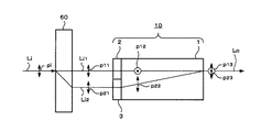
図21に、色収差の大きな光学素子60のビーム横ずれを補正するビーム合波素子10の作用を説明する。図21において、図7と対応する部分には同一符号を付して重複説明を省略する。
[Seventh Embodiment]
By using the beam multiplexing device according to the present invention, if the beams are close to each other, the lateral shift can be corrected and the beams can be superimposed on the same beam.
FIG. 21 illustrates the operation of the
入射ビームLiが異なった波長成分を持つとき、特にその波長差が大きい場合には、波長による色収差の影響で光学素子60出射後のビームはビームの横ずれを起こすことがある。この横ずれ量が大きく出射ビームがLi1及びLi2で示すように分かれるような場合は、横ずれ量に合わせて複屈折材料部の長さを調整したビーム合波素子10を、図21に示すように、光学素子60の後段に配置して、再び一つのビームLoに合波することができる。例えば波長差が大きいため横ずれ量が大きな場合には、非常に有効である。
When the incident beam Li has a different wavelength component, particularly when the wavelength difference is large, the beam emitted from the
矢印p11で示す一方のビームLi1 の偏光方向が、ビーム合波素子10の入射側の波長板等の位相差部2で90度変換される構成とすることによって、ビーム合波素子出射後のビームは互いに直交する偏光方向p12及びp13をもつビームとなる。しかし、例えば特定波長のビームに対して1/2波長板として作用し他の波長のビームに対しては波長板作用を示さない構成の位相差部を設計し、この位相差部をビーム合波素子の後段に配置することにより、2つのビームを同一偏光方向に戻すこともできる。同様な位相差部をビーム合波素子の入射端の位相差部2、3に代えて取り付ければ、ビーム径に比べビーム横ずれが小さく重なり合っているビームでも横ずれ補正を行うことができる。このような波長板は、高い次数の波長板や異なる材料の貼りあわせによる波長板等により実現することができる。
The configuration is such that the polarization direction of one beam Li1 indicated by arrow p11 is converted by 90 degrees by the
〔第8の実施の形態〕
次に、図22を用いて波長変換によるウォークオフの補正を行うビーム合波素子の動作態様について説明する。図22において、図21と対応する部分には同一符号を付して重複説明を省略する。簡単のため波長変換がタイプ1(即ち入射偏光が常光線のみ)の第2次高調波発生である場合とする。偏光方向が矢印pi で示すように、図22の紙面に垂直な方向とされた入射ビームLiを波長変換素子70に入射すると、基本光は直進して第1のビームLi1 として出射され、波長が1/2に変換される変換光は、ある角度をもって伝搬方向が傾斜したのち、基本光の出射ビームである第1のビームLi1 と一定の間隔をもって平行に出射される。これを第2のビームLi2 とする。例えば入射光の波長を1064nmとすると、第1のビームLi1 の波長は入射ビームLiと等しく、変換光である第2のビームLi2 の波長は、基本光の半分、すなわち例えば波長532nmの光となる。
[Eighth Embodiment]
Next, an operation mode of the beam multiplexing element that performs walk-off correction by wavelength conversion will be described with reference to FIG. 22, parts corresponding to those in FIG. 21 are denoted by the same reference numerals, and redundant description will be omitted. For simplicity, it is assumed that the wavelength conversion is the generation of the second harmonic of type 1 (that is, the incident polarization is only ordinary light). As shown by an arrow pi, when the incident beam Li whose direction of polarization is perpendicular to the plane of the paper of FIG. 22 is incident on the
第2のビームLi2 の偏光方向は異常光線で、その偏光方向は入射基本光の矢印p11で示す偏光方向と直交する偏光方向(矢印p21)のビームとなり、また、この第2のビームLi2 はウォークオフ作用を受けて出射ビームの形状は横長のビーム形状となる。高効率な波長変換素子70では、変換されるにつれその分基本光が減衰し、ビームの進行方向に対して急激に変換効率が落ちるので、出射ビームのエネルギー成分は残留基本光と離れた方向に集中する。このような場合、波長変換後の基本光と変換光、即ちビームLi1 及びLi2 に対して図22に示すようにビーム合波素子10を配置することによって、ウォークオフ作用を利用して1つのビームに合波することができる。
The polarization direction of the second beam Li2 is an extraordinary ray, and the polarization direction is a beam having a polarization direction (arrow p21) orthogonal to the polarization direction indicated by the arrow p11 of the incident basic light, and the second beam Li2 is a walk beam. Due to the OFF action, the shape of the output beam becomes a horizontally long beam shape. In the high-efficiency
この場合、ビーム合波素子10へ入射する基本光と変換光の偏光方向は異なる。基本光の偏光方向は、この基本光が入射する端面に波長板を設けるなどにより、変換光の偏光方向と同一方向に変換することができる。この場合、図22に示すように矢印p21及びp22で示す各ビームの偏光方向と、複屈折材料部1の結晶軸方向が共に図22の紙面に沿う方向とすると、両ビームともウォークオフ作用を受けることとなる。しかしながら、両ビームの波長が異なることから、波長が例えばほぼ1/2である変換光がLi1とLi2の間隔に対応した、基本光に対するより大きなウォークオフ量をもつように、各材料及び波長を選定することによって、複屈折材料部1の出射端面においてこれら基本光及び変換光を合波させ、且つ同一方向に伝搬する1のビームとして出射させることができることとなる。
In this case, the polarization directions of the fundamental light and the converted light incident on the
また、このビーム合波後の出射光を用いることによって、タイプ1の和周波即ち第3高調波発生を行うと、ビームが重なっているので効率的に変換を行うことができる。各波長変換素子前後には、適切なレンズを配置するのが好適であることはいうまでもない。また、波長変換素子70の長さは、出射後のビームが分かれる程度にあえて大きくとることもできる。位相差部を設けずに、基本光と変換光とで直交する偏光で複屈折材料部1に入射させる場合、出射後のビームを用いて和周波発生を行う場合はタイプ2(入射光に常光線と異常光線を含む)となる。
Further, when the sum frequency of the
一方、本発明によるビーム合波素子を用いることによって、この場合出射後に基本光に対してのみ1/2波長板として作用する位相差部を配置して、後段の波長変換(和周波発生)などの前にビーム偏光方向を等しくすることができることとなり、タイプ1の和周波混合を行うことが可能となる。
On the other hand, by using the beam multiplexing element according to the present invention, in this case, a phase difference portion that acts as a half-wave plate only for the basic light after emission is disposed, and wavelength conversion (sum frequency generation) at the subsequent stage is performed. , The beam polarization directions can be equalized, and
このように、本発明によるビーム合波素子を用いることによって、波長や偏光によるビームの横ずれを補正して1つのビームに合波しビームプロファイルを改善することができて、ビームの取り扱いを簡単化し、波長変換装置の装置構成の簡易化、ひいては小型化及び高効率化を図ることができることとなる。 As described above, by using the beam multiplexing element according to the present invention, it is possible to correct the lateral shift of the beam due to the wavelength and the polarization, multiplex the beam into one beam and improve the beam profile, and to simplify the handling of the beam. Therefore, it is possible to simplify the device configuration of the wavelength conversion device, thereby achieving downsizing and high efficiency.
〔第9の実施の形態〕
次に、本発明によるビーム分離素子の一実施の形態についてその一例の構成を示す図23を参照して説明する。
本発明のビーム分離素子20は、複屈折材料部1と、その出射端面の一部に位相差部2とを固定配置した構成とされる。矢印aは複屈折材料部1の結晶光軸を示す。図23において、12は例えばコリメートレンズで、矢印p31及びp41で示す偏光成分をもつ入射光Liが複屈折材料部1に入射されると、複屈折作用によりビームは常光線と異常光線とに分離される。このとき各ビームの偏光方向は、紙面に垂直な方向p32と、これとは直交し、例えば紙面に沿う上下方向p42との2方向に変換される。
一方のビームを、位相差部2に通過させて偏光方向を変換することによって、同一の偏光方向p33及びp43をもつ2つのビームLo1 及びLo2 に分離することができることとなる。なお、コリメートレンズなどのレンズは、入射光の特性により、またその他必要に応じて配置すればよいことはいうまでもない。
[Ninth embodiment]
Next, an embodiment of a beam separating element according to the present invention will be described with reference to FIG.
The
By passing one beam through the
このような分離素子を用いて、また前述の合波素子と組み合わせることにより、光通信分野において用いられる各種の分波・合波装置、波長ルーター、偏波無依存光アイソレーター等に用いることができる。
例えば前述の合波素子を用いることにより、光通信分野において、同じ偏光をもつ2つのビームの信号光を、互いに直交する偏光方向を有する信号光の1つのビームに合波することができる。入射ビームの波長やその他の特性は異なっていても構わない。波長が異なる場合、位相差部及び複屈折材料部をそれぞれのビームの波長に合わせて設計すればよい。
By using such a separating element and combining with the above-mentioned multiplexing element, it can be used for various demultiplexing / multiplexing apparatuses, wavelength routers, polarization-independent optical isolators and the like used in the optical communication field. .
For example, by using the above-described multiplexing element, in the optical communication field, two beams of signal light having the same polarization can be multiplexed into one beam of signal light having polarization directions orthogonal to each other. The wavelength and other characteristics of the incident beam may be different. When the wavelengths are different, the phase difference portion and the birefringent material portion may be designed according to the wavelength of each beam.
また、図23に示すビーム分離素子を用いることにより、例えば偏光によって信号光を分波することもできる。この場合も、図23に示すように、前述の各実施の形態におけるビーム伝搬方向・入出射端面を逆に構成すればよい。このような分波・合波素子を順に並べ、かつ分波素子と合波素子との間に所望の目的を持つ光学素子を配置することによって、信号光の特性を片側のビームだけ、あるいは両ビームとも特性を変換することもできる。 Further, by using the beam separation element shown in FIG. 23, for example, the signal light can be split by polarization. Also in this case, as shown in FIG. 23, the beam propagation direction and the input / output end face in each of the above-described embodiments may be reversed. By arranging such demultiplexing / multiplexing elements in order and by arranging an optical element having a desired purpose between the demultiplexing element and the multiplexing element, the characteristics of the signal light can be changed to only one side of the beam or to both sides. Both the beam and the characteristics can be converted.
ここでいう光学素子とは、例えば波長フィルターやアイソレーター、光変調器などである。例えば電気光学効果や音響光学効果を用いた光変調器のような信号入力により能動的に光学的な変換を行う光学素子を用いて、光スイッチを構成することもできる。 The optical element referred to here is, for example, a wavelength filter, an isolator, an optical modulator, or the like. For example, an optical switch can be configured using an optical element such as an optical modulator using an electro-optic effect or an acousto-optic effect, which actively performs optical conversion by signal input.
また更に、アイソレーターのように偏光に依存する特性を持つ光学素子であっても、分波素子を用いることにより、同一偏光の2つのビームに分波することができ、偏光方向に依存する光学素子を適切に配置し、後段においてビーム合波素子によって再び1つのビームに合波すれば、偏波無依存型光学素子として作用させることができることとなる。
更に、1ビームではなく複数のビーム群を入射する場合には、2倍の数のビーム群に分離することもでき、各種分波装置等に用いて装置構成の簡易化、小型化を図ることも可能である。
Furthermore, even if the optical element has a polarization-dependent characteristic such as an isolator, the use of the demultiplexing element can separate the light into two beams of the same polarization, and the optical element depends on the polarization direction. Is appropriately arranged, and is combined again into one beam by the beam combining element in the subsequent stage, so that it can function as a polarization independent optical element.
Further, when a plurality of beam groups are incident instead of one beam, the beam groups can be separated into twice as many beam groups, and the configuration of the apparatus can be simplified and downsized by using the apparatus for various demultiplexers. Is also possible.
以上説明したどの例においても、本発明によるビーム合波素子・分波素子を用いることによって、位相差部と複屈折材料部とが一体化していることから、アライメントが容易で小型化が可能な光学装置を低コストで作製することができるという利点を有する。 In any of the examples described above, by using the beam multiplexing element / demultiplexing element according to the present invention, the phase difference portion and the birefringent material portion are integrated, so that alignment is easy and miniaturization is possible. There is an advantage that the optical device can be manufactured at low cost.
このように、本発明によれば、ビーム合波素子又はビーム分離素子において、位相差部と複屈折材料部とが一体化していることから、光学部品の調整機構の削減や調整作業を省くことができ、強度や取り扱い安さの向上を図り、生産性の向上、部品点数の削減によるコストの低減化、信頼性の向上を図ることができる。 As described above, according to the present invention, since the phase difference portion and the birefringent material portion are integrated in the beam multiplexing device or the beam splitting device, reduction of the adjustment mechanism of the optical component and the adjustment work can be omitted. Thus, strength and ease of handling can be improved, productivity can be improved, cost can be reduced by reducing the number of parts, and reliability can be improved.
また、本発明によるビーム合波素子によれば、入射角に対する許容範囲を従来に比し拡大することができることから、完全なコリメートビームでなくても比較的高い合波効率をもって合波させることができる。また、合波のための精密な光学調整を不要とすることができる。 Further, according to the beam multiplexing device of the present invention, since the allowable range for the incident angle can be expanded as compared with the related art, it is possible to multiplex with a relatively high multiplexing efficiency even if the beam is not a perfect collimated beam. it can. Also, precise optical adjustment for multiplexing can be eliminated.
このような本発明によるビーム合波素子を利用した励起光出力装置によれば、小型で高輝度の光源を提供することによって、効率の良いレーザを実現することができる。
特にファイバーアンプレーザまたはファイバーレーザの励起光源として適用することによって、より小型で高輝度のファイバーアンプレーザまたはファイバーレーザを提供することができる。また、光通信における光増幅に励起光源としても用いる場合には、小型化の他、増幅間隔を広げる効果を得ることもできる。
According to such an excitation light output device using a beam combining element according to the present invention, an efficient laser can be realized by providing a small and high-luminance light source.
In particular, by applying the present invention as a fiber amplifier laser or an excitation light source for a fiber laser, a fiber amplifier laser or a fiber laser with smaller size and higher luminance can be provided. In addition, when used as an excitation light source for optical amplification in optical communication, it is possible to obtain an effect of increasing the amplification interval in addition to reducing the size.
また、光通信などにおけるビーム合波装置として用いることも可能であり、種々のビーム合波素子を利用した光通信装置において、ビーム合波装置の小型化、強度や取り扱い安さの点での信頼性の向上を図ることができる。
その他レーザ加工、医療用、印刷装置などに本発明によるビーム合波素子及びビーム合波方法を用いることによって、同様に、装置の小型化、コストの低減化を図ることができる。
It can also be used as a beam multiplexing device in optical communications, etc., and in an optical communication device using various beam multiplexing elements, the reliability of the beam multiplexing device in terms of miniaturization, strength, and ease of handling is reduced. Can be improved.
In addition, by using the beam multiplexing device and the beam multiplexing method according to the present invention for laser processing, medical use, a printing device, and the like, the size and cost of the device can be similarly reduced.
更に、異なる波長の光を合波することもできるので、色収差の大きな光学素子において、そのビーム横ずれを補正することができる。
また、多段階波長変換装置、すなわち2次高調波光を利用した第3高調波発生装置、第4高調波発生装置に本発明によるビーム合波素子及びビーム合波方法を適用することによって、変換光のウォークオフ分を補正して基本波と同一光軸に簡単に合波することができ、位相差板と各光学系との配置調整などの手間を不要とし、和周波発生などにおける波長変換の高効率化、ビームプロファイルの改善、および装置の小型化を図ることができる。
Further, since lights of different wavelengths can be multiplexed, the lateral displacement of the beam can be corrected in an optical element having a large chromatic aberration.
Further, by applying the beam multiplexing device and the beam multiplexing method according to the present invention to a multi-stage wavelength conversion device, that is, a third harmonic generation device and a fourth harmonic generation device using the second harmonic light, the converted light can be obtained. Can be easily multiplexed on the same optical axis as the fundamental wave, eliminating the need for adjusting the arrangement of the phase difference plate and each optical system, and reducing the wavelength conversion for sum frequency generation. High efficiency, improved beam profile, and downsizing of the apparatus can be achieved.
また更に本発明によるビーム分離素子及びビーム分離方法によれば、任意の偏光を持つ光信号を、同一偏光の光信号に分波することができるので、光通信などにおけるあらゆるビーム分波装置として利用し、分波装置構成の簡略化、小型化、コストの低減化を図ることができる。 Further, according to the beam separation element and the beam separation method according to the present invention, an optical signal having an arbitrary polarization can be split into an optical signal having the same polarization, so that it can be used as any beam splitter in optical communication and the like. However, simplification, downsizing, and cost reduction of the demultiplexer configuration can be achieved.
以上、本発明による実施の形態の各例を説明したが、本発明は以上の各実施の形態に限定されること無く、その他種々の変形、変更が可能であることはいうまでもない。 As described above, each example of the embodiment according to the present invention has been described. However, it is needless to say that the present invention is not limited to each of the above embodiments, and that various other modifications and changes are possible.
1 複屈折材料部
1A 入射端面
1B 出射端面
2 位相差部
3 補助位相差部
4 光源
5 光学系
6 光学系
7 ファイバー
8 光学系
9 レンズ
10 ビーム合波素子
11 レンズ
12 光学系
20 ビーム分離素子
21 位相差部
22 位相差部
31 補助位相差部
32 補助位相差部
41 複屈折材料部
41A1 入射端面
41A2 入射端面
41B 出射端面
42 複屈折材料部
42A 入射端面
42B 出射端面
50 励起光出力装置
60 光学素子
70 波長変換素子
DESCRIPTION OF
Claims (25)
上記複屈折材料部に、伝搬方向がほぼ平行で且つほぼ同一偏光とされる第1及び第2のビームもしくはビーム群が入射され、
上記第1又は第2のビームもしくはビーム群のうちの少なくとも一方のビームもしくはビーム群が、上記位相差部を介して上記複屈折材料部に入射され、上記位相差部により偏光方向が変換されて、
上記第1及び第2のビームもしくはビーム群のうち少なくとも一方のビームもしくはビーム群が、上記複屈折材料部内での伝搬方向が変換され、
上記第1及び第2のビームもしくはビーム群が、上記複屈折材料部の出射位置、もしくは出射又は入射界面において合波されてほぼ同一な方向に出射される
ことを特徴とするビーム合波素子。 At least a birefringent material portion, comprising a retardation portion fixedly arranged at least a part of the beam incident end face of the birefringent material portion,
First and second beams or groups of beams whose propagation directions are substantially parallel and have substantially the same polarization are incident on the birefringent material portion,
At least one beam or beam group of the first or second beam or beam group is incident on the birefringent material portion via the phase difference portion, and the polarization direction is changed by the phase difference portion. ,
At least one beam or beam group of the first and second beams or beam groups is changed in a propagation direction in the birefringent material portion,
A beam multiplexing element, wherein the first and second beams or beam groups are multiplexed at an emission position of the birefringent material portion or an emission or incidence interface and emitted in substantially the same direction.
ことを特徴とする請求項1に記載のビーム合波素子。 The beam combining element according to claim 1, wherein the phase difference part is a half-wave plate.
ことを特徴とする請求項1に記載のビーム合波素子。 2. The beam multiplexing device according to claim 1, wherein the phase difference portion is bonded to the beam incident end face of the birefringent material portion.
ことを特徴とする請求項1に記載のビーム合波素子。 The beam combining element according to claim 1, wherein the phase difference part and the birefringent material part are made of the same material.
上記補助位相差部には、上記位相差部に入射されない方のビームもしくはビーム群が入射され、その偏光方向が、上記補助位相差部の通過前後で変換されない構成とされる
ことを特徴とする請求項1に記載のビーム合波素子。 An auxiliary retardation portion is arranged on the beam incident end face of the birefringent material portion in parallel with the retardation portion,
A beam or a group of beams not incident on the phase difference portion is incident on the auxiliary phase difference portion, and the polarization direction thereof is not converted before and after passing through the auxiliary phase difference portion. The beam combining element according to claim 1.
ことを特徴とする請求項5に記載のビーム合波素子。 The beam combining element according to claim 5, wherein the phase difference part and the auxiliary phase difference part are made of the same material.
ことを特徴とする請求項5に記載のビーム合波素子。 The beam multiplexing device according to claim 5, wherein the physical lengths of the first and second beams or the beam groups in the phase difference part and the auxiliary phase difference part are substantially equal to each other.
ことを特徴とする請求項5に記載のビーム合波素子。 The beam combining element according to claim 5, wherein the auxiliary phase difference part is made of a material having optical isotropy or a transmission plate.
ことを特徴とする請求項1に記載のビーム合波素子。 2. The beam combining device according to claim 1, wherein an optical film having an antireflection function is formed on at least one or more incident end faces and / or outgoing end faces of the retardation section and / or the birefringent material section. 3. Wave element.
ことを特徴とする請求項5に記載のビーム合波素子。 6. The beam combining element according to claim 5, wherein an optical film having an antireflection function is formed on the incident end face and / or the output end face of the auxiliary retardation section.
ことを特徴とする請求項1に記載のビーム合波素子。 2. The beam multiplexing device according to claim 1, wherein the beam incident on said beam multiplexing device is laser diode light.
ことを特徴とする請求項1に記載のビーム合波素子。 Before and / or after the beam multiplexing element, the divergence angle of the first and second beams or the beam group is reduced, converted to a collimated beam, or collected. 2. The beam multiplexing device according to claim 1, further comprising an optical system having at least one action.
ことを特徴とする請求項12に記載のビーム合波素子。 13. The beam multiplexing device according to claim 12, wherein a lens is formed on the incident end face and / or the output end face of the phase difference portion and / or the birefringent material portion.
ことを特徴とする請求項1に記載のビーム合波素子。 2. The beam multiplexing device according to claim 1, wherein the phase difference portion is formed of a phase delay film.
ことを特徴とする請求項1 に記載のビーム合波素子。 2. The beam multiplexing device according to claim 1, wherein the birefringent material portion includes two or more birefringent elements.
ことを特徴とする請求項1に記載のビーム合波素子。 The material of the birefringent material part, KTiOPO 4, RbTiOPO 4, RbTiOAsO 4, KTiOAsO 4, LiNbO 3, LiTaO 3, MgO -doped LiNbO 3, MgO-doped LiTaO 3, KNbO 3, BaTiO 3 , Ba 2 NaNb 5 O 15, SrBaNbO 7, KH 2 PO 4, KD 2 PO 4, BaB 2 O 4, LiB 3 O 5, LiB 4 O 7, CsLiB 6 O 10, CsB 3 O 5, SiO 2, TiO 2, YVO 4, calcite, MgF 2. The beam multiplexing device according to claim 1, wherein a single crystal of one of CaF 2 and α-Al 2 O 3 or a eutectic of each of the above materials is used.
上記複屈折材料部に、伝搬方向がほぼ平行で且つほぼ同一偏光とされる第1及び第2のビームもしくはビーム群を入射させ、
上記第1又は第2のビームもしくはビーム群のうちの少なくとも一方のビームもしくはビーム群を、上記位相差部を介して上記複屈折材料部に入射させ、上記位相差部により偏光方向を変換させ、
上記第1又は第2のビームもしくはビーム群のうち少なくとも一方のビームもしくはビーム群の上記複屈折材料部内での伝搬方向を変換させて、
上記第1及び第2のビームもしくはビーム群を、上記複屈折材料部の出射位置、もしくは出射又は入射界面において合波させてほぼ同一な方向に出射させる
ことを特徴とするビーム合波方法。 Using at least a birefringent material portion and a phase difference portion fixedly arranged on at least a part of the beam incident end face of the birefringent material portion,
First and second beams or a group of beams whose propagation directions are substantially parallel and have substantially the same polarization are made incident on the birefringent material portion,
At least one beam or beam group of the first or second beam or beam group is incident on the birefringent material portion through the phase difference portion, and the polarization direction is changed by the phase difference portion,
By changing the propagation direction of the at least one beam or beam group of the first or second beam or beam group in the birefringent material portion,
A beam multiplexing method, wherein the first and second beams or groups of beams are multiplexed at an emission position of the birefringent material section or an emission or incidence interface and emitted in substantially the same direction.
ことを特徴とする請求項17に記載のビーム合波方法。 The beam combining method according to claim 17, wherein the phase difference unit is a half-wave plate.
ことを特徴とする請求項17に記載のビーム合波方法。 18. The beam multiplexing method according to claim 17, wherein the phase difference portion is formed by adhering to the beam incident end face of the birefringent material portion.
上記補助位相差部には、上記第1及び第2のビームもしくはビーム群のうち上記位相差部に入射されないビームもしくはビーム群を入射させ、その偏光方向を上記補助位相差部の透過前後で変換されない構成とする
ことを特徴とする請求項17に記載のビーム合波方法。 The auxiliary retardation portion is arranged on the beam incident end face of the birefringent material portion in parallel with the retardation portion,
A beam or a beam group of the first and second beams or the beam group, which is not incident on the phase difference unit, is incident on the auxiliary phase difference unit, and its polarization direction is converted before and after transmission through the auxiliary phase difference unit. 18. The beam combining method according to claim 17, wherein the beam combining method is not performed.
上記複屈折材料部において、入射ビームの特定偏光方向成分の伝搬方向が変換されて、互いに異なる偏光の第1及び第2のビームもしくはビーム群として分離されて出射され、
上記第1及び第2のビームもしくはビーム群のうち少なくとも一方のビームもしくはビーム群が上記位相差部によって偏光方向が変換されることによって、上記第1及び第2のビームもしくはビーム群が、伝搬方向がほぼ平行で、ほぼ同一の偏光方向の2つのビームもしくはビーム群として出射される
ことを特徴とするビーム分離素子。 At least a birefringent material portion, comprising a retardation portion fixedly arranged at least a part of the beam exit end face of the birefringent material portion,
In the birefringent material portion, the propagation direction of the specific polarization direction component of the incident beam is changed, and the light is separated and emitted as first and second beams or beam groups having different polarizations,
When the polarization direction of at least one of the first and second beams or the beam group is changed by the phase difference unit, the first and second beams or the beam group are changed in the propagation direction. Are substantially parallel and are emitted as two beams or a group of beams having substantially the same polarization direction.
上記複屈折材料部において、入射ビームの特定偏光方向成分の伝搬方向を変換させて、互いに異なる偏光の第1及び第2のビームもしくはビーム群として分離して出射させ、
上記第1及び第2のビームもしくはビーム群のうち少なくとも一方のビームもしくはビーム群を上記位相差部によって偏光方向を変換することによって、上記第1及び第2のビームもしくはビーム群を、伝搬方向がほぼ平行で、ほぼ同一の偏光方向の2つのビーム群として出射させる
ことを特徴とするビーム分離方法。 Using at least a birefringent material portion and a phase difference portion fixedly disposed on at least a part of the beam exit end face of the birefringent material portion,
In the birefringent material section, the direction of propagation of the specific polarization direction component of the incident beam is changed, and the light is separated and emitted as first and second beams or beam groups having mutually different polarizations,
By changing the polarization direction of at least one of the first and second beams or the beam group by the phase difference unit, the propagation direction of the first and second beams or the beam group is changed. A beam separation method for emitting two beams that are substantially parallel and have substantially the same polarization direction.
上記第1及び第2のビームもしくはビーム群のうちの少なくとも一方のビームもしくはビーム群が上記位相差部を介して上記複屈折材料部に入射され、上記位相差部により偏光方向が変換され、
上記第1又は第2のビームもしくはビーム群のうち少なくとも一方のビームもしくはビーム群が、上記複屈折材料部内での伝搬方向が変換され、
上記第1及び第2のビームもしくはビーム群が、上記複屈折材料部の出射位置、もしくは出射又は入射界面において合波されてほぼ同一な方向に出射されて、レーザの励起光として出射される
ことを特徴とする励起光出力装置。 The first and second beams or groups of beams whose propagation directions are substantially parallel and have substantially the same polarization have at least a birefringent material portion and a phase difference portion fixed to at least a part of the beam incident end face of the birefringent material portion. Incident on the arranged beam combining element,
At least one beam or beam group of the first and second beams or beam groups is incident on the birefringent material part via the phase difference part, and the polarization direction is changed by the phase difference part,
At least one beam or beam group of the first or second beam or beam group, the propagation direction in the birefringent material portion is changed,
The first and second beams or a group of beams are combined at the emission position of the birefringent material section or at the emission or incidence interface, emitted in substantially the same direction, and emitted as laser excitation light. An excitation light output device characterized by the above-mentioned.
ことを特徴とする請求項24に記載の励起光出力装置。 The pump light output device according to claim 24, wherein the laser is a fiber amplifier laser or a fiber laser.
Priority Applications (1)
| Application Number | Priority Date | Filing Date | Title |
|---|---|---|---|
| JP2003415404A JP2004334169A (en) | 2003-04-17 | 2003-12-12 | Beam multiplexing element, beam multiplexing method, beam separating element, beam separating method, and exciting light output device |
Applications Claiming Priority (2)
| Application Number | Priority Date | Filing Date | Title |
|---|---|---|---|
| JP2003113240 | 2003-04-17 | ||
| JP2003415404A JP2004334169A (en) | 2003-04-17 | 2003-12-12 | Beam multiplexing element, beam multiplexing method, beam separating element, beam separating method, and exciting light output device |
Publications (2)
| Publication Number | Publication Date |
|---|---|
| JP2004334169A true JP2004334169A (en) | 2004-11-25 |
| JP2004334169A5 JP2004334169A5 (en) | 2006-09-14 |
Family
ID=33513256
Family Applications (1)
| Application Number | Title | Priority Date | Filing Date |
|---|---|---|---|
| JP2003415404A Pending JP2004334169A (en) | 2003-04-17 | 2003-12-12 | Beam multiplexing element, beam multiplexing method, beam separating element, beam separating method, and exciting light output device |
Country Status (1)
| Country | Link |
|---|---|
| JP (1) | JP2004334169A (en) |
Cited By (8)
| Publication number | Priority date | Publication date | Assignee | Title |
|---|---|---|---|---|
| JP2007013181A (en) * | 2005-06-30 | 2007-01-18 | Samsung Electro Mech Co Ltd | Up-conversion optical fiber laser with external resonance structure |
| WO2007011675A1 (en) * | 2005-07-18 | 2007-01-25 | Northrop Grumman Space & Missions Systems Corp. | Birefringent beam displacer |
| JP2011033914A (en) * | 2009-08-04 | 2011-02-17 | Ntt Electornics Corp | Optical polarization diversity module and optical device |
| JP2015011069A (en) * | 2013-06-26 | 2015-01-19 | 日本電信電話株式会社 | Polarization beam combiner |
| JP2016529563A (en) * | 2013-09-03 | 2016-09-23 | ライカ マイクロシステムズ シーエムエス ゲゼルシャフト ミット ベシュレンクテル ハフツングLeica Microsystems CMS GmbH | Microscope with acousto-optic device |
| JP2016532904A (en) * | 2013-09-03 | 2016-10-20 | ライカ マイクロシステムズ シーエムエス ゲゼルシャフト ミット ベシュレンクテル ハフツングLeica Microsystems CMS GmbH | Microscope and acousto-optic beam combiner for microscope |
| WO2018167975A1 (en) * | 2017-03-17 | 2018-09-20 | 三菱電機株式会社 | Laser oscillation device |
| WO2023058668A1 (en) * | 2021-10-08 | 2023-04-13 | 富士フイルム株式会社 | Optical communication system |
-
2003
- 2003-12-12 JP JP2003415404A patent/JP2004334169A/en active Pending
Cited By (9)
| Publication number | Priority date | Publication date | Assignee | Title |
|---|---|---|---|---|
| JP2007013181A (en) * | 2005-06-30 | 2007-01-18 | Samsung Electro Mech Co Ltd | Up-conversion optical fiber laser with external resonance structure |
| WO2007011675A1 (en) * | 2005-07-18 | 2007-01-25 | Northrop Grumman Space & Missions Systems Corp. | Birefringent beam displacer |
| JP2011033914A (en) * | 2009-08-04 | 2011-02-17 | Ntt Electornics Corp | Optical polarization diversity module and optical device |
| JP2015011069A (en) * | 2013-06-26 | 2015-01-19 | 日本電信電話株式会社 | Polarization beam combiner |
| JP2016529563A (en) * | 2013-09-03 | 2016-09-23 | ライカ マイクロシステムズ シーエムエス ゲゼルシャフト ミット ベシュレンクテル ハフツングLeica Microsystems CMS GmbH | Microscope with acousto-optic device |
| JP2016532904A (en) * | 2013-09-03 | 2016-10-20 | ライカ マイクロシステムズ シーエムエス ゲゼルシャフト ミット ベシュレンクテル ハフツングLeica Microsystems CMS GmbH | Microscope and acousto-optic beam combiner for microscope |
| WO2018167975A1 (en) * | 2017-03-17 | 2018-09-20 | 三菱電機株式会社 | Laser oscillation device |
| US10461506B2 (en) | 2017-03-17 | 2019-10-29 | Mitsubishi Electric Corporation | Laser oscillation apparatus |
| WO2023058668A1 (en) * | 2021-10-08 | 2023-04-13 | 富士フイルム株式会社 | Optical communication system |
Similar Documents
| Publication | Publication Date | Title |
|---|---|---|
| JP2774467B2 (en) | Polarization independent optical isolator | |
| EP1176451A2 (en) | Isolated polarization beam splitter and combiner | |
| US7081996B2 (en) | Isolated polarization beam splitter and combiner | |
| WO2007026510A1 (en) | Fiber laser and optical device | |
| JP2010072339A (en) | Waveguide type wavelength domain optical switch | |
| JPH0961612A (en) | Optical filter | |
| CN108153002B (en) | Polarization independent optical isolator | |
| CN105891956B (en) | Reflective optical circulator array | |
| US6711311B2 (en) | Polarization beam splitter or combiner | |
| JP6769378B2 (en) | Light modulator | |
| CA2344021C (en) | Polarization beam splitter or combiner | |
| JP2004334169A (en) | Beam multiplexing element, beam multiplexing method, beam separating element, beam separating method, and exciting light output device | |
| JPH1062720A (en) | Optical coupling module | |
| JPH04191703A (en) | Deflection independency optical part | |
| US20040184148A1 (en) | Integrated micro-optic architecture for combining and depolarizing plural polarized laser beams | |
| US6546165B2 (en) | Optical multiplexing/demultiplexing module | |
| JP2004233485A (en) | Apparatus for imparting delay difference among polarized light components and polarization mode dispersion compensator | |
| WO2018216216A1 (en) | Optical multiplexer | |
| JP3368209B2 (en) | Reflective optical circulator | |
| US20020191284A1 (en) | Optical circulator | |
| JP3100481B2 (en) | Optical passive module | |
| JPH0667118A (en) | Optical coupler | |
| US11768329B2 (en) | High isolation optical splitter | |
| JP2761141B2 (en) | Polarization rotating mirror | |
| WO2022254640A1 (en) | Wavelength conversion device |
Legal Events
| Date | Code | Title | Description |
|---|---|---|---|
| A521 | Written amendment |
Free format text: JAPANESE INTERMEDIATE CODE: A523 Effective date: 20060728 |
|
| A621 | Written request for application examination |
Free format text: JAPANESE INTERMEDIATE CODE: A621 Effective date: 20060728 |
|
| A977 | Report on retrieval |
Free format text: JAPANESE INTERMEDIATE CODE: A971007 Effective date: 20091013 |
|
| A131 | Notification of reasons for refusal |
Free format text: JAPANESE INTERMEDIATE CODE: A131 Effective date: 20091110 |
|
| A02 | Decision of refusal |
Free format text: JAPANESE INTERMEDIATE CODE: A02 Effective date: 20100309 |