JP2004332811A - Water divide port boring method in saddle snap tap with joint, snap tap and snap tap closing plug - Google Patents
Water divide port boring method in saddle snap tap with joint, snap tap and snap tap closing plug Download PDFInfo
- Publication number
- JP2004332811A JP2004332811A JP2003128576A JP2003128576A JP2004332811A JP 2004332811 A JP2004332811 A JP 2004332811A JP 2003128576 A JP2003128576 A JP 2003128576A JP 2003128576 A JP2003128576 A JP 2003128576A JP 2004332811 A JP2004332811 A JP 2004332811A
- Authority
- JP
- Japan
- Prior art keywords
- joint
- water
- fitting
- snap tap
- saddle
- Prior art date
- Legal status (The legal status is an assumption and is not a legal conclusion. Google has not performed a legal analysis and makes no representation as to the accuracy of the status listed.)
- Granted
Links
- XLYOFNOQVPJJNP-UHFFFAOYSA-N water Substances O XLYOFNOQVPJJNP-UHFFFAOYSA-N 0.000 title claims abstract description 93
- 238000000034 method Methods 0.000 title claims 2
- 238000007599 discharging Methods 0.000 claims abstract description 4
- 238000005553 drilling Methods 0.000 claims description 26
- 238000003780 insertion Methods 0.000 claims description 20
- 230000037431 insertion Effects 0.000 claims description 20
- 238000012856 packing Methods 0.000 claims description 12
- 238000007664 blowing Methods 0.000 description 3
- 239000003651 drinking water Substances 0.000 description 2
- 235000020188 drinking water Nutrition 0.000 description 2
- 230000001419 dependent effect Effects 0.000 description 1
- 238000009434 installation Methods 0.000 description 1
- 239000007788 liquid Substances 0.000 description 1
- 239000000314 lubricant Substances 0.000 description 1
- 239000010687 lubricating oil Substances 0.000 description 1
- 239000000463 material Substances 0.000 description 1
- 239000000843 powder Substances 0.000 description 1
- 238000007789 sealing Methods 0.000 description 1
Images

Abstract
Description
【0001】
【産業上の利用分野】
本発明は、継手付サドル分水栓、特に、嵌着継手付サドル分水栓における分水孔穿孔方法と同穿孔方法に用いられる嵌着継手付サドル分水栓及び閉栓プラグに関するものである。
【0002】
【従来の技術】
従来、サドル分水栓に配水管を接続する場合には、別に構成された継手を用いて行われてきたが、近時、分水栓に直接継手を構成するもの(例えば特許文献1)が開発され、多く用いられるようになっている。
【0003】
また、サドル分水栓を給水本管に取り付けた後、給水本管に分水孔を穿孔するには分水栓頂部のキャップを外し、上部から穿孔機を挿入して穿孔する(例えば特許文献2の穿孔に関する記載)方法が採られているが、穿孔時に発生する切粉の排出は、専ら給水本管の送水圧による吹上げ力に依存し特別の配慮はされていない。
【0004】
【特許文献1】特開平8−53861号公報
【特許文献2】2003−96834号公報
【0005】
【発明が解決しようとする課題】
しかしながら、継手付サドル分水栓、特に、ワンタッチ継手といわれる嵌着継手を分水栓に直接構成した場合、給水本管に分水孔を穿孔するには、ワンタッチ嵌着機構の開口端部を閉栓キャップで閉鎖しただけでは、穿孔時に発生する切粉が嵌着機構や分水栓機構部に侵入してしまう問題がある。
【0006】
従って、穿孔時に発生する切粉の排出を給水本管の送水圧による吹上げ力だけに依存していたのでは、切粉の排除が不十分であり、特に、穿孔される給水本管の素材によっては飲料水に混入され、流末器具まで到達するものもあり、より完全な切粉の排除が求められるようになってきている。
【0007】
また、切粉が飲料水に混入されないまでも、分水栓の機構部であるボール弁体の周囲やボールシート部或いは嵌着機構内に入り込んだりすれば、機構部に噛み込みや接合不良を生じ漏水や故障の原因となる。
【0008】
更に、穿孔時に発生する切粉の排出を給水本管の送水圧による吹上げ力に依存しているため、切粉排出時に管継手内L字形パッキンに施してある管挿入用潤滑剤が水流圧によって流されてしまう問題がある。
【0009】
以上の不都合に対応するためには、給水本管に分水孔を穿孔するときには、多大な労力を掛けてワンタッチ嵌着機構を構成するストッパーリング42、止め輪43、L字形パッキン44、継手キャツプ45といった部材を全て取り外し、嵌着機構が取り付けられていた栓本体の基部開口部を閉栓キャップで閉鎖しなければ穿孔できないといった問題がある。
【0010】
【課題を解決するための手段】
本発明は上記した課題に対応しようとするものであり、嵌着継手付サドル分水栓の嵌着部内壁に雌螺子を刻設し、先端部にOリングと前記雌螺子に螺合する雄螺子を設定した閉栓プラグを、着合管挿入側から挿入螺進させて着合管継手孔を密栓して、分水栓本体の上部から穿孔機を挿入し給水本管に分水孔を穿孔するように構成した。
【0011】
更に、閉栓プラグを先端部にOリングと分水栓本体継手嵌着部内壁に刻設された雌螺子と螺合する雄螺子を設定し、後端部にフランジ部を設け、その内側に分水栓本体継手部の着合管挿入部端面と密接するシートパッキンを設定するように構成し、分水栓と閉栓プラグの接合部の密着構造を高め、閉栓プラグの先端が分水栓機構部の内部まで挿入されて分水栓機構部への切粉の侵入を防止すると共に、継手嵌着機構部への切粉の侵入をも防止できるようにした。
【0012】
また、閉栓プラグ本体軸芯に穿孔時に発生する切粉を排出する切粉排出孔を設けるようにして、切粉が切粉排出孔を通り継手嵌着機構内に設定されたL字形パッキンに触れずに外部に排出でき、L字形パッキンに施してある管挿入用潤滑剤が水流圧によって流されることがないようにした。
【0013】
【発明の実施の形態】
以下、本発明の実施例を図面を参照して説明する。
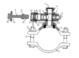
1は分水栓本体で、側部に配水支管との連結開口部11に連結構成された嵌着継手4と球弁13を介して球弁操作機構12が構成され、球弁13の上部に垂直方向の穿孔機挿入孔14、中央部は球弁13を操作機構12と掛合して収容する球弁格納部15となっていて、給水本管Aから連結開口部11を通じて配水支管に分水する分水機構が構成されている。
【0014】
嵌着継手4は、分水栓胴の連結開口部11から張出する継手枠41に着合してワンタッチ嵌着機構を構成するストッパーリング42、これを固定する止め輪43、嵌着機構部を密閉するL字形パッキン44といった部材が継手キャツプ45によって嵌装され、配水支管の端部が挿入されるとワンタッチで分水栓に着合するようになっている。
【0015】
即ち、嵌着継手4に配水支管の端部が挿入されると、挿入部によってストッパーリング42が押し広げられ、その内側に複数並列して設定された挿入方向に傾斜するテーパー段部46、46・・が挿入管の外周に圧接されて抜去できなくなる構造となっている。なお、継手4は上記のようなワンタッチ嵌着継手でなくても良いことは勿論である。
【0016】
2は分水源となる給水本管を挟着包持するサドルの上部包持体で、給水本管Aの下側に挿し回わされた下部包持体3とボルト21、ナット31により着合して給水本管を挟着包持するものである。
【0017】
分水栓の取り付けは、継手が付設されていない場合には下部包持体3を給水本管Aの下側に挿し回わして、上部包持体2と着合して配水本管を挟着包持して取り付け、頂部のキャップ6をはずし球弁13を回動して上下方向に穿孔機挿入孔14を通して上部から穿孔機を挿入できる状態として、連結開口部11をキャップ6で閉塞して給水本管に通水孔7を穿孔する。
【0018】
しかし、継手が付設されていると、連結開口部11をキャップ6で閉塞するためには、嵌着機構を構成するストッパーリング42、止め輪43、L字形パッキン44、継手キャツプ45といった部材を全て取り外し、嵌着機構が取り付けられていた栓本体の基部開口部を閉栓キャップで閉鎖しなければ穿孔できない。
【0019】
本発明による嵌着継手付サドル分水栓は、連結開口部11から張出する継手枠41の内壁に閉栓プラグ5の雄螺子51と螺合する雌螺子16を刻設し、閉栓プラグ5を継手4の着合管挿入側から挿入螺進させて着合管継手孔を密栓できるようにしたものである。
【0020】
閉栓プラグ5は、先端部にOリング52と分水栓本体継手嵌着部内壁に刻設された雌螺子16と螺合する雄螺子51を設定し、後端部にフランジ部53を設け、その内側に分水栓本体継手部の着合管挿入部端面と密接するシートパッキン54が設定されている。
【0021】
また、他の実施例として本体軸芯に穿孔時に発生する切粉を排出する切粉排出孔55を設け、閉栓プラグ5の軸芯からも切粉が排出されるようにして穿孔時に発生する切粉の排出をより完全なものとした。
【0022】
本発明による分水栓の取り付けは、下部包持体3を給水本管Aの下側に挿し回わして、上部包持体2と着合して配水本管を挟着包持して取り付け、頂部のキャップ6をはずし球弁13を回動して上下方向に穿孔機挿入孔14を通して上部から穿孔機を挿入できる状態として、閉栓プラグ5を分水栓継手4の着合管挿入側から挿入螺進させて球弁13の連結開口部11への連絡孔17まで挿入する。
【0023】
上記の閉栓プラグ5の挿入によって、プラグ先端部のOリング52が分水栓本体機構部と継手4の着合管挿入機構部との間を密封し、シートパッキン54が分水栓本体継手部の着合管挿入部端面と密接して、切粉の侵入や漏水が防止される。
【0024】
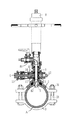
分水栓1の上部から穿孔機挿入孔14を通して、先端部に切粉排出バルブ81を備えた穿孔機8を挿入して切粉排出バルブ81を開栓し穿孔機のドリル82の回動すれば、ドリル82の回動によって発生する切粉は、給水本管Aの給水圧によって図2に示す矢印の経路を辿り、排出バルブ81を通じて排出され、給水本管Aに通水孔7が穿孔される。
【0025】
図3は、前記他の実施例により閉栓プラグ5の軸芯に切粉排出孔55を設けた場合の切粉排出経路を示すもので、切粉は図3に示す矢印の経路を辿り、ドリル回動部の直上に開口する排出孔55から直ちに排出され、残留されたものが排出バルブ81から排出される。
【0026】
給水本管に通水孔7を穿孔した後、球弁13の回動操作を可能とする上部位置で穿孔機を留めて穿孔された通水孔7からの水流を止めた状態で球弁13を回動して穿孔機挿入孔14を閉鎖し、キャップ6を嵌めた後に再び球弁13を回動して穿孔機挿入孔14を解放して分水を完了するものである。
【0027】
本発明は以上のように構成したので、継手付サドル分水栓の継手構造部材を取り外すことなく、閉栓プラグによる閉栓で給水本管に通水孔を不断水穿孔することができ、故障や漏水の原因となる各機構部への切粉の侵入を防止することができたものである。
【図面の簡単な説明】
【図1】本発明の実施例による嵌着継手付サドル分水栓と閉栓プラグの関係を示すサドル分水栓と閉栓プラグの縦断面正面図
【図2】同じく、閉栓プラグにより分水栓継手部を閉栓し、穿孔機を挿入した状態における一部を切欠断面として示した全体正面図
【図3】同じく、他の実施例による閉栓プラグにより分水栓継手部を閉栓し、穿孔機を挿入した状態における一部を切欠断面として示した全体正面図
【符号の説明】
1 分水栓本体
11 配水支管(着合管)との連結開口部
12 球弁操作機構
13 球弁
14 穿孔機挿入孔
15 球弁格納部
16 閉栓プラグの雄螺子と螺合する雌螺子
17 球弁の連結開口部への連絡孔
2 上部包持体
21 ボルト
3 下部包持体
31 ナット
4 嵌着継手
41 分水栓胴の連結開口部から張出する継手枠
42 ストッパーリング
43 ストッパーリングを固定する止め輪
44 L字形パッキン
45 継手キャツプ
46 ストッパーリングのテーパー段部
5 閉栓プラグ
51 雄螺子
52 Oリング
53 フランジ部
54 シートパッキン
55 切粉排出孔
6 キャツプ
7 通水孔
8 通水孔穿孔機
81 切粉排出バルブ
82 穿孔機のドリル
A 給水本管[0001]
[Industrial applications]
BACKGROUND OF THE INVENTION 1. Field of the Invention The present invention relates to a saddle water faucet with a joint, and more particularly to a saddle water faucet with a fitting joint and a plug for use in the same.
[0002]
[Prior art]
Conventionally, when a water distribution pipe is connected to a saddle water tap, a separately configured joint has been used. However, recently, a water pipe directly connected to a water tap (for example, Patent Document 1) has been proposed. It has been developed and is widely used.
[0003]
Further, after attaching the saddle water tap to the water supply main pipe, in order to perforate a water distribution hole in the water supply main pipe, a cap at the top of the water tap is removed, and a drilling machine is inserted from above to perform the drilling. 2), but the discharge of chips generated at the time of drilling depends exclusively on the blowing force due to the water supply pressure of the water supply main pipe, and no special consideration is given.
[0004]
[Patent Document 1] JP-A-8-53861 [Patent Document 2] 2003-96834 Patent
[Problems to be solved by the invention]
However, when a saddle water tap with a fitting, particularly a fitting fitting called a one-touch fitting, is directly configured in the water tap, the opening end of the one-touch fitting mechanism can be formed by drilling a water hole in the water supply main pipe. There is a problem that swarf generated at the time of perforation simply enters the fitting mechanism or the water faucet mechanism simply by closing with the cap.
[0006]
Therefore, if the discharge of the chips generated at the time of drilling was dependent only on the blowing force due to the water supply pressure of the water supply mains, the removal of the chips was insufficient, and in particular, the material of the water supply mains to be drilled was not sufficient. Some of them are mixed into drinking water and reach the end-of-stream equipment, and it has been required to remove chips more completely.
[0007]
In addition, even if the chips are not mixed into the drinking water, if they enter the surroundings of the ball valve, which is the mechanism of the water faucet, the ball seat, or the fitting mechanism, the mechanism may cause biting or poor connection. It may cause water leakage or failure.
[0008]
Further, since the discharge of chips generated during drilling depends on the blowing force of the water supply pressure of the water supply main pipe, the pipe insertion lubricant applied to the L-shaped packing in the pipe joint at the time of chip discharge is subjected to hydraulic pressure. There is a problem that is washed away by.
[0009]
In order to cope with the above inconveniences, when drilling a water distribution hole in a water supply main pipe, a great deal of effort is required to apply a
[0010]
[Means for Solving the Problems]
SUMMARY OF THE INVENTION The present invention has been made to address the above-described problem, and has a female screw carved on the inner wall of a fitting portion of a saddle faucet with a fitting joint, and a male screw screwed to the O-ring and the female screw at a tip portion. Insert the stopper plug with a screw into the fitting pipe insertion side and screw it tightly to close the fitting pipe joint hole, insert a drilling machine from the top of the water faucet main body, and pierce the water supply main pipe. It was configured to be.
[0011]
Further, a male screw which is screwed with an O-ring and a female screw engraved on the inner wall of the fitting body of the water faucet main body is set at the distal end portion of the plug, and a flange portion is provided at the rear end portion. It is configured to set a sheet packing that is in close contact with the end face of the fitting pipe insertion part of the faucet main body joint, to enhance the close contact structure between the faucet and the closure plug, and the tip of the closure plug is the faucet mechanism To prevent the intrusion of chips into the water faucet mechanism and the intrusion of chips into the joint fitting mechanism.
[0012]
In addition, a chip discharge hole for discharging chips generated at the time of drilling is provided in the plug body of the plug body, and the chip contacts the L-shaped packing set in the joint fitting mechanism through the chip discharge hole. The lubricating oil for pipe insertion provided on the L-shaped packing is prevented from flowing by the water pressure.
[0013]
BEST MODE FOR CARRYING OUT THE INVENTION
Hereinafter, embodiments of the present invention will be described with reference to the drawings.
1 is a main body of a water faucet, and a ball valve operating mechanism 12 is configured through a fitting joint 4 and a
[0014]
The fitting joint 4 is fitted to a
[0015]
That is, when the end of the water distribution branch pipe is inserted into the fitting joint 4, the
[0016]
[0017]
To install the water faucet, when no joint is provided, the lower holding body 3 is inserted around the lower side of the water supply main pipe A and is attached to the
[0018]
However, when the joint is provided, in order to close the connection opening 11 with the cap 6, all of the members such as the
[0019]
In the saddle water tap with a fitting joint according to the present invention, a
[0020]
The stopper plug 5 has an O-
[0021]
Further, as another embodiment, a
[0022]
In the installation of the water faucet according to the present invention, the lower holding body 3 is inserted around the lower side of the water supply main pipe A, is attached to the
[0023]
By the insertion of the stopper plug 5, the O-
[0024]
A
[0025]
FIG. 3 shows a chip discharge path in a case where a
[0026]
After piercing the water supply hole 7 in the water supply main pipe, the piercing machine is stopped at an upper position where the
[0027]
Since the present invention is configured as described above, the water supply hole can be continuously drilled in the water supply main pipe by plugging with a plug plug without removing the joint structural member of the saddle split faucet with a joint, and failure or water leakage can be prevented. Thus, it is possible to prevent chips from entering into each mechanism, which causes the above.
[Brief description of the drawings]
FIG. 1 is a longitudinal sectional front view of a saddle water faucet and a plug showing a relationship between a saddle water faucet with a fitting joint and a plug according to an embodiment of the present invention. FIG. FIG. 3 is an overall front view showing a partially cut-away section in a state in which a part is plugged and a drilling machine is inserted. FIG. Whole front view showing a cut-away cross-section of a part in a broken state
1 water tap main body 11 connection opening 12 with water distribution branch pipe (joining pipe) 12 ball
Claims (4)
Priority Applications (1)
| Application Number | Priority Date | Filing Date | Title |
|---|---|---|---|
| JP2003128576A JP3798763B2 (en) | 2003-05-07 | 2003-05-07 | Water hole drilling method, water plug and plug for saddle water tap with fitting |
Applications Claiming Priority (1)
| Application Number | Priority Date | Filing Date | Title |
|---|---|---|---|
| JP2003128576A JP3798763B2 (en) | 2003-05-07 | 2003-05-07 | Water hole drilling method, water plug and plug for saddle water tap with fitting |
Publications (2)
| Publication Number | Publication Date |
|---|---|
| JP2004332811A true JP2004332811A (en) | 2004-11-25 |
| JP3798763B2 JP3798763B2 (en) | 2006-07-19 |
Family
ID=33504653
Family Applications (1)
| Application Number | Title | Priority Date | Filing Date |
|---|---|---|---|
| JP2003128576A Expired - Fee Related JP3798763B2 (en) | 2003-05-07 | 2003-05-07 | Water hole drilling method, water plug and plug for saddle water tap with fitting |
Country Status (1)
| Country | Link |
|---|---|
| JP (1) | JP3798763B2 (en) |
Cited By (3)
| Publication number | Priority date | Publication date | Assignee | Title |
|---|---|---|---|---|
| FR2885400A1 (en) * | 2005-05-09 | 2006-11-10 | Equip Ind Europ Sa | Water cut device for use with drinking water service pipe, has control part pressurized to pressure greater than pressure in fluid zone, for collapsing deformable sleeve and blocking fluid zone |
| FR2974825A1 (en) * | 2011-05-03 | 2012-11-09 | Sade Cie Generale De Travaux D Hydraulique | Installation for replacing probe placed on e.g. underground water pipe, has key cooperating with probe to assemble/disassemble probe when key is actuated from ground surface, and move probe with key when key is moved up/down via access tube |
| KR101664028B1 (en) * | 2015-12-21 | 2016-10-10 | 조규성 | Ferrule which has function for preventing water leakage and cut-off function of water supply |
-
2003
- 2003-05-07 JP JP2003128576A patent/JP3798763B2/en not_active Expired - Fee Related
Cited By (3)
| Publication number | Priority date | Publication date | Assignee | Title |
|---|---|---|---|---|
| FR2885400A1 (en) * | 2005-05-09 | 2006-11-10 | Equip Ind Europ Sa | Water cut device for use with drinking water service pipe, has control part pressurized to pressure greater than pressure in fluid zone, for collapsing deformable sleeve and blocking fluid zone |
| FR2974825A1 (en) * | 2011-05-03 | 2012-11-09 | Sade Cie Generale De Travaux D Hydraulique | Installation for replacing probe placed on e.g. underground water pipe, has key cooperating with probe to assemble/disassemble probe when key is actuated from ground surface, and move probe with key when key is moved up/down via access tube |
| KR101664028B1 (en) * | 2015-12-21 | 2016-10-10 | 조규성 | Ferrule which has function for preventing water leakage and cut-off function of water supply |
Also Published As
| Publication number | Publication date |
|---|---|
| JP3798763B2 (en) | 2006-07-19 |
Similar Documents
| Publication | Publication Date | Title |
|---|---|---|
| AU2007284046A1 (en) | Friction bolt and expansion adaptor for said anchor | |
| JP5411964B2 (en) | Branch joint | |
| JP2004332811A (en) | Water divide port boring method in saddle snap tap with joint, snap tap and snap tap closing plug | |
| US6260573B1 (en) | Pipe-drilling fitting | |
| JP2007170661A (en) | Saddle tap | |
| US20050247344A1 (en) | Device for producing bypasses under pressure in fluid piping systems | |
| JP3266890B2 (en) | Replacement method of water pipe branch tap and apparatus used in the method | |
| JP2002323190A (en) | Saddle ferrule and method of boring | |
| JP2011132994A (en) | Pipe connector | |
| KR20100035373A (en) | Diverging apparatus | |
| JPH09155610A (en) | Boring jig for branch | |
| JP2003287183A (en) | Diversion saddle joint | |
| JP3667629B2 (en) | Saddle water faucet for resin pipe | |
| JP4656368B2 (en) | Continuous flow closure method | |
| JP4537359B2 (en) | Dividing cover joint | |
| KR200227722Y1 (en) | One touch plug and flange for piercing pipe | |
| JP4363591B2 (en) | Water stop method and water stop device for branch pipe | |
| JP3185876U (en) | Saddle tap with saddle | |
| JPH03504886A (en) | Sanitary mixer tap for installation on decorative surfaces | |
| US20060181082A1 (en) | Bullthread | |
| JP3336227B2 (en) | Branching method of resin pipe | |
| JP4480054B2 (en) | Piping return fitting | |
| JPH11166683A (en) | Service tee joint | |
| JP2000081137A (en) | Sealing plug, sealing plug for machining, and sealing method in machining fluid passing hole of metal mold member, and machining method for fluid passing hole of metal mold member | |
| JPH0656509U (en) | Pipe joint device |
Legal Events
| Date | Code | Title | Description |
|---|---|---|---|
| A977 | Report on retrieval |
Free format text: JAPANESE INTERMEDIATE CODE: A971007 Effective date: 20051027 |
|
| A131 | Notification of reasons for refusal |
Free format text: JAPANESE INTERMEDIATE CODE: A131 Effective date: 20051104 |
|
| A521 | Request for written amendment filed |
Free format text: JAPANESE INTERMEDIATE CODE: A523 Effective date: 20051116 |
|
| A02 | Decision of refusal |
Free format text: JAPANESE INTERMEDIATE CODE: A02 Effective date: 20060123 |
|
| A521 | Request for written amendment filed |
Free format text: JAPANESE INTERMEDIATE CODE: A523 Effective date: 20060209 |
|
| A911 | Transfer to examiner for re-examination before appeal (zenchi) |
Free format text: JAPANESE INTERMEDIATE CODE: A911 Effective date: 20060308 |
|
| TRDD | Decision of grant or rejection written | ||
| A01 | Written decision to grant a patent or to grant a registration (utility model) |
Free format text: JAPANESE INTERMEDIATE CODE: A01 Effective date: 20060404 |
|
| A61 | First payment of annual fees (during grant procedure) |
Free format text: JAPANESE INTERMEDIATE CODE: A61 Effective date: 20060420 |
|
| R150 | Certificate of patent or registration of utility model |
Ref document number: 3798763 Country of ref document: JP Free format text: JAPANESE INTERMEDIATE CODE: R150 |
|
| FPAY | Renewal fee payment (event date is renewal date of database) |
Free format text: PAYMENT UNTIL: 20100428 Year of fee payment: 4 |
|
| R250 | Receipt of annual fees |
Free format text: JAPANESE INTERMEDIATE CODE: R250 |
|
| FPAY | Renewal fee payment (event date is renewal date of database) |
Free format text: PAYMENT UNTIL: 20110428 Year of fee payment: 5 |
|
| R250 | Receipt of annual fees |
Free format text: JAPANESE INTERMEDIATE CODE: R250 |
|
| FPAY | Renewal fee payment (event date is renewal date of database) |
Free format text: PAYMENT UNTIL: 20120428 Year of fee payment: 6 |
|
| R250 | Receipt of annual fees |
Free format text: JAPANESE INTERMEDIATE CODE: R250 |
|
| FPAY | Renewal fee payment (event date is renewal date of database) |
Free format text: PAYMENT UNTIL: 20130428 Year of fee payment: 7 |
|
| R250 | Receipt of annual fees |
Free format text: JAPANESE INTERMEDIATE CODE: R250 |
|
| FPAY | Renewal fee payment (event date is renewal date of database) |
Free format text: PAYMENT UNTIL: 20140428 Year of fee payment: 8 |
|
| R250 | Receipt of annual fees |
Free format text: JAPANESE INTERMEDIATE CODE: R250 |
|
| R250 | Receipt of annual fees |
Free format text: JAPANESE INTERMEDIATE CODE: R250 |
|
| R250 | Receipt of annual fees |
Free format text: JAPANESE INTERMEDIATE CODE: R250 |
|
| R250 | Receipt of annual fees |
Free format text: JAPANESE INTERMEDIATE CODE: R250 |
|
| R250 | Receipt of annual fees |
Free format text: JAPANESE INTERMEDIATE CODE: R250 |
|
| R250 | Receipt of annual fees |
Free format text: JAPANESE INTERMEDIATE CODE: R250 |
|
| R250 | Receipt of annual fees |
Free format text: JAPANESE INTERMEDIATE CODE: R250 |
|
| R250 | Receipt of annual fees |
Free format text: JAPANESE INTERMEDIATE CODE: R250 |
|
| R250 | Receipt of annual fees |
Free format text: JAPANESE INTERMEDIATE CODE: R250 |
|
| R250 | Receipt of annual fees |
Free format text: JAPANESE INTERMEDIATE CODE: R250 |
|
| LAPS | Cancellation because of no payment of annual fees |