【0001】
【発明の属する技術分野】
本発明は、下水道用、通信線配設用、ガス管配設用などの管渠のマンホールに設備されるマンホール蓋及びマンホール蓋の受枠に関する。
【0002】
【従来の技術】
日本工業規格(JIS)では、車道上に設置されているマンホール蓋及びその受枠は、自動車が通過するときの荷重に耐えるねずみ鋳鉄製或いは黒鉛球状鋳鉄製であることを定めている(JIS A 5506,JIS G 5501,JIS G 5502)。そして、JIS A 5506の構造・機能の欄に、蓋と受枠との接触面には、がたつきがあってはならない旨の記載があり、JIS A 5506の付図1〜5には、マンホール蓋と受枠の接触面がテーパ面を有し、双方が密着し易い構造のマンホール蓋と受枠についての基準を定めている。
【0003】
ところで、従来から、マンホール蓋の上を自動車が通過したときにマンホール蓋の音鳴りが発生するという問題ある。この音鳴りは、マンホール蓋に荷重とくに偏荷重が加わったときや荷重の移動があったときに、マンホール蓋が振動する大きな金属音やその反響音であり、騒音による環境問題の1つに挙げられている。このため、この音鳴りについて様々な対策技術が検討されている。
この対策のための公知技術としては、例えば、マンホール蓋が接する受枠の内側下面にリング状のパッキンを入れてこのパッキンの上にマンホール蓋を配置させる技術(特開2003−141609号)、受枠の下面から内側周面に向けた個所に断面視L形状のリング状の騒音防止用パッキンを配設してマンホール蓋との接触面にこのパッキンを介在させる技術(実登3018612号)などがある。
【0004】
また、マンホール蓋及び受枠に関するもう1つの問題に、長年の使用につれ、鋳鉄部分の塗装が剥がれたり、磨耗が生じるなどして、マンホール蓋と受枠との密着面に錆が発生して密着面どうしが強固に付着して、マンホール蓋が開け難くしている問題がある。
従来、このような錆による付着を防ぐ事前対策として、定期的にマンホール蓋を開けてマンホール蓋の外周面と受枠の密着面にあたる部分の錆をブラシで落とし、この部分に防錆剤を塗る方法が知られており、事後対策として、マンホール蓋と受枠の錆び付いた密着面に錆剥離剤を浸透させて分離させる方法、マンホール蓋上面の周囲をハンマーで叩いて、錆で付着した部分を離脱させる方法などが知られている。
【0005】
【発明が解決しようとする課題】
しかしながら、前述したマンホール蓋の音鳴り防止に関し、特開2003−141609号公報に記載のマンホール蓋構造のように、マンホール蓋と受枠の接触面がテーパ状を有する構造において、マンホール蓋の外周下面と受枠の間にパッキンを入れると、パッキンが新しいときにはマンホール蓋な外周面と受枠とに間に隙間が生じ、ここから砂や土などが浸入してパッキンを損傷させる。このため、頻繁にパッキンを交換する必要が生じる。
また、パッキンの永年経過に伴う劣化や変形などによって厚みに差が生じて、双方のテーパ面が接触して、パッキンによる防振作用を失わせる。
これに対し、実登3018612号公報に記載のように、断面視L形状のパッキンを使用すると、上述した問題が更に大きくなる。
マンホール蓋と受枠に防錆剤を塗る方法は、防錆剤による効果が減退するため定期的にこれを行なう必要があるが、数多く設置されているマンホール蓋を定期的に点検してこれを行なうには人件費等の負担が大きく、特に自動車の通行量が多い車道上での点検には困難が多く、この事前対策は積極的に実施されていなかった。
事後対策としてマンホール蓋と受枠の間に剥離剤を流し込み、時間をかけて剥離材がもつ剥離作用で錆を落とす方法は、剥離剤の浸透による効果が発揮するまでに通常30分〜24時間程度要するために、多くの場合この時間が待てない。
マンホール蓋の上面の周囲をハンマーで叩いて、錆で付着している部分を離す方法は、マンホール蓋や受枠を変形させることがあり、好ましくない。
【0006】
本発明者は、上述した前者の問題が環境悪化を招き、後者の問題がマンホール蓋などの管理及びメンテナスにコスト負担と作業負担を生じさせていることに鑑み、これらを改善するにはどのようにすれば良いのかについて工夫を重ね、これらについて鋭意検討した。そして、その結果、ついに本発明を完成するに至った。
【0007】
このような経緯を経て完成した本発明は、自動車の通過時に発生するマンホール蓋の音鳴りによる騒音を防ぐとともに、マンホール蓋と受枠の密着面に錆が発生してこの密着面が強固に付着して、マンホール蓋を開けようとしても容易に開けられない事態になるのを防ぐマンホール蓋及びマンホール蓋の受枠を提供することを課題とする。
【0008】
【課題を解決するための手段】
以上の課題を解決する手段である請求項1に記載の発明によるマンホール蓋は、フランジ部の上端若しくはその近傍個所から下端に向かうに従って小径になるテーパ状の傾斜面にて形成された外周面を有するマンホール蓋本体の該外周面に、アルミニウム、ステンレス、ニッケル、亜鉛、またはこれらいずれかを主材料とする合金、カーボン焼結合金、プラスチック、合成ゴム、フッ素系樹脂のうちのいずれか又は複数を材料とする保護材が設けられていることを特徴とする。
【0009】
本発明の請求項1に記載のマンホール蓋は、マンホール蓋本体に保護材が設けられたものであり、マンホール蓋本体は、マンホール蓋を閉じたときにその外周面が受枠の内周面に互いに傾斜した同じ向きで密着して閉じるテーパ構造を持つものが該当する。
保護材はマンホール蓋の外周面に設けられ、肉厚の薄い保護材やフッ素系樹脂の保護材を用いる場合には、従来技術によるこの種のマンホール蓋がそのままマンホール蓋本体として用いられる。肉厚の厚い保護材を用いられる場合には、フランジ部の外周面に保護材を設けた状態で受枠内に丁度嵌まるように、若干外径の小さなマンホール蓋本体を用い、マンホール蓋では、その外周面に保護材の厚み方向の一部が嵌まる溝又は段部が形成されたものを用いる。
【0010】
保護材は、マンホール蓋本体のフランジ部の外周面と受枠との間に介在させる緩衝材としての機能と、この外周面と受枠が錆びにより付着しないようにするための隔壁材としての機能を有する。緩衝材としての機能は、マンホール蓋の音鳴りを極力防ぎ、また、吸収する。隔保護材としての機能は、マンホール蓋と受枠の密着面のいずれか一方の面に錆びない材料を用いていることにより発揮する。
請求項1に記載の各材料はこれら機能を有し、各材料に見合った肉厚を有し、マンホール蓋の外周面に、直接又はマンホール蓋の塗装面に、固定又は着脱自在に設けられる。請求項1に記載の保護材では、その形状や数を問わない。
【0011】
次に挙げる請求項2に記載のマンホール蓋では、上記構成を有するマンホール蓋であって、保護材にはフランジ部の外周面に沿うリング板状又はC形板状を有するものが用いられている。
【0012】
請求項2に記載の保護材のうち、リング状の保護材は、鋳鉄製のマンホール蓋本体に嵌め入れて固定できるので、マンホール蓋本体のフランジ部の外周面に沿った固定がし易くなる。また、保護材に継ぎ目が無いので、フランジ部の外周面から離脱したり剥がれたりし難くなる。C形板状の保護材は、フランジ部の外周面、とくに外径に合わせた大きさに広げたり狭くするという若干の調整ができるので、マンホール蓋本体の外周径に合わせた固定ができる。また、蝶番を支点として開閉するマンホール蓋本体にも固定できる。なお、フッ素系樹脂を素材とする保護材は、マンホール蓋本体の外周面に塗布することにより設けられるので、請求項2の保護材には該当しない。
【0013】
次に挙げる請求項3に記載のマンホール蓋は、請求項1又は2に記載のマンホール蓋であって、フランジ部の外周面の上端部分が、フランジ部の外周面に沿わせて設けた保護材の上端面の少なくとも一部分が被さる方向に突出した形状を有する。
【0014】
マンホール蓋を受枠内に入れたときに、マンホール蓋の上端の周囲と受枠の間に若干の隙間が生じるが、マンホール蓋に設けられている保護材の肉厚が厚くなると、この厚みに相当する大きな隙間が生じ、この隙間から保護材の上方に向けて砂等が詰まって、マンホール蓋を開け難くする。請求項3に記載のマンホール蓋ではこのような事態になるのを防ぐため、フランジ部の外周面の上端部分を、保護材の上端面の少なくとも一部分が被さる方向に突出させて、この上端部分の周縁と受枠との間に生じる隙間が狭くなるようにした。このように保護材の上端面にフランジ部の外周面の上端部分を位置させると、気温の変化による保護材の膨張、永年経過による保護材の拡張などが生じたり、粘着剤等による固定力が減退しても、保護材がマンホール蓋から上方に抜け外れるという危険な事態には至らない。
【0015】
次に挙げる請求項4に記載の発明は、請求項1乃至3のいずれかに記載のマンホール蓋であって、保護材が、加熱膨張及び収縮を利用した嵌め込み、圧入、接着剤による接着、ねじ止め、ビス止め、塗布のうちの1又は複数の手段によりフランジ部の外周面に向けて固定されている。
【0016】
請求項1乃至3の構成では、保護材をどのような手段でマンホール蓋の外周面に設けるのかについての具体的な記載はないが、この固定をどのようにして行なうのかについて明確にすることが望ましく、これを請求項4において明記した。
なお、保護材として長尺板状のものを用いても良く、この場合には、保護材をマンホール蓋のフランジ部の外周面に1重又は多重に巻き付けて上記いずれか又は複数の方法で固定する。このようにすると、保護材をフランジ部の外周面にしっかりと固定できる。
【0017】
次に挙げる請求項5に記載の発明は、マンホール蓋の外周面を受けるテーパ状の傾斜面からなる内周面を有する受枠であって、該内周面に沿って、アルミニウム、ステンレス、ニッケル、亜鉛、又はこれらいずれかを主材料とする合金、カーボン焼結合金、プラスチック、合成ゴム、フッ素系樹脂のうちのいずれか又は複数を材料とする保護材が設けられていることを特徴とする。
【0018】
マンホール蓋の音鳴りによる騒音を無くし、マンホール蓋と受枠の密着面が錆で付着しないようにするためには、保護材をマンホール蓋に設けなくても、マンホール蓋が接する受材の内周面に設けても解決でき、これについて請求項5にて記載した。保護材の固定は請求項4に記載の技術によるものが望ましい。また、保護材を受枠だけでなくマンホール蓋と受材の双方に設けても良い。
【0019】
【発明の実施の形態】
本発明の実施の形態を添付図面に沿って詳述する。図1は本発明の第1実施形態によるマンホール蓋とその受枠を示し、図2は保護材を示し、図3は受枠を示し、図4は図1の要部を拡大して示す。
【0020】
図1に示す本発明の第1実施形態によるマンホール蓋1は、鋳鉄製のマンホール蓋本体1aの外周面1bにリング状の保護材3が設けられたもので構成され、マンホール蓋本体1aと保護材3とが一体となって受枠2内に嵌め入れられている。
図1及び図2に示すように、保護材3は、マンホール蓋本体1aの外周面に沿う大きさの断面視板形状を持つリング状を有し、比較的肉厚が薄い形状を有するアルミニウム、ステンレス、ニッケル、亜鉛、又はこれらいずれかを主材料とする合金、カーボン焼結合金、プラスチック、合成ゴムのうちの何れかの材料で形成されている。
マンホール蓋本体1aは、平面視において略円板形状を有し、その外周端から下方に向けて上端から下端に向かうに従って若干、小径になるテーパ状を有する外周面1bを持つ外周壁が形成され、外面全体に塗料が塗られて防錆された鋳鉄製のものである。
【0021】
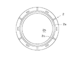
図1及び図3に示す受枠2は、受枠本体2aの内側にマンホール蓋1を嵌め入れることができる大きさの段付開口2bが形成され、この段付開口2bを形成している上部側の内周面2cが、マンホール蓋1の外周面1bと同じ傾斜角を持つ斜面にて形成された鋳鉄製のものであり、この受枠2も塗料が塗られて防錆されている。
【0022】
図3及び図4に示すように、保護材3は、マンホール蓋本体1aの外周面1bに沿って嵌め入れられて接着剤4で外周面1bから下方に抜け外れないように固定されている。尚、接着材4の代わりに両面粘着テープで固定してもよい。また、保護材3の肉厚が厚い場合には、ビスの頭部を保護材4に埋め込むようにして、保護材3をマンホール本体1aにビス止めしてもよい。
【0023】
保護材3として用いられているプラスチックは、寸法安定性、耐衝撃性、耐磨耗性、耐溶剤性、耐候性、耐熱性、耐寒性などに優れ、経年劣化し難い材質のものが好ましく、必ずしも限定されるものではないが、例えば、ポリエチレン、ポリプロピレン、塩化ビニル、ABS樹脂、ナイロン、ポリカーボネイト、ポリアセタール、ポリイミド、ポリスルフォン、PET、PBT、PTFE,ETFE、PVOF、ポリアリレート、セルロース・アセテート樹脂、フェノール樹脂、メラミン樹脂、ユリア樹脂、不飽和ポリエステル、エポキシ樹脂、エチレン−プロピレン共重合体樹脂、エチレン酢酸共重合体樹脂、酢酸セルロース樹脂、セルロース・アセテート・ブチレート、エチルセルロース樹脂、などが挙げられる。
また、エラストマー、フッ素系樹脂を用いても良い。この他、これらいずれか又は複数の材料に、ガラス繊維、ボロン繊維、炭素繊維、セラミック繊維などのいずれか又は複数の材料を加えて強化プラスチックにしたものを用いても良い。プラスチックに代えて金属製の保護材を用いるときには、アルミニウム、ステンレス、ニッケル、亜鉛、又はこれらいずれかを主材料とする合金を用いる。この他にも、防錆面と滑り特性に優れたカーボン焼結合金製の保護材を用いてもよい。
【0024】
このようにすると、図4に示すように、マンホール蓋1を受枠2の開口2b内に嵌め込んだとき、マンホール蓋1の外周面1bと受枠2の開口2bの内周面2cとは、保護材3を挟んだ状態で密着する。
このため、マンホール蓋1の上を自動車が通過して、マンホール蓋1に荷重とくに荷重の移動があってマンホール蓋1に振動が発生しても、この保護材3がマンホール蓋1と受枠2との間でクッションとなって、音鳴りを防ぐことができる。
【0025】
また、マンホール蓋本体1aと受枠2の間に保護材3が位置しているため、マンホール蓋本体1aと受枠2に錆が発生しても、錆で付着してマンホール蓋1が受枠2内から取り出し難くなるようなことはない。このためマンホール蓋1及びその周辺の管理が長期間されていない状態でも、マンホール蓋1は容易に開けられる。
【0026】
なお、マンホール蓋1は、この保護材3を挟んだ状態で受枠2の斜面2cの途中で止まった状態になってその下方に隙間Pがあるため、保護材2が永年経過により磨耗したり、保護材3やマンホール蓋1が季節の温度変化によって膨張や収縮しても、マンホール蓋1と受枠2の双方のテーパ面どうしの上下の接触位置がズレることで、双方の密着性は維持される。
【0027】
図4に示す保護材3は、マンホール蓋本体1aの外周面1bの高さと同じ高さを持つものが使用されているが、保護材3の高さをマンホール蓋本体1aの外周面1bの高さよりも低い形状のものを用いて、外周面1bの途中に嵌め付けてもよい。
【0028】
上述したように、保護材3は、マンホール蓋本体1aの外周面1bと同じ傾斜角のテーパ面を持っているため、マンホール蓋本体1aの外周面1bに取り付けて受枠2内に嵌め込んでも、上方に抜け外れることはない。
【0029】
ところで、マンホール蓋本体1aの外周形状は上述した形状のものだけに限定されない。例えば、第2実施形態として図5に示すマンホール本体1aのように、その外周面1bの上端部分1dを残す下部分の外周面を、若干小径になる段部1eに形成し、この段部1eに保護材3を嵌め付けて、保護材3の上端面の少なくとも一部分をマンホール蓋本体1aの上端部分1dで被せるようしてもよい。
このようにすると、保護材3の上方の隙間に砂や土が入り難くなり、特に、保護材3の肉厚が比較的厚い場合に有効である。また、周囲の環境温度の変化によって保護材3が膨張しても、上方に抜け外れない。また、接着剤などの固定手段を使用しないで保護材3をマンホール蓋本体1aの下方から嵌め入れても、上方に抜け外れない。このため、保護剤3の交換作業がし易くなる。
【0030】
また、図6に示すように、マンホール蓋本体1aの外周面1bにフッ素系樹脂を素材とする保護材30を塗布により固定してもよい。
【0031】
更に本発明では、保護材をマンホール蓋に設けないで、その受枠に設けることによっても、上述した構造と同じ機能を得ることができる。
図7は受枠内に保護材と配置した状態の要部を拡大して示している。図7に示す受枠20は、マンホール蓋を嵌め入れることができる大きさの段付開口2bが形成され、この段付開口2bを形成している上部側の内周面2cが、マンホール蓋1の外周面1bと同じ傾斜角を持つ斜面にて形成された鋳鉄製のものが用いられ、この受枠2も塗料が塗られて防錆されている。そして、この内周面2cに、図2に示す保護材3と同じ形状及び素材で形成された保護材3を配置させてある。
このようにすると、図8に示すように、マンホール蓋10を受枠20の開口2b内に嵌め込んだとき、マンホール蓋10の外周面1bと受枠20の開口2bの内周面2cとは、保護材3を挟んだ状態で密着する。つまり、上述したマンホール蓋1に保護材3を固定したときと同じ状態になり、同じ機能をもたらす。
【0032】
【発明の効果】
以上、説明した本発明のマンホール蓋や受枠によれば、双方に密着面の間に保護材を設けているため、自動車の通過時に発生するマンホール蓋の音鳴りがこの保護材があることによって防いだり、極力、抑えることができる。また、マンホール蓋と受枠の密着面に錆が発生しても、保護材があることによって、双方の密着面が錆によって強固に付着してマンホール蓋が容易に開けることができないといった事態も防ぐことができる。
特に、本発明では、マンホール蓋の外周面と受枠の内周面が持つテーパ面に保護材を介在させているため、マンホール蓋と受枠の間の隙間を無くしたり、極力狭くすることができる。この結果、マンホール蓋の外周面と受枠の間から砂や土が浸入して、マンホール蓋が開け難くなるといった事態も極力抑えることができる。
このように本発明では、テーパ形状を持つマンホール蓋の外周面或いは受枠の内周面にリング状の保護材を設けたことによって、マンホール蓋の外周面と受枠の内周面とによる密着効果である、砂や土の浸入を極力防ぎ、マンホール蓋に安定した支持などを維持させることができる。また、テーパ面に保護材を支持させているので、交換も容易にでき、保護材の形状も簡単になっているため、低コストでその効果を得ることができる。
【図面の簡単な説明】
【図1】本発明の第1実施形態によるマンホール蓋とその受枠を示した側面断面図である。
【図2】保護材を示した斜視図である。
【図3】受枠を示した平面図である。
【図4】図1の要部拡大図である。
【図5】本発明の第2実施形態によるマンホール蓋とその受枠を示した要部拡大断面図である。
【図6】本発明の第2実施形態によるマンホール蓋とその受枠を示した要部拡大断面図である。
【図7】受枠内に保護材と配置した状態を示した要部拡大断面図である。
【図8】同じくその内側にマンホール蓋を嵌め入れた状態を示した要部拡大側面図である。
【符号の説明】
1 マンホール蓋
1a マンホール蓋本体
1b 外周面
1d 外周壁
2 受枠
2b 段付開口
2c 内周面
3 保護材
4 接着材[0001]
TECHNICAL FIELD OF THE INVENTION
The present invention relates to a manhole cover and a receiving frame for a manhole cover installed in a manhole of a sewer for sewerage, for arranging communication lines, for arranging gas pipes, and the like.
[0002]
[Prior art]
Japanese Industrial Standards (JIS) stipulates that manhole covers and their receiving frames installed on roadways are made of gray cast iron or graphite spheroidal cast iron that can withstand loads when vehicles pass (JIS A 5506). , JIS G5501 and JIS G5502). And, in the column of the structure and function of JIS A 5506, there is a description that the contact surface between the lid and the receiving frame should not have rattling, and in FIGS. 1 to 5 of JIS A 5506, the manhole cover is shown. The contact surface between the manhole cover and the receiving frame has a tapered surface, and a standard for a manhole cover and a receiving frame having a structure in which both are easily adhered to each other is determined.
[0003]
By the way, conventionally, there is a problem that the sound of the manhole cover is generated when the vehicle passes over the manhole cover. This noise is a loud metal sound that vibrates the manhole cover when a load is applied to the manhole cover, especially when an eccentric load is applied or the load moves, and its reverberant sound. It is one of the environmental problems caused by noise. Have been. For this reason, various countermeasures against this noise are being studied.
As a known technique for this measure, for example, a technique of placing a ring-shaped packing on the inner lower surface of a receiving frame in contact with a manhole cover and disposing the manhole cover on the packing (Japanese Patent Laid-Open No. 2003-141609), There is a technique of arranging a ring-shaped noise-preventing packing having an L-shaped cross section at a position from the lower surface toward the inner peripheral surface and interposing the packing on a contact surface with a manhole cover (Japanese Utility Model No. 3018612).
[0004]
Another problem related to the manhole cover and the receiving frame is that, with the long-term use, the paint on the cast iron part is peeled off or abraded, and rust is generated on the contact surface between the manhole cover and the receiving frame. However, there is a problem that the manhole cover is difficult to open because of strong adhesion.
Conventionally, as a precautionary measure to prevent such adhesion due to rust, a method of periodically opening the manhole cover, brushing off the rust on the outer peripheral surface of the manhole cover and the contact surface of the receiving frame with a brush, and applying a rust inhibitor to this part As a post-mortem measure, a method is used in which a rust release agent is penetrated into the rusted contact surface of the manhole cover and the receiving frame to separate it, and the area around the upper surface of the manhole cover is hit with a hammer to remove the rust-attached part Methods are known.
[0005]
[Problems to be solved by the invention]
However, regarding the above-described prevention of noise from the manhole cover, in a structure in which the contact surface between the manhole cover and the receiving frame has a tapered shape, as in the manhole cover structure described in JP-A-2003-141609, If the packing is inserted between the receiving frames, when the packing is new, a gap is formed between the outer peripheral surface of the manhole cover and the receiving frame, and sand or soil or the like intrudes from the gap to damage the packing. Therefore, it is necessary to frequently replace the packing.
In addition, a difference in thickness occurs due to deterioration or deformation of the packing with the passage of time, and the two tapered surfaces come into contact with each other, so that the vibration damping action of the packing is lost.
On the other hand, as described in Japanese Unexamined Utility Model Publication No. 3018612, the use of a packing having an L-shape in sectional view further increases the above-described problem.
In the method of applying a rust inhibitor to the manhole cover and the receiving frame, it is necessary to do this periodically because the effect of the rust inhibitor decreases, but do this by regularly checking the many manhole covers installed However, there are many difficulties in conducting inspections, especially on roadways where there is a large amount of traffic, and this precautionary measure has not been actively implemented.
As a post-mortem measure, a method of pouring the release agent between the manhole cover and the receiving frame and removing the rust by the release action of the release material over time is usually about 30 minutes to 24 hours until the effect due to the penetration of the release agent is exhibited. In many cases, this time cannot be waited for.
The method of hitting the periphery of the upper surface of the manhole cover with a hammer to release the portion attached with rust is not preferable because the manhole cover and the receiving frame may be deformed.
[0006]
The present inventor considers that the former problem causes environmental degradation, and that the latter problem causes cost burden and work burden on management and maintenance of manhole covers and the like, and how to improve these problems is considered. We devised what we should do, and we scrutinized them. As a result, the present invention has been finally completed.
[0007]
The present invention completed through such a process not only prevents the noise caused by the sound of the manhole cover generated when passing through the car, but also generates rust on the contact surface between the manhole cover and the receiving frame, and the adhered surface is strongly adhered. It is another object of the present invention to provide a manhole cover and a receiving frame for the manhole cover that prevent a situation in which the manhole cover cannot be easily opened even when the manhole cover is opened.
[0008]
[Means for Solving the Problems]
The manhole cover according to the first aspect of the present invention, which is a means for solving the above problem, has an outer peripheral surface formed by a tapered inclined surface having a smaller diameter from the upper end of the flange portion or a portion near the upper end toward the lower end. The outer peripheral surface of the manhole cover body having, aluminum, stainless steel, nickel, zinc, or any one or more of these as the main material, carbon sintered alloy, plastic, synthetic rubber, one or more of the fluorine-based resin It is characterized in that a protective material as a material is provided.
[0009]
The manhole cover according to claim 1 of the present invention includes a manhole cover main body provided with a protective material, and the manhole cover main body has an outer peripheral surface on an inner peripheral surface of a receiving frame when the manhole lid is closed. The one having a tapered structure that closes in close contact in the same inclined direction corresponds to this.
The protective material is provided on the outer peripheral surface of the manhole cover. When a thin protective material or a fluororesin protective material is used, this type of manhole cover according to the related art is used as a manhole cover body as it is. When a thick protective material is used, a manhole cover body with a slightly smaller outer diameter is used so that the protective material is provided on the outer peripheral surface of the flange portion, so as to just fit into the receiving frame. The outer peripheral surface is formed with a groove or a step portion in which a part of the protective material in the thickness direction is fitted.
[0010]
The protective material has a function as a cushioning material interposed between the outer peripheral surface of the flange portion of the manhole cover main body and the receiving frame, and a function as a partition material for preventing the outer peripheral surface and the receiving frame from adhering due to rust. . The function as a cushioning material minimizes and absorbs the noise of the manhole cover. The function as a barrier protection material is exhibited by using a material that does not rust on either one of the contact surfaces of the manhole cover and the receiving frame.
Each material described in claim 1 has these functions, has a thickness corresponding to each material, and is fixed or detachably provided on the outer peripheral surface of the manhole cover directly or on the painted surface of the manhole cover. In the protective material according to the first aspect, the shape and the number are not limited.
[0011]
In the manhole cover according to the second aspect described below, the manhole cover having the above-described configuration is used, in which the protective material has a ring plate shape or a C-shaped plate shape along the outer peripheral surface of the flange portion. .
[0012]
Since the ring-shaped protective material of the protective material according to claim 2 can be fitted and fixed to the cast iron manhole cover main body, it can be easily fixed along the outer peripheral surface of the flange portion of the manhole cover main body. In addition, since the protective material has no seams, it is difficult for the protective material to be detached or peeled from the outer peripheral surface of the flange portion. Since the C-shaped plate-shaped protective material can be slightly adjusted to be widened or narrowed to the outer peripheral surface of the flange portion, particularly to the outer diameter, it can be fixed to the outer peripheral diameter of the manhole cover main body. It can also be fixed to a manhole cover body that opens and closes with a hinge as a fulcrum. Note that the protective material made of a fluororesin is provided by being applied to the outer peripheral surface of the manhole cover main body, and thus does not correspond to the protective material of claim 2.
[0013]
The following manhole cover according to claim 3 is the manhole cover according to claim 1 or 2, wherein the upper end portion of the outer peripheral surface of the flange portion is provided along the outer peripheral surface of the flange portion. Has a shape protruding in a direction in which at least a part of an upper end surface of the cover is covered.
[0014]
When the manhole cover is placed in the receiving frame, a slight gap is formed between the periphery of the upper end of the manhole cover and the receiving frame. However, when the thickness of the protective material provided on the manhole cover is increased, this corresponds to this thickness. A large gap is formed, and sand or the like is clogged from the gap toward the upper side of the protective material, making it difficult to open the manhole cover. In order to prevent such a situation from occurring in the manhole cover according to claim 3, the upper end portion of the outer peripheral surface of the flange portion is projected in a direction in which at least a portion of the upper end surface of the protective material is covered, and the upper end portion of the upper end portion is formed. The gap generated between the peripheral edge and the receiving frame is narrowed. When the upper end portion of the outer peripheral surface of the flange portion is positioned on the upper end surface of the protective material as described above, the protective material expands due to a change in temperature, the protective material expands over time, and the fixing force due to an adhesive or the like is reduced. Even if it declines, it does not lead to a dangerous situation in which the protective material comes off the manhole cover upward.
[0015]
The fourth aspect of the present invention described below is the manhole cover according to any one of the first to third aspects, wherein the protective material is fitted using heat expansion and contraction, press-fitted, bonded with an adhesive, and screwed. It is fixed toward the outer peripheral surface of the flange portion by one or more of stop, screw, and application.
[0016]
In the configuration of claims 1 to 3, there is no specific description of what means to provide the protective material on the outer peripheral surface of the manhole cover, but it is clear how to fix this. Desirably, this is specified in claim 4.
In addition, a long plate may be used as the protective material. In this case, the protective material is wrapped around the outer peripheral surface of the flange portion of the manhole cover in a single or multiple manner and fixed by any one or more of the above methods. I do. With this configuration, the protection member can be firmly fixed to the outer peripheral surface of the flange portion.
[0017]
The invention according to claim 5 described below is a receiving frame having an inner peripheral surface formed of a tapered inclined surface that receives the outer peripheral surface of the manhole cover, and along the inner peripheral surface, aluminum, stainless steel, nickel, A protective material is provided, which is made of any one or more of zinc or an alloy containing any one of these as a main material, a sintered carbon alloy, plastic, synthetic rubber, and a fluororesin.
[0018]
In order to eliminate the noise caused by the sound of the manhole cover and prevent the adhesion surface between the manhole cover and the receiving frame from sticking with rust, the inner peripheral surface of the receiving material that the manhole cover comes into contact with, even if no protective material is provided on the manhole cover Can be solved, and this is described in claim 5. The fixing of the protective material is desirably based on the technique described in claim 4. Further, the protective material may be provided not only on the receiving frame but also on both the manhole cover and the receiving material.
[0019]
BEST MODE FOR CARRYING OUT THE INVENTION
Embodiments of the present invention will be described in detail with reference to the accompanying drawings. FIG. 1 shows a manhole cover and its receiving frame according to a first embodiment of the present invention, FIG. 2 shows a protective material, FIG. 3 shows a receiving frame, and FIG. 4 shows an enlarged main part of FIG.
[0020]
A manhole cover 1 according to the first embodiment of the present invention shown in FIG. 1 is configured by providing a ring-shaped protective material 3 on an outer peripheral surface 1b of a manhole cover body 1a made of cast iron. The material 3 is integrally fitted into the receiving frame 2.
As shown in FIGS. 1 and 2, the protection member 3 has a ring shape having a plate-like cross-sectional shape having a size along the outer peripheral surface of the manhole cover main body 1 a, and aluminum having a relatively thin wall shape. It is formed of any material of stainless steel, nickel, zinc, or an alloy containing any of these as a main material, a carbon sintered alloy, plastic, and synthetic rubber.
The manhole cover main body 1a has a substantially disk shape in a plan view, and has an outer peripheral wall having an outer peripheral surface 1b having a tapered shape that gradually decreases in diameter from the upper end to the lower end from the outer end thereof. It is made of cast iron in which paint is applied to the entire outer surface to prevent rust.
[0021]
The receiving frame 2 shown in FIGS. 1 and 3 is formed with a stepped opening 2b large enough to fit the manhole cover 1 inside the receiving frame main body 2a, and is formed on the upper side forming the stepped opening 2b. The inner peripheral surface 2c is made of cast iron and is formed of a slope having the same inclination angle as the outer peripheral surface 1b of the manhole cover 1, and the receiving frame 2 is also coated with paint to prevent rust.
[0022]
As shown in FIGS. 3 and 4, the protective member 3 is fitted along the outer peripheral surface 1 b of the manhole cover main body 1 a and is fixed by the adhesive 4 so as not to come down from the outer peripheral surface 1 b. It should be noted that the adhesive 4 may be fixed with a double-sided adhesive tape. When the thickness of the protective material 3 is large, the head of the screw may be embedded in the protective material 4 so that the protective material 3 is screwed to the manhole body 1a.
[0023]
The plastic used as the protective material 3 is preferably a material that is excellent in dimensional stability, impact resistance, abrasion resistance, solvent resistance, weather resistance, heat resistance, cold resistance, etc., and is hardly deteriorated over time. Although not necessarily limited, for example, polyethylene, polypropylene, vinyl chloride, ABS resin, nylon, polycarbonate, polyacetal, polyimide, polysulfone, PET, PBT, PTFE, ETFE, PVOF, polyarylate, cellulose acetate resin, Examples include phenolic resins, melamine resins, urea resins, unsaturated polyesters, epoxy resins, ethylene-propylene copolymer resins, ethylene acetate copolymer resins, cellulose acetate resins, cellulose acetate butyrate, and ethylcellulose resins.
Further, an elastomer or a fluorine-based resin may be used. In addition, a reinforced plastic obtained by adding one or more materials such as glass fiber, boron fiber, carbon fiber, and ceramic fiber to one or more of these materials may be used. When a metal protective material is used instead of plastic, aluminum, stainless steel, nickel, zinc, or an alloy containing any of these as a main material is used. In addition, a protective material made of a carbon sintered alloy having an excellent rustproof surface and excellent sliding properties may be used.
[0024]
Thus, as shown in FIG. 4, when the manhole cover 1 is fitted into the opening 2b of the receiving frame 2, the outer peripheral surface 1b of the manhole cover 1 and the inner peripheral surface 2c of the opening 2b of the receiving frame 2 are protected. The material 3 is brought into close contact with the material 3 therebetween.
For this reason, even if the automobile passes over the manhole cover 1 and the manhole cover 1 is subjected to a load, particularly a load movement, and the manhole cover 1 is vibrated, the protective material 3 is kept in contact with the manhole cover 1 and the receiving frame 2. It can be a cushion between them to prevent noise.
[0025]
Further, since the protective material 3 is located between the manhole cover main body 1a and the receiving frame 2, even if rust is generated between the manhole cover main body 1a and the receiving frame 2, the manhole cover 1 adheres to the rust and the manhole cover 1 is removed from the inside of the receiving frame 2. There is nothing that makes it difficult to remove. Therefore, the manhole cover 1 can be easily opened even when the manhole cover 1 and its surroundings are not managed for a long time.
[0026]
The manhole cover 1 stops at the middle of the slope 2c of the receiving frame 2 with the protective member 3 interposed therebetween, and there is a gap P below the manhole cover 1. Therefore, the protective member 2 is worn out over time, Even if the protective material 3 or the manhole cover 1 expands or contracts due to seasonal temperature changes, the upper and lower contact positions of the tapered surfaces of both the manhole cover 1 and the receiving frame 2 are shifted, so that the adhesion between them is maintained. .
[0027]
The protective material 3 shown in FIG. 4 has the same height as the outer peripheral surface 1b of the manhole cover main body 1a, but the height of the protective material 3 is set to the height of the outer peripheral surface 1b of the manhole lid main body 1a. A lower shape may be used and fitted in the middle of the outer peripheral surface 1b.
[0028]
As described above, since the protective member 3 has a tapered surface having the same inclination angle as the outer peripheral surface 1b of the manhole cover main body 1a, even if it is attached to the outer peripheral surface 1b of the manhole cover main body 1a and fitted into the receiving frame 2, It does not come off upward.
[0029]
Incidentally, the outer peripheral shape of the manhole cover main body 1a is not limited to the above-described shape. For example, as in the manhole body 1a shown in FIG. 5 as the second embodiment, the outer peripheral surface of the lower portion of the outer peripheral surface 1b leaving the upper end portion 1d is formed in a step 1e having a slightly smaller diameter, and this step 1e is formed. Protective member 3 may be fitted to at least a part of upper end surface of protective member 3 with upper end portion 1d of manhole cover main body 1a.
This makes it difficult for sand or soil to enter the gap above the protection member 3, which is particularly effective when the thickness of the protection member 3 is relatively large. Further, even if the protective material 3 expands due to a change in the surrounding environmental temperature, it does not come off upward. Further, even if the protective material 3 is fitted from below the manhole cover main body 1a without using a fixing means such as an adhesive, the protective material 3 does not come off and come off. For this reason, the replacement work of the protective agent 3 becomes easy.
[0030]
As shown in FIG. 6, a protective material 30 made of a fluororesin may be fixed to the outer peripheral surface 1b of the manhole cover main body 1a by coating.
[0031]
Further, in the present invention, the same function as the above-described structure can be obtained by providing the protective material on the receiving frame without providing the protective material on the manhole cover.
FIG. 7 shows an enlarged view of a main part in a state where the protective material is arranged in the receiving frame. The receiving frame 20 shown in FIG. 7 has a stepped opening 2b large enough to fit the manhole cover, and the upper inner peripheral surface 2c forming the stepped opening 2b is Cast iron made of a slope having the same inclination angle as the outer peripheral surface 1b is used, and the receiving frame 2 is also coated with paint to prevent rust. The protective member 3 formed of the same shape and material as the protective member 3 shown in FIG. 2 is disposed on the inner peripheral surface 2c.
8, when the manhole cover 10 is fitted into the opening 2b of the receiving frame 20, the outer peripheral surface 1b of the manhole cover 10 and the inner peripheral surface 2c of the opening 2b of the receiving frame 20 are protected. The material 3 is brought into close contact with the material 3 therebetween. That is, the state is the same as when the protection member 3 is fixed to the manhole cover 1 described above, and the same function is provided.
[0032]
【The invention's effect】
As described above, according to the manhole cover and the receiving frame of the present invention described above, since the protective material is provided between the contact surfaces on both sides, the noise of the manhole cover generated when the vehicle passes through is prevented by this protective material. It can be suppressed as much as possible. In addition, even if rust is generated on the contact surface between the manhole cover and the receiving frame, the presence of the protective material also prevents a situation in which the both contact surfaces are firmly attached due to rust and the manhole cover cannot be easily opened. Can be.
In particular, in the present invention, since the protective material is interposed between the outer peripheral surface of the manhole cover and the inner peripheral surface of the receiving frame, the gap between the manhole cover and the receiving frame can be eliminated or reduced as much as possible. As a result, it is possible to minimize the situation in which sand or soil enters from between the outer peripheral surface of the manhole cover and the receiving frame, making it difficult to open the manhole cover.
As described above, in the present invention, by providing the ring-shaped protective material on the outer peripheral surface of the manhole cover having a tapered shape or the inner peripheral surface of the receiving frame, the close contact effect between the outer peripheral surface of the manhole cover and the inner peripheral surface of the receiving frame is obtained. It is possible to prevent intrusion of sand or soil as much as possible and to maintain stable support on the manhole cover. Further, since the protective material is supported on the tapered surface, replacement is easy, and the shape of the protective material is simplified, so that the effect can be obtained at low cost.
[Brief description of the drawings]
FIG. 1 is a side sectional view showing a manhole cover and its receiving frame according to a first embodiment of the present invention.
FIG. 2 is a perspective view showing a protective material.
FIG. 3 is a plan view showing a receiving frame.
FIG. 4 is an enlarged view of a main part of FIG. 1;
FIG. 5 is an enlarged sectional view of a main part showing a manhole cover and its receiving frame according to a second embodiment of the present invention.
FIG. 6 is an enlarged sectional view of a main part showing a manhole cover and its receiving frame according to a second embodiment of the present invention.
FIG. 7 is an enlarged sectional view of a main part showing a state in which a protective material is arranged in a receiving frame.
FIG. 8 is an enlarged side view of a main part showing a state where a manhole cover is fitted inside the same.
[Explanation of symbols]
REFERENCE SIGNS LIST 1 manhole cover 1 a manhole cover main body 1 b outer peripheral surface 1 d outer peripheral wall 2 receiving frame 2 b stepped opening 2 c inner peripheral surface 3 protective material 4 adhesive