JP2004310196A - Coordinate input device - Google Patents
Coordinate input device Download PDFInfo
- Publication number
- JP2004310196A JP2004310196A JP2003099352A JP2003099352A JP2004310196A JP 2004310196 A JP2004310196 A JP 2004310196A JP 2003099352 A JP2003099352 A JP 2003099352A JP 2003099352 A JP2003099352 A JP 2003099352A JP 2004310196 A JP2004310196 A JP 2004310196A
- Authority
- JP
- Japan
- Prior art keywords
- vibration
- input device
- detection member
- sliding contact
- coordinate input
- Prior art date
- Legal status (The legal status is an assumption and is not a legal conclusion. Google has not performed a legal analysis and makes no representation as to the accuracy of the status listed.)
- Granted
Links
Images


Abstract
Description
【0001】
【発明の属する技術分野】
本発明は、データ処理装置に接続して使用される入力装置に関し、特に、操作者の手持移動操作によりディスプレイ画面上の座標データを指示する座標入力装置に関する。
【0002】
【従来の技術】
パーソナルコンピュータやワークステーション等のデジタルデータ処理装置に接続して使用される入力装置の分野において、操作者の手持移動操作に伴うアナログ的な情報入力により、ディスプレイ画面上のカーソル移動データ等の座標データを指示する座標入力装置(一般にマウスと称する)では、データ処理装置側のソフト開発に合わせて種々の補助的機能が付加される傾向にある。例えばこの種の座標入力装置において、座標データ指示用の自己移動検出機構(ボール式、光学式等)と、押しボタン操作(いわゆるクリック操作)用のスイッチ機構とに加えて、ディスプレイ画面上での表示移動操作(いわゆるスクロール操作)等の他の操作を行なうための第3の(又は補助的な)入力機構を有するものは周知である。
【0003】
従来、座標入力装置の補助的な入力機構として、操作者が指先を操作面上で滑らせて入力操作するタッチパネル式の入力部を備えたものが提案されている(例えば特許文献1参照)。タッチパネル式の入力部は、2枚の絶縁基板の表面にそれぞれ導電膜を形成してなる一対のシート状検出素子を、両者の導電膜同士を離間かつ対向させた状態で互いに重ね合わせて構成される積層パネル型の検出部材を有する。検出部材は、座標入力装置の筐体の、操作者が掌を載せる上面側の掌握部に隣接して、かつ左右一対のスイッチ機構の押下部材の間に設置される。この位置で検出部材は、一方の検出素子の外面を筐体外面に露出させて配置し、この露出面が、操作者が指先を接触させて摺動させる操作面(本明細書で摺接操作面と称する)として機能する。したがってこの座標入力装置では、筐体の手持移動操作による座標データ指示とは別個の独立した指示として、操作者がタッチパネル式入力部の摺接操作面上で指先を二次元的に摺動させることにより、指先の移動方向及び移動距離に対応した指示を、スクロール操作等の目的で入力することができる。
【特許文献1】
特開平11−345082号公報
【0004】
ところで、従来一般的な座標入力装置においては、自己移動検出機構による座標データの指示結果は、データ処理装置のディスプレイ画面におけるポインタ等の表示の移動動作として即座に目視確認できるが、スイッチ機構によるクリック操作の指示結果は、指令の内容によってはデータ処理装置の処理及び実行に時間を消費するので、操作の適否を即座に確認できないことがある。そこで、操作者がスイッチ機構を正確に操作したか否かを、データ処理装置の指令実行を待たずに確認できるようにするために、スイッチ機構をクリック操作したときにスイッチ押下部材に振動を生じさせるようにした座標入力装置が提案されている(例えば特許文献2参照)。この座標入力装置では、ソレノイドコイルを有する可動要素が、クリック操作に応答してスイッチ押下部材を殴打することにより、スイッチ押下部材を加振するようになっている。
【特許文献2】
実開平6−43742号公報
【0005】
【発明が解決しようとする課題】
前述したタッチパネル式の入力部を補助入力機構に有する従来の座標入力装置では、操作者が指先を摺接操作面に沿って所望方向へ滑らすことにより二次元的な指示を入力できるので、回転ホイール等の一次元的入力操作部材を用いた他の公知の補助入力機構に比べて、より多彩な指令をデータ処理装置に実行させることができる利点がある。例えばスクロール操作に関しては、ディスプレイ画面上で特定の表示を上下方向以外の方向へ移動させる指示を、操作者が摺接操作面上で指先を画面表示の移動指令方向に対応する方向へ摺動させることにより、円滑に入力することが可能になる。このとき操作者は、摺接入力操作の指示結果を、ディスプレイ画面における表示のスクロール動作として即座に目視確認できる。
【0006】
しかし、そのような摺接入力操作が、データ処理装置の処理及び実行に時間を要する指令に関するものであった場合には、操作者は、操作の適否を即座には確認できないことになる。この場合、指令実行に至る時間の経過を、操作者が入力操作ミスと誤認して、無用な入力操作を繰り返し行なってしまう危惧がある。反対に、入力時の摺接操作面に対する指先の移動方向が、操作者の意図した方向からずれていたとしても、それを確認できないままに、所要の指令が適正に実行されない結果を招くこともある。このような入力操作上の不具合は、操作者の精神的負担及びそれに伴う疲労を増加させることが懸念される。
【0007】
他方、前述したスイッチ押下部材の加振手段をスイッチ機構に有する従来の座標入力装置は、それ自体に入力検出機能を有さないスイッチ押下部材をソレノイドコイル付きの可動素子が殴打するものであるから、この加振手段を上記したタッチパネル式入力部に適用した場合には、加振時の衝撃により積層パネル型検出部材の高感度の入力検出機能に悪影響を及ぼすことが懸念される。しかも、印加された振動がスイッチ押下部材から入力装置筐体へ容易に伝播する構成であるから、振動が操作者の手全体に感受され、結果として振動の識別性が弱まる危惧もある。
【0008】
したがって本発明の目的は、タッチパネル式の入力部を補助入力機構に有する座標入力装置において、操作者が入力部を正確に摺接入力操作したか否かを、データ処理装置の指令実行を待たずに確認でき、以って操作者の精神的負担を軽減できる座標入力装置を提供することにある。
本発明の他の目的は、タッチパネル式の入力部を補助入力機構に有する座標入力装置において、入力部の入力検出機能に影響を及ぼすことなく、操作者に識別し易い触感的信号を入力部にフィードバックできる座標入力装置を提供することにある。
【0009】
【課題を解決するための手段】
上記目的を達成するために、請求項1に記載の発明は、掌握部を有する手持可能な筐体と、掌握部に隣接して筐体に設置されるタッチパネル式の入力部とを具備する座標入力装置において、入力部は、筐体の表面に露出配置される摺接操作面を有する検出部材と、検出部材への摺接入力操作に応答して摺接操作面に振動を生じさせる加振部材とを具備することを特徴とする座標入力装置を提供する。
【0010】
請求項2に記載の発明は、請求項1に記載の座標入力装置において、入力部は、筐体と検出部材との間に配置され、加振部材によって摺接操作面に生じる振動の、検出部材から筐体への伝播を抑制する振動絶縁部材をさらに具備する座標入力装置を提供する。
【0011】
請求項3に記載の発明は、請求項2に記載の座標入力装置において、加振部材は、検出部材における摺接入力操作方向に実質的に一致する方向への振幅を有する振動を、摺接操作面に生じさせる座標入力装置を提供する。
【0012】
請求項4に記載の発明は、請求項1〜3のいずれか1項に記載の座標入力装置において、加振部材は、回転駆動軸に設けた非円筒状外周面を有し、回転駆動軸の回転に伴い非円筒状外周面が検出部材を加振する座標入力装置を提供する。
【0013】
請求項5に記載の発明は、請求項1〜5のいずれか1項に記載の座標入力装置において、加振部材は、回転駆動軸に設けた偏心外周面を有し、回転駆動軸の回転に伴い偏心外周面が検出部材を加振する座標入力装置を提供する。
【0014】
【発明の実施の形態】
以下、添付図面を参照して、本発明の実施の形態を詳細に説明する。全図面に渡り、対応する構成要素には共通の参照符号を付す。
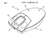
図1は本発明の第1の実施形態による座標入力装置10の分解図、図2は座標入力装置10の組立図、図3は座標入力装置10の筐体の一部切欠図である。座標入力装置10は、パーソナルコンピュータやワークステーション等のデジタルデータ処理装置に電気的又は光学的に接続して、操作者の手持移動操作に伴うアナログ的な情報入力により、ディスプレイ画面上のカーソル移動データ等の座標データを指示する座標入力装置(一般にマウスと称する)として使用できるものである。
【0015】
座標入力装置10は、掌握部12及び掌握部12の反対側の基部14を有する手持可能な筐体16と、筐体16に収容され、掌握部12に隣接して配置される押下操作部18を有するスイッチ機構と、スイッチ機構から独立して筐体16に収容され、基部14に隣接して配置される検出部20を有する自己移動検出機構と、スイッチ機構及び自己移動検出機構から独立して筐体に収容され、タッチパネル式の入力部22を有する第3の入力機構とを備える。なお、本明細書では便宜的に、操作者の右手による通常操作時の指先側を座標入力装置10の前側、手首側を後側、親指側を左側、小指側を右側とし、前後方向を縦方向、左右方向を横方向として記述する。また、座標入力装置10の掌握部12側を上側、基部14側を下側とし、上下方向を高さ方向として記述する。
【0016】
筐体16の掌握部12は、通常操作時に操作者が掌を載せる領域であって、掌で包み込むように持ち易い卵形の湾曲面部分を有する。また基部14は、通常操作時に座標入力装置10を置く適当な物体表面(すなわち搭載平面)に対向支持される領域であって、筐体16を搭載平面に安定的に載せ得る略平坦面部分を有する。掌握部12と基部14とは、例えば図示のように、互いに別部材として樹脂材料から成形されるとともに互いに組み合わせて筐体16を形成する上殻部材24と下殻部材26とに、それぞれ設けることができる。
【0017】
押下操作部18を有するスイッチ機構は、いわゆる左クリック操作及び右クリック操作を実行するための一対の押ボタン式スイッチ(図示せず)を備え、それらスイッチの各々を互いに独立して開閉動作させる一対の押下部材28が、掌握部12に隣接して筐体16上に設置される。各押下部材28は、通常操作時に操作者が所望の指を載せるべく掌握部12に円滑に連続する卵形の湾曲面部分を有する押下部分28aと、押下部分28aから外方へ直線状に延長される梁部分28bとを有する。それら押下部材28は、例えば図示のように、梁部分28bの先端の取付部分28cで互いに一体的に連結され、好ましくは樹脂材料から一体成形される。各押下部材28は、その押下部分28aを、掌握部12の前方で筐体16の上殻部材24に形成される支持板部分24aの上方に配置するとともに、梁部分28bを掌握部12の下方に延長させて、取付部分28cにて、上殻部材24と下殻部材26との間に延設される支柱26aに取り付けられる。それにより各押下部材28は、梁部分28bを介して片持ち梁式に筐体16に支持され、上殻部分24の支持板部分24a上で高さ方向へ僅かな範囲に渡って変位できる。
【0018】
検出部20を有する自己移動検出機構は、ボール30及び一対の回転検出素子(エンコーダ)32を含む機械式検出構造を備える。検出部20を構成するボール30は、基部14に設けた開口34から一部分を外方に露出させて、下殻部材26に転動自在に受容される。また、一対の回転検出素子32は、それぞれの軸端を互いに90°異なる位置でボール30の表面に当接させて、下殻部材26に回動自在に支持される。自己移動検出機構は、操作者の手持操作による搭載平面上での座標入力装置10の移動方向及び移動距離を、ボール30の転動及びそれに伴う一対の回転検出素子32の回転により検出し、二次元座標系におけるデータ信号として出力する。したがって座標入力装置10は、操作者の手持移動操作により、ディスプレイ画面に表示されるポインタを所望位置に移動させてカーソル移動位置を指示する等の座標指示を、データ処理装置に入力できる。
【0019】
筐体16の上殻部材24と下殻部材26との間には、スイッチ機構の一対の押ボタン式スイッチ(図示せず)、自己移動検出機構の一対の発光/受光素子36、CPU(図示せず)等の電子部品を実装した回路基板38が、固定的に設置される。なお、本発明に係る座標入力装置は、スイッチ機構及び自己移動検出機構の構成を限定するものではなく、例えば検出部に発光素子、受光素子及び両素子間の光学系を用いたそれ自体公知の光学式の自己移動検出機構を採用することもできる。
【0020】
第3の入力機構におけるタッチパネル式の入力部22は、掌握部12に隣接して筐体16の表面に露出配置される摺接操作面40を有する検出部材42と、検出部材42への摺接入力操作に応答して摺接操作面40に振動を生じさせる加振部材44とを備えて構成される。検出部材42は、平面視で略矩形の積層パネル構造を有し、2枚の絶縁基板の表面にそれぞれ導電膜を形成してなる一対のシート状検出素子を、両者の導電膜同士を離間かつ対向させた状態で互いに重ね合わせて構成される。検出部材42は、取付組体46により筐体16に固定的に取り付けられ、筐体16の掌握部12の前方で、スイッチ機構の左右一対の押下部材28の間に設置される。この位置で検出部材42は、一方の検出素子の外面を筐体外面に露出させて配置し、この露出面が、操作者が指先を接触させて摺動させる摺接操作面40として機能する。したがって座標入力装置10では、筐体16の手持移動操作による座標データ指示とは別個の独立した指示として、操作者がタッチパネル式入力部22の摺接操作面40上で指先を二次元的に摺動させることにより、指先の移動方向及び移動距離に対応した指示を、スクロール操作等の目的で入力することができる。
【0021】
図4に示すように、取付組体46は、検出部材42を固定支持する平面視略矩形の固定板48と、固定板48の外縁全体を囲繞する防振材50と、固定板48及び防振材50を受容支持する凹所52を有する取付板54と、取付板54の凹所52に受容支持された防振材50を遮蔽するように取付板54に装着されるカバー枠56とを備える。固定板48は、操作者の指先の操作力に抗して検出部材42を平坦形状に保持し得る剛性を有する平板であり、その表面48aに接着剤等を介して検出部材42が固着される。防振材50は、防振ゴム等の振動減衰能に優れた材料から形成される矩形環状部材であり、検出部材42を固着した固定板48と取付板54の凹所52との間に密に挿入されて、例えば接着剤により固定される。防振材50は、操作者の指先の操作力に抗して固定板48を取付板54上の所定位置に保持し得る硬さを有する一方、検出部材42と筐体16との間に介在して、加振部材44により摺接操作面40に生じる振動の、検出部材42から筐体16への伝播を抑制する振動絶縁部材として機能する。
【0022】
取付板54は、内周に沿って環状の凹所52を設けた平面視略矩形の枠部分54aと、枠部分54aから外方へ直線状に延長される梁部分54bと、梁部分54bの先端に形成される取付部分54cとを有し、好ましくは樹脂材料から一体成形される。取付板54は、その枠部分54aを、筐体上殻部材24の支持板部分24aの上方に配置するとともに、梁部分54bを、掌握部12の下方でスイッチ機構の両押下部材28の梁部分28bの間に延長させて、取付部分54cにて、上殻部材24と下殻部材26との間に延設される支柱26aに取り付けられる(図3)。なお固定板48は、防振材50を介して枠部分54aの凹所52に固定的に受容された状態で、その裏面48bが枠部分54aの内側に露出する(図5参照)。
【0023】
カバー枠56は、防振材50を遮蔽する内向突縁56aを有する平面視略矩形の本体部分56bと、本体部分56bから外方へ延長される取付部分56cとを有し、好ましくは樹脂材料から一体成形される。カバー枠56は、その本体部分56bで、取付板54の枠部分54aを包囲して接着剤等により枠部分54aに固定され、内向突縁56aで防振材50を遮蔽するとともに検出部材42の摺接操作面40を露出させる開口を画定する(図5)。この状態で、カバー枠56の取付部分56cは、取付板54の枠部分54aの下方に突出し、筐体上殻部材24の支持板部分24aに固定的に掛着される。このようにして取付組体46は、両端固定梁構造により筐体16に固定的に支持される。
【0024】
入力部22の加振部材44は、回転駆動軸58に設けた非円筒状外周面60を有する回転体からなる。図示実施形態では加振部材44は、電動機等の回転駆動源62の出力軸(すなわち回転駆動軸)58に固定される歯車状部材からなり、その多数の歯が非円筒状外周面60を構成する。加振部材44は、その非円筒状外周面60を、取付板54の枠部分54aの内側に露出する固定板48の裏面48bに当接させて回転できるように、筐体16内に設置される。したがって加振部材44は、回転駆動源62の作動による回転駆動軸58の回転に伴い、非円筒状外周面60がその複数の突端部位で固定板48の裏面48bに連発的に衝突し、それにより、固定板48に固着した検出部材42を微動的に加振して、摺接操作面40に振動を生じさせる。
【0025】
上記構成において、座標入力装置10の操作者は、通常の座標データ指示操作時には、筐体16の掌握部12に掌を載せて筐体16を握るとともに、その手の所望の指(例えば人差指と中指)をスイッチ機構の両押下部材28に載せた状態で、座標入力装置10を適当な搭載平面上で水平移動させる。また操作者は、この掌握状態で適宜、いずれか一方の押下部材28をそれに載せた指で押下して、クリック操作を行なうことができる。そして、入力部22によりスクロール操作等の補助的指示を行なう際には、この掌握状態のままで、いずれか一方の押下部材28に載せた指を検出部材42の摺接操作面40上に移動させて、検出部材42に対し摺接入力操作を行なうことができる。
【0026】
ここで、座標入力装置10が接続されるデータ処理装置の処理部(図示せず)は、入力部22の検出部材42が発する入力信号を適正に受信したときに、加振部材44を回転駆動するための駆動信号を、回転駆動源62に遅滞無く出力するように構成される。そのようなソフト構成を採用することにより、座標入力装置10の操作者は、入力部22の検出部材42に摺接入力操作を行なったときに、その操作の適否(すなわち正確に操作したか否か)を、加振部材44の回転に伴い摺接操作面40に生じる振動をフィードバック信号として指先で触感することによって、即座に確認することができる。特に、処理及び実行に時間を要する指令に関する摺接入力操作を行なった場合であっても、データ処理装置の指令実行を待たずに、摺接入力操作の適否をその操作と略同時に確認できる。したがって座標入力装置10によれば、第3の入力機構により補助的指示を行なう際の、操作者の精神的負担及びそれに伴う疲労を効果的に軽減することができる。
【0027】
また、上記構成を有する座標入力装置10では、入力部22の加振部材44が、その非円筒状外周面60の複数の突端部位で、検出部材42を支持する固定板48の裏面48bに連発的に衝突することにより、検出部材42を微動的に加振して摺接操作面40に振動を生じさせる構成としたから、ソレノイドコイル付きの可動要素によりスイッチ押下部材を殴打する従来の加振手段に比べて、比較的緩やかに継続する振動を検出部材42に印加することができる。したがって座標入力装置10においては、加振部材44の加振作用により検出部材42の高感度の入力検出機能が影響を受けることは未然に回避される。
【0028】
なお、加振部材44は、図示の歯車状部材に限定されず、検出部材42を微動的に加振して摺接操作面40に比較的緩やかな振動を継続して生じさせることを前提に、例えば多角板、楕円板等の、種々の非円筒状部材を採用することができる。
【0029】
さらに座標入力装置10では、入力部22の検出部材42を支持する固定板48と、入力部22を筐体16に固定的に設置するための取付板54との間に、振動絶縁機能を有する防振材50を介在させたから、検出部材42に印加された振動が検出部材42から取付板54を介して筐体16へ伝播することが効果的に防止される。その結果、検出部材42の摺接操作面40に生じる振動は、検出部材42を実際に摺接操作した指先に集中して感受されるので、微動的な振動であっても操作者に明確に識別されるようになる。
【0030】
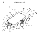
上記した座標入力装置10における入力部22の加振部材44は、その非円筒状外周面60により、摺接入力操作時の摺接操作面40に対する指先の移動方向に関わらず、筐体高さ方向への振幅を有する振動を摺接操作面40に生じさせる構成となっている。これに対し、図6に第2の実施形態として示すように、加振部材が、検出部材における摺接入力操作方向に実質的に一致する方向への振幅を有する振動を、摺接操作面に生じさせる構成を有した入力部を採用することもできる。なお図6は、本発明の第2の実施形態による座標入力装置の入力部22の構成を、図4に示すカバー枠56を取り外した状態で示す図であって、前述した第1の実施形態の構成要素と対応する構成要素には共通の符号を付してその説明を省略する。
【0031】
詳述すれば、図6の実施形態では、取付板54の枠部分54a及びその凹所52に受容される防振材50の各々には、互いに隣接かつ交差する二縁の略中央にそれぞれ切欠部分64、66が形成され、それによりそれら二組の切欠部分64、66において、検出部材42を固定支持した固定板48の外縁が局部的に露出されている。そして、2個の加振部材44が、各々の非円筒状外周面60を切欠部分64、66内の固定板48の露出外縁部分に当接させて回転できるように、二組の切欠部分64、66にそれぞれ受容されて設置される。
【0032】
他方、座標入力装置を接続するデータ処理装置の処理部(図示せず)は、検出部材42が発する入力信号を適正に受信したときに、摺接操作面40に沿った指先の移動方向の縦方向成分と横方向成分とに対応して、2個の加振部材44を回転駆動するための駆動信号を、それぞれの回転駆動源62に遅滞無く出力するように構成される。このような構成により、操作者が検出部材42を入力操作したときに、その摺接入力操作方向に対応していずれか一方の回転駆動源62が作動し、それに伴いいずれか一方の加振部材44が回転して、その非円筒状外周面60で固定板48の一方の露出外縁部分に連発的に衝突することになる。つまり、操作者が指先を摺接操作面40上で筐体縦方向へ摺動させたときには、取付板54の枠部分54aの先端側に設置された加振部材441が回転して、固定板48に固着した検出部材42に、縦方向への振幅を有する振動を印加する。また、操作者が指先を摺接操作面40上で筐体横方向へ摺動させたときには、取付板54の枠部分54aの横側に設置された加振部材442が回転して、固定板48に固着した検出部材42に、横方向への振幅を有する振動を印加する。
【0033】
上記構成を有する入力部22によれば、操作者が検出部材42に摺接入力操作を行なったときに、検出部材42の摺接操作面40には、摺接入力操作方向に実質的に一致する方向への振幅を有する振動が微動的に生じることになる。その結果、操作者は、入力部22における二次元的入力操作方向に対応して、当該方向への入力操作が正確に為されたか否かを、摺接操作面40に生じる振動の方向を指先で触感することによって、即座に確認することができる。
【0034】
図7及び図8は、本発明の第3の実施形態による座標入力装置の入力部22の構成を、検出部材を支持する固定板48の裏面48b側から示す概略図であって、前述した第1の実施形態の構成要素と対応する構成要素には共通の符号を付してその説明を省略する。この実施形態では、検出部材42(図1)への摺接入力操作に応答して摺接操作面40(図1)に振動を生じさせる加振部材として、回転駆動軸68に設けた偏心外周面70を有する回転体からなる加振部材72が用いられている。図示実施形態では加振部材72は、電動機等の回転駆動源(図示せず)の出力軸(すなわち回転駆動軸)68に僅かに偏心して固定される円板状部材からなり、その円筒状外周面が偏心外周面70を構成する。
【0035】
これに対し、固定板48の裏面48bには、その略中央に、円筒状の規制壁74が立設される。加振部材72は、偏心外周面70を規制壁74の内周面に当接させて回転できるように、規制壁74の内側に回動自在に受容されて設置される。したがって加振部材72は、回転駆動源の作動による回転駆動軸68の回転に伴い、偏心外周面70が固定板48の規制壁74に周方向へ連続的に移動する押圧力を加え、それにより、固定板48に固着した検出部材42(図1)を、摺接操作面40に略平行な方向へ微動的に加振して、摺接操作面40に比較的緩やかに継続する振動を生じさせる。
【0036】
上記構成を有する加振部材72によっても、前述した第1実施形態による座標入力装置10の入力部22と同等の作用効果が奏されることは理解されよう。特に、偏心外周面70を有する加振部材72は、固定板48に規制壁74を作製する必要がある反面、前述した非円筒状外周面60を有する加振部材44に比べ、衝突音を生じ難い利点がある。なお、第1及び第2実施形態において、偏心外周面70を有する加振部材72を、非円筒状外周面60を有する加振部材44の代わりに使用することもできる。
【0037】
図9は、本発明の第4の実施形態による座標入力装置の入力部22の構成を、示す分解図であって、前述した第1の実施形態の構成要素と対応する構成要素には共通の符号を付してその説明を省略する。この実施形態では、第1の実施形態における矩形環状の防振材50に替えて、互いに独立した4個の防振材76を採用している。各防振材76は、板ばね等の振動減衰能に優れたばね材から形成され、検出部材42を固着した固定板48の四縁の各々と取付板54の凹所52との間に密に嵌入されて固定される。このような構成を有する防振材76も、第1の実施形態における防振材50と同等の振動絶縁機能を発揮でき、以って、この実施形態の入力部22が、第1の実施形態における入力部22と同等の作用効果を奏することは理解されよう。
【0038】
【発明の効果】
以上の説明から明らかなように、本発明によれば、タッチパネル式の入力部を補助入力機構に有する座標入力装置において、操作者が入力部を正確に摺接入力操作したか否かを、データ処理装置の指令実行を待たずに確認することが可能になり、その結果、補助入力機構を操作する際の操作者の精神的負担が著しく軽減される。また、筐体と検出部材との間に振動絶縁部材を介在させた本発明によれば、入力部の入力検出機能に影響を及ぼすことなく、操作者に識別し易い触感的信号を入力部にフィードバックできるようになる。
【図面の簡単な説明】
【図1】本発明の第1実施形態による座標入力装置の分解斜視図である。
【図2】図1の座標入力装置の組立斜視図である。
【図3】図1の座標入力装置の筐体構造を示す一部切欠斜視図であって、内部構造を省略した図である。
【図4】図1の座標入力装置における第3入力機構の入力部の構成を示す分解斜視図である。
【図5】図4の入力部を組立状態で示す縦断面図である。
【図6】本発明の第2実施形態による座標入力装置における第3入力機構の入力部の構成を示す斜視図である。
【図7】本発明の第3実施形態による座標入力装置における第3入力機構の入力部の構成を概略で示す分解斜視図である。
【図8】図7の入力部を組立状態で示す概略斜視図である。
【図9】本発明の第4実施形態による座標入力装置における第3入力機構の入力部の構成を示す分解斜視図である。
【符号の説明】
12…掌握部
16…筐体
18…押下操作部
20…検出部
22…入力部
40…摺接操作面
42…検出部材
44、72…加振部材
46…取付組体
48…固定板
50、76…防振材
52…凹所
54…取付板
56…カバー枠
58、68…回転駆動軸
60…非円筒状外周面
62…回転駆動源
64、66…切欠部分
70…偏心外周面
74…規制壁[0001]
TECHNICAL FIELD OF THE INVENTION
The present invention relates to an input device used in connection with a data processing device, and more particularly to a coordinate input device for instructing coordinate data on a display screen by an operator's hand-moving operation.
[0002]
[Prior art]
In the field of an input device used by connecting to a digital data processing device such as a personal computer or a workstation, coordinate data such as cursor movement data on a display screen is input by analog information input accompanying an operator's hand-held movement operation. (In general), various auxiliary functions tend to be added in accordance with the development of software on the data processing device side. For example, in a coordinate input device of this type, in addition to a self-movement detection mechanism (ball type, optical type, etc.) for indicating coordinate data, a switch mechanism for push button operation (so-called click operation), Devices having a third (or auxiliary) input mechanism for performing other operations such as a display moving operation (so-called scroll operation) are well known.
[0003]
2. Description of the Related Art Conventionally, as an auxiliary input mechanism of a coordinate input device, there has been proposed a coordinate input device including a touch panel type input unit in which an operator performs an input operation by sliding a fingertip on an operation surface (for example, see Patent Document 1). The touch panel type input unit is configured by stacking a pair of sheet-shaped detection elements each formed by forming a conductive film on the surface of two insulating substrates, with the two conductive films separated and opposed to each other. Having a laminated panel type detecting member. The detection member is disposed adjacent to a grip portion on the upper surface side of the housing of the coordinate input device on which the operator places the palm, and between the pressing members of the pair of left and right switch mechanisms. In this position, the detection member is disposed such that the outer surface of one of the detection elements is exposed to the outer surface of the housing, and the exposed surface is an operation surface (the sliding contact operation in this specification) in which the operator makes a fingertip contact and slides. Function). Therefore, in this coordinate input device, the operator can slide the fingertip two-dimensionally on the sliding operation surface of the touch panel input unit as an independent instruction separate from the coordinate data instruction by the hand-held movement operation of the housing. Accordingly, an instruction corresponding to the moving direction and the moving distance of the fingertip can be input for the purpose of a scroll operation or the like.
[Patent Document 1]
JP-A-11-345082
[0004]
By the way, in the conventional general coordinate input device, the result of the instruction of the coordinate data by the self-movement detecting mechanism can be immediately and visually confirmed as a moving operation of a display such as a pointer on the display screen of the data processing device. Depending on the content of the instruction, the result of the operation instruction consumes time in the processing and execution of the data processing device, so that the appropriateness of the operation may not be immediately confirmed. Therefore, in order to be able to confirm whether or not the operator has correctly operated the switch mechanism without waiting for the execution of the command of the data processing device, a vibration occurs in the switch pressing member when the switch mechanism is clicked. There has been proposed a coordinate input device (see, for example, Patent Document 2). In this coordinate input device, the movable element having the solenoid coil beats the switch pressing member in response to the click operation, thereby vibrating the switch pressing member.
[Patent Document 2]
JP-A-6-43742
[0005]
[Problems to be solved by the invention]
In the conventional coordinate input device having the above-mentioned touch panel type input unit in the auxiliary input mechanism, the operator can input a two-dimensional instruction by sliding the fingertip in a desired direction along the sliding contact operation surface. As compared with other known auxiliary input mechanisms using a one-dimensional input operation member, there is an advantage that the data processing device can execute a wider variety of commands. For example, in the case of a scroll operation, an instruction to move a specific display on the display screen in a direction other than the vertical direction is given by the operator by sliding the fingertip on the sliding contact operation surface in a direction corresponding to the movement command direction of the screen display. Thus, it is possible to input smoothly. At this time, the operator can immediately visually confirm the instruction result of the sliding contact input operation as a display scroll operation on the display screen.
[0006]
However, if such a sliding contact input operation is related to a command that requires time for processing and execution of the data processing device, the operator cannot immediately confirm whether the operation is appropriate. In this case, there is a risk that the operator may mistakenly recognize the elapse of the time leading to the execution of the command as an input operation error and perform unnecessary input operations repeatedly. Conversely, even if the moving direction of the fingertip with respect to the sliding contact operation surface at the time of input deviates from the direction intended by the operator, a result that the required command is not properly executed without confirming the direction may be caused. is there. It is feared that such a malfunction in the input operation increases the mental burden on the operator and the accompanying fatigue.
[0007]
On the other hand, in the conventional coordinate input device having the above-described vibrating means of the switch pressing member in the switch mechanism, the movable element with the solenoid coil hits the switch pressing member which does not have the input detection function itself. When this vibrating means is applied to the above-mentioned touch panel type input unit, there is a concern that the impact at the time of vibrating may adversely affect the high sensitivity input detecting function of the laminated panel type detecting member. In addition, since the applied vibration is easily propagated from the switch pressing member to the input device housing, the vibration may be sensed in the entire hand of the operator, and as a result, the discrimination of the vibration may be weakened.
[0008]
Therefore, an object of the present invention is to provide a coordinate input device having a touch panel type input unit in an auxiliary input mechanism, without waiting for execution of a command of a data processing device, whether or not an operator has performed an accurate sliding contact input operation on an input unit. It is an object of the present invention to provide a coordinate input device capable of confirming the above and thereby reducing the mental burden on the operator.
Another object of the present invention is to provide, in a coordinate input device having a touch panel type input unit in an auxiliary input mechanism, a tactile signal which can be easily identified by an operator without affecting an input detection function of the input unit. An object of the present invention is to provide a coordinate input device that can provide feedback.
[0009]
[Means for Solving the Problems]
In order to achieve the above object, an invention according to claim 1 is a coordinate system comprising: a hand-held housing having a handgrip; and a touch-panel-type input unit installed on the housing adjacent to the handgrip. In the input device, the input unit includes a detection member having a sliding contact operation surface exposed on the surface of the housing, and an excitation that generates vibration on the sliding contact operation surface in response to a sliding contact input operation to the detection member. A coordinate input device comprising:
[0010]
According to a second aspect of the present invention, in the coordinate input device according to the first aspect, the input unit is disposed between the housing and the detection member, and detects the vibration generated on the sliding operation surface by the vibration member. Provided is a coordinate input device that further includes a vibration insulating member that suppresses propagation from a member to a housing.
[0011]
According to a third aspect of the present invention, in the coordinate input device according to the second aspect, the vibration member slides vibration having an amplitude in a direction substantially coinciding with the sliding contact input operation direction of the detecting member. Provided is a coordinate input device to be generated on an operation surface.
[0012]
According to a fourth aspect of the present invention, in the coordinate input device according to any one of the first to third aspects, the vibrating member has a non-cylindrical outer peripheral surface provided on the rotary drive shaft. Provided is a coordinate input device in which a non-cylindrical outer peripheral surface vibrates a detection member with the rotation of.
[0013]
According to a fifth aspect of the present invention, in the coordinate input device according to any one of the first to fifth aspects, the vibrating member has an eccentric outer peripheral surface provided on the rotary drive shaft, and the rotation of the rotary drive shaft Accordingly, there is provided a coordinate input device in which the eccentric outer peripheral surface vibrates the detection member.
[0014]
BEST MODE FOR CARRYING OUT THE INVENTION
Hereinafter, embodiments of the present invention will be described in detail with reference to the accompanying drawings. Corresponding components are denoted by the same reference symbols throughout the drawings.
FIG. 1 is an exploded view of a coordinate
[0015]
The coordinate
[0016]
The
[0017]
The switch mechanism having the
[0018]
The self-movement detection mechanism having the
[0019]
Between the
[0020]
The touch panel-
[0021]
As shown in FIG. 4, the mounting
[0022]
The mounting
[0023]
The
[0024]
The vibrating
[0025]
In the above configuration, the operator of the coordinate
[0026]
Here, a processing unit (not shown) of the data processing device to which the coordinate
[0027]
In the coordinate
[0028]
Note that the
[0029]
Further, the coordinate
[0030]
The vibrating
[0031]
More specifically, in the embodiment of FIG. 6, each of the
[0032]
On the other hand, when the processing unit (not shown) of the data processing device to which the coordinate input device is connected properly receives the input signal generated by the
[0033]
According to the
[0034]
FIGS. 7 and 8 are schematic diagrams showing the configuration of the
[0035]
On the other hand, on the
[0036]
It will be understood that the
[0037]
FIG. 9 is an exploded view showing the configuration of the
[0038]
【The invention's effect】
As is clear from the above description, according to the present invention, in a coordinate input device having a touch panel type input unit in an auxiliary input mechanism, it is determined whether or not the operator has performed an accurate sliding contact input operation on the input unit. The confirmation can be performed without waiting for the execution of the instruction of the processing device, and as a result, the mental burden on the operator when operating the auxiliary input mechanism is significantly reduced. Further, according to the present invention in which the vibration insulating member is interposed between the housing and the detection member, a tactile signal that can be easily identified by the operator is input to the input unit without affecting the input detection function of the input unit. Be able to give feedback.
[Brief description of the drawings]
FIG. 1 is an exploded perspective view of a coordinate input device according to a first embodiment of the present invention.
FIG. 2 is an assembled perspective view of the coordinate input device of FIG. 1;
FIG. 3 is a partially cutaway perspective view showing a housing structure of the coordinate input device of FIG. 1, in which an internal structure is omitted.
FIG. 4 is an exploded perspective view showing a configuration of an input unit of a third input mechanism in the coordinate input device of FIG.
5 is a longitudinal sectional view showing the input unit of FIG. 4 in an assembled state.
FIG. 6 is a perspective view showing a configuration of an input unit of a third input mechanism in a coordinate input device according to a second embodiment of the present invention.
FIG. 7 is an exploded perspective view schematically showing a configuration of an input unit of a third input mechanism in a coordinate input device according to a third embodiment of the present invention.
8 is a schematic perspective view showing the input unit of FIG. 7 in an assembled state.
FIG. 9 is an exploded perspective view showing a configuration of an input unit of a third input mechanism in a coordinate input device according to a fourth embodiment of the present invention.
[Explanation of symbols]
12 ... Grip part
16 ... housing
18 Press operation section
20 Detector
22 Input unit
40 ... Sliding operation surface
42 ... Detection member
44, 72: vibration member
46 ... Mounting assembly
48… Fixed plate
50, 76: anti-vibration material
52 ... recess
54 ... Mounting plate
56 ... Cover frame
58, 68 ... rotary drive shaft
60: Non-cylindrical outer peripheral surface
62 ... Rotary drive source
64, 66 ... notch
70 ... eccentric outer peripheral surface
74 ... Regulatory wall
Claims (5)
前記入力部は、前記筐体の表面に露出配置される摺接操作面を有する検出部材と、該検出部材への摺接入力操作に応答して該摺接操作面に振動を生じさせる加振部材とを具備することを特徴とする座標入力装置。In a coordinate input device including a hand-held housing having a grip portion, and a touch-panel input unit installed in the housing adjacent to the grip portion,
The input unit includes a detection member having a sliding operation surface exposed on a surface of the housing, and an excitation unit that generates vibration on the sliding operation surface in response to a sliding operation input operation on the detection member. A coordinate input device comprising a member.
Priority Applications (1)
| Application Number | Priority Date | Filing Date | Title |
|---|---|---|---|
| JP2003099352A JP4510398B2 (en) | 2003-04-02 | 2003-04-02 | Coordinate input device |
Applications Claiming Priority (1)
| Application Number | Priority Date | Filing Date | Title |
|---|---|---|---|
| JP2003099352A JP4510398B2 (en) | 2003-04-02 | 2003-04-02 | Coordinate input device |
Publications (2)
| Publication Number | Publication Date |
|---|---|
| JP2004310196A true JP2004310196A (en) | 2004-11-04 |
| JP4510398B2 JP4510398B2 (en) | 2010-07-21 |
Family
ID=33463842
Family Applications (1)
| Application Number | Title | Priority Date | Filing Date |
|---|---|---|---|
| JP2003099352A Expired - Fee Related JP4510398B2 (en) | 2003-04-02 | 2003-04-02 | Coordinate input device |
Country Status (1)
| Country | Link |
|---|---|
| JP (1) | JP4510398B2 (en) |
Cited By (3)
| Publication number | Priority date | Publication date | Assignee | Title |
|---|---|---|---|---|
| JP2011501902A (en) * | 2007-10-01 | 2011-01-13 | イマージョン コーポレーション | Directional haptic effects for portable devices |
| JP2014525044A (en) * | 2011-07-25 | 2014-09-25 | シー アンド ジエイ クラーク インターナシヨナル リミテツド | Foot length measuring instrument |
| JP2014199671A (en) * | 2008-03-12 | 2014-10-23 | イマージョン コーポレーションImmersion Corporation | Haptically enabled user interface |
Citations (4)
| Publication number | Priority date | Publication date | Assignee | Title |
|---|---|---|---|---|
| JP2000330688A (en) * | 1999-03-17 | 2000-11-30 | Fuji Xerox Co Ltd | Information sensing device, information transmitting system and storage medium for storing program for controlling the device |
| JP2001290572A (en) * | 2000-04-05 | 2001-10-19 | Fuji Xerox Co Ltd | Information processor |
| JP2001296949A (en) * | 2000-04-14 | 2001-10-26 | Fuji Xerox Co Ltd | Tactile force presenting device and recording medium |
| JP2002149312A (en) * | 2000-08-08 | 2002-05-24 | Ntt Docomo Inc | Portable electronic equipment, electronic equipment, oscillation generator, reporting method by oscillation, and report control method |
-
2003
- 2003-04-02 JP JP2003099352A patent/JP4510398B2/en not_active Expired - Fee Related
Patent Citations (4)
| Publication number | Priority date | Publication date | Assignee | Title |
|---|---|---|---|---|
| JP2000330688A (en) * | 1999-03-17 | 2000-11-30 | Fuji Xerox Co Ltd | Information sensing device, information transmitting system and storage medium for storing program for controlling the device |
| JP2001290572A (en) * | 2000-04-05 | 2001-10-19 | Fuji Xerox Co Ltd | Information processor |
| JP2001296949A (en) * | 2000-04-14 | 2001-10-26 | Fuji Xerox Co Ltd | Tactile force presenting device and recording medium |
| JP2002149312A (en) * | 2000-08-08 | 2002-05-24 | Ntt Docomo Inc | Portable electronic equipment, electronic equipment, oscillation generator, reporting method by oscillation, and report control method |
Cited By (5)
| Publication number | Priority date | Publication date | Assignee | Title |
|---|---|---|---|---|
| JP2011501902A (en) * | 2007-10-01 | 2011-01-13 | イマージョン コーポレーション | Directional haptic effects for portable devices |
| US8508486B2 (en) | 2007-10-01 | 2013-08-13 | Immersion Corporation | Directional haptic effects for a handheld device |
| JP2014199671A (en) * | 2008-03-12 | 2014-10-23 | イマージョン コーポレーションImmersion Corporation | Haptically enabled user interface |
| JP2014525044A (en) * | 2011-07-25 | 2014-09-25 | シー アンド ジエイ クラーク インターナシヨナル リミテツド | Foot length measuring instrument |
| US9380835B2 (en) | 2011-07-25 | 2016-07-05 | C. & J. Clark International Limited | Footgauge |
Also Published As
| Publication number | Publication date |
|---|---|
| JP4510398B2 (en) | 2010-07-21 |
Similar Documents
| Publication | Publication Date | Title |
|---|---|---|
| JP6576432B2 (en) | Game controller | |
| EP3254737B1 (en) | Game controller | |
| JP4811965B2 (en) | Touch panel holding structure | |
| JP3949912B2 (en) | Portable electronic device, electronic device, vibration generator, notification method by vibration and notification control method | |
| US7616192B2 (en) | Touch device and method for providing tactile feedback | |
| US9052873B2 (en) | Electronic apparatus | |
| US20130321272A1 (en) | Wheel mouse | |
| EP3372288B1 (en) | Game controller | |
| US20120186951A1 (en) | Rotary switch mechanism | |
| JP6971553B2 (en) | Game controller | |
| EP3254739B1 (en) | Game controller | |
| EP2666076A1 (en) | Linear vibrator providing localized and generalized haptic feedback | |
| JP6782567B2 (en) | Game controller | |
| EP3254734B1 (en) | Game controller | |
| CA2782913A1 (en) | Control device for controlling cursor motion of electronic device | |
| US20110037696A1 (en) | Wheel mouse | |
| JP4510398B2 (en) | Coordinate input device | |
| JP2000235822A5 (en) | ||
| JP2000235822A (en) | Multi-directional switch and portable electronic apparatus using the same | |
| TWI329275B (en) | ||
| JP3078485U (en) | Tactile feedback interface device and actuator assembly | |
| JP2004303703A (en) | Multidirectional input device | |
| TWM474184U (en) | Control device | |
| CN115120960A (en) | Input device | |
| JP2003157146A (en) | Input device and electronic equipment having input device |
Legal Events
| Date | Code | Title | Description |
|---|---|---|---|
| A621 | Written request for application examination |
Free format text: JAPANESE INTERMEDIATE CODE: A621 Effective date: 20060314 |
|
| A977 | Report on retrieval |
Free format text: JAPANESE INTERMEDIATE CODE: A971007 Effective date: 20080828 |
|
| A131 | Notification of reasons for refusal |
Free format text: JAPANESE INTERMEDIATE CODE: A131 Effective date: 20080902 |
|
| A521 | Request for written amendment filed |
Free format text: JAPANESE INTERMEDIATE CODE: A523 Effective date: 20081028 |
|
| A02 | Decision of refusal |
Free format text: JAPANESE INTERMEDIATE CODE: A02 Effective date: 20090217 |
|
| A521 | Request for written amendment filed |
Free format text: JAPANESE INTERMEDIATE CODE: A523 Effective date: 20090319 |
|
| A911 | Transfer to examiner for re-examination before appeal (zenchi) |
Free format text: JAPANESE INTERMEDIATE CODE: A911 Effective date: 20090616 |
|
| TRDD | Decision of grant or rejection written | ||
| A01 | Written decision to grant a patent or to grant a registration (utility model) |
Free format text: JAPANESE INTERMEDIATE CODE: A01 Effective date: 20100406 |
|
| A01 | Written decision to grant a patent or to grant a registration (utility model) |
Free format text: JAPANESE INTERMEDIATE CODE: A01 |
|
| A61 | First payment of annual fees (during grant procedure) |
Free format text: JAPANESE INTERMEDIATE CODE: A61 Effective date: 20100430 |
|
| FPAY | Renewal fee payment (event date is renewal date of database) |
Free format text: PAYMENT UNTIL: 20130514 Year of fee payment: 3 |
|
| R150 | Certificate of patent or registration of utility model |
Free format text: JAPANESE INTERMEDIATE CODE: R150 |
|
| FPAY | Renewal fee payment (event date is renewal date of database) |
Free format text: PAYMENT UNTIL: 20140514 Year of fee payment: 4 |
|
| R250 | Receipt of annual fees |
Free format text: JAPANESE INTERMEDIATE CODE: R250 |
|
| R250 | Receipt of annual fees |
Free format text: JAPANESE INTERMEDIATE CODE: R250 |
|
| S531 | Written request for registration of change of domicile |
Free format text: JAPANESE INTERMEDIATE CODE: R313531 |
|
| R350 | Written notification of registration of transfer |
Free format text: JAPANESE INTERMEDIATE CODE: R350 |
|
| R250 | Receipt of annual fees |
Free format text: JAPANESE INTERMEDIATE CODE: R250 |
|
| R250 | Receipt of annual fees |
Free format text: JAPANESE INTERMEDIATE CODE: R250 |
|
| LAPS | Cancellation because of no payment of annual fees |