JP2004309636A - Method of fabricating glass structure - Google Patents
Method of fabricating glass structure Download PDFInfo
- Publication number
- JP2004309636A JP2004309636A JP2003100327A JP2003100327A JP2004309636A JP 2004309636 A JP2004309636 A JP 2004309636A JP 2003100327 A JP2003100327 A JP 2003100327A JP 2003100327 A JP2003100327 A JP 2003100327A JP 2004309636 A JP2004309636 A JP 2004309636A
- Authority
- JP
- Japan
- Prior art keywords
- flat glass
- glass structure
- refractive index
- optical fiber
- substrate
- Prior art date
- Legal status (The legal status is an assumption and is not a legal conclusion. Google has not performed a legal analysis and makes no representation as to the accuracy of the status listed.)
- Withdrawn
Links
Images


Abstract
Description
【0001】
【発明の属する技術分野】
本発明は、光ファイバに代表されるような表面が平坦でないガラス構造物内部にフェムト秒パルスレーザを集光照射して、このフェムト秒パルスレーザの集光点周辺に屈折率上昇領域を形成するガラス構造物の加工方法に関する。以下、このような表面が平坦ではないガラス構造物のことを非平板状ガラス構造物と記述する。
【0002】
【従来の技術】
ガラスの内部にフェムト秒パルスレーザ(以下、単に「レーザ」と略すこともある。)を集光照射すると、その集光点周辺は光誘起屈折率変化を起こして、周囲よりも屈折率の高い領域(屈折率上昇領域)が形成される。これを利用して、例えば、直方体形状のガラス内部に連続的にフェムト秒パルスレーザを集光照射することにより、任意形状の光導波路コアを作製する方法がある(例えば、特許文献1参照。)。
【0003】
上記の方法を応用したものとして、光ファイバのコア内部に、光ファイバの長手方向に沿ってフェムト秒パルスレーザの集光照射を繰り返し、グレーティング付き光ファイバを作製する方法がある(例えば、特許文献2参照。)。この方法では、光ファイバの被覆層を除去してクラッドを露出した後、クラッド側面からコア中心に向けてフェムト秒パルスレーザを集光照射する。
【0004】
【特許文献1】
特開平9−311237号公報
【特許文献2】
特開2000−155225号公報
【0005】
【発明が解決しようとする課題】
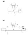
しかしながら、図8(a)に示すように、被覆層2が除去され、光ファイバ素線1のクラッド3が露出された石英系ガラスなどからなる裸光ファイバ4の内部の所望位置に、図示略の光源から発振され、対物レンズ5で集光されたフェムト秒パルスレーザ6を集光照射すると、次のような問題があった。光ファイバ素線1の長手方向と、光ファイバ素線1の長手方向に垂直な方向とでは、表面形状が異なるため、光ファイバ素線1のクラッド3に入射したフェムト秒パルスレーザ6の集光状態は、光ファイバ素線1の長手方向と平行な成分と、光ファイバ素線1の長手方向に垂直な成分とでは異なってしまう。
【0006】
具体的には、図8(b)に示すように、フェムト秒パルスレーザ6の光ファイバ素線1の長手方向に平行な成分(Y成分)は、ガラス平板内部に集光したときとほぼ同じ条件で集光される。一方、図8(c)に示すように、フェムト秒パルスレーザ6の光ファイバ素線1の長手方向に垂直な成分(X成分)は、球面ガラス内部に集光したときとほぼ同じ条件で集光される。ここで、Hは光ファイバ素線1がないと仮定した場合のクラッド3表面からの集光深さ、Hyは光ファイバ素線1の長手方向に平行な成分のクラッド3表面からの集光深さ、Hxは光ファイバ素線1の長手方向に垂直な成分のクラッド3表面からの集光深さを表している。
【0007】
また、図8において、裸光ファイバ4の外径を125μm、クラッド3の屈折率を1.442とし、この裸光ファイバ4に、大気中(屈折率1.0)で開口数0.50の対物レンズ5を用いてフェムト秒パルスレーザを集光照射したとする。図9に、このときの裸光ファイバ4の表面からの集光深さHx(μm)、Hy(μm)を幾何計算から求めた結果と、裸光ファイバ4がないと仮定した場合の裸光ファイバ4の表面からの集光深さH(μm)との関係を示す。図6から、裸光ファイバ4がないと仮定した場合の集光深さHが深くなるほど、直交する2方向の集光深さのずれが大きくなっている。
【0008】
フェムト秒パルスレーザの集光照射を用いた光ファイバ内部への屈折率上昇領域の形成では、レーザの集光点付近におけるエネルギー密度がある閾値を超えたところで、屈折率上昇領域が生じることが知られている。光ファイバ内部に集光照射されたレーザ光の光ファイバの長手方向に平行な成分の集光点と、光ファイバの長手方向に垂直な成分の集光点とが異なると、レーザのエネルギーが分散してしまう。したがって、この方法では、ガラス平板内部に屈折率上昇領域を形成する際に集光照射するレーザと同じ強度のレーザを光ファイバ内部に集光照射しても、屈折率上昇領域を形成するのに必要なエネルギー密度の閾値を超えられない可能性がある。
また、ガラス平板内部に集光照射した場合と同程度の屈折率上昇量を得るために、レーザのエネルギーを大きくする必要が生じると、エネルギー効率が悪い。
【0009】
また、光ファイバの内部にフェムト秒パルスレーザの集光照射によって形成される屈折率上昇領域の形状および屈折率変化量は、このレーザの「平均出力」、「パルス幅」、「繰り返し周波数」、「中心波長」、使用する対物レンズの「開口数」、「倍率」、さらに、集光点を走査する際の「ステージ移動速度」などの多数のパラメータにより決定される。これらのパラメータを最適化することにより、屈折率上昇領域の形状および屈折率変化量を制御することができる。しかしながら、上述のように光ファイバの長手方向に平行な方向と、光ファイバの長手方向に垂直な方向とで集光条件が異なっている場合、他のパラメータをどのように組み合わせても、集光深さを一致させることは根本的に不可能である。
【0010】
本発明は、前記事情に鑑みてなされたもので、光ファイバに代表される非平板状ガラス構造物内部に、フェムト秒パルスレーザを集光照射して、このレーザの集光点周辺に屈折率上昇領域を形成する際に、レーザに垂直な2方向の成分の集光条件の違いを低減し、ガラス平板にレーザを集光照射した場合と近い条件で非平板状ガラス構造物内部にレーザを集光照射するガラス構造物の加工方法を提供することを課題とする。
【0011】
【課題を解決するための手段】
前記課題は、非平板状ガラス構造物にフェムト秒パルスレーザを集光照射し、該非平板状ガラス構造物の内部に屈折率上昇領域を形成するガラス構造物の加工方法において、前記非平板状ガラス構造物を基板上に固定し、該非平板状ガラス構造物の上に該非平板状ガラス構造物の屈折率と等しい屈折率を有する平板ガラスを載置し、前記平板ガラスと、前記非平板状ガラス構造物および前記基板との間に、該非平板状ガラス構造物と屈折率の等しいマッチングオイルを充填して、該非平板状ガラス構造物の内部にフェムト秒パルスレーザを集光照射するガラス構造物の加工方法によって解決できる。
【0012】
また、前記課題は、非平板状ガラス構造物にフェムト秒パルスレーザを集光照射し、該非平板状ガラス構造物の内部に屈折率上昇領域を形成するガラス構造物の加工方法において、前記非平板状ガラス構造物を、温度調整手段を有する基板上に固定し、該非平板状ガラス構造物の上に該非平板状ガラス構造物の屈折率と等しい屈折率を有する平板ガラスを載置し、前記平板ガラスと、前記非平板状ガラス構造物および前記基板との間に、前記非平板状ガラス構造物と室温での屈折率が等しいかもしくは近く、かつ屈折率の温度依存性の絶対値が非平板状ガラス構造物のそれよりも大きいマッチングオイルを充填し、前記温度調整手段によってマッチングオイルの温度を調整することにより、該非平板状ガラス構造物とマッチングオイルとの屈折率を一致させて、該非平板状ガラス構造物の内部にフェムト秒パルスレーザを集光照射するガラス構造物の加工方法によっても解決できる。
この場合、前記温度調整手段は、マッチングオイルを加熱するヒーターもしくはマッチングオイルを冷却する冷却手段とすることができる。
【0013】
上記ガラス構造物の加工方法において、前記基板と前記平板ガラスとの間に2箇所以上設けられたスペーサを介して、前記基板上に前記平板ガラスを載置することが好ましい。
前記非平板状ガラス構造物を石英系光ファイバとし、前記平板ガラスおよび前記マッチングオイルの屈折率を、前記石英系光ファイバを構成するクラッドの屈折率と等しくすることが好ましい。
前記基板上にV溝を形成し、前記非平板状ガラス構造物を該V溝に固定することが好ましい。
【0014】
【発明の実施の形態】
以下、本発明を詳しく説明する。
図1は、本発明のガラス構造物の加工方法の第1の実施形態を示す概略構成図で、図1(a)は光ファイバの軸方向と垂直な断面図、図1(b)は側面図である。図1において、図5に示した従来のガラス構造物の加工方法の構成要素と同じ構成要素には同一符号を付して、その説明を省略する。
この実施形態では、非平板状ガラス構造物として光ファイバを例示し、本発明のガラス構造物の加工方法を詳しく説明する。
【0015】
この実施形態のガラス構造物の加工方法では、先ず、光ファイバ素線1の被覆層2の一部を、有機溶剤などを用いて除去し、レーザを照射する裸光ファイバ4(クラッド3)を露出し、露出したクラッド3の表面を公知の方法により洗浄する。
裸光ファイバ4は、光通信用に使用され、フェムト秒パルスレーザを集光照射したとき集光点で屈折率を増加させるガラスファイバであれば、特に制限されるものではない。裸光ファイバ4の材料としては、例えば、石英系ガラス、酸化物ガラス、フッ化物ガラスが挙げられる。石英系ガラスとしては、例えば、石英系ガラス、ゲルマニウム(Ge)添加石英ガラス、フッ素添加石英ガラス、ゲルマニウム−フッ素共添加石英ガラスなどが挙げられる。酸化物ガラスとしては、例えば、ケイ酸塩ガラス、ホウ酸塩ガラス、リン酸塩ガラス、弗リン酸塩ガラス、酸化ビスマス系ガラスなどが挙げられる。これらの中でも、裸光ファイバ4としては、低損失で、量産性、生産性の高い製造方法が確立されており、コア(図示略)およびクラッド3が石英系ガラスからなる石英系光ファイバを用いることが好ましい。
【0016】
次いで、光ファイバ素線1の裸光ファイバ4を基板11の上に固定する。裸光ファイバ4を基板11の上に固定する方法としては、基板11にV溝を作製し、そのV溝に沿って配置させる方法が挙げられる。
基板11は、石英ガラス基板であることが望ましいが、その表面に裸光ファイバ4を保持、固定するための平坦面を有するものであれば特に限定されない。また、基板11の厚みも適宜設定される。
【0017】
次いで、裸光ファイバ4の上に、任意の厚みの平板ガラス12を載せる。
平板ガラス12は、両面とも鏡面研磨されたガラス平板であり、裸光ファイバ4を構成するクラッド3の屈折率と等しいか、それに十分近い屈折率を有するものである。
また、平板ガラス12の厚みは適宜設定されるが、この厚みを適切に選択することにより、ガラス平板の内部の所望深さにフェムト秒パルスレーザを集光照射した場合と近い条件で、裸光ファイバ4の内部の所望深さにフェムト秒パルスレーザを集光照射することもできる。
【0018】
次いで、平板ガラス12と、裸光ファイバ4および基板11との間に、裸光ファイバ4を形成する材料(例えば、石英系ガラス)の屈折率と等しい屈折率を有するマッチングオイル13を充填する。このとき、平板ガラス12と裸光ファイバ4、および基板11と裸光ファイバ4とはマッチングオイル13を介して積層されている。
マッチングオイル13は、裸光ファイバ4を形成する材料の屈折率と等しい屈折率を有するものであれば特に限定されないが、裸光ファイバ4を構成するクラッド3の屈折率と等しい屈折率を有するものが好ましい。また、マッチングオイル13は、平板ガラス12と、裸光ファイバ4および基板11との間から流出するのを防ぐために、ゲル状であることが好ましい。
【0019】
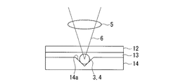
次いで、この状態で平板ガラス12の鉛直上方から、図示略の光源から発振され、対物レンズ5で集光されたフェムト秒パルスレーザ6を、裸光ファイバ4の内部の所望位置(所望の深さ)に集光照射し、裸光ファイバ4の内部に光誘起屈折率変化を起こして、周囲よりも屈折率の高い屈折率上昇領域を形成する。
このとき、フェムト秒パルスレーザ6の波長を、例えば750nm〜850nmの近赤外領域とすることが望ましい。また、フェムト秒パルスレーザ6の繰り返し周波数は、特に限定されるものではないが、10kHz以上が望ましい。
【0020】
ここで、フェムト秒パルスレーザとは、パルス幅が1ps以下のレーザのことである。このように、フェムト秒パルスレーザのパルス幅は非常に狭いので、フェムト秒パルスレーザのピークパワーは時間圧縮効果により増大し、さらにこのようなレーザを対物レンズで集光することから、光誘起屈折率変化を起こすことができる。
【0021】
この実施形態では、平板ガラス12と、裸光ファイバ4および基板11との間に、裸光ファイバ4を形成する材料と屈折率の等しいマッチングオイル13を充填して、裸光ファイバ4の内部の所望位置にフェムト秒パルスレーザ6を集光照射するから、平板ガラス12を通過したフェムト秒パルスレーザ6が、裸光ファイバ4に入射する際に屈折されることがない。すなわち、この実施形態によれば、裸光ファイバ4の形状に影響されることなく、裸光ファイバ4の内部の所望位置にフェムト秒パルスレーザ6を集光照射することができる。したがって、フェムト秒パルスレーザ6の光ファイバ素線1の長手方向に平行な成分の集光点の位置と、フェムト秒パルスレーザ6の光ファイバ素線1の長手方向に垂直な成分の集光点の位置とをほぼ同じにすることができる。
【0022】
また、この実施形態では、平板ガラス12およびマッチングオイル13を、石英系光ファイバの裸光ファイバ4を構成するクラッド3の屈折率と等しい屈折率を有するものとするから、平板ガラス12、マッチングオイル13、クラッド3の順に通過したフェムト秒パルスレーザ6が、裸光ファイバ4の内部に到達するまで屈折されることがない。すなわち、この実施形態によれば、裸光ファイバ4の形状に影響されることなく、裸光ファイバ4の内部の所望位置に、より高精度にフェムト秒パルスレーザ6を集光照射することができる。
【0023】
図2は、本発明のガラス構造物の加工方法の第2の実施形態を示す概略断面図である。
この実施形態のガラス構造物の加工方法において、上述の第1の実施形態と異なる点は、裸光ファイバ4を基板14の上に固定する際に、裸光ファイバ4を基板14の表面に形成されたV溝14aに固定する点である。裸光ファイバ4をV溝14aに固定するには、V溝14aを、裸光ファイバ4の外径に応じて所定の開口大きさ、側壁の角度に加工し、このV溝14a内に裸光ファイバ4を載置する。また、裸光ファイバ4のV溝14a内における回転を防止するために、光ファイバ素線1の裸光ファイバ4以外の部分、すなわち、裸光ファイバ4の両端側の被覆部分をクランプなどで保持してもよい。
この実施形態では、基板14は、上述の基板11と同様に石英ガラス基板であることが望ましい。基板14の厚みは、所望の大きさ(深さ)のV溝14aを形成することができる程度に適宜設定される。
【0024】
この実施形態によれば、裸光ファイバ4をV溝14aに固定することにより、基板14上において、裸光ファイバ4が移動、回転するのを防止することができるから、裸光ファイバ4の内部の所望位置に、より高精度にフェムト秒パルスレーザ6を集光照射することができる。
【0025】
なお、第1および第2の実施形態では、非平板状ガラス構造物として裸光ファイバ4を例示したが、第1および第2の実施形態は、非平板状ガラス構造物が、後述のような表面が曲面形状のガラス基板であっても適用可能である。
【0026】
図3は、本発明のガラス構造物の加工方法の第3の実施形態を示す概略断面図である。
この実施形態では、非平板状ガラス構造物として表面が曲面形状のガラス基板20を例示する。
この実施形態のガラス構造物の加工方法において、上述の第1の実施形態と異なる点は、基板11と平板ガラス12との間に2箇所以上設けられた厚みの等しいスペーサ15を介して、基板11上に平板ガラス12を載置する点である。この時、少なくとも2個のスペーサ15によって、ガラス基板20を、その長手方向あるいは短手方向の両側から挟むように、スペーサ15を基板11上に配置する。さらに、スペーサ15の厚みを、ガラス基板20の厚みの最も大きい部分以上とする。
スペーサ15は、基板11および平板ガラス12と接触する面が平滑面である平板であれば特に限定されないが、少量のマッチングオイルなどにより平板ガラス12および基板11と密着するものが望ましい。
【0027】
この実施形態によれば、ガラス基板20の表面形状がいかなるものであっても、基板11と平板ガラス12とを平行に配置し、この状態を維持することができる。したがって、平板ガラス12が傾くことにより生じるフェムト秒パルスレーザ6の屈折が生じることがなく、ガラス基板20の内部の所望位置に、より高精度にフェムト秒パルスレーザ6を集光照射することができる。
【0028】
なお、この実施形態では、非平板状ガラス構造物として表面が曲面形状のガラス基板20を例示したが、この実施形態は、非平板状ガラス構造物が、上述のような裸光ファイバ4であっても適用可能である。
【0029】
図4は、本発明のガラス構造物の加工方法の第4の実施形態を示す概略断面図である。
この実施形態のガラス構造物の加工方法において、上述の第1の実施形態と異なる点は、基板30が温度調整手段32を有している点である。すなわち、この基板30は、基板本体31と、該基板本体31の上部に取り付けられたヒーター33と、ヒーター33の温度を制御する温度制御部34とを備えている。上記温度調整手段32は、ヒーター33と温度制御部34とにより構成されている。
この実施形態では、基板本体31は、上述の基板11と同様に石英ガラス基板であることが望ましい。
【0030】
ヒーター33としては、例えば電熱により発熱する公知のヒータが例示でき、非平板状ガラス構造物(ここでは裸光ファイバ4)の寸法に応じた適当なものが用いられる。
温度制御部34は、例えばマッチングオイル13の温度を測定して、この温度の測定値に基づいてヒーター33に流す電流量を制御し、ヒーター33により加熱されるマッチングオイル13を所定の温度範囲内に維持する公知の制御用部品である。
【0031】
マッチングオイル13は、室温において非平板状ガラス構造物と屈折率が等しいかもしくは近く、かつ屈折率の温度依存性の絶対値が非平板状ガラス構造物のそれよりも大きいものが用いられる。本発明において、屈折率の温度依存性とは、単位温度あたりの屈折率の変化量を示す。また、室温においてマッチングオイルと非平板状ガラス構造物との屈折率が等しいかもしくは近いとは、該マッチングオイルの温度を、劣化や変質などの不具合が生じない温度範囲内で調整することにより、ある調整された温度において、マッチングオイルと非平板状ガラス構造物の屈折率が一致するようにすることができることをいう。
【0032】
例えば、非平板状ガラス構造物が石英系ガラスの場合、マッチングオイル13としては、室温における屈折率が石英系ガラスの屈折率に近く、また、屈折率の温度依存性の絶対値が大きいシリコーンオイルが好ましい。一般に、シリコーンオイルは、屈折率の温度依存性が負であり、温度が高くなるほど屈折率が低下する。従って、シリコーンオイルを室温よりも高い温度に加熱することによって、該シリコーンオイルの屈折率を非平板状ガラス構造物のそれと一致させるためには、室温での屈折率が、非平板状ガラス構造物の屈折率よりも大きいシリコーンオイルを選定して用いる必要がある。この選定は、公知の種々のシリコーンオイルから、適当な物性を示す組成のものを選択すればよい。
【0033】
この実施形態により裸光ファイバの加工を行うには、上述の実施形態と同様に、基板30上に裸光ファイバ4を固定し、裸光ファイバ4の上に平板ガラス12を載せ、平板ガラス12と、裸光ファイバ4および基板30との間に、上述のマッチングオイル13を充填する。温度調整手段32によりマッチングオイル13を加熱して、マッチングオイル13と裸光ファイバ4との屈折率が一致する温度に維持し、この状態で、フェムト秒パルスレーザ6の集光照射により裸光ファイバ4の加工を行う。
【0034】
本実施の形態によれば、マッチングオイル13を加熱して温度を調整することにより、マッチングオイル13の温度に応じてその屈折率を変化させることができるので、非平板状ガラス構造物のガラス組成などの変動により、該非平板状ガラス構造物の屈折率が変動している場合でも、多種類のマッチングオイル13を用意することなく、マッチングオイル13と裸光ファイバ4との屈折率を一致させた状態で加工することができる。
なお、上記説明では、非平板状ガラス構造物として裸光ファイバ4を例示したが、この実施形態は、非平板状ガラス構造物が、上述のような表面が曲面形状のガラス基板20であっても適用可能である。また、上記基板として、V溝を有するものを用いることも可能である。
【0035】
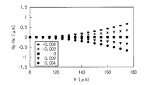
以下、本発明の効果を明らかにするため、図1においてマッチングオイル13の屈折率を変化させた場合の、平板ガラス12の表面からの集光深さHx、Hyの差(=Hy−Hx)を幾何計算し、平板ガラス12と裸光ファイバ4がないと仮定した場合の平板ガラス12の表面からの集光深さHに対してプロットした結果を図5に示す。
ここでは、裸光ファイバ4の外径を125μm、クラッド3、および平板ガラス12の屈折率を1.442、平板ガラスの厚さを100μmとする。また、対物レンズ5の開口数は0.50とする。図中の5種類の点はそれぞれ、マッチングオイル13の屈折率と、クラッド3の屈折率との差を表している。マッチングオイル13の屈折率が、クラッド3および平板ガラス12の屈折率と一致している場合、ガラス平板の内部に集光した場合と同じ条件で裸光ファイバ4の内部に集光したことになるから、平板ガラス12と裸光ファイバ4がないと仮定した場合の集光深さHに関係なく、HyとHxとで集光深さの差はない。
また、マッチングオイル13の屈折率が、クラッド3および平板ガラス12に対して±0.004、すなわち比屈折率差にして約0.27%変動しても、例えばH=140μmとして、ほぼ光ファイバの中心部分に集光した場合の、HyとHxとの差(Hy−Hx)は、0.2μm以下に抑えられている。これにより、従来の方法に比べて、集光深さの差が大幅に改善されることがわかる。
【0036】
次に、マッチングオイルを加熱するヒーターを有する温度調整手段を用いた場合の効果を明らかにするため、図4において、裸光ファイバ4として純粋石英ガラスからなるコアなしの裸光ファイバを用いた。純粋石英ガラスは、25℃における屈折率が1.45847であり、屈折率の温度依存性が+8×10⁻⁶/℃である。
マッチングオイル13として、25℃、波長589.3nmにおける屈折率が1.460であり、屈折率の温度依存性が−4×10⁻⁴/℃である市販のシリコーンオイルを用いた。
図6に、純粋石英ガラスと上記マッチングオイルとの屈折率と温度との関係を示す。両者の屈折率は、温度が29℃の場合に最もよく一致するので、ヒータ−33に流す電流量を調整してマッチングオイル13の温度を29℃に維持して裸光ファイバ4の加工を行ったところ、裸光ファイバ4の所望の深さにフェムト秒パルスレーザを集光照射することができた。
【0037】
次に、マッチングオイル13として、25℃における屈折率が1.470であり、屈折率の温度依存性が−4×10⁻⁴/℃であるシリコーンオイルを、市販のシリコーンオイルを複数種類調合することにより調製して用いた。
図7に、純粋石英ガラスと上記マッチングオイルとの屈折率と温度との関係を示す。両者の屈折率は、温度が52℃の場合に最もよく一致するので、ヒータ−33に流す電流量を調整してマッチングオイル13の温度を52℃に維持して裸光ファイバ4の加工を行ったところ、裸光ファイバ4の所望の深さにフェムト秒パルスレーザを集光照射することができた。
【0038】
次に、裸光ファイバ4としてGe添加石英ガラスからなるコアなしの裸光ファイバを用いた。このGe添加石英ガラスは、25℃における屈折率が1.465であり、屈折率の温度依存性が+8×10⁻⁶/℃である。
マッチングオイル13として、25℃における屈折率が1.470であり、屈折率の温度依存性が−4×10⁻⁴/℃である市販のシリコーンオイルを用いた。
図7に、Ge添加石英ガラスと上記マッチングオイルとの屈折率と温度との関係を示す。両者の屈折率は、温度が36℃の場合に最もよく一致するので、ヒータ−33に流す電流量を調整してマッチングオイル13の温度を36℃に維持して裸光ファイバ4の加工を行ったところ、裸光ファイバ4の所望の深さにフェムト秒パルスレーザを集光照射することができた。
【0039】
【発明の効果】
以上説明したように、本発明のガラス構造物の加工方法は、非平板状ガラス構造物を基板上に固定し、非平板状ガラス構造物の上に非平板状ガラス構造物の屈折率と等しい屈折率を有する平板ガラスを載置し、平板ガラスと、非平板状ガラス構造物および基板との間に、非平板状ガラス構造物と屈折率の等しいマッチングオイルを充填して、非平板状ガラス構造物の内部にフェムト秒パルスレーザを集光照射するから、ガラス平板内部に屈折率上昇領域を形成する際に集光照射されるフェムト秒パルスレーザと同じ強度のフェムト秒パルスレーザを、非平板状のガラス構造物の内部に集光照射することにより、所望の屈折率を示す屈折率上昇領域を形成することができる。
【0040】
ヒーターや冷却手段などの温度調整手段によりマッチングオイルの温度を調整するようにした場合、マッチングオイルの温度に応じてその屈折率を変化させることができるので、非平板状ガラス構造物のガラス組成などの変動により、該非平板状ガラス構造物の屈折率が変動している場合でも、多種類のマッチングオイルを用意することなく、マッチングオイルと非平板状ガラス構造物との屈折率を一致させた状態で加工することができる。
【0041】
また、非平板状ガラス構造物を石英系光ファイバとし、平板ガラスおよびマッチングオイルの屈折率を、石英系光ファイバを構成するクラッドの屈折率と等しくすれば、非平板状ガラス構造物の形状に影響されることなく、非平板状ガラス構造物の内部の所望位置に、より高精度にフェムト秒パルスレーザを集光照射することができる。
さらに、基板上にV溝を形成し、非平板状ガラス構造物をこのV溝に固定すれば、基板上において、非平板状ガラス構造物が移動、回転するのを防止することができるから、非平板状ガラス構造物の内部の所望位置に、より高精度にフェムト秒パルスレーザを集光照射することができる。
そして、基板と平板ガラスとの間に2箇所以上設けられたスペーサを介して、基板上に平板ガラスを載置すれば、平板ガラスが傾くことにより生じるフェムト秒パルスレーザの屈折が生じることがなくなり、非平板状ガラス構造物の内部の所望位置に、より高精度にフェムト秒パルスレーザを集光照射することができる。
【図面の簡単な説明】
【図1】本発明のガラス構造物の加工方法の第1の実施形態を示す概略構成図で、図1(a)は光ファイバの軸方向と垂直な断面図、図1(b)は側面図である。
【図2】本発明のガラス構造物の加工方法の第2の実施形態を示す概略断面図である。
【図3】本発明のガラス構造物の加工方法の第3の実施形態を示す概略断面図である。
【図4】本発明のガラス構造物の加工方法の第4の実施形態を示す概略断面図である。
【図5】マッチングオイルの屈折率と、クラッドおよび平板ガラスの屈折率との差に応じて変化する、光ファイバ素線がないと仮定した場合のクラッド表面からの集光深さHと、Hy−Hxとの関係を示すグラフである。
【図6】純粋石英ガラスおよびマッチングオイルの屈折率と、温度との関係の一例を示すグラフである。
【図7】純粋石英ガラス、Ge添加石英ガラス、およびマッチングオイルの屈折率と、温度との関係の一例を示すグラフである。
【図8】従来の光ファイバの加工方法を示す概略構成図で、図8(a)は斜視図、図8(b)は側面図、図8(c)は光ファイバの軸方向と垂直な断面図である。
【図9】光ファイバの内部の光ファイバ素線がないと仮定した場合のクラッド表面からの集光深さHの点にレーザを集光照射した時の実際の集光深さHy、Hxを示すグラフである。
【符号の説明】
1・・・光ファイバ素線、2・・・被覆層、3・・・クラッド、4・・・裸光ファイバ、5・・・対物レンズ、6・・・フェムト秒パルスレーザ、11,14・・・基板、12・・・平板ガラス、13・・・マッチングオイル、15・・・スペーサ、20・・・ガラス基板、30・・・基板、31・・・温度調整手段、33・・・ヒーター。[0001]
TECHNICAL FIELD OF THE INVENTION
The present invention focuses and irradiates a femtosecond pulse laser inside a glass structure whose surface is not flat as represented by an optical fiber, and forms a refractive index increasing region around a focus point of the femtosecond pulse laser. The present invention relates to a method for processing a glass structure. Hereinafter, such a glass structure whose surface is not flat is described as a non-flat glass structure.
[0002]
[Prior art]
When a femtosecond pulse laser (hereinafter sometimes simply referred to as “laser”) is condensed and radiated inside the glass, a light-induced refractive index change occurs around the focal point, and the refractive index is higher than the surroundings. A region (increased refractive index region) is formed. Utilizing this, for example, there is a method of manufacturing an optical waveguide core having an arbitrary shape by condensing and irradiating a femtosecond pulse laser continuously inside a rectangular parallelepiped glass (for example, see Patent Document 1). .
[0003]
As a method to which the above method is applied, there is a method of manufacturing an optical fiber with a grating by repeatedly focusing and irradiating a femtosecond pulse laser inside a core of the optical fiber along the longitudinal direction of the optical fiber (for example, Patent Document 1). 2). In this method, after the cladding is exposed by removing the coating layer of the optical fiber, a femtosecond pulse laser is focused and irradiated from the side of the cladding toward the center of the core.
[0004]
[Patent Document 1]
JP-A-9-311237
[Patent Document 2]
JP 2000-155225 A
[0005]
[Problems to be solved by the invention]
However, as shown in FIG. 8A, the
[0006]
Specifically, as shown in FIG. 8B, the component (Y component) parallel to the longitudinal direction of the
[0007]
In FIG. 8, the outer diameter of the bare
[0008]
In the formation of a refractive index increasing region inside an optical fiber using focused irradiation of a femtosecond pulse laser, it is known that a refractive index increasing region occurs when the energy density near the laser focusing point exceeds a certain threshold. Have been. If the focal point of the component parallel to the longitudinal direction of the optical fiber is different from the focal point of the component perpendicular to the longitudinal direction of the optical fiber, the laser energy will be dispersed. Resulting in. Therefore, in this method, even when a laser beam having the same intensity as the laser beam used for converging and irradiating the laser beam when forming the refractive index increasing region inside the glass plate is condensed and irradiated inside the optical fiber, the refractive index increasing region is formed. The required energy density threshold may not be exceeded.
Further, if it becomes necessary to increase the energy of the laser in order to obtain the same amount of increase in the refractive index as when converging and irradiating the inside of the glass plate, the energy efficiency is poor.
[0009]
In addition, the shape and the amount of change in the refractive index of the refractive index rising region formed by the focused irradiation of the femtosecond pulse laser inside the optical fiber are the “average output”, “pulse width”, “repetition frequency”, It is determined by a number of parameters such as the "center wavelength", the "numerical aperture" of the objective lens to be used, the "magnification", and the "stage moving speed" when scanning the focal point. By optimizing these parameters, it is possible to control the shape of the refractive index increasing region and the amount of change in the refractive index. However, as described above, if the light collecting conditions are different between the direction parallel to the longitudinal direction of the optical fiber and the direction perpendicular to the longitudinal direction of the optical fiber, the light collecting Matching depth is fundamentally impossible.
[0010]
The present invention has been made in view of the above circumstances, and focuses and irradiates a femtosecond pulse laser on the inside of a non-flat glass structure represented by an optical fiber, thereby forming a refractive index around the focal point of the laser. When forming the ascending region, the difference in the focusing conditions of the components in the two directions perpendicular to the laser is reduced, and the laser is applied to the inside of the non-flat glass structure under conditions similar to those when the laser is focused on a flat glass plate. An object of the present invention is to provide a method for processing a glass structure to be subjected to focused irradiation.
[0011]
[Means for Solving the Problems]
The object is to provide a method of processing a glass structure in which a non-flat glass structure is irradiated with a femtosecond pulse laser to form a refractive index increasing region inside the non-flat glass structure. A structure is fixed on a substrate, and a flat glass having a refractive index equal to the refractive index of the non-flat glass structure is placed on the non-flat glass structure. The flat glass and the non-flat glass Filling a matching oil having a refractive index equal to that of the non-flat glass structure between the structure and the substrate, and condensing and irradiating a femtosecond pulse laser inside the non-flat glass structure. It can be solved by the processing method.
[0012]
Further, the object is to provide a method for processing a glass structure, which comprises irradiating a non-planar glass structure with a femtosecond pulsed laser to form a refractive index increasing region inside the non-flat glass structure. The glass-like glass structure is fixed on a substrate having a temperature adjusting means, and a flat glass having a refractive index equal to that of the non-flat glass structure is placed on the non-flat glass structure. Between the glass and the non-flat glass structure and the substrate, the non-flat glass structure and the refractive index at room temperature are equal to or close to each other, and the absolute value of the temperature dependence of the refractive index is non-flat. By filling a matching oil larger than that of the flat glass structure and adjusting the temperature of the matching oil by the temperature adjusting means, the bending between the non-flat glass structure and the matching oil is reduced. To match the rate, the femtosecond pulsed laser inside the non-flat glass structure can be resolved by the processing method of the glass structure focused irradiation.
In this case, the temperature adjusting means may be a heater for heating the matching oil or a cooling means for cooling the matching oil.
[0013]
In the above method for processing a glass structure, it is preferable that the flat glass be placed on the substrate via spacers provided at two or more locations between the substrate and the flat glass.
It is preferable that the non-flat glass structure is a silica-based optical fiber, and the refractive indexes of the flat glass and the matching oil are equal to the refractive index of a clad constituting the silica-based optical fiber.
Preferably, a V-groove is formed on the substrate, and the non-flat glass structure is fixed to the V-groove.
[0014]
BEST MODE FOR CARRYING OUT THE INVENTION
Hereinafter, the present invention will be described in detail.
FIG. 1 is a schematic configuration diagram showing a first embodiment of a method for processing a glass structure according to the present invention. FIG. 1A is a cross-sectional view perpendicular to the axial direction of an optical fiber, and FIG. FIG. In FIG. 1, the same components as those of the conventional method for processing a glass structure shown in FIG. 5 are denoted by the same reference numerals, and description thereof will be omitted.
In this embodiment, an optical fiber is exemplified as the non-flat glass structure, and the processing method of the glass structure of the present invention will be described in detail.
[0015]
In the method for processing a glass structure according to this embodiment, first, a part of the
The bare
[0016]
Next, the bare
The
[0017]
Next, the
The
The thickness of the
[0018]
Next, a matching
The matching
[0019]
Next, in this state, the
At this time, the wavelength of the
[0020]
Here, the femtosecond pulse laser is a laser having a pulse width of 1 ps or less. As described above, the pulse width of the femtosecond pulse laser is very narrow, and the peak power of the femtosecond pulse laser increases due to the time compression effect. Rate changes can occur.
[0021]
In this embodiment, a matching
[0022]
In this embodiment, the
[0023]
FIG. 2 is a schematic cross-sectional view showing a second embodiment of the method for processing a glass structure according to the present invention.
The method of processing a glass structure according to this embodiment is different from the first embodiment in that the bare
In this embodiment, the
[0024]
According to this embodiment, since the bare
[0025]
In the first and second embodiments, the bare
[0026]
FIG. 3 is a schematic sectional view showing a third embodiment of the method for processing a glass structure according to the present invention.
In this embodiment, a
The method of processing a glass structure according to this embodiment is different from the above-described first embodiment in that a
The
[0027]
According to this embodiment, regardless of the surface shape of the
[0028]
In this embodiment, the
[0029]
FIG. 4 is a schematic sectional view showing a fourth embodiment of the method for processing a glass structure according to the present invention.
In the method for processing a glass structure according to this embodiment, the difference from the first embodiment is that the
In this embodiment, the substrate
[0030]
As the
The
[0031]
As the matching
[0032]
For example, when the non-flat glass structure is quartz glass, the matching
[0033]
In order to process the bare optical fiber according to this embodiment, the bare
[0034]
According to the present embodiment, by adjusting the temperature by heating the matching
In the above description, the bare
[0035]
Hereinafter, in order to clarify the effect of the present invention, the difference between the light condensing depths Hx and Hy from the surface of the
Here, the outer diameter of the bare
Even if the refractive index of the matching
[0036]
Next, in order to clarify the effect when the temperature adjusting means having a heater for heating the matching oil is used, in FIG. 4, a bare optical fiber having no core made of pure silica glass was used as the bare
As the matching
FIG. 6 shows the relationship between the refractive index and the temperature of pure quartz glass and the matching oil. Since the refractive indices of the two agree best when the temperature is 29 ° C., the bare
[0037]
Next, as the matching
FIG. 7 shows the relationship between the refractive index of pure silica glass and the matching oil and the temperature. Since the refractive indices of both match best when the temperature is 52 ° C., the amount of current flowing through the
[0038]
Next, a coreless bare optical fiber made of Ge-doped silica glass was used as the bare
As the matching
FIG. 7 shows the relationship between the refractive index and the temperature of the Ge-doped quartz glass and the matching oil. Since the refractive indices of the two match best when the temperature is 36 ° C., the amount of current flowing through the
[0039]
【The invention's effect】
As described above, the method for processing a glass structure according to the present invention includes fixing the non-flat glass structure on the substrate and setting the refractive index of the non-flat glass structure on the non-flat glass structure equal to the refractive index of the non-flat glass structure. A flat glass having a refractive index is placed, and between the flat glass and the non-flat glass structure and the substrate, a matching oil having the same refractive index as the non-flat glass structure is filled, and the non-flat glass is filled. Since a femtosecond pulse laser is focused and irradiated inside the structure, a femtosecond pulse laser with the same intensity as the femtosecond pulse laser that is focused and irradiated when forming the refractive index rising region inside the glass plate is used as a non-flat plate. By condensing and irradiating the inside of the glass-like structure, it is possible to form a refractive index increasing region having a desired refractive index.
[0040]
If the temperature of the matching oil is adjusted by a temperature adjusting means such as a heater or a cooling means, the refractive index can be changed according to the temperature of the matching oil, so that the glass composition of the non-flat glass structure, etc. Even if the refractive index of the non-flat glass structure fluctuates due to fluctuations in the state, the matching oil and the non-flat glass structure have the same refractive index without preparing various types of matching oils. Can be processed.
[0041]
In addition, if the non-flat glass structure is made of a silica-based optical fiber and the refractive index of the flat glass and the matching oil is made equal to the refractive index of the cladding constituting the silica-based optical fiber, the shape of the non-flat glass structure is obtained. Without being affected, the femtosecond pulse laser can be focused and radiated to a desired position inside the non-flat glass structure with higher accuracy.
Further, if a V-groove is formed on the substrate and the non-flat glass structure is fixed to the V-groove, the non-flat glass structure can be prevented from moving and rotating on the substrate. A femtosecond pulse laser can be condensed and irradiated to a desired position inside the non-flat glass structure with higher accuracy.
Then, if the flat glass is placed on the substrate via the spacer provided at two or more places between the substrate and the flat glass, the refraction of the femtosecond pulse laser caused by the inclination of the flat glass is eliminated. In addition, a femtosecond pulse laser can be condensed and irradiated to a desired position inside the non-flat glass structure with higher accuracy.
[Brief description of the drawings]
FIG. 1 is a schematic configuration diagram illustrating a first embodiment of a method for processing a glass structure according to the present invention. FIG. 1A is a cross-sectional view perpendicular to the axial direction of an optical fiber, and FIG. FIG.
FIG. 2 is a schematic sectional view showing a second embodiment of the method for processing a glass structure according to the present invention.
FIG. 3 is a schematic cross-sectional view showing a third embodiment of the method for processing a glass structure of the present invention.
FIG. 4 is a schematic sectional view showing a fourth embodiment of the method for processing a glass structure according to the present invention.
FIG. 5 is a diagram showing the relationship between the refractive index of the matching oil and the refractive index of the cladding and the flat glass. It is a graph which shows the relationship with -Hx.
FIG. 6 is a graph showing an example of the relationship between the refractive index of pure quartz glass and matching oil and temperature.
FIG. 7 is a graph showing an example of a relationship between refractive index of pure quartz glass, Ge-doped quartz glass, and matching oil, and temperature.
8 (a) is a perspective view, FIG. 8 (b) is a side view, and FIG. 8 (c) is a view perpendicular to the axial direction of the optical fiber. It is sectional drawing.
FIG. 9 shows actual focusing depths Hy and Hx when a laser is focused and irradiated on a point having a focusing depth H from the cladding surface, assuming that there is no optical fiber in the optical fiber. It is a graph shown.
[Explanation of symbols]
DESCRIPTION OF
Claims (7)
前記非平板状ガラス構造物を基板上に固定し、該非平板状ガラス構造物の上に該非平板状ガラス構造物の屈折率と等しい屈折率を有する平板ガラスを載置し、
前記平板ガラスと、前記非平板状ガラス構造物および前記基板との間に、該非平板状ガラス構造物と屈折率の等しいマッチングオイルを充填して、該非平板状ガラス構造物の内部にフェムト秒パルスレーザを集光照射することを特徴とするガラス構造物の加工方法。A femtosecond pulse laser is condensed and irradiated on the non-flat glass structure, and a method for processing a glass structure for forming a refractive index increasing region inside the non-flat glass structure,
The non-flat glass structure is fixed on a substrate, and a flat glass having a refractive index equal to the refractive index of the non-flat glass structure is placed on the non-flat glass structure,
Filling the flat glass with the matching oil having the same refractive index as that of the non-flat glass structure between the non-flat glass structure and the substrate, and applying a femtosecond pulse to the inside of the non-flat glass structure. A method for processing a glass structure, comprising irradiating a laser beam.
前記非平板状ガラス構造物を、温度調整手段を有する基板上に固定し、該非平板状ガラス構造物の上に該非平板状ガラス構造物の屈折率と等しい屈折率を有する平板ガラスを載置し、
前記平板ガラスと、前記非平板状ガラス構造物および前記基板との間に、前記非平板状ガラス構造物と室温での屈折率が等しいかもしくは近く、かつ屈折率の温度依存性の絶対値が非平板状ガラス構造物のそれよりも大きいマッチングオイルを充填し、
前記温度調整手段によってマッチングオイルの温度を調整することにより、該非平板状ガラス構造物とマッチングオイルとの屈折率を一致させて、
該非平板状ガラス構造物の内部にフェムト秒パルスレーザを集光照射することを特徴とするガラス構造物の加工方法。A femtosecond pulse laser is condensed and irradiated on the non-flat glass structure, and a method for processing a glass structure for forming a refractive index increasing region inside the non-flat glass structure,
The non-flat glass structure is fixed on a substrate having a temperature adjusting means, and a flat glass having a refractive index equal to the refractive index of the non-flat glass structure is placed on the non-flat glass structure. ,
The flat glass, between the non-flat glass structure and the substrate, the non-flat glass structure and the refractive index at room temperature are equal or close, and the absolute value of the temperature dependence of the refractive index is Filling with matching oil larger than that of non-flat glass structure,
By adjusting the temperature of the matching oil by the temperature adjusting means, to match the refractive index of the non-flat glass structure and the matching oil,
A method for processing a glass structure, wherein a femtosecond pulse laser is focused and irradiated inside the non-flat glass structure.
前記基板と前記平板ガラスとの間に2箇所以上設けられたスペーサを介して、前記基板上に前記平板ガラスを載置することを特徴とするガラス構造物の加工方法。The method for processing a glass structure according to any one of claims 1 to 4,
A method of processing a glass structure, wherein the flat glass is placed on the substrate via spacers provided at two or more places between the substrate and the flat glass.
Priority Applications (1)
| Application Number | Priority Date | Filing Date | Title |
|---|---|---|---|
| JP2003100327A JP2004309636A (en) | 2003-02-20 | 2003-04-03 | Method of fabricating glass structure |
Applications Claiming Priority (2)
| Application Number | Priority Date | Filing Date | Title |
|---|---|---|---|
| JP2003042422 | 2003-02-20 | ||
| JP2003100327A JP2004309636A (en) | 2003-02-20 | 2003-04-03 | Method of fabricating glass structure |
Publications (1)
| Publication Number | Publication Date |
|---|---|
| JP2004309636A true JP2004309636A (en) | 2004-11-04 |
Family
ID=33477981
Family Applications (1)
| Application Number | Title | Priority Date | Filing Date |
|---|---|---|---|
| JP2003100327A Withdrawn JP2004309636A (en) | 2003-02-20 | 2003-04-03 | Method of fabricating glass structure |
Country Status (1)
| Country | Link |
|---|---|
| JP (1) | JP2004309636A (en) |
Cited By (4)
| Publication number | Priority date | Publication date | Assignee | Title |
|---|---|---|---|---|
| WO2007099284A1 (en) * | 2006-02-28 | 2007-09-07 | Aston University | Method and apparatus for inscription |
| WO2009154216A1 (en) * | 2008-06-20 | 2009-12-23 | 国立大学法人横浜国立大学 | Distributed optical-fiber hydrogen sensor, distributed optical-fiber hydrogen sensor for multipoint observation, hydrogen-sensitive film, and process for producing the same |
| JP2017076068A (en) * | 2015-10-16 | 2017-04-20 | 日立造船株式会社 | Method for manufacturing optical functional element |
| CN108241188A (en) * | 2016-12-23 | 2018-07-03 | 福州高意光学有限公司 | A kind of supplementary structure of the etched diffraction grating on optical fiber |
-
2003
- 2003-04-03 JP JP2003100327A patent/JP2004309636A/en not_active Withdrawn
Cited By (5)
| Publication number | Priority date | Publication date | Assignee | Title |
|---|---|---|---|---|
| WO2007099284A1 (en) * | 2006-02-28 | 2007-09-07 | Aston University | Method and apparatus for inscription |
| WO2009154216A1 (en) * | 2008-06-20 | 2009-12-23 | 国立大学法人横浜国立大学 | Distributed optical-fiber hydrogen sensor, distributed optical-fiber hydrogen sensor for multipoint observation, hydrogen-sensitive film, and process for producing the same |
| JP5540248B2 (en) * | 2008-06-20 | 2014-07-02 | 国立大学法人横浜国立大学 | Method for producing hydrogen-sensitive membrane |
| JP2017076068A (en) * | 2015-10-16 | 2017-04-20 | 日立造船株式会社 | Method for manufacturing optical functional element |
| CN108241188A (en) * | 2016-12-23 | 2018-07-03 | 福州高意光学有限公司 | A kind of supplementary structure of the etched diffraction grating on optical fiber |
Similar Documents
| Publication | Publication Date | Title |
|---|---|---|
| TWI378860B (en) | Microlenses for optical assemblies and related methods | |
| Miura et al. | Photowritten optical waveguides in various glasses with ultrashort pulse laser | |
| CN110831906B (en) | Method for manufacturing optical fiber preform | |
| US4710605A (en) | Laser nibbling of optical waveguides | |
| JP2006510057A (en) | Optical fiber or waveguide lens | |
| JP3531738B2 (en) | Refractive index correcting method, refractive index correcting apparatus, and optical waveguide device | |
| Wang et al. | Three-dimensional integration of microoptical components buried inside photosensitive glass by femtosecond laser direct writing | |
| WO2002016070A2 (en) | Methods for creating optical structures in dielectrics using controlled energy deposition from a femtosecond laser | |
| Kamata et al. | Control of the refractive index change in fused silica glasses induced by a loosely focused femtosecond laser | |
| JP2004309636A (en) | Method of fabricating glass structure | |
| WO2020138357A1 (en) | Production method for light-transmittable component and production system for light-transmittable component | |
| JP2002536698A (en) | Processing method of optical element including waveguide and element including waveguide | |
| Herman et al. | Advanced lasers for photonic device microfabrication | |
| TWI230806B (en) | GRIN lenses, devices and methods of manufacture | |
| RU2531222C1 (en) | Method of making bulk waveguide | |
| RU2627017C1 (en) | Method for manufacturing waveguide in volume of plate made of porous optical material | |
| Frank et al. | Air and silica core Bragg fibers for radiation delivery in the wavelength range 0.6–1.5 μm | |
| KR20050042921A (en) | Optical fiber having bragg grating and manufacturing method thereof | |
| JP2013522695A (en) | Mechanically aligned optical element and method of manufacturing the same | |
| RU2578747C1 (en) | Method of forming shell of a waveguide structure in a transparent bulk materials and cladding of the waveguide structure | |
| Eaton et al. | Thermal heating effects in writing optical waveguides with 0.1-5 MHz repetition rate | |
| Zhang et al. | Type II femtosecond laser writing of Bragg grating waveguides in bulk glass | |
| JP2002343087A (en) | Moving method for void inside of transparent solid | |
| CN112351959B (en) | Additive manufacturing method for glass structure | |
| JP2004101697A (en) | Method for manufacturing optical waveguide component |
Legal Events
| Date | Code | Title | Description |
|---|---|---|---|
| A300 | Withdrawal of application because of no request for examination |
Free format text: JAPANESE INTERMEDIATE CODE: A300 Effective date: 20060606 |