JP2004308930A - Air conditioner - Google Patents
Air conditioner Download PDFInfo
- Publication number
- JP2004308930A JP2004308930A JP2003098735A JP2003098735A JP2004308930A JP 2004308930 A JP2004308930 A JP 2004308930A JP 2003098735 A JP2003098735 A JP 2003098735A JP 2003098735 A JP2003098735 A JP 2003098735A JP 2004308930 A JP2004308930 A JP 2004308930A
- Authority
- JP
- Japan
- Prior art keywords
- air
- opening
- downward
- conditioned air
- path
- Prior art date
- Legal status (The legal status is an assumption and is not a legal conclusion. Google has not performed a legal analysis and makes no representation as to the accuracy of the status listed.)
- Pending
Links
Images


Abstract
Description
【0001】
【発明の属する技術分野】
本発明は、取り込まれた空気を調和して室内に送出する空気調和機に関する。
【0002】
【従来の技術】
図15は、特願2002−266437号に示される従来の空気調和機の室内機を示す概略側面断面図である。空気調和機の室内機1は通常、使用者の身長よりも高い位置に配置されており、キャビネット2により本体部が保持されている。キャビネット2は後方側面に爪部(不図示)が設けられ、室内の側壁W1に取り付けられた取付板(不図示)に該爪部を係合することにより支持される。
【0003】
キャビネット2には上面側と前面側に吸込口4が設けられたフロントパネル3が着脱自在に取り付けられている。フロントパネル3の下端部とキャビネット2の下端部との間隙には、室内機1の幅方向に延びる略矩形の吹出口5が形成されている。
【0004】
室内機1の内部には、吸込口4から吹出口5に連通する送風経路6が形成されている。送風経路6内には空気を送出する送風ファン7が配されている。フロントパネル3に対向する位置には、吸込口4から吸い込まれた空気に含まれる塵埃を捕集・除去するエアフィルタ8が設けられている。送風経路6中の送風ファン7とエアフィルタ8との間には、室内熱交換器9が配置されている。
【0005】
室内熱交換器9は屋外に配される圧縮機(不図示)に接続されており、圧縮機の駆動により冷凍サイクルが運転される。冷凍サイクルの運転によって冷房時には室内熱交換器9が周囲温度よりも低温に冷却される。また、暖房時には、室内熱交換器9が周囲温度よりも高温に加熱される。
【0006】
室内熱交換器9とエアフィルタ8との間にはキャビネット2内に取り込まれた空気の温度を検知する温度センサ61が設けられている。温度センサ61は吸込口4から吸引された空気の温度を検知し、使用者により設定された目標の室温(以下、「設定温度」という)との差に応じて冷凍サイクルの運転周波数および送風ファン7の送風量が制御されるようになっている。
【0007】
室内熱交換機9の前後の下部には冷房または除湿時に室内熱交換器9から落下した結露を補集するドレンパン10が設けられている。前方のドレンパン10はフロントパネル3に取り付けられ、後方のドレンパン10はキャビネット2と一体に成形されている。
【0008】
送風経路6内の吹出口5の近傍には、外部に臨んで上下方向の吹出角度を略水平乃至下方向に変更可能な横ルーバ11a、11bが設けられている。横ルーバ11a、11bの奥側には左右方向の吹出角度を変更可能な縦ルーバ12が設けられている。
【0009】
上記構成の空気調和機において、空気調和機の暖房を開始すると、送風ファン7が回転駆動され、室外機(不図示)からの冷媒が室内熱交換器9へ流れて冷凍サイクルが運転される。これにより、室内機1内には吸込口4から空気が吸い込まれ、エアフィルタ8によって空気中に含まれる塵埃が除去される。
【0010】
室内機1内に取り込まれた空気は室内熱交換器9と熱交換して加熱される。そして、送風経路6を通って縦ルーバ12及び横ルーバ11a、11bによって左右方向及び上下方向の向きが規制され、吹出口5から矢印Aに示すように前方下方に向けて調和空気が室内に送出される。
【0011】
室内の温度と設定温度との差が所定温度よりも大きい場合等には、図16に示すように横ルーバー11a、11bにより風向が略真下方向に向けられる。これにより、吹出口5から矢印B1に示すように略真下方向に調和空気が送出され、居室内の床面に到達して床面に沿って床面全体に広がる。
【0012】
また、暖気は比重が小さいため、吹出口5から送出された気流の一部は矢印B3に示すように巻き上げられて上昇する。その結果、ショートサーキットによる暖房能力低下や、居室内の上部が暖められて下部が充分暖められない問題が生じる。このため、特願2003−0053378号には、図17に示すように吹出口5から後方に向けて調和空気を送出できる空気調和機が示されている。
【0013】
これにより、吹出口5から矢印Cに示すように後方下方へ送出される空気はコアンダ効果によって側壁W1に伝って床面に到達する。従って、下方に送出された暖気の上昇を防止して暖房効率及び快適性を向上できるようになっている。
【0014】
【発明が解決しようとする課題】
しかしながら、上記従来の空気調和機によると、送風経路6を流通して真下或いは後方に送出される空気は横ルーバ11a、11bによって風向が大きく変更される。このため、曲がり損失による圧力損失が増加して送風効率低下による風量低下及び騒音増大が生じる問題があった。特に、吹出口5から後方に調和空気を送出する際には曲がり損失が著しく増加するため、風量低下及び騒音増大が大きくなっていた。
【0015】
本発明は、上記の問題点に鑑みてなされたものであり、暖房時における快適性を確保するとともに送風効率及び静音性を向上できる空気調和機を提供することを目的とする。
【0016】
【課題を解決するための手段】
上記目的を達成するために本発明は、筐体内に設けた送風経路を通る調和空気を吹出口から送出する空気調和機において、前方下方に調和空気を送出できる第1開口部と、第1開口部よりも後方に配されて下方に調和空気を送出する第2開口部とを前記吹出口に設け、第1、第2開口部から択一的に調和空気を送出することを特徴としている。
【0017】
この構成によると、第1開口部から水平方向と鉛直下方との間の前方下方に向けて調和空気が送出される。送出方向を切り替えると第2開口部から下方に向けて調和空気が送出される。この時、第1開口部よりも後方に配される第2開口部が壁面に接近した位置で開口するため第2開口部から送出される調和空気はコアンダ効果により壁面に沿って流通する。
【0018】
また、本発明は上記構成の空気調和機において、前記送風経路は、第1開口部に調和空気を導く主経路と、第2開口部に調和空気を導く分岐経路とを有することを特徴としている。この構成によると、主経路を流通する調和空気が第1開口部から前方下方に向けて送出され、分岐経路を流通する調和空気が第2開口部から下方に向けて送出される。主経路は前方に向けて調和空気を導き、分岐経路は略鉛直下方に向けて調和空気を導くことにより送出される調和空気の圧力損失を低減できる。
【0019】
また、本発明は上記構成の空気調和機において、調和空気の流通経路を前記主経路と前記分岐経路とに択一的に切り替える切替板を設けたことを特徴としている。この構成によると、前方吹出し時には切替板によって第1開口部に向けて前方に空気が流通するように送風経路が切り替えられ、調和空気は送風経路を通って第1開口部から前方に向けて送出される。下方吹出し時には、切替板によって第2開口部に向けて空気が流通するように送風経路が切り替えられ、調和空気は送風経路を通って第2開口部から下方に向けて送出することができる。
【0020】
尚、室内機から後方とは室内機が設置される壁面またはコーナーに向かう方向を指しており、前方とは室内機が設置される壁面またはコーナーとは反対に向かう方向を指している。また、室内機の上面とは室内機1が設置される居室の天井側の面を指し、室内機の下面とは室内機が設置される居室の床側の面を指す。更に、鉛直上方成分を含む方向を上方、鉛直下方成分を含む方向を下方という。
【0021】
第2開口部に設けた下方風向板等によって、下吹出し時に第2開口部から調和空気を鉛直下方よりも後方へ吹き出すことができるようにすると、調和空気を壁面に沿って遠くまで流通させることができる。第1開口部に配された前方風向板や第2開口部に配された下方風向板によって第1、第2開口部を遮蔽できるようにすると、部品点数を削減することができる。また、吸気温度を検知する温度検知手段を設けると温度検知手段の検知結果に基づいて前方吹出しと下方吹出しとを切り替えることができる。
【0022】
【発明の実施の形態】
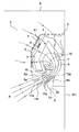
以下に本発明の実施形態を図面を参照して説明する。説明の便宜上、従来例の図15〜図17と同一の部分については同一の符号を付している。図1は第1実施形態の空気調和機を示す概略側面断面図である(後述する図3のD断面を示している)。空気調和機の室内機1は、キャビネット2により本体部が保持されており、キャビネット2には上面側と前面側に吸込口4が設けられたフロントパネル3が着脱自在に取り付けられている。
【0023】
キャビネット2は後方側面に爪部(不図示)が設けられ、居室の側壁W1に取り付けられた取付板(不図示)に該爪部を係合することにより支持される。フロントパネル3の下端部とキャビネット2の下端部との間隙には、第1、第2開口部5a、5bから成る吹出口5が設けられている。第1、第2開口部5a、5bは室内機1の幅方向に延びる略矩形に形成されている。第1開口部5aは、前方下方に臨んで設けられている。第2開口部5bは第1開口部5aよりも後方のキャビネット2の下面に下方に臨んで配されている。
【0024】
室内機1の内部には、吸込口4から吹出口5に連通する送風経路6が形成されている。送風経路6内には空気を送出する送風ファン7が配されている。送風ファン7として、例えば、クロスフローファン等を用いることができる。送風経路6は第1開口部5aに向かって前方に空気を導く主経路6aと第2開口部5bに向かって略鉛直下方に空気を導く分岐経路6bとを有している。
【0025】
送風経路6内の第1開口部5aの近傍には、外部に臨んで上下方向の吹出角度を略水平乃至下方向に変更可能な横ルーバ(前方風向板)11a、11bが設けられている。分岐経路6bの内側端部には、回動軸15aでキャビネット2に枢支される切替板15が設けられている。
【0026】
切替板15により分岐経路6bを遮蔽すると、切替板15が送風経路6の内壁面を形成して第1開口部5aに気流を案内する。これにより、送風経路6を流通する空気の通風抵抗の増加を防止するようになっている。また、切替板15により分岐経路6bを開放すると、送風経路6を流通する気流は分岐経路6bに滑らかに導かれる。尚、切替板15には結露防止のための断熱処理が施されている。
【0027】
また、切替板15の片面には左右方向の吹出角度を変更可能な縦ルーバ12aが設けられている。縦ルーバ12aは、切替板15の開閉に伴い送風経路6内を回動軸15aを中心に回動するため、回動の際に送風経路6の壁面と干渉しない構成になっている。
【0028】
フロントパネル3に対向する位置には、吸込口4から吸い込まれた空気に含まれる塵埃を捕集・除去するエアフィルタ8が設けられている。送風経路6中の送風ファン7とエアフィルタ8との間には、室内熱交換器9が配置されている。室内熱交換器9は屋外に配される圧縮機(不図示)に接続されており、圧縮機の駆動により冷凍サイクルが運転される。
【0029】
冷凍サイクルの運転によって冷房時には室内熱交換器9が周囲温度よりも低温に冷却される。また、暖房時には、室内熱交換器9が周囲温度よりも高温に加熱される。尚、室内熱交換器9とエアフィルタ8との間には吸い込まれた空気の温度を検知する温度センサ61が設けられ、室内機1の側部には空気調和機の駆動を制御する制御部(不図示)が設けられている。室内熱交換機9の前後の下部には冷房または除湿時に室内熱交換器9から落下した結露を補集するドレンパン10が設けられている。
【0030】
上記構成の空気調和機において、空気調和機の運転を開始すると、送風ファン7が回転駆動され、室外機(不図示)からの冷媒が室内熱交換器9へ流れて冷凍サイクルが運転される。これにより、室内機1内には吸込口4から空気が吸い込まれ、エアフィルタ8によって空気中に含まれる塵埃が除去される。
【0031】
室内機1内に取り込まれた空気は室内熱交換器9と熱交換し、冷却または加熱される。送風経路6は切替板15によって分岐経路6bが閉じられ、調和空気が主経路6bを通って第1開口部5aに導かれる。調和空気は縦ルーバ12a及び横ルーバ11a、11bによって左右方向および上下方向に向きを規制され、矢印Aに示すように前方下方に向けて室内に送出される。これにより、室内機1は前方下方に調和空気を送出する前方吹出しの状態になる。
【0032】
また、空気調和機の運転の開始直後は速やかに室内の空気を循環させる必要がある。このため、送風ファン7の回転速度を高くして室内熱交換器9で熱交換された空気は吹出口5から勢いよく送出される。これにより、調和空気は第1開口部5a(図1参照)から前方下方に例えば風速約6〜7m/秒で矢印Aに示すように送出され、居室内を循環する。
【0033】
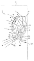
暖房運転を開始して一定の時間が経過した場合や、吸込口4より取込んだ空気の温度と設定温度との差が所定温度よりも大きい場合には、図2に示すように下方吹出しに切り替えられる。下方吹出しでは、切替板15が矢印J方向に回動して主経路6aが閉じられるとともに分岐経路6bが開放される。
【0034】
これにより、吸込口4から取込まれた空気は分岐経路6bを流通して第2開口部から矢印Cに示すように鉛直下方を含む下方に例えば風速約5〜6m/秒で送出される。第2開口部5bは第1開口部5aよりも後方のキャビネット2の下面に設けられているため、送出される調和空気と側壁W1との距離が従来(図16参照)よりも近くなっている。
【0035】
このため、第2開口部5bから送出される調和空気はコアンダ効果によって側壁W1に沿って流通する。また、横ルーバ11a、11bによって第1開口部5aが遮蔽され、第1開口部5aから調和空気が送出されていないことが使用者により視認可能になる。
【0036】
図3はこの時の居室R内の気流の挙動を示している。調和空気は側壁W1に沿って下降して矢印Cに示すように床面F、側壁W1に対向する側壁W2、天井壁Sを順次伝って吸込口4に戻る。これにより、送出された暖気の巻き上がりを防止してショートサーキットによる暖房効率の低下を防止できるとともに、居室Rの下部を充分暖めて快適性を向上させることができる。
【0037】
図4は下方吹出し時の送風ファン7の回転数と風量の関係を示している。縦軸は風量(単位:m3/min)を示し、横軸は送風ファン7の回転数(単位:rpm)を示している。また、図中、K1は本実施形態を表わしており、K2、K3はそれぞれ前述の図16、図17に示す従来の空気調和機の場合を表わしている。
【0038】
同図によると、下方吹出し時に切替板15によって送風経路6を流通する調和空気は略鉛直下方に導かれて第2開口部5bから下方に滑らかに送出されるため、曲がり損失が小さく圧力損失が低い。このため、従来例の下方吹出し(図16参照)或いは後方吹出し(図17参照)よりも風量が増加しており、送風効率を向上させることができる。
【0039】
また、図5は下方吹出し時の送風ファン7の風量と騒音との関係を示している。縦軸は騒音(単位:dB)を示し、横軸は風量(単位:m3/min)を示している。また、上記と同様に、図中、K1は本実施形態を表わしており、K2、K3はそれぞれ前述の図16、図17に示す従来の空気調和機の場合を表わしている。
【0040】
同図によると、本実施形態は曲がり損失が小さく圧力損失が低いため、従来例の下方吹出し(図16参照)或いは後方吹出し(図17参照)よりも同じ風量の時に騒音が小さくなり、静音性を向上させることができる。
【0041】
吸込口4より取込んだ空気の温度と設定温度との温度差が小さくなったことを温度センサ61により検知すると、送風ファン7の調整により徐々に送風量が低下される。送風量が低下しても、室内機1から下方に送出された調和空気(暖気)はコアンダ効果により巻き上がらずに側壁W1に沿って下降し続け、居住空間に直接降り注がずに床面Fを伝って足元に到達する。従って、使用者に直接風が当たることによる不快感もなく快適性が向上する。
【0042】
更に、使用者に直接風が当たることによる不快感がなく、同時に静音化が確保されているため、吸込口4より取込んだ空気の温度と設定温度との温度差が小さくなっても風量を低下させる必要がない。従って、常に大風量の調和空気を居室R内に供給し続けることができる。
【0043】
尚、切替板15の切り替えを使用者によるリモートコントローラ(不図示)の操作によって行えるようになっている。これにより、第1開口部5aから送風する前方吹出しと第2開口部5bからの送風する下方吹出しとを使用者により任意に選択することができる。
【0044】
次に、図6は第2実施形態の空気調和機の室内機1を示す概略側面断面図である。前述の図1、図2に示す第1実施形態と同様の部分には同一の符号を付している。本実施形態の空気調和機の室内機1は、第1実施形態と以下の点で相違する。
【0045】
第2開口部5bには前後方向の風向を可変する横ルーバ(下方風向板)14が回動軸14aにより枢支されている。切替板15には両面に左右方向の風向を可変する縦ルーバ12a、12bが設けられている。縦ルーバ12a、12bは同軸に結合されており、切替板15の回動の際に送風経路6の壁面と干渉しない構成になっている。その他の部分は第1実施形態と同一である。
【0046】
上記と同様に、空気調和機の運転を開始すると、居室R内の空気が吸込口4から室内機1に吸い込まれる。室内機1内に取り込まれた空気は室内熱交換器9と熱交換し、冷却または加熱される。送風経路6は切替板15によって分岐経路6bが閉じられ、調和空気が主経路6bを通って第1開口部5aに導かれる。
【0047】
調和空気は縦ルーバ12a及び横ルーバ11a、11bによって左右方向および上下方向の向きを規制され、矢印Aに示すように前方下方に向けて室内に送出される。これにより、室内機1は前方に調和空気を送出する前方吹出しの状態になる。また、横ルーバ14によって第2開口部5bが遮蔽され、第2開口部5bから調和空気が送出されていないことが使用者により視認可能になっている。
【0048】
暖房運転を開始して一定の時間が経過した場合や、吸込口4より取込んだ空気の温度と設定温度との差が所定温度よりも大きい場合には、図7に示すように下方吹出しに切り替えられる。下方吹出しでは、切替板15が矢印J方向に回動して主経路6aが閉じられるとともに分岐経路6bが開放される。
【0049】
これにより、吸込口4から取込まれた空気は分岐経路6bを流通して縦ルーバ12b及び横ルーバ14によって左右方向及び前後方向の向きを規制される。そして、第2開口部から矢印Cに示すように後方の側壁W1に向けて例えば風速約5〜6m/秒で送出される。第2開口部5bから送出される調和空気はコアンダ効果によって側壁W1に沿って流通する。
【0050】
また、横ルーバ11a、11bによって第1開口部5aが遮蔽され、第1開口部5aから調和空気が送出されていないことが使用者により視認可能になる。尚、使用者によるリモートコントローラの操作によって、縦ルーバ12bおよび横ルーバ14の向きを可変できるようになっている。
【0051】
本実施形態によると、第1実施形態の空気調和機と同様に、下方吹出し時に切替板15によって第2開口部5bに向かって略鉛直下方に調和空気が導かれるので圧力損失を低減することができる。従って、前述の図4、図5に示す第1実施形態(K1)と同様の風量及び騒音レベルを得ることができ、送風効率の低下防止及び静音化を図ることができる。
【0052】
尚、前方下方へ調和空気を送出する第1開口部5aよりも第2開口部5bが後方に配置されているため、横ルーバ14の向きを後方に大きく向けなくても下方に送出された調和空気を壁面W1に沿って流通させることができる。これにより、風量及び騒音レベルの増加が抑制されている。
【0053】
また、縦ルーバ12bおよび横ルーバ14の向きを可変することにより第2開口部から送出する調和空気の風向を可変することができる。このため、使用者の様々な要望に対応可能となる。加えて、横ルーバ14によって第2開口部5bから後方下方へ調和空気を送出できるため、側壁W1を伝う調和空気の到達距離を増加させることができる。従って、より大風量の暖気を床面Fに導くことができる。
【0054】
次に、図8は第3実施形態の空気調和機の室内機を示す断面図である。説明の便宜上、前述の図6、図7に示す第2実施形態と同様の部分には同一の符号を付している。本実施形態は、第2実施形態の切替板15(図6参照)が省かれている。縦ルーバ12a、12b(図6参照)はキャビネット2及びフロントパネル3に取付けられており図中の記載を省略している。
【0055】
前方吹出し時には横ルーバ14により第2開口部5bが閉じられ、主経路6aを通る調和空気は第1開口部5aから送出される。この時、分岐経路6bに進入した空気により渦25が発生し、渦25が空気の流通経路の壁面となる。これにより、調和空気がスムーズに前方の第1開口部5aへ導かれ、圧力損失を増加させることなく前方下方に調和空気を送出することができる。
【0056】
下方吹出し時には図9に示すように、横ルーバ11a、11bにより第1開口部5aが閉じられ、分岐経路6bを通る調和空気は第2開口部5bから送出される。この時、主経路6aに進入した空気により渦26が発生し、渦26が空気の流通経路の壁面となる。これにより、調和空気がスムーズに下方の第2開口部5bへ導かれ、圧力損失を増加させることなく下方に調和空気を送出することができる。
【0057】
次に、図10は第4実施形態の空気調和機の室内機を示す断面図である。説明の便宜上、前述の図1、図2に示す第1実施形態と同様の部分には同一の符号を付している。本実施形態の室内機21は、図14に示すように居室Rの隣接する2側壁W3、W4が交差したコーナーLの天井壁Sに接する位置に取り付けられた、所謂コーナーエアコンになっている。図10は図14における一点鎖線Eで切断した断面を示している。
【0058】
図10において、室内機21のキャビネット2の側壁W3、W4(図14参照)に接する面には爪部(不図示)が設けられており、側壁W3、W4に取り付けられた取付板(不図示)に該爪部を嵌合することにより支持される。キャビネット2の前面側には断面円弧状のフロントパネル3が設けられ、フロントパネル3には吸込口4が設けられている。フロントパネル3の下端とキャビネット2の下端との間には第1、第2開口部5a、5bから成る吹出口5が形成されている。
【0059】
室内機21の内部には、吸込口4から吹出口5に連通する送風経路6が形成されている。送風経路6内のキャビネット2の前方には空気を送出する送風ファン7が配されている。送風ファン7として、例えばクロスフローファン、シロッコファン、ターボファン等を用いることができる。
【0060】
送風経路6は第1開口部5aに向かって前方に空気を導く主経路6aと第2開口部5bに向かって下方に空気を導く分岐経路6bとを有している。送風経路6内の第1開口部5aの近傍には、外部に臨んで上下方向の吹出角度を略水平乃至下方向に変更可能な横ルーバ(前方風向板)11が設けられている。第2開口部5aの近傍には、回動可能な切替板15が設けられている。尚、左右方向の風向を可変する縦ルーバ12a(図1参照)の記載を省略している。
【0061】
上記構成の室内機21において、前方吹出し時には図11に示すように、切替板15が分岐経路6bを遮蔽するように配置され、送風経路6を流通する調和空気は切替板15に沿って主経路6aを通って前方に導かれ、横ルーバ11で風向を可変して第1開口部5aから矢印Aに示すように前方に送出される。
【0062】
下方吹出し時には、図12に示すように切替板15によって主経路6aが遮蔽されるとともに横ルーバ11によって第1開口部5aが遮蔽される。送風経路6を流通する調和空気は切替板15に沿って分岐経路6bを通って略鉛直下方に導かれ、第2開口部5bから矢印Cに示すように下方に送出される。
【0063】
これにより、図14に示すように、調和空気はコーナーL及び側壁W3、W4に沿って下降し、矢印Cに示すように床面F、側壁W3、W4に対向する側壁W5、W6、天井壁Sを順次伝って吸込口4に戻る。これにより暖気が居室R内を循環して暖房運転が行われる。
【0064】
また、下方吹出し時に図13に示すように、横ルーバ11によって第1開口部5aを遮蔽し、切替板15によって第2開口部5bから送出される調和空気の向きを可変してもよい。この時、送風経路6を流通して主経路6aに侵入した空気により発生する渦27によって調和空気が分岐経路6bを通って略鉛直下方に導かれる。
【0065】
そして、切替板15で風向を可変して第2開口部5bから矢印Cに示すように後方下方に送出される。これにより、渦27の発生によって図12の場合に比して送風効率が若干低下するが、風向を自在に調節して調和空気を壁面W1に確実に沿わせることができる。
【0066】
本実施形態によると、第1、第2実施形態と同様に、切替板15によって第2開口部5bに向かって略鉛直下方に調和空気が導かれるので圧力損失を低減することができる。従って、前述の図4、図5に示す第1実施形態(K1)と同様の風量及び騒音レベルを得ることができ、送風効率の低下防止及び静音化を図ることができる。
【0067】
尚、第2実施形態と同様に、切替板15に加えて第2開口部5bに風向を可変する横ルーバを設けると、渦27を発生させることなくコーナーLに向けて後方へ送出された調和空気をより遠くまでコーナーLに沿って流通させることができる。
【0068】
以上により、本発明に係る空気調和機を第1〜第4実施形態により説明したが、本発明は上記実施形態に限定される訳ではなく、本発明の趣旨を逸脱しない範囲で適宜の変更を加えて実施することができる。
【0069】
【発明の効果】
本発明によると、前方下方に調和空気を送出する第1開口部よりも後方に設けた第2開口部により下方に調和空気を送出するので、空気調和機を取り付ける壁面と第2開口部との距離を接近させることができる。これにより、第2開口部から調和空気を下方に送出して圧力損失や騒音の増加を抑制して容易に壁面に沿って流通させることができる。従って、送出された暖気の巻き上がりを防止してショートサーキットによる暖房効率の低下を防止できるとともに、居室Rの下部を充分暖めて快適性を向上させることができる。
【0070】
また本発明によると、送風経路を流通する調和空気を第1開口部に向かう前方に導く主経路と第2開口部に向かう略鉛直下方に導く分岐経路とを設けたので、前方吹出し及び下方吹出し時の圧力損失及び騒音の増加を更に低減することができる。
【0071】
また本発明によると、調和空気の流通経路を主経路と分岐経路とに切り替える切替板を設けたので、切替板により流通経路の壁面を構成してスムーズに第1、第2開口部に調和空気を導くことができる。
【0072】
また本発明によると、下吹出し時に第2開口部から調和空気を鉛直下方よりも後方へ吹き出すことができるので、壁面やコーナーを伝う調和空気の到達距離を増加させることができる。従って、より大風量の暖気を床面に導くことができる。
【0073】
また本発明によると、風向を可変する下方風向板によって前方吹出し時に第2開口部を遮蔽できるので、前方吹出し状態を容易に視認できるとともに第2開口部を遮蔽する部材を設ける必要がなく部品点数を削減することができる。
【0074】
また本発明によると、風向を可変する前方風向板によって下方吹出し時に第1開口部を遮蔽できるので、下方吹出し状態を容易に視認できるとともに第1開口部を遮蔽する部材を設ける必要がなく部品点数を削減することができる。
【0075】
また本発明によると、筐体内に取り入れた空気の温度を検知する温度検知手段を設けたので、温度検知手段の検知結果に基づいて前方吹出しと下方吹出しとを容易に切り替えることができる。
【図面の簡単な説明】
【図1】は、本発明の第1実施形態の空気調和機の室内機の前方吹出しの状態を示す側面断面図である。
【図2】は、本発明の第1実施形態の空気調和機の室内機の下方吹出しの状態を示す側面断面図である。
【図3】は、本発明の第1実施形態の空気調和機による居室内の気流の挙動を示す透視斜視図である。
【図4】は、本発明の第1実施形態の空気調和機の室内機の送風ファンの回転数と風量の関係を示す図である。
【図5】は、本発明の第1実施形態の空気調和機の室内機の送風ファンの風量と騒音の関係を示す図である。
【図6】は、本発明の第2実施形態の空気調和機の室内機の前方吹出しの状態を示す側面断面図である。
【図7】は、本発明の第2実施形態の空気調和機の室内機の下方吹出しの状態を示す側面断面図である。
【図8】は、本発明の第3実施形態の空気調和機の室内機の前方吹出しの状態を示す側面断面図である。
【図9】は、本発明の第3実施形態の空気調和機の室内機の下方吹出しの状態を示す側面断面図である。
【図10】は、本発明の第4実施形態の空気調和機の室内機を示す側面断面図である。
【図11】は、本発明の第4実施形態の空気調和機の室内機の前方吹出しの状態を示す側面断面図である。
【図12】は、本発明の第4実施形態の空気調和機の室内機の下方吹出しの状態を示す側面断面図である。
【図13】は、本発明の第4実施形態の空気調和機の室内機の下方吹出しの他の態様を示す側面断面図である。
【図14】は、本発明の第4実施形態の空気調和機による居室内の気流の挙動を示す透視斜視図である。
【図15】は、従来の空気調和機の室内機の前方吹出しの状態を示す側面断面図である。
【図16】は、従来の空気調和機の室内機の下方吹出しの状態を示す側面断面図である。
【図17】は、他の従来の空気調和機の室内機の後方吹出しの状態を示す側面断面図である。
【符号の説明】
1、21 室内機
2 キャビネット
3 フロントパネル
4 吸込口
5 吹出口
5a 第1開口部
5b 第2開口部
6 送風経路
6a 主経路
6b 分岐経路
7 送風ファン
8 エアフィルタ
9 室内熱交換器
10 ドレンパン
11、11a、11b、14 横ルーバ
12、12a、12b 縦ルーバ
15 切替板
25、26、27 渦
61 温度センサ[0001]
TECHNICAL FIELD OF THE INVENTION
The present invention relates to an air conditioner that conditioned intake air and sends the conditioned air indoors.
[0002]
[Prior art]
FIG. 15 is a schematic side sectional view showing an indoor unit of a conventional air conditioner disclosed in Japanese Patent Application No. 2002-266437. The
[0003]
A
[0004]
Inside the
[0005]
The
[0006]
Between the
[0007]
Drain
[0008]
In the vicinity of the
[0009]
In the air conditioner having the above configuration, when heating of the air conditioner is started, the
[0010]
The air taken in the
[0011]
When the difference between the room temperature and the set temperature is larger than a predetermined temperature, the
[0012]
Further, since the specific gravity of the warm air is small, a part of the air flow sent out from the
[0013]
As a result, the air sent downward and rearward from the
[0014]
[Problems to be solved by the invention]
However, according to the above-described conventional air conditioner, the air flowing through the air blowing
[0015]
The present invention has been made in view of the above problems, and an object of the present invention is to provide an air conditioner that can ensure the comfort during heating and improve the blowing efficiency and the quietness.
[0016]
[Means for Solving the Problems]
In order to achieve the above object, the present invention provides an air conditioner that sends out conditioned air passing through a ventilation path provided in a housing from an outlet, a first opening capable of sending conditioned air downward and forward, and a first opening. A second opening that is disposed rearward of the portion and that sends out conditioned air downward, is provided in the outlet, and the conditioned air is sent out alternatively from the first and second openings.
[0017]
According to this configuration, the conditioned air is sent from the first opening toward the lower front side between the horizontal direction and the vertically lower side. When the delivery direction is switched, the conditioned air is delivered downward from the second opening. At this time, since the second opening disposed behind the first opening is opened at a position close to the wall surface, the conditioned air sent out from the second opening flows along the wall surface by the Coanda effect.
[0018]
Further, the present invention is characterized in that, in the air conditioner having the above configuration, the blowing path has a main path for guiding conditioned air to the first opening and a branch path for guiding conditioned air to the second opening. . According to this configuration, the conditioned air flowing through the main path is sent downward from the first opening toward the front, and the conditioned air flowing through the branch path is sent downward from the second opening. The main path guides the conditioned air forward, and the branch path guides the conditioned air substantially vertically downward, thereby reducing the pressure loss of the conditioned air delivered.
[0019]
Further, the present invention is characterized in that, in the air conditioner having the above configuration, a switching plate for selectively switching a flow path of the conditioned air between the main path and the branch path is provided. According to this configuration, at the time of forward blowing, the air flow path is switched by the switching plate so that air flows forward toward the first opening, and the conditioned air is sent forward from the first opening through the air blowing path. Is done. At the time of downward blowing, the air flow path is switched by the switching plate so that air flows toward the second opening, and the conditioned air can be sent downward from the second opening through the air blowing path.
[0020]
In addition, the back from the indoor unit indicates a direction toward a wall surface or a corner where the indoor unit is installed, and the front indicates a direction opposite to the wall surface or the corner where the indoor unit is installed. In addition, the upper surface of the indoor unit refers to the ceiling-side surface of the room where the
[0021]
When the conditioned air can be blown backward from the second opening vertically downward from the second opening by the lower wind direction plate or the like provided in the second opening, the conditioned air can flow far along the wall surface. Can be. If the first and second openings can be shielded by the front wind direction plate arranged in the first opening and the lower wind direction plate arranged in the second opening, the number of components can be reduced. Further, if a temperature detecting means for detecting the intake air temperature is provided, it is possible to switch between forward blowing and downward blowing based on the detection result of the temperature detecting means.
[0022]
BEST MODE FOR CARRYING OUT THE INVENTION
Hereinafter, embodiments of the present invention will be described with reference to the drawings. For convenience of description, the same parts as those in FIGS. 15 to 17 of the conventional example are denoted by the same reference numerals. FIG. 1 is a schematic side sectional view showing the air conditioner of the first embodiment (showing a D section in FIG. 3 described later). The main unit of the
[0023]
The
[0024]
Inside the
[0025]
In the vicinity of the
[0026]
When the
[0027]
On one surface of the switching
[0028]
At a position facing the
[0029]
During the cooling operation, the
[0030]
In the air conditioner having the above configuration, when the operation of the air conditioner is started, the
[0031]
The air taken into the
[0032]
Immediately after the start of the operation of the air conditioner, it is necessary to circulate the indoor air promptly. Therefore, the air that has been heat-exchanged in the
[0033]
When a certain period of time has elapsed since the start of the heating operation, or when the difference between the temperature of the air taken in from the
[0034]
Thereby, the air taken in from the
[0035]
For this reason, the conditioned air sent from the
[0036]
FIG. 3 shows the behavior of the air flow in the living room R at this time. The conditioned air descends along the side wall W1 and returns along the floor surface F, the side wall W2 facing the side wall W1, and the ceiling wall S as shown by the arrow C, and returns to the
[0037]
FIG. 4 shows the relationship between the number of rotations of the
[0038]
According to the figure, the conditioned air flowing through the
[0039]
FIG. 5 shows the relationship between the air volume of the
[0040]
According to this figure, since the bending loss is small and the pressure loss is low in this embodiment, the noise is smaller when the air volume is the same as that of the conventional downward blow (see FIG. 16) or the rear blow (see FIG. 17), and the noise is reduced. Can be improved.
[0041]
When the
[0042]
Furthermore, since there is no discomfort caused by direct wind blow to the user, and at the same time silence is ensured, even if the temperature difference between the temperature of the air taken in from the
[0043]
The switching of the switching
[0044]
Next, FIG. 6 is a schematic side sectional view showing the
[0045]
A horizontal louver (lower wind direction plate) 14 that changes the wind direction in the front-rear direction is pivotally supported by the
[0046]
Similarly to the above, when the operation of the air conditioner is started, the air in the living room R is sucked into the
[0047]
The conditioned air is regulated in the left-right direction and the up-down direction by the
[0048]
When a certain period of time has elapsed since the start of the heating operation, or when the difference between the temperature of the air taken in from the
[0049]
Thereby, the air taken in from the
[0050]
Further, the
[0051]
According to the present embodiment, similarly to the air conditioner of the first embodiment, the conditioned air is guided substantially vertically downward toward the
[0052]
In addition, since the
[0053]
Further, by changing the directions of the
[0054]
Next, FIG. 8 is a cross-sectional view illustrating an indoor unit of an air conditioner according to a third embodiment. For convenience of explanation, the same parts as those in the second embodiment shown in FIGS. 6 and 7 are denoted by the same reference numerals. In the present embodiment, the switching plate 15 (see FIG. 6) of the second embodiment is omitted. The
[0055]
At the time of forward blowing, the
[0056]
At the time of downward blowing, as shown in FIG. 9, the
[0057]
Next, FIG. 10 is a cross-sectional view illustrating an indoor unit of an air conditioner according to a fourth embodiment. For the sake of convenience of explanation, the same parts as those in the first embodiment shown in FIGS. 1 and 2 are denoted by the same reference numerals. As shown in FIG. 14, the
[0058]
10, a claw portion (not shown) is provided on a surface of the
[0059]
Inside the
[0060]
The blowing
[0061]
In the
[0062]
At the time of downward blowing, as shown in FIG. 12, the
[0063]
Thereby, as shown in FIG. 14, the conditioned air descends along the corner L and the side walls W3, W4, and as shown by the arrow C, the side walls W5, W6 facing the floor surface F, the side walls W3, W4, and the ceiling wall. S is sequentially transmitted to return to the
[0064]
Further, as shown in FIG. 13, the
[0065]
Then, the wind direction is changed by the switching
[0066]
According to the present embodiment, as in the first and second embodiments, the conditioned air is guided substantially vertically downward by the switching
[0067]
As in the second embodiment, when a horizontal louver for changing the wind direction is provided in the
[0068]
As described above, the air conditioner according to the present invention has been described with reference to the first to fourth embodiments. However, the present invention is not limited to the above-described embodiments, and appropriate modifications may be made without departing from the spirit of the present invention. In addition, it can be implemented.
[0069]
【The invention's effect】
According to the present invention, the conditioned air is sent downward by the second opening provided rearward of the first opening for sending the conditioned air forward and downward. The distance can be reduced. Thereby, the conditioned air can be sent downward from the second opening to suppress pressure loss and increase in noise, and can easily flow along the wall surface. Therefore, it is possible to prevent the sent out warm air from rising and prevent a decrease in the heating efficiency due to the short circuit, and to sufficiently warm the lower part of the living room R to improve the comfort.
[0070]
Further, according to the present invention, the main path for guiding the conditioned air flowing through the air supply path to the front toward the first opening and the branch path for guiding the conditioned air substantially vertically downward to the second opening are provided, so that the front blowing and the downward blowing are performed. The increase in pressure loss and noise at the time can be further reduced.
[0071]
Further, according to the present invention, since the switching plate for switching the flow path of the conditioned air between the main path and the branch path is provided, the wall of the flow path is constituted by the switching plate, and the conditioned air is smoothly supplied to the first and second openings. Can be led.
[0072]
Further, according to the present invention, since the conditioned air can be blown rearward from the second opening at the time of downward blowing, rather than vertically downward, it is possible to increase the reach of the conditioned air traveling along the wall surface and the corner. Therefore, a larger amount of warm air can be guided to the floor.
[0073]
Further, according to the present invention, since the second opening can be shielded at the time of front blowing by the lower wind direction plate that changes the wind direction, the state of front blowing can be easily visually recognized, and there is no need to provide a member for blocking the second opening, and the number of parts is reduced. Can be reduced.
[0074]
Further, according to the present invention, the first opening can be shielded at the time of downward blowing by the front wind direction plate that changes the wind direction, so that the downward blowing state can be easily visually recognized and there is no need to provide a member for shielding the first opening, and the number of parts is reduced. Can be reduced.
[0075]
Further, according to the present invention, since the temperature detecting means for detecting the temperature of the air taken into the housing is provided, it is possible to easily switch between the front blowing and the downward blowing based on the detection result of the temperature detecting means.
[Brief description of the drawings]
FIG. 1 is a side cross-sectional view showing a state of front blowing of an indoor unit of an air conditioner according to a first embodiment of the present invention.
FIG. 2 is a side sectional view showing a state of downward blowing of the indoor unit of the air conditioner according to the first embodiment of the present invention.
FIG. 3 is a perspective view showing the behavior of airflow in a living room by the air conditioner according to the first embodiment of the present invention.
FIG. 4 is a diagram illustrating a relationship between a rotation speed of a blower fan and an air flow rate of an indoor unit of the air conditioner according to the first embodiment of the present invention.
FIG. 5 is a diagram illustrating a relationship between an air volume of a blower fan and a noise of an indoor unit of the air conditioner according to the first embodiment of the present invention.
FIG. 6 is a side cross-sectional view showing a state of forward blowing of an indoor unit of an air conditioner according to a second embodiment of the present invention.
FIG. 7 is a side sectional view showing a state of downward blowing of an indoor unit of an air conditioner according to a second embodiment of the present invention.
FIG. 8 is a side cross-sectional view showing a state of front blowing of an indoor unit of an air conditioner according to a third embodiment of the present invention.
FIG. 9 is a side sectional view showing a state of downward blowing of an indoor unit of an air conditioner according to a third embodiment of the present invention.
FIG. 10 is a side sectional view showing an indoor unit of an air conditioner according to a fourth embodiment of the present invention.
FIG. 11 is a side cross-sectional view showing a state of forward blowing of an indoor unit of an air conditioner according to a fourth embodiment of the present invention.
FIG. 12 is a side sectional view showing a state of downward blowing of an indoor unit of an air conditioner according to a fourth embodiment of the present invention.
FIG. 13 is a side sectional view showing another mode of downward blowing of the indoor unit of the air conditioner according to the fourth embodiment of the present invention.
FIG. 14 is a perspective view showing a behavior of an airflow in a living room by an air conditioner according to a fourth embodiment of the present invention.
FIG. 15 is a side cross-sectional view showing a state in which a conventional air conditioner indoor unit blows forward.
FIG. 16 is a side sectional view showing a state of downward blowing of an indoor unit of a conventional air conditioner.
FIG. 17 is a side cross-sectional view showing a state of rear blowing of an indoor unit of another conventional air conditioner.
[Explanation of symbols]
1,21 indoor unit
2 cabinets
3 Front panel
4 Suction port
5 outlet
5a First opening
5b 2nd opening
6 Ventilation path
6a Main route
6b Branch route
7 blower fan
8 Air filter
9 indoor heat exchanger
10 drain pan
11, 11a, 11b, 14 Horizontal louver
12, 12a, 12b Vertical louver
15 Switching board
25, 26, 27 vortex
61 Temperature sensor
Claims (8)
Priority Applications (1)
| Application Number | Priority Date | Filing Date | Title |
|---|---|---|---|
| JP2003098735A JP2004308930A (en) | 2003-04-02 | 2003-04-02 | Air conditioner |
Applications Claiming Priority (1)
| Application Number | Priority Date | Filing Date | Title |
|---|---|---|---|
| JP2003098735A JP2004308930A (en) | 2003-04-02 | 2003-04-02 | Air conditioner |
Publications (1)
| Publication Number | Publication Date |
|---|---|
| JP2004308930A true JP2004308930A (en) | 2004-11-04 |
Family
ID=33463387
Family Applications (1)
| Application Number | Title | Priority Date | Filing Date |
|---|---|---|---|
| JP2003098735A Pending JP2004308930A (en) | 2003-04-02 | 2003-04-02 | Air conditioner |
Country Status (1)
| Country | Link |
|---|---|
| JP (1) | JP2004308930A (en) |
Cited By (12)
| Publication number | Priority date | Publication date | Assignee | Title |
|---|---|---|---|---|
| JP2008111577A (en) * | 2006-10-30 | 2008-05-15 | Sharp Corp | Air conditioner |
| JP2011047624A (en) * | 2009-08-28 | 2011-03-10 | Toshiba Carrier Corp | Indoor unit of air conditioner |
| WO2014097686A1 (en) * | 2012-12-19 | 2014-06-26 | 三菱電機株式会社 | Air conditioner |
| WO2014097685A1 (en) * | 2012-12-19 | 2014-06-26 | 三菱電機株式会社 | Air conditioner |
| CN103982996A (en) * | 2013-02-08 | 2014-08-13 | 珠海格力电器股份有限公司 | Air conditioner |
| JP2016080219A (en) * | 2014-10-14 | 2016-05-16 | 三菱電機株式会社 | Air blower and air conditioner with the same |
| JP6065959B1 (en) * | 2015-09-30 | 2017-01-25 | ダイキン工業株式会社 | air conditioner |
| CN107726449A (en) * | 2017-09-12 | 2018-02-23 | 广东美的制冷设备有限公司 | Air conditioner |
| CN107726585A (en) * | 2017-09-12 | 2018-02-23 | 广东美的制冷设备有限公司 | Air conditioner |
| CN110779152A (en) * | 2019-11-15 | 2020-02-11 | 宁波奥克斯电气股份有限公司 | Air conditioner return air control method and device, air conditioner and storage medium |
| CN114076392A (en) * | 2020-08-17 | 2022-02-22 | 广东美的制冷设备有限公司 | Control method of air conditioner, air conditioner and computer storage medium |
| CN114076383A (en) * | 2020-08-17 | 2022-02-22 | 广东美的制冷设备有限公司 | Control method of air conditioner, air conditioner and computer storage medium |
-
2003
- 2003-04-02 JP JP2003098735A patent/JP2004308930A/en active Pending
Cited By (24)
| Publication number | Priority date | Publication date | Assignee | Title |
|---|---|---|---|---|
| JP2008111577A (en) * | 2006-10-30 | 2008-05-15 | Sharp Corp | Air conditioner |
| JP2011047624A (en) * | 2009-08-28 | 2011-03-10 | Toshiba Carrier Corp | Indoor unit of air conditioner |
| CN102003779A (en) * | 2009-08-28 | 2011-04-06 | 东芝开利株式会社 | Indoor machine of an air conditioner |
| WO2014097686A1 (en) * | 2012-12-19 | 2014-06-26 | 三菱電機株式会社 | Air conditioner |
| WO2014097685A1 (en) * | 2012-12-19 | 2014-06-26 | 三菱電機株式会社 | Air conditioner |
| US9696051B2 (en) | 2012-12-19 | 2017-07-04 | Mitsubishi Electric Corporation | Air conditioner |
| CN104854411A (en) * | 2012-12-19 | 2015-08-19 | 三菱电机株式会社 | Air conditioner |
| CN104870909A (en) * | 2012-12-19 | 2015-08-26 | 三菱电机株式会社 | Air conditioner |
| JP5908119B2 (en) * | 2012-12-19 | 2016-04-26 | 三菱電機株式会社 | Air conditioner |
| CN103982996B (en) * | 2013-02-08 | 2017-05-10 | 珠海格力电器股份有限公司 | Air conditioner |
| CN103982996A (en) * | 2013-02-08 | 2014-08-13 | 珠海格力电器股份有限公司 | Air conditioner |
| JP2016080219A (en) * | 2014-10-14 | 2016-05-16 | 三菱電機株式会社 | Air blower and air conditioner with the same |
| AU2016331555B2 (en) * | 2015-09-30 | 2018-05-31 | Daikin Industries, Ltd. | Air conditioning indoor unit |
| WO2017057298A1 (en) * | 2015-09-30 | 2017-04-06 | ダイキン工業株式会社 | Air conditioner |
| JP6065959B1 (en) * | 2015-09-30 | 2017-01-25 | ダイキン工業株式会社 | air conditioner |
| CN108139103A (en) * | 2015-09-30 | 2018-06-08 | 大金工业株式会社 | Air conditioner |
| CN108139103B (en) * | 2015-09-30 | 2019-05-03 | 大金工业株式会社 | Air conditioner |
| CN107726449A (en) * | 2017-09-12 | 2018-02-23 | 广东美的制冷设备有限公司 | Air conditioner |
| CN107726585A (en) * | 2017-09-12 | 2018-02-23 | 广东美的制冷设备有限公司 | Air conditioner |
| CN110779152A (en) * | 2019-11-15 | 2020-02-11 | 宁波奥克斯电气股份有限公司 | Air conditioner return air control method and device, air conditioner and storage medium |
| CN110779152B (en) * | 2019-11-15 | 2021-12-21 | 宁波奥克斯电气股份有限公司 | Air conditioner return air control method and device, air conditioner and storage medium |
| CN114076392A (en) * | 2020-08-17 | 2022-02-22 | 广东美的制冷设备有限公司 | Control method of air conditioner, air conditioner and computer storage medium |
| CN114076383A (en) * | 2020-08-17 | 2022-02-22 | 广东美的制冷设备有限公司 | Control method of air conditioner, air conditioner and computer storage medium |
| CN114076383B (en) * | 2020-08-17 | 2023-05-30 | 广东美的制冷设备有限公司 | Air conditioner control method, air conditioner and computer storage medium |
Similar Documents
| Publication | Publication Date | Title |
|---|---|---|
| JP4907176B2 (en) | Air conditioner | |
| WO2004013542A1 (en) | Air conditioner | |
| WO2005052462A1 (en) | Air conditioner | |
| JP5268668B2 (en) | Air conditioner | |
| JP6357258B2 (en) | Air conditioning method and air conditioner | |
| JP4017483B2 (en) | Air conditioner | |
| JP4285959B2 (en) | Air conditioner | |
| JP4708199B2 (en) | Air conditioner | |
| JP2004308930A (en) | Air conditioner | |
| KR20200119576A (en) | Air conditioner | |
| JP2005164067A (en) | Air conditioner | |
| JP4458826B2 (en) | Air conditioner | |
| JP2004361011A (en) | Air conditioner | |
| WO2005052463A1 (en) | Air conditioner | |
| JP6075088B2 (en) | Air conditioner | |
| JP4619983B2 (en) | Air conditioner | |
| JP2003106555A (en) | Air conditioner | |
| JP2012042182A (en) | Indoor unit of air conditioner | |
| JP5486576B2 (en) | Air conditioner | |
| JP5567542B2 (en) | Air conditioning method and air conditioner | |
| JP2009058220A (en) | Air conditioning method and air-conditioner | |
| JP6081955B2 (en) | Air conditioner | |
| JP4851629B2 (en) | Air conditioning method and air conditioner | |
| JP2004218894A (en) | Air conditioner and air conditioning method | |
| JP2015099009A (en) | Air conditioning method and air conditioner |
Legal Events
| Date | Code | Title | Description |
|---|---|---|---|
| A621 | Written request for application examination |
Free format text: JAPANESE INTERMEDIATE CODE: A621 Effective date: 20050810 |
|
| RD01 | Notification of change of attorney |
Free format text: JAPANESE INTERMEDIATE CODE: A7421 Effective date: 20070827 |
|
| A977 | Report on retrieval |
Free format text: JAPANESE INTERMEDIATE CODE: A971007 Effective date: 20070907 |
|
| A131 | Notification of reasons for refusal |
Free format text: JAPANESE INTERMEDIATE CODE: A131 Effective date: 20070918 |
|
| A521 | Written amendment |
Free format text: JAPANESE INTERMEDIATE CODE: A523 Effective date: 20071119 |
|
| A02 | Decision of refusal |
Free format text: JAPANESE INTERMEDIATE CODE: A02 Effective date: 20080624 |