JP2004308526A - Exhaust emission cleaning device for internal combustion engine - Google Patents
Exhaust emission cleaning device for internal combustion engine Download PDFInfo
- Publication number
- JP2004308526A JP2004308526A JP2003101925A JP2003101925A JP2004308526A JP 2004308526 A JP2004308526 A JP 2004308526A JP 2003101925 A JP2003101925 A JP 2003101925A JP 2003101925 A JP2003101925 A JP 2003101925A JP 2004308526 A JP2004308526 A JP 2004308526A
- Authority
- JP
- Japan
- Prior art keywords
- fuel
- air
- fuel ratio
- exhaust
- exhaust gas
- Prior art date
- Legal status (The legal status is an assumption and is not a legal conclusion. Google has not performed a legal analysis and makes no representation as to the accuracy of the status listed.)
- Granted
Links
Images


Classifications
-
- Y—GENERAL TAGGING OF NEW TECHNOLOGICAL DEVELOPMENTS; GENERAL TAGGING OF CROSS-SECTIONAL TECHNOLOGIES SPANNING OVER SEVERAL SECTIONS OF THE IPC; TECHNICAL SUBJECTS COVERED BY FORMER USPC CROSS-REFERENCE ART COLLECTIONS [XRACs] AND DIGESTS
- Y02—TECHNOLOGIES OR APPLICATIONS FOR MITIGATION OR ADAPTATION AGAINST CLIMATE CHANGE
- Y02T—CLIMATE CHANGE MITIGATION TECHNOLOGIES RELATED TO TRANSPORTATION
- Y02T10/00—Road transport of goods or passengers
- Y02T10/10—Internal combustion engine [ICE] based vehicles
- Y02T10/40—Engine management systems
Abstract
Description
【0001】
【発明の属する技術分野】
本発明は、内燃機関の排気浄化装置に関する。
【0002】
【従来の技術】
ディーゼル機関や希薄燃焼式ガソリン機関のように酸素過剰状態の混合気を燃焼させて機関運転がなされる内燃機関では、排気中の窒素酸化物(以下、NOxという)を浄化すべく排気浄化装置として、その排気通路にNOx吸収材が設けられる。
【0003】
このようなNOx吸収材は、吸蔵還元型NOx触媒に代表されるように、流入排気の空燃比が高いときその排気中のNOxを吸収し、流入排気の空燃比が低いときその吸収していたNOxを放出する性質を備えており、このNOx吸収材を排気通路に配置した場合には、内燃機関より排出されるNOxがこのNOx吸収材に吸収され、適宜、排気中への燃料添加による還元雰囲気で放出される。
【0004】
また、内燃機関の燃料中には、通常、硫黄分なども含まれており、機関燃焼時には、NOxのみならず、SO2やSO3などの硫黄酸化物(以下、SOxという)も同時に生成され、このSOxもNOxと同様に、NOx吸収材に吸収されるが、時間の経過と共に化学的に安定した硫酸塩(BaSO4)となって、NOx吸収材に蓄積される。
【0005】
このため、NOxを吸収するNOx吸収材本来の機能が阻害されるSOx被毒が生じるので、NOx吸収材に吸収されるSOxは、所定のタイミングにてNOx吸収材より放出させる必要がある。
【0006】
このような目的で排気中に還元剤としての燃料添加する装置が知られているが、例えば、内燃機関の排気通路にNOx吸収材を設け、このNOx吸収材より上流に還元剤を供給する還元剤供給手段と、還元剤供給手段によって供給すべき還元剤の量を、NOx吸収材を経て流出した排気の空燃比に基づき補正する還元剤供給量補正手段を備える排気浄化装置がある(例えば、特許文献1参照)。
【0007】
このような排気浄化装置の還元剤供給量補正手段では、NOx吸収材下流の空燃比に基づき、還元剤供給手段にて供給される還元剤の供給量を所定の条件下において必要とされる還元剤の供給量に収束させる、いわゆるフィードバック制御を実施して、燃料添加ノズルから添加される燃料量を決定している。
【0008】
【特許文献1】
特開2002−188430号公報
【0009】
【発明が解決しようとする課題】
しかしながら、上記のようなフィードバック制御を実施しても、なお触媒の温度を正確にコントロールできない場合がある。そこで、内燃機関の筒内の燃焼空燃比の変化に着目したところ、筒内の空燃比の変化を考慮することで、より正確に排気中への必要な燃料添加量を制御できることが見出された。
【0010】
本発明は上記の事情に鑑みてなされたもので、排気系に還元剤として燃料の添加をする場合のフィードバック制御における学習値を、その学習時と同様な筒内の燃焼状態の場合にのみ反映させることで、正確な量の還元剤の添加が行えるようにした内燃機関の排気浄化装置を提供することを技術的課題とする。
【0011】
【課題を解決するための手段】
上記課題を達成するために、本発明は、排気中への燃料の添加を実施するにあたり、ベースとなる筒内の空燃比に対応させて燃料添加による空燃比制御のフィードバック学習値を記憶し、ベースとなる空燃比が同一または近似している場合にその学習値を適用するようにした。
【0012】
すなわち、排気系に設置される排気浄化装置と、
前記排気浄化装置に対して燃料を添加する燃料添加手段と、
前記排気浄化装置下流の空燃比を検出する第1の空燃比検出手段と、を備え、
前記第1の空燃比検出手段により検出された空燃比が目標空燃比になるようにフィードバック値を求め、このフィードバック値を学習値として記憶し、次回以降の燃料添加量に反映させる内燃機関において、
筒内から排出される排気の空燃比を検出する第2の空燃比検出手段をさらに有し、この第2の空燃比検出手段により検出された空燃比に対応させて記憶した学習値を適用して、前記燃料添加手段から添加される燃料量を決定することを特徴とする。
【0013】
このようにすれば、内燃機関の燃焼状態が変化してベースとなる筒内の空燃比が変わっても、排気系への燃料添加のフィードバック制御に際して、常にその燃焼状態に適合した学習値が選択され適用されるので、より正確な燃料の添加が実施できる。
【0014】
この場合、筒内の空燃比を値によって複数の段階に区分し、燃料の添加時の空燃比の値が属する段階に対応する学習値を適用することが好適である。
【0015】
空燃比を値によって区分して定められる段階はいくつであっても良いが、通常は2から4段階程度に分割するのが好適である。
【0016】
前記学習値は、次回の燃料添加時に、筒内の空燃比が所定の対応する段階に属すると判断された場合にのみ反映させることが好ましい。
【0017】
また、本発明は、排気系に設置された触媒のSOx被毒回復制御で前記燃料添加を実施する場合に適用することができる。
【0018】
本発明によれば、排気系への燃料添加のフィードバック制御に際し、内燃機関の燃焼状態に適合した学習値が選択されて適用される。したがって、筒内の燃料がリーンの状態での空燃比学習値と、リッチの状態の空燃比学習値が異なることに起因して、同一の学習値を適用した場合に生じる虞がある触媒の過熱が防止できる。特に、SOx被毒回復制御において、添加される燃料量が必要以上に増大して触媒温度が上昇することが抑制される。
【0019】
【発明の実施の形態】
以下、本発明に係る排気浄化装置の具体的な実施態様を図面に基づいて説明する。図1は、本実施の形態に係る排気浄化装置を適用する内燃機関1とその吸排気系の概略構成を示す図である。
【0020】
図1に示す内燃機関1は、4つの気筒2を有する水冷式の4サイクル・ディーゼル機関である。
【0021】
内燃機関1は、各気筒2の燃焼室に直接燃料を噴射する燃料噴射弁3を備えている。各燃料噴射弁3は、燃料を所定圧まで蓄圧する蓄圧室(コモンレール)4と接続されている。
【0022】
前記コモンレール4は、燃料供給管5を介して燃料ポンプ6と連通し、この燃料ポンプ6から吐出された燃料は、コモンレール4にて所定圧まで蓄圧されて各気筒2の燃料噴射弁3へ分配される。
【0023】
内燃機関1には、吸気枝管8が接続されており、吸気枝管8の各枝管は、各気筒2の燃焼室と吸気ポート(図示省略)を介して連通している。
【0024】
前記吸気枝管8は吸気管9に接続され、吸気枝管8の直上流に位置する部位には、この吸気管9内を流通する吸気の流量を調節する吸気絞り弁13が設けられている。
【0025】
また、吸気管9の上流に設置したエアフローメータ11と前記吸気絞り弁13との間に位置する吸気管9には、排気のエネルギを駆動源として作動する遠心過給機(ターボチャージャ)15のコンプレッサハウジング15aが設けられている。
【0026】
一方、内燃機関1には、排気枝管18が接続され、排気枝管18の各枝管が排気ポート1bを介して各気筒2の燃焼室と連通している。
【0027】
前記排気枝管18は、前記遠心過給機15のタービンハウジング15bと接続されている。前記タービンハウジング15bは、排気管19と接続され、この排気管19は、下流にて大気へと通じている。
【0028】
前記排気管19の途中には、NOx保持材を含む吸蔵還元型NOx触媒20(以下、単にNOx触媒とする。)が設けられている。NOx触媒20は、コージェライトのような多孔質材料から形成され、例えば、アルミナを担体とし、その担体上に、カリウム(K)、ナトリウム(Na)、リチウム(Li)、もしくはセシウム(Cs)等のアルカリ金属と、バリウム(Ba)もしくはカルシウム(Ca)等のアルカリ土類と、ランタン(La)もしくはイットリウム(Y)等の希土類とから選択された少なくとも1つと、白金(Pt)等の貴金属とを担持して構成されている。なお、本実施の形態では、アルミナからなる担体上にバリウム(Ba)と白金(Pt)とを担持し、更に酸素貯蔵(O2ストレージ)能のある例えばセリア(CeO2)等の遷移金属が添加されている。
【0029】
このNOx触媒20は、このNOx触媒20に流入する排気の酸素濃度が高いときは排気中のNOxを保持し、一方、このNOx触媒20に流入する排気の酸素濃度が低下したときは保持していたNOxを離脱させる。その際、排気中に炭化水素(HC)や一酸化炭素(CO)等の還元成分が存在していれば、このNOx触媒20から離脱したNOxが還元される。また、セリア(CeO2)等の遷移金属は、排気の特性に応じて酸素を一時的に保持し、活性化酸素として放出する能力を有する。
【0030】
NOx触媒20より上流の排気管19には、この排気管19内を流通する排気の温度に対応した電気信号を出力する排気温度センサ24が取り付けられている。また、NOx触媒20より下流の排気管19には、該排気管19内を流通する排気中のNOx濃度に対応した電気信号を出力するNOxセンサ23及び排気の空燃比に対応した電気信号を出力する空燃比センサ22が取り付けられている。
【0031】
ところで、内燃機関1が希薄燃焼運転されている場合は、内燃機関1から排出される排気の空燃比がリーン雰囲気となり排気中の酸素濃度が高くなるため、排気中に含まれるNOxがNOx触媒20に保持されることになるが、内燃機関1の希薄燃焼運転が長時間継続されると、NOx触媒20のNOx保持能力が飽和し、排気中のNOxがNOx触媒20にて保持されずに大気中へ放出されてしまう。
【0032】
特に、内燃機関1のようなディーゼル機関では、大部分の運転領域においてリーン空燃比の混合気が燃焼され、それに応じて大部分の運転領域において排気の空燃比がリーン空燃比となるため、NOx触媒20のNOx保持能力が飽和し易い。
【0033】
なお、ここでいうリーン空燃比とは、ディーゼル機関にあっては、例えば20から50の範囲であり、三元触媒ではNOxを浄化できない領域を意味する。したがって、内燃機関1が希薄燃焼運転されている場合は、NOx触媒20のNOx保持能力が飽和する前にNOx触媒20に流入する排気中の酸素濃度を低下させるとともに燃料の濃度を高め、NOx触媒20に保持されたNOxを還元させる必要がある。
【0034】
このように酸素濃度を低下させる方法としては、排気中の燃料添加や、再循環するEGRガス量を増大させて煤の発生量が増加して最大となった後に、更にEGRガス量を増大させる低温燃焼(特許第3116876号参照)、機関出力のための燃料を噴射させる主噴射の後の膨張行程若しくは排気行程中に再度燃料を噴射させる副噴射等の方法が考えられる。排気中の燃料添加では、NOx触媒20より上流の排気管19を流通する排気中に還元剤たる燃料(軽油)を添加する燃料供給機構を備え、この燃料供給機構から排気中へ燃料を添加することにより、NOx触媒20に流入する排気の酸素濃度を低下させるとともに燃料の濃度を高めることができる。
【0035】
燃料供給機構は、図1に示されるように、その噴孔が排気枝管18内に臨むように取り付けられ、後述するECU35からの信号により開弁して燃料を噴射する燃料添加弁28と、前述した燃料ポンプ6から吐出された燃料を前記燃料添加弁28へ導く燃料供給路29と、を備えている。
【0036】
このような燃料供給機構では、燃料ポンプ6から吐出された高圧の燃料が燃料供給路29を介して燃料添加弁28へ印加される。そして、ECU35からの信号により該燃料添加弁28が開弁して排気枝管18内へ還元剤としての燃料が噴射される。
【0037】
燃料添加弁28から排気枝管18内へ噴射された燃料は、排気枝管18の上流から流れてきた排気の酸素濃度を低下させると共に、NOx触媒20に到達し、NOx触媒20に保持されていたNOxを還元することになる。
【0038】
その後、ECU35からの信号により燃料添加弁28が閉弁し、排気枝管18内への燃料の添加が停止される。
【0039】
また、内燃機関1には、クランクシャフトの回転位置に対応した電気信号を出力するクランクポジションセンサ33が設けられている。
【0040】
以上述べたように構成された内燃機関1には、この内燃機関1を制御するための電子制御ユニット(ECU:Electronic Control Unit)35が併設されている。このECU35は、内燃機関1の運転条件や運転者の要求に応じて内燃機関1の運転状態を制御するユニットである。
【0041】
ECU35は、双方向性バス350によって互いに接続されたROM(リードオンリメモリ)352、RAM(ランダムアクセスメモリ)353、CPU(中央制御装置)351、入力ポート356、出力ポート357を備えている。
【0042】
ECU35の入力ポート356には、上記した各種センサの出力信号の他、アクセルペダルの踏込み量を検出するアクセル開度センサ36、クランクシャフトの回転数を検知するクランク角センサ33等が対応したA/D変換器355を介して、又は、直接入力されている。
【0043】
一方、出力ポート357には、燃料噴射弁3、燃料添加弁28などが接続されている。
【0044】
また、ROM(リードオンリメモリ)352上には、各種予備実験に基づき作成された制御マップが各装置に対応して設けられている。CPU351は、入力ポート356に入力された各種センサの出力信号をROM352上に展開された制御マップに照らし合わせ、その制御マップにおいて算出された値に基づく各種制御信号を出力ポート357を介して各種装置に出力する。RAM353は、入力ポート356に入力される各種センサからの出力信号、及び出力ポート367に出力された制御信号などを内燃機関の運転履歴として記録する。そして、CPU351から要求を受けてそのCPU351との間で各種信号の入出力を行う。
【0045】
ECU35では、現在の機関運転に要求される「目標要求トルク」をクランク角センサ33およびアクセル開度センサ36の出力信号等に基づき算出し、この目標要求トルクを得るべく燃料噴射弁3や燃料ポンプ6に出力される制御信号を適時更新して、燃料供給系における燃料供給量の補正を行う。また、各種センサからの出力値に基づき、後述の排気浄化装置における燃料の供給制御などをも同時に実行する。
【0046】
ところで、NOx触媒20に流入する排気の空燃比をスパイク的に目標リッチ空燃比とすることで、このNOx触媒20に保持されたNOxを還元することが可能となる。しかし、NOx触媒20では、NOxを保持する場合と同様のメカニズムでSOxの吸収が生じるが、一旦保持されたSOxはNOxよりも離脱しにくく、酸素濃度が低下した還元雰囲気でNOxの放出が行われてもSOxは離脱せずに、次第にNOx触媒20内に蓄積される。このような硫黄被毒(以下、SOx被毒という)は、NOx触媒20のNOx浄化率を低下させる原因となる。したがって、適宜の時期に、NOx触媒20からSOxを放出させる被毒回復処理を施す必要がある。このようなSOx被毒回復制御は、ECU35によって実行される。
【0047】
上述したSOx被毒のメカニズムはおよそ以下のとおりである。
【0048】
燃料が内燃機関1で燃焼すると、二酸化硫黄(SO2)や三酸化硫黄(SO3)などのSOxが生成される。NOx触媒20に流入する排気の酸素濃度が高いときには、流入排気中の二酸化硫黄(SO2)や三酸化硫黄(SO3)等のSOxが白金(Pt)の表面上で酸化され、硫酸イオン(SO4 2−)の形でNOx触媒20に保持される。
【0049】
さらに、NOx触媒20に吸収された硫酸イオン(SO4 2−)は、酸化バリウム(BaO)と結合して硫酸塩(BaSO4)を形成する。この硫酸塩(BaSO4)は、硝酸バリウム(Ba(NO3)2)に比して安定していて分解し難く、NOx触媒20に流入する排気の酸素濃度が低くなっても分解されずに、NOx触媒20内に残留する。
【0050】
このようにして、NOx触媒20における硫酸塩(BaSO4)の量が増加すると、それに応じてNOxの保持に関与することができる酸化バリウム(BaO)の量が減少するため、NOx触媒20のNOx保持能力が低下してSOx被毒が発生する。
【0051】
NOx触媒20のSOx被毒を解消する方法としては、NOx触媒20の雰囲気温度をおよそ600乃至650℃の高温域まで昇温させるとともに、NOx触媒20に流入する排気の酸素濃度を低くすることにより、NOx触媒20に吸収されている硫酸バリウム(BaSO4)をSO3 −やSO4 −に熱分解し、次いでSO3 −やSO4 −を排気中の炭化水素(HC)や一酸化炭素(CO)と反応させて気体状のSO2 −に還元する方法を例示することができる。
【0052】
本実施の形態では、ECU35は、燃料添加弁28から排気中へ燃料を添加することにより、それらの未燃燃料成分をNOx触媒20において酸化させ、酸化の際に発生する熱によってNOx触媒20の床温を高めるようにする。同時に、各気筒の膨張行程若しくは排気行程時に燃料噴射弁3から副次的に燃料を噴射させても良い。
【0053】
上記したような燃料添加により、NOx触媒20の床温が600℃から650℃程度の高温域まで上昇する。その後も、引き続きNOx触媒20に流入する排気の酸素濃度を低下させるべくECU35は、燃料添加弁28から燃料を噴射する。
【0054】
上述の被毒回復処理が実行されると、NOx触媒20の床温が高い状況下で、NOx触媒20に流入する排気の酸素濃度が低くなるため、NOx触媒20に保持されている硫酸バリウム(BaSO4)がSO3 −やSO4 −に熱分解され、それらSO3 −やSO4 −が排気中の炭化水素(HC)や一酸化炭素(CO)と反応して還元され、以てNOx触媒20のSOx被毒が回復されることになる。
【0055】
なお、このSOx被毒回復制御では、いわゆるリッチスパイクを実行して排気の酸素濃度を低下させる。さらに、1回のリッチスパイクを複数回の燃料噴射により形成し、空燃比が過剰なリッチとならないようにする。
【0056】
ここで、一度に多量の燃料を噴射すると空燃比が過リッチとなる虞があり、NOx触媒20で反応しきれない燃料の一部が下流へ流出することがある。そこで、本実施の形態では、少量の燃料を複数回に分割して、間欠的に噴射することにより、過リッチを抑制しつつリッチ雰囲気を形成するようにしている。
【0057】
前記SOx被毒回復制御では、NOx触媒20から蓄積しているSOxを放出させることが可能な排気の空燃比(目標空燃比)となるように、上記の燃料添加を実施する。このとき、NOx触媒20の下流の空燃比センサ22の値が目標空燃比とすべく、空燃比センサ22の値をフィードバックして燃料添加弁28から排気中に添加される燃料量を制御する。このときの燃料量は、学習値として次回の燃料添加の際の燃料量に反映される。すなわち、燃料添加量は、ベースとなる燃料添加量と学習値から算出される。
【0058】
本実施の形態に示す排気浄化装置では、NOx触媒20の下流に配置される排気管19に空燃比センサ22を取り付け、この空燃比センサ22にて検出される値を燃料の供給量にフィードバックさせて燃料の供給を行っている。
【0059】
ところが、筒内の燃焼空燃比がリーン(例えば、A/F25程度)のときの学習値を、燃焼空燃比がリッチ(例えば、A/F18程度)のときにそのまま適用する場合を想定すると、ベースとなる空燃比がもともとリッチであるために、燃料添加された排気の空燃比は、目標値よりもさらにリッチとなる可能性がある。したがって、このようなフィードバック制御では、過度にNOx触媒20の床温を上昇させてしまう場合があり、このようなときは、NOx触媒20の熱劣化等を引き起こす虞がある。
【0060】
本実施の形態では、全ての場合に同一の学習値を適用するのではなく、筒内の燃焼状態によって保管する学習値を変え、これらの保管した学習値は同一の燃焼状態のときにのみ反映させるようにした。このような制御によれば、燃焼状態に応じた最適な燃料量が添加される。
【0061】
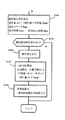
次に、ECU35で処理されるSOx被毒回復制御を、図3に示すフローチャートに基づいて説明する。
【0062】
このフローチャートは、SOx被毒の回復を目的として実施される「SOx被毒回復制御ルーチン」を示すものであるが、NOxの放出作用を促す燃料の供給時などにおいても応用で可能である。
【0063】
まず、ステップS101では、ECU35が機関運転開始からの運転履歴を収集すべく各種センサの出力信号をRAM353上に記憶する。例えば、機関運転開始からの経過時間、目標要求トルクを満たすために各気筒2に供された燃料の供給量、各気筒2に吸入された空気量、前回の燃料供給時からの経過時間、車両走行距離数の積算値、排気温度などである。収集された運転履歴をCPU351に読み出し、SOx被毒回復制御条件、すなわち燃料の供給実行条件が成立しているか否かCPU351内にて判別する。SOx被毒回復制御条件としては、NOx触媒20におけるSOxの吸収量が所定量以上であるか否か、である。この条件が満たされないときは、本処理ルーチンの実行を一旦終了する。
【0064】
前記の条件が満たされたときは、ステップS102に進み、ECU35は筒内燃焼の空燃比がどの範囲にあるかを判断する。ここでは▲1▼18<筒内空燃比<20、▲2▼ 20<筒内空燃比<25、▲3▼ 25<筒内空燃比<30、の範囲にあるかを判断する。この範囲のいずれにも属さないときは、本処理ルーチンの実行を一旦終了する。
【0065】
一方、筒内燃焼の空燃比が、いずれかの範囲に属する場合は、ステップS103に進み、添加燃料の基本供給量の算出を行う。このステップS103では、現在の機関運転に供されている混合気の空燃比と、前記ステップ102にて算出されたSOxの吸収量とをパラメータとしてSOx被毒の回復に供される燃料のベース添加量をROM352上に予め準備されたベース添加量算出マップに基づき算出する。基本供給量算出マップは、各種予備実験に基づき作成されたものである。
【0066】
次に、筒内空燃比が、ステップS102で決定された▲1▼から▲3▼のうちのいずれに属するかによって、以下、適用される学習値がそれぞれ異なるフローにしたがって処理される。
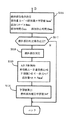
(空燃比が▲1▼の範囲にあるとき)
筒内の空燃比が▲1▼の範囲にあるときは、図4に示すステップS104に進む。ステップS104では、還元剤としての燃料添加の条件を決定する。このときの添加量Aは、前記ベース添加量に、前回の燃料添加の際にフィードバックされた学習値Gmm3を乗じることで求められる。すなわち、基本供給量の増量補正を実施するには、空燃比センサ22にて検出される空燃比と目標空燃比との差に応じて、増量すべき燃料の補正供給量を算出する。
【0067】
一方、基本供給量の減量補正を実施するときも同様に、空燃比センサ22にて検出される空燃比と所定の空燃比との差に応じて、減量すべき燃料の補正供給量を算出する。
【0068】
また、前記添加量Aに基づいて、燃料添加のインターバルBms及び添加時間Csec及び添加休止時間Dsecが決定される。これらは、NOx触媒20の触媒温度がSOxを熱分解し得る高温域に達しているか否か、排気の温度が所定の上限値以下であるか否か、等を考慮して決定されるが、通常は、燃料添加量Aが多ければ、燃料添加のインターバルBmsが短く、添加時間Csecが長く、また添加休止時間Dsecは短く設定される。逆に、添加量が少なければ、燃料添加のインターバルBmsが短く、添加時間Csecが短く、また添加休止時間Dsecは長く設定される。
【0069】
次に、ステップS105に進み、排気中への燃料添加判定条件が成立しているか否かを判定する。条件としては、内燃機関1がSOx被毒回復に適した運転状態であるか、NOx触媒20の温度がSOxを熱分解し得る高温域(例えば、550〜700℃の範囲)であるか否か、また排気の空燃比がストイキより小さいか否か、NOxの吸放出作用を促す燃料の供給が実行状態にあるか否か、などの条件を例示することができる。これらの条件が満たされないときは、本処理ルーチンの実行を一旦終了する。
【0070】
前記ステップS105で肯定判定がなされた場合には、ステップS106へ進み、燃料添加を実行する。
【0071】
次にステップS107では、基本供給量の補正すなわちフィードバック制御を開始すべく、NOx触媒20の下流の実空燃比を空燃比センサ22にて検出すると共に、その実空燃比と目標空燃比との差Eが算出される。
【0072】
この差Eに基づいて、F(係数)との一次元マップからFを求め、添加量を算出する。
【0073】
続いて、ステップS108に進み、前記Fに基づいて学習値Gを算出する。このようにして算出された学習値Gは次回の燃料添加に反映され、このような繰り返しによって目標の空燃比に収束していく。
(空燃比が▲2▼の範囲にあるとき)
筒内の空燃比が▲2▼の範囲にある場合には、図5に示すステップS110に進む。
ステップS110では、燃料添加の条件が決定される。このときの添加量Aは、前記ベース添加量に、前回の燃料添加の際にフィードバックされた学習値Hmm3を乗じることで求められる。
【0074】
ステップS111以下、ステップS115までの行程は、上述した空燃比が▲1▼の場合と同様であるので省略する。
(空燃比が▲3▼の範囲にあるとき)
筒内の空燃比が▲3▼の範囲にある場合には、図6に示すステップS116に進む。
ステップS116では燃料添加の条件を決定する。このときの添加量Aは、前記ベース添加量に、前回の燃料添加の際にフィードバックされた学習値Imm3を乗じることで求められる。
【0075】
ステップS117からステップS121までの行程は、上述した空燃比が▲1▼の場合と同様であるので省略する。
【0076】
本実施の形態では、燃料の供給を行うに際して、排気通路への燃料の供給を実施しているが、機関燃焼に寄与されない燃焼室内への副噴射や、機関燃焼に供される混合気の空燃比を予め低めに設定する空燃比制御などを実施してNOx触媒に燃料を供給してもよい。何れの場合においても、NOx触媒下流の空燃比はフィードバックして燃料の供給量を定めるものとする。
【0077】
また、上記した燃料供給装置の構成は、あくまでも本発明の一実施形態にすぎず、その詳細は所望に応じて変更しても構わない。例えば、機械式の開閉弁である燃料添加弁28を電磁弁とすることができる。また、燃料供給装置を燃料供給系から完全に独立させて構成するなどの変更を行ってもよい。
【0078】
上述の実施の形態では、NOx触媒20下流の空燃比を検出するにあたって、空燃比センサ22を利用しているが、空燃比センサ22に替えて酸素(O2)センサを使用してもよい。
【0079】
また、本実施の形態では、ディーゼル機関に本発明を適用させた例について説明しているが、本発明は、勿論ガソリン機関においても有用である。
【0080】
以上のように、本制御では内燃機関の筒内の空燃比の値に基づいて3つの段階を設定し、それぞれの段階毎に学習値を求めるようにして、次回の燃料添加時における筒内の空燃比がどの段階に属するかを判断して対応する学習値が適用される。したがって、NOx触媒のSOx被毒回復制御の実行時における燃料添加のフィードバック制御に際し、内燃機関の燃焼状態に適合した学習値が選択され、適切な値が燃料添加に反映され、目標値への収束が容易となる。
【0081】
【発明の効果】
以上のように本発明によれば、排気系への燃料添加のフィードバック制御に際し、内燃機関の燃焼状態に適合した学習値が選択されて適用されるので、フィードバック制御の精度が向上する。
【0082】
また、SOx被毒回復制御において、添加される燃料量が必要以上に増大して触媒温度が上昇し、触媒が過熱されることが防止できる。
【図面の簡単な説明】
【図1】本発明の実施の形態に係る内燃機関の概略構成図である。
【図2】ECUの概略構成を示す図である。
【図3】SOx被毒回復制御の実行フローを示すフローチャート図である。
【図4】空燃比が図3における▲1▼の領域にあるときのSOx被毒回復制御の実行フローを示すフローチャート図である。
【図5】空燃比が図3における▲2▼の領域にあるときのSOx被毒回復制御の実行フローを示すフローチャート図である。
【図6】空燃比が図3における▲3▼の領域にあるときのSOx被毒回復制御の実行フローを示すフローチャート図である。
【符号の説明】
1 内燃機関
2・・・・気筒
3・・・・燃料噴射弁
4・・・・コモンレール
5・・・・燃料供給管
6・・・・燃料ポンプ
8・・・・吸気枝管
9・・・・吸気管
18・・・排気枝管
19・・・排気管
20・・・NOx触媒
22・・・空燃比センサ
23・・・NOxセンサ
24・・・排気温度センサ
28・・・燃料添加弁
29・・・燃料供給路
33・・・クランクポジションセンサ
35・・・ECU
36・・・アクセル開度センサ[0001]
TECHNICAL FIELD OF THE INVENTION
The present invention relates to an exhaust gas purification device for an internal combustion engine.
[0002]
[Prior art]
In an internal combustion engine, such as a diesel engine or a lean-burn gasoline engine, which operates by burning an air-fuel mixture in an oxygen-excess state, an exhaust purification device is used to purify nitrogen oxides (hereinafter referred to as NOx) in exhaust gas. A NOx absorbent is provided in the exhaust passage.
[0003]
Such a NOx absorbent absorbs NOx in the inflow exhaust when the air-fuel ratio of the inflow exhaust is high, and absorbs the NOx in the exhaust when the air-fuel ratio of the inflow exhaust is low, as represented by the NOx storage reduction catalyst. When the NOx absorbent is disposed in the exhaust passage, NOx discharged from the internal combustion engine is absorbed by the NOx absorbent, and is appropriately reduced by adding fuel to the exhaust gas. Released in the atmosphere.
[0004]
Further, the fuel of the internal combustion engine usually contains sulfur and the like. At the time of combustion of the engine, not only NOx but also sulfur oxides (hereinafter referred to as SOx) such as SO 2 and SO 3 are generated at the same time. This SOx is also absorbed by the NOx absorbent similarly to NOx, but becomes a chemically stable sulfate (BaSO 4 ) over time and is accumulated in the NOx absorbent.
[0005]
For this reason, SOx poisoning occurs in which the original function of the NOx absorbent that absorbs NOx is impaired, so that the SOx absorbed by the NOx absorbent needs to be released from the NOx absorbent at a predetermined timing.
[0006]
A device for adding a fuel as a reducing agent to exhaust gas for such a purpose is known. For example, a NOx absorbing material is provided in an exhaust passage of an internal combustion engine and a reducing agent is supplied upstream of the NOx absorbing material. There is an exhaust gas purifying apparatus including an agent supply unit and a reducing agent supply amount correcting unit that corrects the amount of the reducing agent to be supplied by the reducing agent supplying unit based on the air-fuel ratio of the exhaust gas flowing out through the NOx absorbent (for example, Patent Document 1).
[0007]
In such a reducing agent supply amount correcting means of the exhaust gas purification device, the reducing agent supply amount supplied by the reducing agent supply means is reduced under a predetermined condition based on the air-fuel ratio downstream of the NOx absorbent. The amount of fuel added from the fuel addition nozzle is determined by performing so-called feedback control that converges on the supply amount of the agent.
[0008]
[Patent Document 1]
Japanese Patent Application Laid-Open No. 2002-188430
[Problems to be solved by the invention]
However, there are cases where the temperature of the catalyst cannot be accurately controlled even when the above-described feedback control is performed. By focusing on the change in the combustion air-fuel ratio in the cylinder of the internal combustion engine, it was found that by considering the change in the air-fuel ratio in the cylinder, it is possible to more accurately control the required amount of fuel added to the exhaust gas. Was.
[0010]
The present invention has been made in view of the above circumstances, and reflects a learning value in feedback control when adding fuel as a reducing agent to an exhaust system only in the case of a similar in-cylinder combustion state at the time of learning. Accordingly, it is an object of the present invention to provide an exhaust gas purifying apparatus for an internal combustion engine, in which an accurate amount of a reducing agent can be added.
[0011]
[Means for Solving the Problems]
In order to achieve the above object, the present invention stores a feedback learning value of air-fuel ratio control by fuel addition corresponding to an air-fuel ratio in a cylinder serving as a base when adding fuel to exhaust gas. When the base air-fuel ratio is the same or similar, the learned value is applied.
[0012]
That is, an exhaust purification device installed in the exhaust system,
Fuel addition means for adding fuel to the exhaust gas purification device;
First air-fuel ratio detection means for detecting an air-fuel ratio downstream of the exhaust gas purification device,
In the internal combustion engine, a feedback value is obtained so that the air-fuel ratio detected by the first air-fuel ratio detection means becomes a target air-fuel ratio, and this feedback value is stored as a learning value and reflected in a fuel addition amount for the next and subsequent times.
A second air-fuel ratio detecting means for detecting an air-fuel ratio of the exhaust gas discharged from the cylinder; and applying a learning value stored in correspondence with the air-fuel ratio detected by the second air-fuel ratio detecting means. Determining the amount of fuel added from the fuel adding means.
[0013]
In this way, even when the combustion state of the internal combustion engine changes and the air-fuel ratio in the base cylinder changes, a learning value suitable for the combustion state is always selected during feedback control of fuel addition to the exhaust system. Since it is applied and applied, more accurate fuel addition can be performed.
[0014]
In this case, it is preferable to divide the air-fuel ratio in the cylinder into a plurality of stages according to values, and to apply a learning value corresponding to the stage to which the value of the air-fuel ratio at the time of adding the fuel belongs.
[0015]
The air-fuel ratio may be determined by dividing the air-fuel ratio into any number of stages. However, it is generally preferable to divide the air-fuel ratio into two to four stages.
[0016]
It is preferable that the learning value is reflected only when it is determined that the air-fuel ratio in the cylinder belongs to a predetermined corresponding stage at the next fuel addition.
[0017]
Further, the present invention can be applied to the case where the fuel addition is performed by the SOx poisoning recovery control of the catalyst installed in the exhaust system.
[0018]
According to the present invention, at the time of feedback control of fuel addition to the exhaust system, a learning value suitable for the combustion state of the internal combustion engine is selected and applied. Therefore, due to the difference between the learned value of the air-fuel ratio when the fuel in the cylinder is lean and the learned value of the air-fuel ratio when the fuel is rich, the overheating of the catalyst which may occur when the same learned value is applied. Can be prevented. Particularly, in the SOx poisoning recovery control, an increase in the amount of fuel added more than necessary and an increase in the catalyst temperature are suppressed.
[0019]
BEST MODE FOR CARRYING OUT THE INVENTION
Hereinafter, specific embodiments of the exhaust gas purification apparatus according to the present invention will be described with reference to the drawings. FIG. 1 is a diagram showing a schematic configuration of an internal combustion engine 1 to which an exhaust purification device according to the present embodiment is applied, and an intake and exhaust system thereof.
[0020]
The internal combustion engine 1 shown in FIG. 1 is a water-cooled four-cycle diesel engine having four cylinders 2.
[0021]
The internal combustion engine 1 includes a fuel injection valve 3 for directly injecting fuel into a combustion chamber of each cylinder 2. Each fuel injection valve 3 is connected to a pressure accumulation chamber (common rail) 4 for accumulating fuel up to a predetermined pressure.
[0022]
The common rail 4 communicates with a fuel pump 6 via a fuel supply pipe 5. Fuel discharged from the fuel pump 6 is accumulated to a predetermined pressure by the common rail 4 and distributed to the fuel injection valve 3 of each cylinder 2. Is done.
[0023]
An intake branch pipe 8 is connected to the internal combustion engine 1, and each branch pipe of the intake branch pipe 8 communicates with a combustion chamber of each cylinder 2 via an intake port (not shown).
[0024]
The intake branch pipe 8 is connected to the intake pipe 9, and an
[0025]
The intake pipe 9 located between the air flow meter 11 and the
[0026]
On the other hand, an exhaust branch pipe 18 is connected to the internal combustion engine 1, and each branch pipe of the exhaust branch pipe 18 communicates with the combustion chamber of each cylinder 2 via an exhaust port 1b.
[0027]
The exhaust branch pipe 18 is connected to a
[0028]
A storage-reduction type NOx catalyst 20 (hereinafter simply referred to as a NOx catalyst) including a NOx holding material is provided in the
[0029]
The
[0030]
An
[0031]
By the way, when the internal combustion engine 1 is performing the lean burn operation, the air-fuel ratio of the exhaust gas discharged from the internal combustion engine 1 becomes a lean atmosphere and the oxygen concentration in the exhaust gas becomes high, so that the NOx contained in the exhaust gas is reduced by the
[0032]
In particular, in a diesel engine such as the internal combustion engine 1, a mixture having a lean air-fuel ratio is burned in most of the operating region, and the air-fuel ratio of the exhaust gas becomes a lean air-fuel ratio in most of the operating region. The NOx holding capacity of the
[0033]
Note that the lean air-fuel ratio here is, for example, in the range of 20 to 50 in a diesel engine, and means a region in which NOx cannot be purified by a three-way catalyst. Therefore, when the internal combustion engine 1 is performing the lean burn operation, the oxygen concentration in the exhaust gas flowing into the
[0034]
As a method of reducing the oxygen concentration in this way, the amount of EGR gas is further increased after adding the fuel in the exhaust gas or increasing the amount of recirculated EGR gas to increase the amount of generated soot to a maximum. Low-temperature combustion (see Japanese Patent No. 3116876), a secondary injection method for injecting fuel again during an expansion stroke or an exhaust stroke after a main injection for injecting fuel for engine output, and the like can be considered. In the fuel addition in the exhaust, a fuel supply mechanism for adding a fuel (light oil) as a reducing agent to the exhaust flowing through the
[0035]
As shown in FIG. 1, the fuel supply mechanism is mounted so that its injection hole faces the exhaust branch pipe 18, and the fuel supply mechanism opens a valve from a signal from an
[0036]
In such a fuel supply mechanism, high-pressure fuel discharged from the fuel pump 6 is applied to the
[0037]
The fuel injected from the
[0038]
Thereafter, the
[0039]
Further, the internal combustion engine 1 is provided with a crank
[0040]
The internal combustion engine 1 configured as described above is provided with an electronic control unit (ECU: Electronic Control Unit) 35 for controlling the internal combustion engine 1. The
[0041]
The
[0042]
The input port 356 of the
[0043]
On the other hand, the
[0044]
Further, on a ROM (read only memory) 352, a control map created based on various preliminary experiments is provided corresponding to each device. The
[0045]
The
[0046]
By setting the air-fuel ratio of the exhaust gas flowing into the
[0047]
The mechanism of SOx poisoning described above is roughly as follows.
[0048]
When the fuel is burned in the internal combustion engine 1, SOx such as sulfur dioxide (SO 2 ) and sulfur trioxide (SO 3 ) is generated. When the oxygen concentration of the exhaust gas flowing into the
[0049]
Further, the sulfate ions (SO 4 2− ) absorbed by the
[0050]
In this way, when the amount of sulfate (BaSO 4 ) in the
[0051]
A method for eliminating SOx poisoning of the
[0052]
In this embodiment, the
[0053]
By the above-described fuel addition, the bed temperature of the
[0054]
When the above-mentioned poisoning recovery process is executed, the oxygen concentration of the exhaust gas flowing into the
[0055]
In the SOx poisoning recovery control, a so-called rich spike is executed to lower the oxygen concentration of the exhaust gas. Further, one rich spike is formed by a plurality of fuel injections so that the air-fuel ratio does not become excessively rich.
[0056]
Here, if a large amount of fuel is injected at once, there is a possibility that the air-fuel ratio becomes excessively rich, and a part of the fuel that cannot be completely reacted by the
[0057]
In the SOx poisoning recovery control, the above-described fuel addition is performed such that the air-fuel ratio of exhaust gas (target air-fuel ratio) that can release SOx accumulated from the
[0058]
In the exhaust gas purifying apparatus shown in the present embodiment, an air-
[0059]
However, assuming that the learning value when the combustion air-fuel ratio in the cylinder is lean (for example, about A / F25) is applied as it is when the combustion air-fuel ratio is rich (for example, about A / F18), The air-fuel ratio of the fuel-added exhaust gas may be richer than the target value because the air-fuel ratio is rich. Therefore, in such feedback control, the bed temperature of the
[0060]
In the present embodiment, instead of applying the same learning value in all cases, the learning value to be stored is changed depending on the combustion state in the cylinder, and these stored learning values are reflected only when the combustion state is the same. I tried to make it. According to such control, an optimal fuel amount according to the combustion state is added.
[0061]
Next, the SOx poisoning recovery control performed by the
[0062]
This flowchart shows the “SOx poisoning recovery control routine” executed for the purpose of SOx poisoning recovery, but can also be applied when supplying fuel for promoting the NOx releasing action.
[0063]
First, in step S101, the
[0064]
When the above condition is satisfied, the process proceeds to step S102, and the
[0065]
On the other hand, when the air-fuel ratio of the in-cylinder combustion belongs to any range, the process proceeds to step S103, and the basic supply amount of the added fuel is calculated. In step S103, the base addition of fuel used for recovery of SOx poisoning is performed using the air-fuel ratio of the air-fuel mixture currently being used for engine operation and the amount of SOx absorption calculated in step 102 as parameters. The amount is calculated based on a base addition amount calculation map prepared on the
[0066]
Next, depending on whether the in-cylinder air-fuel ratio belongs to any of (1) to (3) determined in step S102, learning values to be applied are processed according to different flows.
(When the air-fuel ratio is in the range of (1))
When the in-cylinder air-fuel ratio is in the range of (1), the process proceeds to step S104 shown in FIG. In step S104, conditions for adding a fuel as a reducing agent are determined. The addition amount A at this time is obtained by multiplying the base addition amount by a learning value Gmm 3 fed back during the previous fuel addition. That is, to perform the increase correction of the basic supply amount, the correction supply amount of the fuel to be increased is calculated according to the difference between the air-fuel ratio detected by the air-
[0067]
On the other hand, when the reduction correction of the basic supply amount is performed, similarly, the correction supply amount of the fuel to be reduced is calculated according to the difference between the air-fuel ratio detected by the air-
[0068]
Further, the fuel addition interval Bms, the addition time Csec, and the addition suspension time Dsec are determined based on the addition amount A. These are determined in consideration of whether or not the catalyst temperature of the
[0069]
Next, the process proceeds to step S105, and it is determined whether a condition for determining the addition of fuel into exhaust gas is satisfied. The conditions include whether the internal combustion engine 1 is in an operating state suitable for SOx poisoning recovery, and whether the temperature of the
[0070]
If an affirmative determination is made in step S105, the process proceeds to step S106, and fuel addition is performed.
[0071]
Next, in step S107, the actual air-fuel ratio downstream of the
[0072]
Based on this difference E, F is obtained from a one-dimensional map with F (coefficient), and the addition amount is calculated.
[0073]
Subsequently, the process proceeds to step S108, where the learning value G is calculated based on the F. The learning value G thus calculated is reflected in the next fuel addition, and converges on the target air-fuel ratio by such repetition.
(When the air-fuel ratio is in the range of (2))
If the in-cylinder air-fuel ratio is in the range of (2), the process proceeds to step S110 shown in FIG.
In step S110, conditions for fuel addition are determined. The addition amount A at this time is obtained by multiplying the base addition amount by a learning value Hmm 3 fed back during the previous fuel addition.
[0074]
Steps from step S111 to step S115 are the same as those in the above-described case where the air-fuel ratio is (1), and will not be described.
(When the air-fuel ratio is in the range of (3))
When the air-fuel ratio in the cylinder is in the range of (3), the process proceeds to step S116 shown in FIG.
In step S116, conditions for fuel addition are determined. The addition amount A at this time is obtained by multiplying the base addition amount by a learning value Imm 3 fed back during the previous fuel addition.
[0075]
The steps from step S117 to step S121 are the same as those in the case where the air-fuel ratio is (1), and thus will not be described.
[0076]
In the present embodiment, when supplying fuel, fuel is supplied to the exhaust passage. However, sub-injection into a combustion chamber that does not contribute to engine combustion, or air-fuel mixture supplied for engine combustion is performed. Fuel may be supplied to the NOx catalyst by performing air-fuel ratio control or the like in which the fuel ratio is set to a low value in advance. In either case, the air-fuel ratio downstream of the NOx catalyst is fed back to determine the fuel supply amount.
[0077]
The configuration of the fuel supply device described above is merely an embodiment of the present invention, and details thereof may be changed as desired. For example, the
[0078]
In the above-described embodiment, the air-
[0079]
Further, in the present embodiment, an example in which the present invention is applied to a diesel engine is described, but the present invention is of course also useful for a gasoline engine.
[0080]
As described above, in the present control, three stages are set based on the value of the air-fuel ratio in the cylinder of the internal combustion engine, and the learning value is obtained for each stage, so that the next time the fuel is added in the cylinder, It is determined to which stage the air-fuel ratio belongs, and the corresponding learning value is applied. Therefore, during feedback control of fuel addition during execution of SOx poisoning recovery control of the NOx catalyst, a learning value suitable for the combustion state of the internal combustion engine is selected, an appropriate value is reflected in fuel addition, and convergence to the target value is achieved. Becomes easier.
[0081]
【The invention's effect】
As described above, according to the present invention, when performing feedback control of fuel addition to the exhaust system, a learning value suitable for the combustion state of the internal combustion engine is selected and applied, so that the accuracy of feedback control is improved.
[0082]
Further, in the SOx poisoning recovery control, it is possible to prevent the amount of fuel to be added from being increased more than necessary and the catalyst temperature from rising, and the catalyst from being overheated.
[Brief description of the drawings]
FIG. 1 is a schematic configuration diagram of an internal combustion engine according to an embodiment of the present invention.
FIG. 2 is a diagram showing a schematic configuration of an ECU.
FIG. 3 is a flowchart illustrating an execution flow of SOx poisoning recovery control.
FIG. 4 is a flowchart showing an execution flow of SOx poisoning recovery control when the air-fuel ratio is in the region of (1) in FIG.
FIG. 5 is a flowchart showing an execution flow of SOx poisoning recovery control when the air-fuel ratio is in a region of (2) in FIG. 3;
FIG. 6 is a flowchart showing an execution flow of SOx poisoning recovery control when the air-fuel ratio is in the area of (3) in FIG. 3;
[Explanation of symbols]
DESCRIPTION OF SYMBOLS 1 Internal combustion engine 2 ... Cylinder 3 ... Fuel injection valve 4 ... Common rail 5 ... Fuel supply pipe 6 ... Fuel pump 8 ... Intake branch pipe 9 ... Intake pipe 18
36 ・ ・ ・ Accelerator opening sensor
Claims (4)
前記排気浄化装置に対して燃料を添加する燃料添加手段と、
前記排気浄化装置下流の空燃比を検出する第1の空燃比検出手段と、を備え、
前記第1の空燃比検出手段により検出された空燃比が目標空燃比になるようにフィードバック値を求め、このフィードバック値を学習値として記憶し、次回以降の燃料添加量に反映させる内燃機関において、
筒内から排出される排気の空燃比を検出する第2の空燃比検出手段をさらに有し、この第2の空燃比検出手段により検出された空燃比に対応させて記憶した学習値を適用して、前記燃料添加手段から添加される燃料量を決定することを特徴とする内燃機関の排気浄化装置。An exhaust purification device installed in the exhaust system;
Fuel addition means for adding fuel to the exhaust gas purification device;
First air-fuel ratio detection means for detecting an air-fuel ratio downstream of the exhaust purification device,
In the internal combustion engine, a feedback value is obtained so that the air-fuel ratio detected by the first air-fuel ratio detection means becomes a target air-fuel ratio, and this feedback value is stored as a learning value and reflected in a fuel addition amount for the next and subsequent times.
A second air-fuel ratio detecting means for detecting an air-fuel ratio of the exhaust gas discharged from the cylinder; and applying a learning value stored in correspondence with the air-fuel ratio detected by the second air-fuel ratio detecting means. And determining the amount of fuel added from the fuel addition means.
Priority Applications (1)
| Application Number | Priority Date | Filing Date | Title |
|---|---|---|---|
| JP2003101925A JP4107137B2 (en) | 2003-04-04 | 2003-04-04 | Exhaust gas purification device for internal combustion engine |
Applications Claiming Priority (1)
| Application Number | Priority Date | Filing Date | Title |
|---|---|---|---|
| JP2003101925A JP4107137B2 (en) | 2003-04-04 | 2003-04-04 | Exhaust gas purification device for internal combustion engine |
Publications (2)
| Publication Number | Publication Date |
|---|---|
| JP2004308526A true JP2004308526A (en) | 2004-11-04 |
| JP4107137B2 JP4107137B2 (en) | 2008-06-25 |
Family
ID=33465563
Family Applications (1)
| Application Number | Title | Priority Date | Filing Date |
|---|---|---|---|
| JP2003101925A Expired - Fee Related JP4107137B2 (en) | 2003-04-04 | 2003-04-04 | Exhaust gas purification device for internal combustion engine |
Country Status (1)
| Country | Link |
|---|---|
| JP (1) | JP4107137B2 (en) |
Cited By (8)
| Publication number | Priority date | Publication date | Assignee | Title |
|---|---|---|---|---|
| JP2008151107A (en) * | 2006-11-24 | 2008-07-03 | Honda Motor Co Ltd | Exhaust emission control system |
| JP2009030509A (en) * | 2007-07-26 | 2009-02-12 | Mitsubishi Motors Corp | Exhaust emission control device for internal combustion engine |
| US20130017121A1 (en) * | 2011-07-14 | 2013-01-17 | Toyota Jidosha Kabushiki Kaisha | Exhaust purification system of internal combustion engine |
| DE102007000333B4 (en) * | 2006-06-16 | 2014-02-20 | Denso Corporation | Exhaust emission purifier, additive supply device and exhaust gas purification system |
| US8707682B2 (en) | 2011-08-25 | 2014-04-29 | Toyota Jidosha Kabushiki Kaisha | Exhaust purification system of internal combustion engine |
| US9028763B2 (en) | 2011-11-30 | 2015-05-12 | Toyota Jidosha Kabushiki Kaisha | Exhaust purification system of internal combustion engine |
| US9623375B2 (en) | 2010-03-15 | 2017-04-18 | Toyota Jidosha Kabushiki Kaisha | Exhaust purification system of internal combustion engine |
| JP2018119519A (en) * | 2017-01-27 | 2018-08-02 | マツダ株式会社 | Exhaust emission control device for engine |
-
2003
- 2003-04-04 JP JP2003101925A patent/JP4107137B2/en not_active Expired - Fee Related
Cited By (9)
| Publication number | Priority date | Publication date | Assignee | Title |
|---|---|---|---|---|
| DE102007000333B4 (en) * | 2006-06-16 | 2014-02-20 | Denso Corporation | Exhaust emission purifier, additive supply device and exhaust gas purification system |
| JP2008151107A (en) * | 2006-11-24 | 2008-07-03 | Honda Motor Co Ltd | Exhaust emission control system |
| JP2009030509A (en) * | 2007-07-26 | 2009-02-12 | Mitsubishi Motors Corp | Exhaust emission control device for internal combustion engine |
| US9623375B2 (en) | 2010-03-15 | 2017-04-18 | Toyota Jidosha Kabushiki Kaisha | Exhaust purification system of internal combustion engine |
| US20130017121A1 (en) * | 2011-07-14 | 2013-01-17 | Toyota Jidosha Kabushiki Kaisha | Exhaust purification system of internal combustion engine |
| US8820054B2 (en) * | 2011-07-14 | 2014-09-02 | Toyota Jidosha Kabushiki Kaisha | Exhaust purification system of internal combustion engine |
| US8707682B2 (en) | 2011-08-25 | 2014-04-29 | Toyota Jidosha Kabushiki Kaisha | Exhaust purification system of internal combustion engine |
| US9028763B2 (en) | 2011-11-30 | 2015-05-12 | Toyota Jidosha Kabushiki Kaisha | Exhaust purification system of internal combustion engine |
| JP2018119519A (en) * | 2017-01-27 | 2018-08-02 | マツダ株式会社 | Exhaust emission control device for engine |
Also Published As
| Publication number | Publication date |
|---|---|
| JP4107137B2 (en) | 2008-06-25 |
Similar Documents
| Publication | Publication Date | Title |
|---|---|---|
| US6233925B1 (en) | Exhaust discharge control device for internal combustion engine | |
| US7073325B2 (en) | Exhaust emission control method and system | |
| US7127883B1 (en) | Exhaust gas purifying apparatus of internal combustion engine | |
| US6922988B2 (en) | Exhaust emission control apparatus and method for internal combustion engine | |
| EP1304457B1 (en) | Exhaust emission control device of internal combustion engine | |
| JPH10317946A (en) | Exhaust emission control device | |
| JP4107137B2 (en) | Exhaust gas purification device for internal combustion engine | |
| JP3972864B2 (en) | Exhaust gas purification system for internal combustion engine | |
| JP2002038942A (en) | Exhaust emission control device for internal combustion engine | |
| EP1176298A2 (en) | Emission control system and method for internal combustion engine | |
| JP4556364B2 (en) | Exhaust gas purification device for internal combustion engine | |
| JP2002155737A (en) | Exhaust emission control device of internal combustion engine | |
| JP4193553B2 (en) | Exhaust gas purification device for internal combustion engine | |
| JP4001045B2 (en) | Exhaust gas purification device for internal combustion engine | |
| JP3376954B2 (en) | Exhaust purification device for internal combustion engine and method for determining SOx poisoning thereof | |
| JP4314835B2 (en) | Exhaust gas purification system for internal combustion engine | |
| JP2001003782A (en) | Exhaust emission control device for internal combustion engine | |
| JP3509482B2 (en) | Exhaust gas purification device for internal combustion engine | |
| JP4144405B2 (en) | Deterioration judgment device for exhaust aftertreatment device | |
| JP4314833B2 (en) | Exhaust gas purification device for internal combustion engine | |
| JP3613660B2 (en) | Exhaust gas purification device for internal combustion engine | |
| JP3496572B2 (en) | Exhaust gas purification device for internal combustion engine | |
| JP2006274985A (en) | Exhaust gas aftertreatment device | |
| JP2002038929A (en) | Exhaust emission control device of internal combustion engine | |
| JP2002195025A (en) | Exhaust emission control device for internal combustion engine |
Legal Events
| Date | Code | Title | Description |
|---|---|---|---|
| A621 | Written request for application examination |
Free format text: JAPANESE INTERMEDIATE CODE: A621 Effective date: 20060322 |
|
| A977 | Report on retrieval |
Free format text: JAPANESE INTERMEDIATE CODE: A971007 Effective date: 20070627 |
|
| A131 | Notification of reasons for refusal |
Free format text: JAPANESE INTERMEDIATE CODE: A131 Effective date: 20070703 |
|
| A521 | Written amendment |
Free format text: JAPANESE INTERMEDIATE CODE: A523 Effective date: 20070828 |
|
| A131 | Notification of reasons for refusal |
Free format text: JAPANESE INTERMEDIATE CODE: A131 Effective date: 20071211 |
|
| A521 | Written amendment |
Free format text: JAPANESE INTERMEDIATE CODE: A523 Effective date: 20080208 |
|
| TRDD | Decision of grant or rejection written | ||
| A01 | Written decision to grant a patent or to grant a registration (utility model) |
Free format text: JAPANESE INTERMEDIATE CODE: A01 Effective date: 20080311 |
|
| A61 | First payment of annual fees (during grant procedure) |
Free format text: JAPANESE INTERMEDIATE CODE: A61 Effective date: 20080324 |
|
| FPAY | Renewal fee payment (event date is renewal date of database) |
Free format text: PAYMENT UNTIL: 20110411 Year of fee payment: 3 |
|
| FPAY | Renewal fee payment (event date is renewal date of database) |
Free format text: PAYMENT UNTIL: 20110411 Year of fee payment: 3 |
|
| FPAY | Renewal fee payment (event date is renewal date of database) |
Free format text: PAYMENT UNTIL: 20120411 Year of fee payment: 4 |
|
| FPAY | Renewal fee payment (event date is renewal date of database) |
Free format text: PAYMENT UNTIL: 20120411 Year of fee payment: 4 |
|
| FPAY | Renewal fee payment (event date is renewal date of database) |
Free format text: PAYMENT UNTIL: 20130411 Year of fee payment: 5 |
|
| FPAY | Renewal fee payment (event date is renewal date of database) |
Free format text: PAYMENT UNTIL: 20140411 Year of fee payment: 6 |
|
| LAPS | Cancellation because of no payment of annual fees |