JP2004298564A - Contact lens case holder - Google Patents
Contact lens case holder Download PDFInfo
- Publication number
- JP2004298564A JP2004298564A JP2003098283A JP2003098283A JP2004298564A JP 2004298564 A JP2004298564 A JP 2004298564A JP 2003098283 A JP2003098283 A JP 2003098283A JP 2003098283 A JP2003098283 A JP 2003098283A JP 2004298564 A JP2004298564 A JP 2004298564A
- Authority
- JP
- Japan
- Prior art keywords
- pair
- contact lens
- lens case
- holder
- case
- Prior art date
- Legal status (The legal status is an assumption and is not a legal conclusion. Google has not performed a legal analysis and makes no representation as to the accuracy of the status listed.)
- Pending
Links
Images


Landscapes
- Purses, Travelling Bags, Baskets, Or Suitcases (AREA)
Abstract
Description
【0001】
【技術分野】
本発明は、コンタクトレンズケースのホルダーに関する。
【0002】
【従来技術とその問題点】
コンタクトレンズ(以下単にレンズ)は、装用中に付着した雑菌を消毒し汚れを除去するために使用後洗浄剤で洗浄する必要がある。このため、一般的には、就寝前に外し、レンズケース内に洗浄剤と一緒に入れて一晩放置し、翌朝再び装着するという人が多い。レンズケースは通常、左右の目(レンズ)用に分かれ、かつ着脱可能なケース本体とキャップ体とからなっている。
【0003】
使用したホルダーは、洗浄剤を捨てた後、清水(一般的に水道水)で洗浄し、乾燥させるが、この際、できるだけ雑菌の付着を防止しないと、再び使用する際、洗浄時と一緒に入れるレンズが汚染されてしまう可能性がある。ところが、レンズケースは本体とキャップ体に分かれていて、それぞれを別々に乾燥させなければならないため、従来好ましいレンズケースホルダー、つまり、雑菌の付着のおそれなく、容易に乾燥させることができるホルダーがなかった。
【0004】
【発明の目的】
本発明は、以上の問題意識に基づき、洗浄剤とレンズを一緒に保持するコンタクトケース用のホルダーであって、ケース本体とキャップ体を、雑菌の付着のおそれなく、容易に乾燥させることができるレンズケースホルダーを得ることを目的とする。
【0005】
【発明の概要】
本発明によるコンタクトレンズケースを保持するためのホルダーは、コンタクトレンズケースの本体を一対の有底筒状部の開放端を下方に向けて、該一対の筒状部の端面外周縁に少なくとも2カ所で点または線接触して保持するケース本体保持部と;上記逆有底筒状キャップ体の開放端を下方に向けて該筒状部の端面外周縁に少なくとも2カ所で点または線接触して保持する一対のキャップ体保持部と;を有することを特徴としている。
【0006】
本発明のコンタクトレンズケースホルダーは、具体的には例えば平板状基板を備えるもので、ケース本体保持部と一対のキャップ体保持部とは、該平板状基板の下面に垂下形成した、該基板から下方に向けて間隔を縮小する各一対のテーパ脚部によって形成することができる。
【0007】
ケース本体保持部の一対のテーパ脚部と、一対のキャップ保持部の各一対のテーパ脚部部は、同一直線状に並べて設けることができ、あるいは、一対のキャップ保持部のテーパ脚部を一直線上に並べ、この一直線上に並ぶキャップ保持部テーパ脚部と、ケース本体保持部の一対のテーパ脚部とを平行に並べることができる。
【0008】
平板状基板の上面は、コンタクトレンズと洗浄液を入れたコンタクトレンズケースを載置する載置面とし、該載置面上に脱落防止突縁を形成することが好ましい。
【0009】
別の態様としては、略直交させて組み合わせた複数の垂直基板によってホルダーを形成し、これら複数の垂直基板中の二枚の垂直基板の交差部分に形成した上方に向かって間隔を拡げるV字状溝によって、ケース本体保持部と一対のキャップ体保持部とを形成することができる。
【0010】
【発明の実施形態】
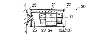
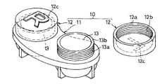
図13は、本発明が対象とするコンタクトレンズケース10の一例を示している。このコンタクトレンズケース10は、合成樹脂材料の成形品からなるもので、一つのケース本体11と、二つのキャップ体12とからなっている。ケース本体11は、同一平面上に位置し同一方向に向く一対の有底筒状部13を有し、各有底筒状部13の外周面には雄ねじ13aが形成されている。各有底筒状部13は、その開放端に軸線と直交する端面13bを有している。
【0011】
一対の同一形状のキャップ体12は、偏平な逆有底筒状をなしていて、その開放端に軸線と直交する端面12aを有しており、その内周面には、雄ねじ13aと螺合する雌ねじ12bが形成されている。本ケース10に収納するレンズは、左右で度数等の仕様が異なることがあるため、キャップ体12にはその表面(底部外面)に、左右表示12cが付されている。
【0012】
以上のコンタクトレンズケース10は、一対の有底筒状部13内に洗浄液と左右のレンズを入れた後、雄ねじ13aに雌ねじ12bを螺合させて有底筒状部13とキャップ体12により密閉空間を作ることで、その姿勢を問わず洗浄液の漏洩を防ぎ、常時レンズと洗浄液を接触させることができる。ケース本体11の有底筒状部13とキャップ体12との結合態様はねじ以外の結合態様、例えば単なる嵌め合いでもよい。
【0013】
本発明は、例えば以上のコンタクトレンズケース10のケース本体11とキャップ体12を洗浄後に分離して乾燥させる際に用いるホルダーを提供するものである。すなわち、コンタクトレンズケース10を一度使用してレンズを洗浄液で洗浄した後には、ケース本体11とキャップ体12を別々に清水(一般的に水道水)で洗浄し、雑菌に触れることがないように分離させて乾燥させることが好ましい。
【0014】
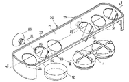
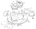
本発明は、ケース本体11の有底筒状部13の端面13bの外周縁と、キャップ体12の端面12aの外周縁のそれも一部だけに接触して保持するホルダーを提供することで、以上要求に応えるものである。図1ないし図3は、本発明の第一の実施形態を示している。このホルダー20は、合成樹脂材料の成形品からなるもので、平板状基板21を有しており、その上面周縁には、該基板21上に置いたケース10が脱落するのを防止する脱落防止突縁22が形成されている。一方、平板状基板21の下面には、その略中央部にケース本体11を保持するための一対のテーパ脚部23が垂下形成されており、このテーパ脚部23の左右に、一対のキャップ体12を保持するための各一対のテーパ脚部24が一直線上に並べて形成されている。別言すると、平板状基板21は、一対のテーパ脚部23と二対のテーパ脚部24を形成するに充分な横長矩形形状である。平板状基板21には、吸盤25に結合するための結合部26が形成されており、吸盤25を垂直面に吸着すると、平板状基板21が略水平になる。
【0015】
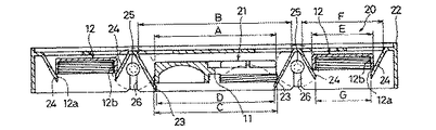
一対のテーパ脚部23は、平板状基板21から下方に向けて間隔を縮小するものである。いま、図2に示すように、ケース本体11の一対の有底筒状部13の並び方向の最大の長さをAとすると、一対のテーパ脚部23の上端の間隔BはAより十分大きい。(B>A)。また、一対の有底筒状部13の端面13b上の最大の距離をCとすると、一対のテーパ脚部23の下端の間隔DはCより小さい(C>D)。よって、有底筒状部13の開口端を下に向けたケース本体11を一対のテーパ脚部23の間に挿入すると、有底筒状部13の端面13bの外周縁とテーパ脚部23とが点接触または線接触し、これ以外の部分に接触することなく、ケース本体11を保持することができる(図2)。
【0016】
同様に、一対のテーパ脚部24は、平板状基板21から下方に向けて間隔を縮小するものである。いま、平面円形をなすキャップ体12の径(端面12aの外周縁径)をEとすると、一対のテーパ脚部24の上端の間隔FはEより十分大きい。(F>E)。また、一対のテーパ脚部24の下端の間隔GはEより小さい(E>G)。よって、開口端を下に向けたキャップ体12を一対のテーパ脚部24の間に挿入すると、キャップ体12の端面12aの外周縁とテーパ脚部24とが点接触または線接触し、これ以外の部分に接触することなく、キャップ体12を保持することができる(図2)。テーパ脚部23、24は平板状であっても、断面円弧状であってもよい。
【0017】
すなわち、一対のテーパ脚部23は、ケース本体11の有底筒状部13の端面13bの外周縁に2カ所で点または線接触して保持する本体保持部を構成し、一対のテーパ脚部24は、キャップ体12の端面12aの外周縁に2カ所で点または線接触して保持する一対のキャップ体保持部を構成する。従って、図2、図3の状態で洗浄後のケース本体11とキャップ体12を保持すれば、雑菌の付着のおそれなく、乾燥することができる。ホルダー20は適当な台の上に載置してもよく、吸盤25を用いて垂直面に吸着保持してもよい。
【0018】
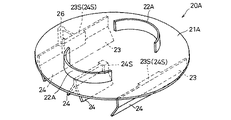
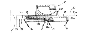
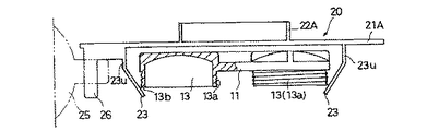
図4ないし図9は、本発明によるホルダー20Aの別の実施形態を示している。この実施形態は、平板状基板21に代えて平面円板状の基板21Aを用いた点、該基板21A上の脱落防止突縁22Aをコンタクトレンズケース10の平面形状に対応させた点、及びテーパ脚部23と一対のテーパ脚部24とを平行に並べた点が第一の実施形態と異なる。また、この実施形態では、テーパ脚部23、24の上端部に、基板21に直交する直交垂下壁23v、24vを設けており、かつ一対のテーパ脚部23(直交垂下壁23v)の壁を延長して、対をなすテーパ脚部24(直交垂下壁24v)の一方の壁としている(図8、図9)。テーパ脚部23、24には、ケース本体11とキャップ体12の挿入位置を規制するストッパ突起23s、24sが設けられている。基本的な寸法関係は、第一の実施形態と同様である。
【0019】
図5、図6では、基板21Aの上に載置するレンズ洗浄状態のケース10、一対のテーパ脚部23によって支持されるケース本体11、及び二対のテーパ脚部24によって保持されるキャップ体12を合わせて描いている。この実施形態のホルダー20も、第一の実施形態と同様に用いることができる。
【0020】
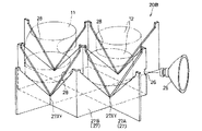
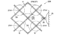
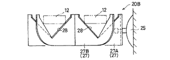
図10ないし図12は、本発明のホルダー20Bの第三の実施形態を示している。この実施形態のホルダー20Bは、複数の垂直基板27を平面視略直交させて組み合わせた構成であり、これら複数の垂直基板27中の二枚の垂直基板の交差部分27XYに、V字状溝28を形成している。より詳細には、中央の平面十字状垂直基板27Aと、周縁の平面矩形垂直基板27Bとを組み合わせ、十字状垂直基板27Aを構成する垂直基板と、矩形垂直基板27Bを構成する垂直基板との交差部分27XYに、該交差部分27XYを中心に上方に向かって間隔を拡げるV字状溝28を構成している。矩形状垂直基板27Aの一部には、吸盤25に結合するための結合部26が形成されており、吸盤25を垂直面に吸着すると、垂直基板27が略垂直になる。
【0021】
上記構成のホルダー20Bは、垂直基板27の二つの交差部分27XYの二つのV字状溝28に跨らせて、有底筒状部13の開口端を下方に向けたケース本体11を載置し、垂直基板27の一つの交差部分27XYのV字状溝28に、キャップ体12を載置する。すると、V字状溝28の縁部が、有底筒状部13の端面13bの外周縁に2カ所で点または線接触してケース本体11を保持し、かつキャップ体12の端面12aの外周縁に2カ所で点または線接触してこれを支持する。従って、洗浄後のケース本体11とキャップ体12を雑菌の付着のおそれなく乾燥することができる。ホルダー20は適当な台の上に載置してもよく、吸盤25を用いて垂直面に吸着保持してもよい。
【0022】
【発明の効果】
以上のように本発明のコンタクトレンズケースホルダーによれば、洗浄剤とレンズを一緒に保持するコンタクトケースの本体とキャップ体を、雑菌の付着のおそれなく、容易に乾燥させることができる。
【図面の簡単な説明】
【図1】本発明によるコンタクトレンズケースホルダーの第一の実施形態を示す斜視図である。
【図2】図1のII‐II線に沿う断面図である。
【図3】図1のIII‐III線に沿う断面図である。
【図4】本発明によるコンタクトレンズケースホルダーの第二の実施形態を示す、ホルダ単体の斜視図である。
【図5】同コンタクトレンズケースホルダーの使用状態の斜視図である。
【図6】図4、図5のホルダーの平面図である。
【図7】図6の正面図である。
【図8】図6のVIII‐VIII線に沿う断面図である。
【図9】図6のIX‐IX線に沿う断面図である。
【図10】本発明によるコンタクトレンズケースホルダーの第三の実施形態を示す斜視図である。
【図11】同平面図である。
【図12】図11の正面図である。
【図13】コンタクトレンズホルダーの一例の斜視図である。
【符号の説明】
10 コンタクトレンズケース
11 ケース本体
12 キャップ体
12a 端面
12b 雌ねじ
12c 左右表示
13 有底筒状部
13a 雄ねじ
13b 端面
20 20A 20B ホルダー
21 平板状基板
22 脱落防止突縁
23 テーパ脚部
24 テーパ脚部
25 吸盤
26 結合部
27 垂直基板
27A 十字状垂直基板
27B 矩形垂直基板
27XY 交差部分
28 V字状溝[0001]
【Technical field】
The present invention relates to a holder for a contact lens case.
[0002]
[Prior art and its problems]
A contact lens (hereinafter simply referred to as a lens) needs to be washed with a cleaning agent after use in order to disinfect germs attached during wearing and remove dirt. For this reason, in general, many people remove it before going to bed, put it in a lens case together with a cleaning agent, leave it overnight, and then re-attach it the next morning. The lens case is usually divided into left and right eyes (lenses) and includes a detachable case body and a cap body.
[0003]
After disposing of the cleaning agent, the used holder is washed with fresh water (generally tap water) and dried. At this time, if it is necessary to prevent the attachment of various germs as much as possible, use the holder together with the washing. The lens to be put in may be contaminated. However, since the lens case is divided into a main body and a cap body, each of which must be dried separately, there is no conventionally preferred lens case holder, that is, a holder that can be easily dried without fear of adhesion of various bacteria. Was.
[0004]
[Object of the invention]
The present invention is a holder for a contact case that holds a cleaning agent and a lens together based on the above problem awareness, and can easily dry a case body and a cap body without fear of adhesion of various bacteria. The purpose is to obtain a lens case holder.
[0005]
Summary of the Invention
The holder for holding the contact lens case according to the present invention comprises a main body of the contact lens case with the open ends of the pair of bottomed cylindrical portions facing downward, and at least two locations on the outer peripheral edges of the end surfaces of the pair of cylindrical portions. A case main body holding portion which is held in contact with a point or a line at a point or line contact at at least two places with the open end of the inverted bottomed cylindrical cap body facing downward at an outer peripheral edge of an end surface of the cylindrical portion; And a pair of cap body holding portions for holding.
[0006]
The contact lens case holder of the present invention specifically includes, for example, a flat substrate, and the case body holding portion and the pair of cap body holding portions are formed by hanging from the lower surface of the flat substrate. It can be formed by a pair of tapered legs that decrease the spacing downward.
[0007]
The pair of tapered legs of the case body holding portion and the pair of tapered legs of each of the pair of cap holding portions can be provided side by side in the same straight line, or the tapered legs of the pair of cap holding portions can be straightened. The cap holding portion taper legs aligned in a line and the pair of taper legs of the case body holding portion can be aligned in parallel.
[0008]
It is preferable that the upper surface of the flat substrate is a mounting surface on which a contact lens case containing a contact lens and a cleaning liquid is mounted, and a falling edge is formed on the mounting surface.
[0009]
As another aspect, a holder is formed by a plurality of vertical substrates combined in a substantially orthogonal manner, and a V-shape extending upward is formed at the intersection of two vertical substrates in the plurality of vertical substrates. The groove allows the case body holding portion and the pair of cap body holding portions to be formed.
[0010]
DETAILED DESCRIPTION OF THE INVENTION
FIG. 13 shows an example of the
[0011]
The pair of
[0012]
The above-mentioned
[0013]
The present invention provides a holder used when the
[0014]
The present invention provides a holder that contacts and holds only the outer peripheral edge of the
[0015]
The interval between the pair of
[0016]
Similarly, the pair of
[0017]
That is, the pair of
[0018]
4 to 9 show another embodiment of the
[0019]
5 and 6, a
[0020]
10 to 12 show a third embodiment of the
[0021]
The
[0022]
【The invention's effect】
As described above, according to the contact lens case holder of the present invention, the main body and the cap body of the contact case that holds the cleaning agent and the lens together can be easily dried without fear of the attachment of various bacteria.
[Brief description of the drawings]
FIG. 1 is a perspective view showing a first embodiment of a contact lens case holder according to the present invention.
FIG. 2 is a sectional view taken along the line II-II in FIG.
FIG. 3 is a sectional view taken along line III-III in FIG.
FIG. 4 is a perspective view of a single holder of a contact lens case holder according to a second embodiment of the present invention.
FIG. 5 is a perspective view of the use state of the contact lens case holder.
FIG. 6 is a plan view of the holder of FIGS. 4 and 5;
FIG. 7 is a front view of FIG. 6;
FIG. 8 is a sectional view taken along the line VIII-VIII in FIG. 6;
FIG. 9 is a sectional view taken along line IX-IX in FIG. 6;
FIG. 10 is a perspective view showing a third embodiment of the contact lens case holder according to the present invention.
FIG. 11 is a plan view of the same.
FIG. 12 is a front view of FIG. 11;
FIG. 13 is a perspective view of an example of a contact lens holder.
[Explanation of symbols]
DESCRIPTION OF
Claims (6)
上記ケース本体を一対の有底筒状部の開放端を下方に向けて、該一対の筒状部の端面外周縁に少なくとも2カ所で点または線接触して保持するケース本体保持部と;上記逆有底筒状キャップ体の開放端を下方に向けて該筒状部の端面外周縁に少なくとも2カ所で点または線接触して保持する一対のキャップ体保持部と;
を有することを特徴とするコンタクトレンズケースホルダー。A case body having a pair of independent bottomed cylindrical portions for separately containing the cleaning liquid and the left and right contact lenses, and a pair of flat inverted bottomed cylindrical shapes detachable from the open ends of the pair of bottomed cylindrical portions. A holder for holding a contact lens case having a cap body formed therefrom,
A case body holding portion for holding the case body in a state where the open ends of the pair of bottomed cylindrical portions face downward and at least two points or lines contact the outer peripheral edges of the end surfaces of the pair of cylindrical portions; A pair of cap holders for holding the inverted bottomed cylindrical cap in a point or line contact at least at two locations on the outer peripheral edge of the end face with the open end facing downward;
A contact lens case holder comprising:
Priority Applications (1)
| Application Number | Priority Date | Filing Date | Title |
|---|---|---|---|
| JP2003098283A JP2004298564A (en) | 2003-04-01 | 2003-04-01 | Contact lens case holder |
Applications Claiming Priority (1)
| Application Number | Priority Date | Filing Date | Title |
|---|---|---|---|
| JP2003098283A JP2004298564A (en) | 2003-04-01 | 2003-04-01 | Contact lens case holder |
Publications (2)
| Publication Number | Publication Date |
|---|---|
| JP2004298564A true JP2004298564A (en) | 2004-10-28 |
| JP2004298564A5 JP2004298564A5 (en) | 2005-10-27 |
Family
ID=33409858
Family Applications (1)
| Application Number | Title | Priority Date | Filing Date |
|---|---|---|---|
| JP2003098283A Pending JP2004298564A (en) | 2003-04-01 | 2003-04-01 | Contact lens case holder |
Country Status (1)
| Country | Link |
|---|---|
| JP (1) | JP2004298564A (en) |
Cited By (1)
| Publication number | Priority date | Publication date | Assignee | Title |
|---|---|---|---|---|
| US8468713B2 (en) | 2010-08-23 | 2013-06-25 | Karen Marie Evans | Contact lens case drying and storage rack assembly |
-
2003
- 2003-04-01 JP JP2003098283A patent/JP2004298564A/en active Pending
Cited By (1)
| Publication number | Priority date | Publication date | Assignee | Title |
|---|---|---|---|---|
| US8468713B2 (en) | 2010-08-23 | 2013-06-25 | Karen Marie Evans | Contact lens case drying and storage rack assembly |
Similar Documents
| Publication | Publication Date | Title |
|---|---|---|
| USD415295S (en) | Tealight candle holder | |
| US5297677A (en) | Sanitary toothbrush holder | |
| US6966445B1 (en) | Soap saving holder | |
| EP0437010A1 (en) | A soap having a recessed portion for receiving a piece of used soap | |
| ATE354382T1 (en) | CONTACT LENS CARE PREPARATION CONTAINING DEXPANTHENOL | |
| US20130276323A1 (en) | Contact lens case drying and storage rack assembly | |
| USD424443S (en) | Bottle support base | |
| JP2004298564A (en) | Contact lens case holder | |
| JP2006314739A (en) | Cup holder | |
| USD513701S1 (en) | Bottle | |
| PT1326570E (en) | An eye rinsing device | |
| US2038941A (en) | Tooth brush holder | |
| JP2008254771A (en) | Removable connection structure and container tray | |
| JP3112552U (en) | Contact lens case holder | |
| KR950007168B1 (en) | Structure of cup holders | |
| JP3242257U (en) | drainer cup stand | |
| JP2009178338A (en) | Cutting board | |
| CN218099848U (en) | Lens clamping cover | |
| KR200276551Y1 (en) | Glasses hanger made of luminous silicone | |
| JP4082942B2 (en) | Counter structure | |
| US8950080B2 (en) | Contact lens case drying and storage rack assembly | |
| ES1237985U (en) | Protector with built-in suction cup for tables and work surfaces (Machine-translation by Google Translate, not legally binding) | |
| KR200405694Y1 (en) | Chopping board | |
| JPS64151Y2 (en) | ||
| KR200363923Y1 (en) | Cup Holder |
Legal Events
| Date | Code | Title | Description |
|---|---|---|---|
| A521 | Written amendment |
Free format text: JAPANESE INTERMEDIATE CODE: A523 Effective date: 20050519 |
|
| A621 | Written request for application examination |
Free format text: JAPANESE INTERMEDIATE CODE: A621 Effective date: 20050519 |
|
| A711 | Notification of change in applicant |
Free format text: JAPANESE INTERMEDIATE CODE: A711 Effective date: 20050519 |
|
| A521 | Written amendment |
Free format text: JAPANESE INTERMEDIATE CODE: A821 Effective date: 20050519 |
|
| A521 | Written amendment |
Free format text: JAPANESE INTERMEDIATE CODE: A523 Effective date: 20050722 |
|
| RD02 | Notification of acceptance of power of attorney |
Free format text: JAPANESE INTERMEDIATE CODE: A7422 Effective date: 20050722 |
|
| A977 | Report on retrieval |
Free format text: JAPANESE INTERMEDIATE CODE: A971007 Effective date: 20071001 |
|
| A131 | Notification of reasons for refusal |
Free format text: JAPANESE INTERMEDIATE CODE: A131 Effective date: 20080318 |
|
| A02 | Decision of refusal |
Free format text: JAPANESE INTERMEDIATE CODE: A02 Effective date: 20080722 |