【0001】
【発明の属する技術分野】
本発明はラマン増幅器に関し,特にそれを用いた光伝送システム装置におけるファイバ,かつ,コネクタの状態をモニタする手法及びそれに伴う装置制御手法に関する。
【0002】
【従来の技術】
光伝送システムの伝送容量を向上させる手段として複数の情報を複数波長の光で伝送する,波長多重 (WDM : Wavelength Division Multiplexing) 伝送システムが注目されている。WDMシステムは,エルビウム添加ファイバ増幅器 (EDFA : Erbium‐Doped Fiber Amplifier) を採用することにより長距離大容量伝送を実現させた。
しかしながら,EDFAを用いた光伝送システムでは,大容量化,長距離化それぞれの要求に対して以下の課題に直面している。まず,大容量化の課題はEDFAの増幅帯域がCバンド (1530〜1565nm) 及びLバンド (1565〜1625nm) に制限されてしまう事である。近年エルビウム以外のドーパントを用いることにより,例えばSバンド (1460〜1530nm) で光増幅することも検討されているが,まだ実用段階ではない。もう一つの長距離化における課題は,伝送距離及び中継間隔がEDFAで発生するASEの累積に伴うSNR劣化により制限されてしまう事である。
【0003】
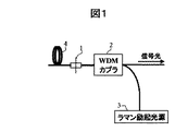
これらの問題点を解決する技術として,ラマン増幅器(10)が検討されている。ラマン増幅器(10)の構成を図1に示す。(Hiroshi NAKAMOTO, et.al, ”1.05Tbit/s WDM Transmission over 8,186km Using Distributed Raman Amplifier Repeaters”, Optical Fiber Conference 2001, Paper.TuF6参照)ラマン増幅器(10)は,ラマン励起光源(3),ファイバ(4),コネクタ(1),励起光用WDMカプラ(2)から構成される。上記の文献のラマン増幅器(10)の構成ではコネクタ(1)が記されていないが,一般的にファイバ(4)とラマン励起光源(3)は脱着可能なコネクタ(1)で接続されている。ラマン励起光源(3)をファイバ(4)に入射すると,そのうちの一部がガラス分子の光学フォノンを励起する事によりエネルギーを失い,その分だけ長い波長への光と変換される。この状態で信号光を入射すると,信号光が増幅されて出力する。このラマン増幅器(10)は,ファイバ(4)の後方からラマン励起光源(3)の光出力数百mW〜1W程度を入射させる事で実現する。このように,ラマン増幅器(10)は非線形現象を利用する為,既存の光ファイバをそのまま用いる事ができるという利点を持つ。また,伝送路中にて長い距離にわたり増幅を行うため,信号雑音比(SNR)改善可能となり,伝送距離,中継間隔を伸ばす事が可能となる。また,システムの低コスト化にも有効でありWDMシステムの応用においてメリットが大きい。
【0004】
【発明が解決しようとしている課題】
しかしながら,ラマン増幅器(10)では励起光源からの光出力が数百mW〜1W程度に達する為,その高出力な光パワーにより装置と装置の接続部のコネクタ(1)を破損するという問題が生じる。コネクタ(1)の端面は通常接続前には洗浄することが推奨されているが,充分な洗浄がされていなかった場合,洗浄しても汚れがとれなかった場合,あるいは洗浄後に汚れてしまった場合には,コネクタ(1)に汚れ(主に有機物)が付着したままとなり,この状態のままラマン増幅器(10)を立ち上げると,ラマン励起光がこのコネクタ(1)上の汚れに吸収され発熱し,コネクタ(1)接続点の温度が上昇してコネクタ(1)端面が融解する恐れがある。コネクタ(1)が融解してしまった場合にはコネクタ(1)をつけかえる為に新規の作業が必要となり,また,コネクタ(1)の付替えに伴う過剰損失も発生する。また,一般にファイバ(4)と装置の保有者あるいは装置ベンダが同一であるとは限らず,伝送路側のコネクタ(1)を破損した場合には,容易にコネクタ(1)の交換が可能とならない場合もある。
【0005】
また,高出力な光パワーの励起光源が通過するファイバ(4)が何らかの原因で急激に曲げられた場合においても励起光の入射角が変化して臨界角以上の光が放射されてしまい,その放射光がファイバ(4)を保護しているファイバジャケットにもれ,励起光が吸収され発熱し,融解する恐れもある。ファイバ(4)が融解してしまった場合にはファイバ(4)を入れ替える為に新規の作業が必要となる。また,コネクタ(1)と同様に一般にファイバ(4)と装置の保有者あるいは装置ベンダが同一であるとは限らず,容易にファイバ交換が可能とならない場合もある。
【0006】
このような問題を解決するためにoptical time−domain reflectometers(以下,OTDRと記す)という伝送路中の反射状態をモニタする測定機を用いて,装置接続前にあらかじめコネクタ(1)において異常な反射が生じていないことを測定して,汚れが付着していないことを確認する手法が考えられる。OTDRは光ファイバを時間の領域で評価する事ができ,光ファイバ内で生じる後方散乱光を測定している。後方散乱光は,レイリー散乱およびフレネル反射によって発生する。レイリー散乱は,ファイバを製造する際に発生する材料の密度などの変化から発生する。フレネルの反射は,接続点,スプライス,ファイバの端での屈折率の変化によって発生する。従って,レイリー散乱光とフレネル反射光の一部が後方散乱光としてファイバの入り口に戻ってくる。
【0007】
OTDR装置(11)内は,図2に示すような構成である。パルス発生器(9)により駆動されたOTDR光源(8)からは短パルス光が発生し,同短パルス光はファイバ(4)に入射する。ファイバ(4)におけるレイリー散乱光及びコネクタ(1)におけるフレネル反射光の一部が後方散乱光となって戻ってくる。また,同後方散乱光をフォトダイード(6)(以下PDと記す)へ導く。PD(6)からの信号は,増幅されるが,増幅後においても,検出される光は弱いパワで行うため,繰りかえし同じ測定をおこなう。パワーの損失を測定し,測定結果を波形観測モニタ(7)で観測する。
【0008】
観測される結果は,図3に示すように横軸が距離,縦軸がパワ値で表示される。入力光も後方散乱光も距離が進むと減衰していく状態となる。もし,コネクタ(1)またはファイバ(4)に異常があると,急激な屈折率変化によるフレネル反射が生じる。後方散乱光やフレネル反射光は反射点からの距離に比例した遅延時間で入射端に戻ってくる。戻ってきた光パワの時間変化を測定する事によって,それぞれのコネクタ(1)の状態を監視する事が可能になる。ラマン増幅装置の運用前にこのOTDR装置(11)を接続して異常反射の有無を測定することにより,異常反射点でのラマン励起光吸収によるコネクタ(1)端面,かつ,励起光が通過するファイバ(4)での融解,燃焼は回避可能となる。
【0009】
OTDR装置(11)を接続して異常反射の有無を測定する構成を図4に示す。しかしながら,一般にOTDR装置(11)は高価であるため,全ラマン増幅器(10)に1台ずつ設置することはシステムのトータルコストの観点から,事実上不可能であり,各増幅器毎に順次測定する方法が現実的である。
よってOTDR装置(11)は常時接続でなく,コネクタ(1)接続点でラマン増幅器(10)とOTDR装置(11)をつなぎ換えて接続する形態となる。そのような測定形態となるため,OTDR装置(11)で異常反射の有無の測定をした後,ラマン増幅器(10)につなぎ換える際にコネクタ(1)にゴミが付着する恐れがある。
さらにサイトとサイトは一般に数十km程度離れた場所にあるため,長距離伝送システムで全サイトを順次測定して汚れがないことを確認するためには,膨大な時間を必要としてしまい,装置インストール工程が長期間化してしまう問題もある。
【0010】
【課題を解決するための手段】
かかる問題に対して本発明が提供する構成は,ファイバ(4)と,前記ファイバ(4)を励起する少なくとも1台の励起光源と,前記励起光源からの出力励起光と信号光を合波する為の合波器とから構成されるラマン増幅器(10)において,前記光ファイバからの反射光を分岐するための光カプラ(5)またはサーキュレーターを前記励起光源と前記合波器の間に設け,かつ,前励起光源をパルス変調するためにパルス発生器(9)を接続し,かつ,前記光カプラ(5)またはサーキュレーターの端子に励起反射光用のフォトダイオードを設け,かつ,フォトダイオードの出力を処理する波形観測モニタ(7)を設ける装置構成とし,伝送路からの反射光をモニタすることを特徴とするラマン増幅装置である。
【0011】
また,外部に警報発生回路(12)を付ける事により,波形観測モニタ(7)からの出力値により,ファイバコネクタやファイバにおける異常反射光を検出して,異常警報を出力するラマン増幅装置を実現する。
【0012】
さらに,励起光源電源制御回路(13)を付ける事より警報発生回路(12)からの信号に応じて励起光源電源を制御するラマン増幅装置を実現する。
【0013】
【発明の実施の形態】
本発明の第1の実施例を図5を用いて説明する。図5に示す伝送システムは,励起光用WDMカプラ(2),ラマン励起光源(3),光カプラ(5),PD(6),パルス発生器(9),波形観測モニタ(7)で構成されている。本発明では,光伝送システム内で使用する,ラマン励起光源(3)をパルスに変えて,ファイバ(4)中へ光を入射させる。ファイバ(4)にて光パルスはレイリー散乱し,その一部が逆方向に伝播し,後方散乱光となって戻ってくる。戻ってきた光は,光カプラ(5)によってPD(6)へ到達する。その測定結果を波形観測モニタ(7)で観測し,伝送路からの反射光,及びコネクタ(1)での吸収を検出する。
【0014】
具体例として,励起波長1450nmのラマン励起光源(3)をパルス幅2.5μsで変調し,APD(Avalanche Photo Diode)で受光した場合の受信波形を図8に示す。横軸は励起光源からの距離,縦軸は戻り光レベルを示す。受光パワーが右下りの傾斜となるのはファイバ損失によるものである。また,コネクタ(1)における波形のギャップは,フレネル反射によるものである。Aはコネクタ(1)の清掃を充分行い接続を行った状態,Bはコネクタ(1)で吸収が存在した場合である。Bではコネクタ(1)で異常が起こったため,コネクタ(1)後では,光パワ値が1.0dB減衰している状態が観察できる。この結果から,本発明によりコネクタ(1)の異常反射と判断した場合には,警報信号を出力する制御,あるいは増幅器をシャットダウンする制御を行う事で装置内の安全性を高める事ができる。
【0015】
また,本発明では光伝送システム内で使用する,ラマン励起光源をパルス変調させて,コネクタ(1)の反射を検出しているため,サイト毎に測定器を設置する手間と順次測定する膨大な時間が減る利点がある。そのため,インストール工程の時間短縮など,OTDR装置(11)を設置しての測定より低コストで実現する事が可能となる。
また,上記の例では市中や海底に敷設したファイバ(4)をラマン増幅器(10)の利得媒質として用いる,分布増幅型ラマン増幅器の場合について述べたが,受信機または送信機内に設定された通常コイル状に巻き取られた数kmから数百kmのラマンファイバとよばれる光ファイバで構成されている集中増幅器方ラマン増幅器においても本発明は実施可能である。
【0016】
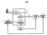
さらに本発明の第2の実施例を図6を用いて説明する。図6に示す伝送システムは,外部に警報発生回路(12)を付けているため,伝送路からの反射光のモニタした出力値の結果からコネクタ(1),ファイバ(4)における異常反射光を検出した場合には異常警報を出力し,その警報出力信号をラマン励起光源(3)の励起光源電源制御回路(13)に送り,前励起光源の電源を制御し,前励起光の出力をシャットダウンさせ,装置内の信頼性を向上させる事が可能となる。
【0017】
【発明の効果】
以上説明してきたように,本発明によれば,高価なOTDR装置(11)を必要とせず,低コストな構成で,伝送路からの反射光をモニタすることにより,コネクタ(1),ファイバ(4)における異常反射光を検出して,外部に異常警報を出力,あるいは前記励起光の出力をシャットダウンすることが実現可能となり,さらに装置内の安全性・信頼性を高めることが可能となる。
【図面の簡単な説明】
【図1】ラマン増幅器。
【図2】OTDR装置内の構成。
【図3】OTDR測定結果の例。
【図4】従来のOTDR装置を使用したコネクタ接続点の状態をモニタ手段。
【図5】本発明の第1実施例を示す構成図。
【図6】本発明の第2実施例を示す構成図。
【図7】本発明による実施例の結果。
【符号の説明】
1 コネクタ
2 励起光用WDMカプラ
3 ラマン励起光源
4 ファイバ
5 光カプラ
6 PD
7 波形観測モニタ
8 OTDR光源
9 パルス発生器
10 ラマン増幅器
11 OTDR装置
12 警報発生回路
13 励起光源電源制御回路。[0001]
TECHNICAL FIELD OF THE INVENTION
The present invention relates to a Raman amplifier, and more particularly to a method of monitoring the state of a fiber and a connector in an optical transmission system device using the same, and a device control method associated therewith.
[0002]
[Prior art]
As means for improving the transmission capacity of an optical transmission system, a wavelength division multiplexing (WDM) transmission system that transmits a plurality of pieces of information by using light of a plurality of wavelengths has attracted attention. The WDM system has realized long-distance, large-capacity transmission by employing an erbium-doped fiber amplifier (EDFA).
However, in the optical transmission system using the EDFA, the following problems are faced in response to the demands for increasing the capacity and increasing the distance. First, the problem of increasing the capacity is that the amplification band of the EDFA is limited to the C band (1530 to 1565 nm) and the L band (1565 to 1625 nm). In recent years, the use of a dopant other than erbium to amplify light in, for example, the S band (1460 to 1530 nm) has been studied, but is not yet at a practical stage. Another problem in increasing the distance is that the transmission distance and the relay interval are limited by SNR degradation due to accumulation of ASE generated in the EDFA.
[0003]
A Raman amplifier (10) has been studied as a technique for solving these problems. FIG. 1 shows the configuration of the Raman amplifier (10). (See Hiroshi NAKAMOTO, et al., "1.05 Tbit / s WDM Transmission over 8, 186 km Using Distributed Raman Amplifier Replicators," (Optical fiber optic optics, see Mann. , Fiber (4), connector (1), and WDM coupler for excitation light (2). Although the connector (1) is not described in the configuration of the Raman amplifier (10) in the above document, the fiber (4) and the Raman pumping light source (3) are generally connected by a detachable connector (1). . When the Raman excitation light source (3) is incident on the fiber (4), a part of the fiber loses energy by exciting the optical phonons of glass molecules, and is converted into light having a longer wavelength by that amount. When a signal light is incident in this state, the signal light is amplified and output. The Raman amplifier (10) is realized by allowing the optical output of the Raman pump light source (3) to be about several hundred mW to 1W from behind the fiber (4). As described above, the Raman amplifier (10) has an advantage that an existing optical fiber can be used as it is because a nonlinear phenomenon is used. Further, since amplification is performed over a long distance in the transmission path, the signal-to-noise ratio (SNR) can be improved, and the transmission distance and the relay interval can be extended. It is also effective in reducing the cost of the system, and has a great advantage in application of the WDM system.
[0004]
[Problems to be solved by the invention]
However, in the Raman amplifier (10), since the optical output from the pump light source reaches several hundred mW to 1W, the high output optical power may damage the connector (1) at the connection between the devices. . It is generally recommended that the end face of the connector (1) be cleaned before connection. However, if the cleaning has not been performed sufficiently, if the cleaning does not remove the dirt, or if the dirt is cleaned after the cleaning, In such a case, dirt (mainly organic matter) remains on the connector (1). If the Raman amplifier (10) is started in this state, the Raman excitation light is absorbed by the dirt on the connector (1). Heat may be generated, and the temperature of the connection point of the connector (1) may rise, and the end face of the connector (1) may be melted. If the connector (1) is melted, a new operation is required to replace the connector (1), and excessive loss occurs due to replacement of the connector (1). In general, the fiber (4) and the device owner or device vendor are not always the same, and if the connector (1) on the transmission line side is damaged, the connector (1) cannot be easily replaced. In some cases.
[0005]
Also, even if the fiber (4) through which the pumping light source of high output optical power passes is sharply bent for some reason, the incident angle of the pumping light changes and light exceeding the critical angle is emitted. The emitted light may leak into the fiber jacket protecting the fiber (4), and the pump light may be absorbed, generate heat, and melt. If the fiber (4) is melted, a new operation is required to replace the fiber (4). Further, similarly to the connector (1), generally, the fiber (4) and the device holder or device vendor are not always the same, and the fiber may not be easily exchanged in some cases.
[0006]
In order to solve such a problem, an optical time-domain reflectometer (hereinafter, referred to as OTDR), which is a measuring device for monitoring a reflection state in a transmission line, is used to measure abnormal reflection in the connector (1) before connecting the device. There is a method of measuring that no contamination occurs and confirming that no dirt is attached. The OTDR can evaluate an optical fiber in a time domain, and measures backscattered light generated in the optical fiber. Backscattered light is generated by Rayleigh scattering and Fresnel reflection. Rayleigh scattering is caused by a change in the density of a material generated when manufacturing a fiber. Fresnel reflections are caused by changes in the refractive index at the splice, splice, or fiber end. Therefore, a part of the Rayleigh scattered light and the Fresnel reflected light return to the fiber entrance as backscattered light.
[0007]
The inside of the OTDR device (11) has a configuration as shown in FIG. Short pulse light is generated from the OTDR light source (8) driven by the pulse generator (9), and the short pulse light is incident on the fiber (4). Part of the Rayleigh scattered light in the fiber (4) and the Fresnel reflected light in the connector (1) return as backscattered light. The backscattered light is guided to a photodiode (6) (hereinafter referred to as PD). The signal from the PD (6) is amplified, but even after amplification, the detected light is performed with weak power, so the same measurement is repeated. The power loss is measured, and the measurement result is observed with the waveform observation monitor (7).
[0008]
As shown in FIG. 3, the observed result is represented by distance on the horizontal axis and power value on the vertical axis. Both the input light and the backscattered light are attenuated as the distance increases. If there is an abnormality in the connector (1) or the fiber (4), Fresnel reflection occurs due to a sudden change in the refractive index. Backscattered light and Fresnel reflected light return to the incident end with a delay time proportional to the distance from the reflection point. By measuring the time change of the returned optical power, the state of each connector (1) can be monitored. By connecting the OTDR device (11) before the operation of the Raman amplifier and measuring the presence or absence of abnormal reflection, the end surface of the connector (1) due to absorption of Raman excitation light at the abnormal reflection point and the excitation light pass through. Melting and burning in the fiber (4) can be avoided.
[0009]
FIG. 4 shows a configuration in which the OTDR device (11) is connected to measure the presence or absence of abnormal reflection. However, since the OTDR device (11) is generally expensive, it is practically impossible to install one OTDR device for every Raman amplifier (10) from the viewpoint of the total cost of the system. The method is realistic.
Therefore, the OTDR device (11) is not always connected, and the Raman amplifier (10) and the OTDR device (11) are connected and connected at the connection point of the connector (1). Due to such a measurement form, dust may adhere to the connector (1) when the connection to the Raman amplifier (10) is performed after measuring the presence or absence of abnormal reflection by the OTDR device (11).
In addition, since sites are generally distant from each other by about several tens of kilometers, it takes an enormous amount of time to measure all sites sequentially with a long-distance transmission system and check that there is no dirt. There is also a problem that the process becomes longer.
[0010]
[Means for Solving the Problems]
In order to solve this problem, the present invention provides a fiber (4), at least one pump light source for pumping the fiber (4), and multiplexing of the pump light and the signal light output from the pump light source. An optical coupler (5) or a circulator for splitting the reflected light from the optical fiber between the pumping light source and the multiplexer. A pulse generator (9) is connected for pulse modulation of the pre-excitation light source, and a photodiode for excitation reflection light is provided at a terminal of the optical coupler (5) or the circulator, and an output of the photodiode is provided. A Raman amplifying device characterized in that it has a device configuration provided with a waveform observation monitor (7) for processing the reflected light, and monitors reflected light from a transmission line.
[0011]
Also, by attaching an external alarm generation circuit (12), a Raman amplifier that detects abnormal reflected light from the fiber connector or fiber based on the output value from the waveform observation monitor (7) and outputs an abnormal alarm is realized. I do.
[0012]
Further, by adding the excitation light source power supply control circuit (13), a Raman amplifier that controls the excitation light source power supply according to the signal from the alarm generation circuit (12) is realized.
[0013]
BEST MODE FOR CARRYING OUT THE INVENTION
A first embodiment of the present invention will be described with reference to FIG. The transmission system shown in FIG. 5 includes a WDM coupler for pumping light (2), a Raman pumping light source (3), an optical coupler (5), a PD (6), a pulse generator (9), and a waveform observation monitor (7). Have been. In the present invention, the Raman pump light source (3) used in the optical transmission system is changed into a pulse, and light is incident on the fiber (4). The light pulse undergoes Rayleigh scattering in the fiber (4), and a part of the light pulse propagates in the opposite direction and returns as backscattered light. The returned light reaches the PD (6) by the optical coupler (5). The measurement result is observed by the waveform observation monitor (7), and the reflected light from the transmission line and the absorption by the connector (1) are detected.
[0014]
As a specific example, FIG. 8 shows a reception waveform when a Raman excitation light source (3) having an excitation wavelength of 1450 nm is modulated with a pulse width of 2.5 μs and received by an APD (Avalanche Photo Diode). The horizontal axis indicates the distance from the excitation light source, and the vertical axis indicates the return light level. The slope of the received light power falling to the right is due to fiber loss. The gap of the waveform in the connector (1) is due to Fresnel reflection. A shows a state in which the connector (1) has been sufficiently cleaned and connected, and B shows a state in which absorption is present in the connector (1). In B, since an abnormality occurred in the connector (1), a state in which the optical power value is attenuated by 1.0 dB can be observed after the connector (1). From this result, when it is determined that the connector (1) is abnormally reflected according to the present invention, safety in the device can be enhanced by performing control to output an alarm signal or control to shut down the amplifier.
[0015]
Further, in the present invention, since the reflection of the connector (1) is detected by pulse-modulating the Raman excitation light source used in the optical transmission system, it takes a lot of time to install a measuring instrument for each site and to sequentially measure. There is an advantage that time is reduced. For this reason, it is possible to reduce the time required for the OTDR device (11), for example, to shorten the time required for the installation process, and to realize the measurement at a lower cost.
In the above example, the distributed amplification type Raman amplifier using the fiber (4) laid in the city or on the sea floor as a gain medium of the Raman amplifier (10) has been described. However, it is set in the receiver or the transmitter. The present invention is also applicable to a lumped amplifier-type Raman amplifier composed of an optical fiber called a Raman fiber of several km to several hundred km which is usually wound in a coil shape.
[0016]
Further, a second embodiment of the present invention will be described with reference to FIG. Since the transmission system shown in FIG. 6 has an external alarm generation circuit (12), the abnormal reflection light at the connector (1) and the fiber (4) is obtained from the result of the monitored output value of the reflection light from the transmission line. If detected, an abnormal alarm is output, and the alarm output signal is sent to the excitation light source power control circuit (13) of the Raman excitation light source (3) to control the power of the pre-excitation light source and shut down the output of the pre-excitation light. As a result, the reliability in the device can be improved.
[0017]
【The invention's effect】
As described above, according to the present invention, the connector (1) and the fiber (1) are monitored by monitoring the light reflected from the transmission line in a low-cost configuration without requiring an expensive OTDR device (11). It is possible to detect the abnormal reflected light in 4), output an abnormal alarm to the outside, or shut down the output of the excitation light, and further enhance the safety and reliability in the device.
[Brief description of the drawings]
FIG. 1 is a Raman amplifier.
FIG. 2 is a configuration inside an OTDR device.
FIG. 3 is an example of an OTDR measurement result.
FIG. 4 shows a monitor means for monitoring the state of a connector connection point using a conventional OTDR device.
FIG. 5 is a configuration diagram showing a first embodiment of the present invention.
FIG. 6 is a configuration diagram showing a second embodiment of the present invention.
FIG. 7 shows the results of an example according to the present invention.
[Explanation of symbols]
DESCRIPTION OF SYMBOLS 1 Connector 2 WDM coupler for excitation light 3 Raman excitation light source 4 Fiber 5 Optical coupler 6 PD
7 Waveform observation monitor 8 OTDR light source 9 Pulse generator 10 Raman amplifier 11 OTDR device 12 Alarm generation circuit 13 Excitation light source power supply control circuit.