JP2004286123A - Sealing structure for hydraulic cylinder - Google Patents
Sealing structure for hydraulic cylinder Download PDFInfo
- Publication number
- JP2004286123A JP2004286123A JP2003078652A JP2003078652A JP2004286123A JP 2004286123 A JP2004286123 A JP 2004286123A JP 2003078652 A JP2003078652 A JP 2003078652A JP 2003078652 A JP2003078652 A JP 2003078652A JP 2004286123 A JP2004286123 A JP 2004286123A
- Authority
- JP
- Japan
- Prior art keywords
- piston rod
- seal member
- seal
- hydraulic
- piston
- Prior art date
- Legal status (The legal status is an assumption and is not a legal conclusion. Google has not performed a legal analysis and makes no representation as to the accuracy of the status listed.)
- Pending
Links
Images


Landscapes
- Actuator (AREA)
Abstract
Description
【0001】
【発明の属する技術分野】
本発明は、一般に使用される油圧シリンダのシール構造に関する。
【0002】
【従来の技術】
例えば、H形鋼の圧延の際に用いるユニバーサル圧延機は、上下一対の水平ロールと、左右一対の垂直ロールとを備え、被圧延材のウェブを一対の水平ロールで圧下し、被圧延材のフランジを一対の垂直ロールで圧下することでH形鋼を圧延製造する装置である。このユニバーサル圧延機の一対の水平ロール及び一対の垂直ロールには、それぞれ圧下装置が連結されており、各圧下装置の作動により一対の水平ロール及び一対の垂直ロールの位置調整を行うことで、高い寸法精度のH形鋼を製造している。
【0003】
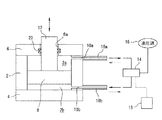
ここで、圧下装置は、一般に、油圧シリンダが使用されている。
油圧シリンダは、例えば図3に示すように、筒状のシリンダチューブ2と、このシリンダチューブ2の軸方向の両端部にそれぞれ固定したヘッドカバー4及びロッドカバー6と、シリンダチューブ2内を軸方向に摺動するピストン8と、シリンダ室2a,2bに連通する油路10a,10bと、ピストン8の一方の端面に同軸に固定され、ロッドカバー6から外部に突出しているピストンロッド12とを備えている。そして、油圧制御部13の制御信号によって制御弁14が作動することで、油圧源16で発生した作動油が作動油供給管18a,18bの一方を介してシリンダ室2a,2bの一方に供給され、それによりピストン8の移動によりピストンロッド12が矢印方向に移動することで、一対の水平ロール及び一対の垂直ロールの位置調整を行っている。
【0004】
ところで、ピストンロッド12は、ロッドカバー6に設けたロッド挿通孔6aに挿通して外部に延びており、ロッド挿通孔6aの周面とピストンロッド12の外周との間にシール部材20を配置してシール構造としている。シール部材20は、例えば、図4に示すシール部材である。このシール部材20は、ロッド挿通孔6aの周面に形成した環状溝6bに嵌入したUパッキン(以下、Uパッキン20と称する)であり、このUパッキン20を弾性変形させてピストンロッド12に密接させることで作動油が外部に漏れるのを遮断するようにしている(例えば、特許文献1。)。
【0005】
【特許文献1】
特開2002―54608号公報
【0006】
【発明が解決しようとする課題】
ところで、圧下装置として使用する油圧シリンダの作動油の圧力(使用圧力)は高圧であり、摺動部のシール構造を確実に行わないとシリンダ室の作動油が漏れやすくなり、油圧シリンダの作動特性に影響を与えてしまう。そして、油圧シリンダの作動特性が変化すると、H形鋼の品質にも影響してくる。
【0007】
しかし、図4で示したUパッキン20は、比較的短時間のうちに弾性が低下しやすく、ピストンロッド12と摺動するUパッキン20のU字状部分も早期に劣化しやすい。したがって、Uパッキン20をシール部材として使用すると、作動油の漏れ防止の信頼性が低いとともに、作動油の漏れを防止するためにシール部材を頻繁に交換しなければならず、メンテナンスコストの面で問題がある。
【0008】
そこで、本発明は上記事情に鑑みてなされたもので、作動油の漏れ防止を長期に渡って維持することで油圧シリンダの作動特性に影響を与えず、メンテナンスコストの低減化を図ることができる油圧シリンダのシール構造を提供することを目的としている。
【0009】
【課題を解決するための手段】
請求項1記載の油圧シリンダのシール構造は、シリンダチューブと、作動油の供給制御により前記シリンダチューブ内を移動するピストンと、このピストンの移動方向の一端に固定され、該ピストンの移動を直線運動として外部に伝達するピストンロッドとを備えた油圧シリンダにおいて、前記シリンダチューブの一端に固定されて前記ピストンロッドを挿通しているロッドカバーの内周部に、前記ピストンロッドの外周に密接する環状のシール部材を配置するとともに、前記ピストンロッドに接触していない前記シール部材の裏面側から該シール部材に対して所定圧のシール圧を作用させる油圧手段を設けた。
【0010】
また、請求項2記載の発明は、請求項1記載の油圧シリンダのシール構造において、前記ピストンロッドに接触していない前記シール部材の裏面側にOリングを配置し、このOリングの弾性復元力により前記シール部材を前記ピストンロッドの外周に向かう方向に押圧することで、前記Oリングを前記油圧手段を補助する補助手段とした。
【0011】
【発明の実施の形態】
以下、本発明に係る油圧シリンダのシール構造の実施形態について、図1及び図2を参照して説明する。なお、図3及び図4で示した構成と同一構成部分には、同一符号を付してその説明を省略する。
本実施形態の油圧シリンダは、図1に示すように、軸方向に重ね合わせて接合した2つのカバー部材22,24によりロッドカバー26を形成しており、シリンダチューブ2の軸方向の一端部に固定されている。このロッドカバー26に形成したロッド挿通孔26aに、ピストンロッド12が挿通している。
【0012】
また、ロッド挿通孔26aの周面には、シリンダ室2a側に第1の環状溝28が形成され、外気側に第2の環状溝30が形成されているとともに、第1の環状溝28及び第2の環状溝30との間に、第3の環状溝32が形成されている。
第2の環状溝30には、環状の第2のシール部材34が嵌入されており、ピストンロッド12に弾性変形しながら接触している。
【0013】
第3の環状溝32には、ピストンロッド12に密接する環状の第3のシール部材36と、弾性復元力が発生することで第3のシール部材36をピストンロッド12側に押圧する第3のOリング38が嵌入されている。
また、第1の環状溝28には、ピストンロッド12に接触する環状の第1のシール部材40と、この第1のシール部材40及び第1の環状溝28の内壁の間に弾性変形した状態で配置され、弾性復元力が発生することで第1のシール部材40をピストンロッド12側に押圧する第1のOリング42が嵌入されている。
【0014】
そして、ロッドカバー26には、第1の環状溝28で開口しているシール圧供給路44が形成されている。また、油圧源16で発生した作動油の一部は減圧弁46で所定圧に減圧され、シール圧Psとしてシール圧供給路44を通過して第1の環状溝28に供給される。このシール油圧Psが第1の環状溝28に供給されると、第1のシール部材40には、シール油圧Psによって背圧(ピストンロッド12に面していない側の圧力)が作用し、ピストンロッド12側に押圧され続ける。
【0015】
ここで、シール圧Psは、油圧シリンダの使用圧力が21MPaの場合、8〜12MPaに設定している。すなわち、8MPa未満の場合は、圧力不足で完全に漏れを防ぐことが出来ず、12MPaを超える場合には、ピストンロッド12との接触圧力が強すぎ、ピストンロッド12を損傷させる。なお、望ましくは、摩耗抑止のため5〜6MPaが最適である。
【0016】
なお、ロッドカバー26には、第1の環状溝28と第3の環状溝32との間の周面で一端が開口し、他端の開口部にリーク検出手段(図示せず)が接続しているリーク検出油路33が形成されている。第1の環状溝28と第3の環状溝32との間の周面に作動油が漏れていることをリーク検出手段が検知すると、第1の環状溝28に配置した第1のシール部材40のシール機能が損なわれていると判断し、新たな第1のシール部材40の交換を行う。
【0017】
上記構成の油圧シリンダでは、第1の環状溝28に嵌入した第1のシール部材40、第1のOリング42及びシール油圧Psが、シリンダ室2aの作動油が外部に漏れるのを防止するメインの漏れシール部となる。また、第3の環状溝32に嵌入した第3のシール部材36及び第3のOリング38が、サブの漏れシール部となる。そして、第2の環状溝30に嵌入した第2のシール部材34が、外部から埃や塵の侵入を防止するダストシール部となる。
【0018】
ここで、メインの漏れシール部を構成している第1のシール部材40は、ポリテトラフルオロエチレン等の合成樹脂で形成されており、軸方向に往復移動するピストンロッド12との摺動によって接触部が徐々に摩耗していく。
そして、ピストンロッド12との摺動によって第1のシール部材40が多少摩耗しても、第1のシール部材40には、第1のOリング42の弾性復元力が作用することでピストンロッド12側に押圧され、第1の環状溝28にシール油圧Psが供給されことでピストンロッド12側に押圧され続けるので、ピストンロッド12と第1のシール部材40とが密接し、シリンダ室2aの作動油が外部に漏れるのを確実に防止する。
【0019】
また、図2に示すように、ピストンロッド12との長時間の摺動によって第1のシール部材40が大幅に摩耗し(第1のシール部材40の径方向の寸法が減少した状態)、第1のOリング42が弾性変形せず第1のシール部材40を押圧しない場合であっても、第1の環状溝28に供給されているシール油圧Psは、依然として第1のシール部材40をピストンロッド12側に押圧し続けるので、ピストンロッド12と第1のシール部材40とが密接し、シリンダ室2aの作動油が外部に漏れるのを確実に防止する。
【0020】
したがって、本実施形態の油圧シリンダのシール構造によると、第1のシール部材40が多少劣化(摩耗)しても、第1のOリング42が弾性復元力により第1のシール部材40をピストンロッド12側に押圧し、且つ、第1の環状溝28にシール油圧Psが供給することで第1のシール部材40をピストンロッド12側に押圧し続けるので、ピストンロッド12と第1のシール部材40とが常に密接し、シリンダ室2aの作動油の漏れを確実に防止することができる。
【0021】
また、ピストンロッド12との摺動により第1のシール部材40が大幅に摩耗してしまい、第1のOリング42から押圧力が作用しなくても、第1の環状溝28に供給したシール油圧Psが第1のシール部材40をピストンロッド12側に押圧し続けるので、ピストンロッド12と第1のシール部材40とを常に密接させてシリンダ室2aの作動油の漏れを確実に防止することができる。したがって、本実施形態は、信頼性の高いシール構造となっている。
【0022】
また、作動油の漏れを防止する際に第1のシール部材40の許容摩耗量を大きくとることができることから、第1のシール部材40の長寿命化を図れる、つまり、第1のシール部材40を頻繁に交換しなくて済むので、メンテナンスコストの低減化も図ることができる。
さらに、作動油の漏れ防止を長期に渡って維持することが可能であることから、作動特性が安定した油圧シリンダとなり、この油圧シリンダを圧延装置の圧下装置として使用すると、高品質の圧延材を得ることができる。
【0023】
【実施例】
上述した本実施形態(本発明)のシール構造と、従来のシール構造(ピストンロッドにUパッキン(シール部材)を密接させたシール構造)のシール特性を比較したものを、図5に実験結果として示す。なお、図5の横軸は、シール部材とピストンロッドとの摺動状態を、トータルの摺動距離で示し、図5の縦軸は、外部に漏れ出た作動油の量(漏れ量)を示しているとともに、本実施形態のシール構造のシール特性を実線で示し、従来のシール構造のシール特性を破線で示している。
【0024】
図5から明らかなように、シール油圧Psが第1のシール部材40をピストンロッド12側に押圧し続ける構造とした本実施形態のシール構造は、油圧シリンダを長時間使用しても作動油の漏れがほとんど発生せず、信頼性の高いシール構造であることが理解できる。
なお、本実施形態は、圧延機の圧下装置として使用される油圧シリンダについて説明したが、本発明の要旨はこれに限定されるものではなく、他分野のアクチュエータとして使用する油圧シリンダであっても、同様の作用効果を得ることができる。
【0025】
【発明の効果】
以上説明したように、本発明の油圧シリンダのシール構造によると、ロッドカバーの内周部に、ピストンロッドの外周に密接する環状のシール部材を配置するとともに、ピストンロッドの外周に向けてシール部材に常に押圧力を付与する押圧力付与手段を設けたことから、作動油の漏れを確実に防止する信頼性の高いシール構造とすることができる。また、シール部材の許容摩耗量を大きくとることができるので、シール部材を頻繁に交換しなくて済むので、メンテナンスコストの低減化も図ることができる。
【図面の簡単な説明】
【図1】本発明の油圧シリンダのシール構造を示す軸方向の要部断面図である。
【図2】本発明を構成しているシール部材が摩耗している状態を示す図である。
【図3】油圧シリンダの全体構成を示す図である。
【図4】油圧シリンダにおいて従来使用していたシール部材を示す図である。
【図5】本発明のシール構造と従来のシール構造のシール特性を比較したグラフである。
【符号の説明】
2 シリンダチューブ
2a,2b シリンダ室
12 ピストンロッド
13 油圧制御部
16 油圧源
26 ロッドカバー
26a ロッド挿通孔
28 環状溝
40 シール部材
42 Oリング
44 シール圧供給路
46 減圧弁
Ps シール圧[0001]
TECHNICAL FIELD OF THE INVENTION
The present invention relates to a generally used hydraulic cylinder seal structure.
[0002]
[Prior art]
For example, a universal rolling mill used for rolling an H-section steel includes a pair of upper and lower horizontal rolls and a pair of left and right vertical rolls, and rolls a web of a material to be rolled down with a pair of horizontal rolls to form a material to be rolled. This device rolls and manufactures H-section steel by rolling down the flange with a pair of vertical rolls. A pair of horizontal rolls and a pair of vertical rolls of this universal rolling mill are each connected with a pressing device, and the operation of each pressing device adjusts the position of the pair of horizontal rolls and the pair of vertical rolls, thereby increasing the height. Manufactures H-beams with dimensional accuracy.
[0003]
Here, a hydraulic cylinder is generally used as the screw-down device.
As shown in FIG. 3, for example, the hydraulic cylinder includes a
[0004]
Incidentally, the
[0005]
[Patent Document 1]
Japanese Patent Application Laid-Open No. 2002-54608
[Problems to be solved by the invention]
By the way, the pressure (operating pressure) of the hydraulic oil of the hydraulic cylinder used as the pressure reduction device is high, and if the sealing structure of the sliding part is not securely performed, the hydraulic oil in the cylinder chamber will leak easily, and the operating characteristics of the hydraulic cylinder Will be affected. When the operating characteristics of the hydraulic cylinder change, the quality of the H-section steel is also affected.
[0007]
However, the elasticity of the
[0008]
Therefore, the present invention has been made in view of the above circumstances, and by maintaining leakage prevention of hydraulic oil for a long period of time, it is possible to reduce the maintenance cost without affecting the operation characteristics of the hydraulic cylinder. An object of the present invention is to provide a seal structure for a hydraulic cylinder.
[0009]
[Means for Solving the Problems]
The seal structure for a hydraulic cylinder according to claim 1, wherein the cylinder tube, a piston that moves in the cylinder tube by controlling the supply of hydraulic oil, and one end in the moving direction of the piston are fixed to move the piston linearly. A hydraulic cylinder having a piston rod that transmits the piston rod to the outside, an inner peripheral portion of a rod cover fixed to one end of the cylinder tube and through which the piston rod is inserted, and an annular ring that is in close contact with the outer periphery of the piston rod. Hydraulic means for disposing a sealing member and applying a predetermined sealing pressure to the sealing member from the back side of the sealing member that is not in contact with the piston rod is provided.
[0010]
According to a second aspect of the present invention, in the seal structure for a hydraulic cylinder according to the first aspect, an O-ring is disposed on a back surface side of the seal member that is not in contact with the piston rod, and an elastic restoring force of the O-ring is provided. By pressing the seal member in a direction toward the outer periphery of the piston rod, the O-ring serves as auxiliary means for assisting the hydraulic means.
[0011]
BEST MODE FOR CARRYING OUT THE INVENTION
Hereinafter, an embodiment of a seal structure for a hydraulic cylinder according to the present invention will be described with reference to FIGS. The same components as those shown in FIGS. 3 and 4 are denoted by the same reference numerals, and description thereof will be omitted.
In the hydraulic cylinder of the present embodiment, as shown in FIG. 1, a
[0012]
In addition, a first
An annular
[0013]
The third
The first
[0014]
In the
[0015]
Here, the seal pressure Ps is set to 8 to 12 MPa when the operating pressure of the hydraulic cylinder is 21 MPa. In other words, when the pressure is less than 8 MPa, the leakage cannot be completely prevented due to insufficient pressure. When the pressure exceeds 12 MPa, the contact pressure with the
[0016]
One end of the
[0017]
In the hydraulic cylinder having the above-described configuration, the
[0018]
Here, the
Then, even if the
[0019]
Further, as shown in FIG. 2, the
[0020]
Therefore, according to the seal structure of the hydraulic cylinder of the present embodiment, even if the
[0021]
In addition, even if the
[0022]
Further, since the allowable wear amount of the
Furthermore, since it is possible to maintain the prevention of hydraulic oil leakage for a long period of time, a hydraulic cylinder with stable operating characteristics is used.If this hydraulic cylinder is used as a rolling device of a rolling mill, high quality rolled material can be obtained. Obtainable.
[0023]
【Example】
FIG. 5 shows a comparison between the seal characteristics of the above-described embodiment (the present invention) and the seal characteristics of a conventional seal structure (a seal structure in which a U packing (seal member) is closely attached to a piston rod). Show. The horizontal axis in FIG. 5 indicates the sliding state of the seal member and the piston rod by the total sliding distance, and the vertical axis in FIG. 5 indicates the amount of hydraulic oil leaked to the outside (leakage amount). In addition, the seal characteristics of the seal structure of the present embodiment are indicated by solid lines, and the seal characteristics of the conventional seal structure are indicated by broken lines.
[0024]
As is clear from FIG. 5, the seal structure according to the present embodiment in which the seal oil pressure Ps keeps pressing the
In the present embodiment, a hydraulic cylinder used as a rolling device of a rolling mill has been described. However, the gist of the present invention is not limited to this, and a hydraulic cylinder used as an actuator in another field may be used. The same operation and effect can be obtained.
[0025]
【The invention's effect】
As described above, according to the hydraulic cylinder seal structure of the present invention, the annular seal member that is in close contact with the outer periphery of the piston rod is disposed on the inner peripheral portion of the rod cover, and the seal member is moved toward the outer periphery of the piston rod. Since the pressing force applying means for constantly applying the pressing force is provided, a highly reliable seal structure that reliably prevents the leakage of the hydraulic oil can be provided. Further, since the allowable wear amount of the seal member can be increased, the seal member does not need to be replaced frequently, so that the maintenance cost can be reduced.
[Brief description of the drawings]
FIG. 1 is a sectional view of a principal part in an axial direction showing a seal structure of a hydraulic cylinder of the present invention.
FIG. 2 is a view showing a state in which a seal member constituting the present invention is worn.
FIG. 3 is a diagram showing an overall configuration of a hydraulic cylinder.
FIG. 4 is a view showing a seal member conventionally used in a hydraulic cylinder.
FIG. 5 is a graph comparing the seal characteristics of the seal structure of the present invention and the conventional seal structure.
[Explanation of symbols]
2
Claims (2)
前記シリンダチューブの一端に固定されて前記ピストンロッドを挿通しているロッドカバーの内周部に、前記ピストンロッドの外周に密接する環状のシール部材を配置するとともに、前記ピストンロッドに接触していない前記シール部材の裏面側から該シール部材に対して所定圧のシール圧を作用させる油圧手段を設けたことを特徴とする油圧シリンダのシール構造。A hydraulic system comprising a cylinder tube, a piston that moves in the cylinder tube by supply control of hydraulic oil, and a piston rod that is fixed to one end of the piston in the movement direction and that transmits the movement of the piston to the outside as linear motion. In the cylinder,
An annular seal member that is in close contact with the outer periphery of the piston rod is disposed on the inner peripheral portion of the rod cover that is fixed to one end of the cylinder tube and that penetrates the piston rod, and that is not in contact with the piston rod. A seal structure for a hydraulic cylinder, wherein a hydraulic means for applying a predetermined sealing pressure to the seal member from the back side of the seal member is provided.
Priority Applications (1)
| Application Number | Priority Date | Filing Date | Title |
|---|---|---|---|
| JP2003078652A JP2004286123A (en) | 2003-03-20 | 2003-03-20 | Sealing structure for hydraulic cylinder |
Applications Claiming Priority (1)
| Application Number | Priority Date | Filing Date | Title |
|---|---|---|---|
| JP2003078652A JP2004286123A (en) | 2003-03-20 | 2003-03-20 | Sealing structure for hydraulic cylinder |
Publications (1)
| Publication Number | Publication Date |
|---|---|
| JP2004286123A true JP2004286123A (en) | 2004-10-14 |
Family
ID=33293073
Family Applications (1)
| Application Number | Title | Priority Date | Filing Date |
|---|---|---|---|
| JP2003078652A Pending JP2004286123A (en) | 2003-03-20 | 2003-03-20 | Sealing structure for hydraulic cylinder |
Country Status (1)
| Country | Link |
|---|---|
| JP (1) | JP2004286123A (en) |
Citations (3)
| Publication number | Priority date | Publication date | Assignee | Title |
|---|---|---|---|---|
| JPS62104004U (en) * | 1985-12-20 | 1987-07-02 | ||
| JPS6487976A (en) * | 1987-09-30 | 1989-04-03 | Nihon Valqua Kogyo Kk | Seal device |
| JP2002054608A (en) * | 2000-08-08 | 2002-02-20 | Hitachi Constr Mach Co Ltd | Hydraulic cylinder, and hydraulic cylinder drive unit |
-
2003
- 2003-03-20 JP JP2003078652A patent/JP2004286123A/en active Pending
Patent Citations (3)
| Publication number | Priority date | Publication date | Assignee | Title |
|---|---|---|---|---|
| JPS62104004U (en) * | 1985-12-20 | 1987-07-02 | ||
| JPS6487976A (en) * | 1987-09-30 | 1989-04-03 | Nihon Valqua Kogyo Kk | Seal device |
| JP2002054608A (en) * | 2000-08-08 | 2002-02-20 | Hitachi Constr Mach Co Ltd | Hydraulic cylinder, and hydraulic cylinder drive unit |
Similar Documents
| Publication | Publication Date | Title |
|---|---|---|
| RU2361140C2 (en) | Lubricant-free stem sealing system and method of sealing stem by said system | |
| JPS60227062A (en) | High pressure packing | |
| JP4421207B2 (en) | Sealing device | |
| US20140145403A1 (en) | Seal Arrangement for Sealing a Reciprocating Piston Rod of a Piston Compressor | |
| JP2007132497A (en) | Sealing device | |
| JP2008506082A (en) | Sealed arrangement | |
| JP2007139055A (en) | Sealing device and sealing structure | |
| JP4537001B2 (en) | Seal device for roll bearings with radial displacement compensation mechanism | |
| CN102588610B (en) | Hydraulic cylinder with sealing follow-up device | |
| US6173960B1 (en) | Rod seal apparatus for cylinder assembly | |
| JP2004286123A (en) | Sealing structure for hydraulic cylinder | |
| JP2007132498A (en) | Sealing device for carbon dioxide seal | |
| JP2006521506A (en) | Sealing device | |
| WO2019146459A1 (en) | Fluid leakage detector and reciprocating hydraulic device | |
| US20080023893A1 (en) | Hermetically Sealing Device | |
| JP2003042301A (en) | Valve stem seal | |
| JP4882126B2 (en) | Piston / cylinder unit | |
| US20070278747A1 (en) | Sealing Device | |
| JP2012097829A (en) | Bellows type accumulator | |
| JP2012215188A (en) | Sealing structure | |
| JP2013044428A (en) | Spring with fluid | |
| JP4578158B2 (en) | Clutch piston for fluid transmission | |
| JP2009270679A (en) | Sealing structure and sealing device | |
| JP2006505408A (en) | Connection block for hydraulic supply conduits of hydrostatic bearings in oil film bearings | |
| JP3609634B2 (en) | Cylinder device |
Legal Events
| Date | Code | Title | Description |
|---|---|---|---|
| A621 | Written request for application examination |
Free format text: JAPANESE INTERMEDIATE CODE: A621 Effective date: 20060215 |
|
| A131 | Notification of reasons for refusal |
Free format text: JAPANESE INTERMEDIATE CODE: A131 Effective date: 20070320 |
|
| A977 | Report on retrieval |
Free format text: JAPANESE INTERMEDIATE CODE: A971007 Effective date: 20070326 |
|
| A521 | Written amendment |
Free format text: JAPANESE INTERMEDIATE CODE: A523 Effective date: 20070515 |
|
| A02 | Decision of refusal |
Free format text: JAPANESE INTERMEDIATE CODE: A02 Effective date: 20070731 |