JP2004283871A - Method for manufacturing plastic structural body having micropore part and plastic structural body having micropore part made by the same method - Google Patents
Method for manufacturing plastic structural body having micropore part and plastic structural body having micropore part made by the same method Download PDFInfo
- Publication number
- JP2004283871A JP2004283871A JP2003079607A JP2003079607A JP2004283871A JP 2004283871 A JP2004283871 A JP 2004283871A JP 2003079607 A JP2003079607 A JP 2003079607A JP 2003079607 A JP2003079607 A JP 2003079607A JP 2004283871 A JP2004283871 A JP 2004283871A
- Authority
- JP
- Japan
- Prior art keywords
- hole
- plastic
- laser
- plastic structure
- function
- Prior art date
- Legal status (The legal status is an assumption and is not a legal conclusion. Google has not performed a legal analysis and makes no representation as to the accuracy of the status listed.)
- Pending
Links
Images


Abstract
Description
【0001】
【発明の属する技術分野】
本発明は、微小孔部を有するプラスチック構造体の製造方法及び該製造方法による微小孔部を有するプラスチック構造体に関するものである。
【0002】
【従来技術】
近年、プラスチック部品の高機能化、高性能化の要求が高くなってきている。それらの要求に対して、プラスチック材料自身をポリマーアロイ化したり複合化したりする材料面での技術対応と、要求機能に合わせて機能部位を付加する加工面での技術対応の二つの取り組みが行われている。プラスチック部品の表面の高機能化・高性能化は、表面の濡れ性、接着性、吸着性、制電性、水分やガスに対するバリアー性、表面硬さ、光反射性、光散乱性、光透過性などの制御の必要性から、材料・加工両面から色々な技術的な取り組みがされてきている。例えば、プラスチック部品に、微細孔の形成によって、フィルター、メンブレン、セパレータなどの機能を付加する際には、主に延伸、抽出、相分離などの方法が利用されている。
【0003】
一方、レーザー光源に関する技術進歩は著しく、特に、パルスレーザーは、ナノ(10−9)秒からピコ(10−12)秒と超短パルス化が進み、更に最近では、チタン・サファイア結晶などをレーザー媒質とするフェムト(10−15)秒パルスレーザーなどが開発されてきている。ピコ秒やフェムト秒などの超短パルスレーザーシステムは、通常のレーザーの持つ、指向性、空間的・時間的コヒーレンスなどの特徴に加えて、パルス幅が極めて狭く、同じ平均出力でも単位時間・単位空間当りの電場強度が極めて高いことから、物質中に照射して高い電場強度を利用して誘起構造を形成させる試みが、無機ガラス材料を主な対象物として行われてきている。
【0004】
なお、従来、高分子材料(ポリエチレンテレフタレートなど)からなるフィルムに、レーザー光を照射して穿孔加工を行う方法が提案されている(特許文献1参照)。
【0005】
【特許文献1】
特開平10−118569号公報
【0006】
【発明が解決しようとする課題】
しかしながら、前記特開平10−118569号公報に記載のレーザーを用いた微細粒子加工分級用フィルターの製造方法では、超短パルスレーザーの特有の効果が発揮されておらず、プラスチックに、微小径の孔部(特に、最小の径又は幅が200μm以下である貫通孔及び/又は陥没孔からなる微小孔部)を形成することができない。
【0007】
従って、本発明の課題は、プラスチックに、微小径の孔部を容易に形成することができる微小孔部を有するプラスチック構造体の製造方法及び該製造方法による微小孔部を有するプラスチック構造体を提供することにある。
本発明の他の課題は、さらに、マスクが不要であり、しかも、優れた生産性で微小な貫通孔及び/又は陥没孔を形成することができる微小孔部を有するプラスチック構造体の製造方法及び該製造方法による微小孔部を有するプラスチック構造体を提供することにある。
【0008】
【課題を解決するための手段】
本発明者らは、上記課題を解決するため鋭意検討した結果、プラスチックフィルムに、パルス幅が10−9秒以下で且つ波長が可視光領域の超短パルスのレーザーを照射すると、多光子吸収が生じることにより、プラスチックフィルムに精密な微小孔部を形成することができることを見出した。本発明は、これらの知見に基づいて完成されたものである。
【0009】
すなわち、本発明は、孔部として、最小の径又は幅が200μm以下である貫通孔及び/又は陥没孔を有するプラスチック構造体の製造方法であって、前記孔部を、多光子吸収過程を利用したレーザー加工により形成することを特徴とする微小孔部を有するプラスチック構造体の製造方法を提供する。
【0010】
本発明の微小孔部を有するプラスチック構造体の製造方法では、孔部を形成する前の被加工プラスチック基材としては、プラスチックシート又はフィルムを好適に用いることができる。
【0011】
微小孔部を有するプラスチック構造体としては、微小孔部を有するプラスチック構造体が、貫通孔を有し、且つフィルター機能、メンブレン機能、セパレータ機能、霧化機能、ガス拡散化機能、ノズル機能、または流路調整機能を有していることが好ましい。
【0012】
多光子吸収過程を利用したレーザー加工としては、パルス幅が10−9秒以下の超短パルスのレーザーを用いたレーザー加工であってもよく、該パルス幅が10−9秒以下の超短パルスのレーザーとしては、紫外線波長領域〜近赤外線波長領域の波長を有する超短パルスのレーザーであってもよい。このようなパルス幅が10−9秒以下の超短パルスのレーザーは、多光束干渉で照射することができる。また、パルス幅が10−9秒以下の超短パルスのレーザーを、該超短パルスのレーザーの照射方向に対して垂直な方向に且つプラスチック表面に対して平行な方向に、超短パルスのレーザーの焦点を移動させながら照射することが好ましい。
【0013】
なお、孔部を形成する前の被加工プラスチック基材は、素材としてフッ素系樹脂またはオレフィン系樹脂を含有していることが好ましく、表面及び/又は内部に、無機微粒子を含有していてもよい。
【0014】
また、本発明は、孔部として、最小の径又は幅が200μm以下である貫通孔及び/又は陥没孔を有するプラスチック構造体であって、前記孔部が、前記微小孔部を有するプラスチック構造体の製造方法により形成されていることを特徴とする微小孔部を有するプラスチック構造体を提供する。
【0015】
【発明の実施の形態】
以下、本発明の実施の形態を、必要に応じて図面を参照しつつ説明する。なお、同一の部位又は部材には同一の符号を付している場合がある。
(微小孔部を有するプラスチック構造体)
本発明の微小孔部を有するプラスチック構造体は、孔部として、最小の径又は幅が200μm以下である微小孔部を有するプラスチック構造体であり、前記孔部が、多光子吸収過程を利用したレーザー加工により形成されている。このような微小孔部(単に「孔部」と称する場合がある)としては、一方の表面から他方の表面に貫通している形状の貫通孔、表面から内部に陥没している形状の陥没孔のいずれであってもよく、貫通孔および陥没孔が組み合わせられていてもよい。すなわち、微小孔部を有するプラスチック構造体は、孔部として、最小の径又は幅が200μm以下である貫通孔及び/又は陥没孔を有することができる。
【0016】
このような微小孔部を有するプラスチック構造体としては、例えば、図1〜4に示されるような微小貫通孔や微小陥没孔を有するプラスチック構造体が挙げられる。図1〜2は、それぞれ、微小貫通孔を有するプラスチック構造体の例を模式的に示す概略鳥瞰図である。具体的には、図1(a)は、微小貫通孔を有するプラスチック構造体の一例を模式的に示す概略鳥瞰図であり、図1(b)は、図1(a)におけるX1−X1´線における断面図である。また、図2(a)は、微小貫通孔を有するプラスチック構造体の他の例を模式的に示す概略鳥瞰図であり、図2(b)は、図2(a)におけるX2−X2´線における断面図である。図1の微小貫通孔を有するプラスチック構造体は、プラスチックフィルム1の一方の表面から他方の表面に貫通して形成された貫通孔2aを複数個有している。また、図2の微小貫通孔を有するプラスチック構造体は、プラスチックフィルム1の一方の表面から他方の表面に貫通して形成された貫通孔2bを複数個有している。具体的には、貫通孔2aは、円筒状の形状を有している。貫通孔2bは、前記円筒状の貫通孔2aが複数連結した形状又はこれに類似する形状を有している。従って、貫通孔2bは、短径(幅)は微小であるが、微小ではない長径を有する構造の貫通孔となっている。
【0017】
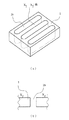
また、図3〜4は、それぞれ、微小陥没孔を有するプラスチック構造体の例を模式的に示す概略鳥瞰図である。具体的には、図3(a)は、微小陥没孔を有するプラスチック構造体の一例を模式的に示す概略鳥瞰図であり、図3(b)は、図3(a)におけるX3−X3´線における断面図である。また、図4(a)は、微小陥没孔を有するプラスチック構造体の他の例を模式的に示す概略鳥瞰図であり、図4(b)は、図4(a)におけるX4−X4´線における断面図である。図3の微小陥没孔を有するプラスチック構造体は、プラスチックフィルム1の表面に、該プラスチックフィルム1の表面から内部に陥没して形成された陥没孔(凹部)2cを複数個有している。また、図4の微小陥没孔を有するプラスチック構造体は、プラスチックフィルム1の表面から内部に陥没して形成された陥没孔(凹部)2dを複数個有している。具体的には、陥没孔2cの断面は、略半円、略半楕円又は略三角形(なお、図3では、略半円または略半楕円として例示している)の形状を有することができ、陥没孔2dは、前記断面形状の陥没孔2cで切り込まれたような形状又はこれに類似する形状を有している。従って、陥没孔2dは、短径(幅)は微小であるが、微小ではない長径を有する構造(溝状の構造)の陥没孔となっており、その断面形状は、前記陥没孔2cの断面形状(例えば、略半円、略半楕円、略三角形など)と同様の形状を有することができる。
【0018】
このように微小孔部を有するプラスチック構造体として、微小貫通孔2aや微小陥没孔2c等のような、プラスチック表面の形状が円形状となっている貫通孔や陥没孔(「単独孔部」と称する場合がある)が形成されたプラスチックや、微小貫通孔2bや微小陥没孔2d等のような、前記単独孔部が連結された形状又はこれに類似する形状の貫通孔や陥没孔(「連結孔部」と称する場合がある)が形成されたプラスチックを形成することができる。
【0019】
前記微小孔部(微小貫通孔2a,2bや、微小陥没孔2c,2d)の径は、最小の径又は幅が200μm以下であればよく、例えば、0.05〜200μm(好ましくは0.05〜100μm、さらに好ましくは0.5〜50μm)の範囲から選択することができる。微小孔部が単独孔部である場合は、その径としては、直径(又は平均径)を意味しており、連結孔部である場合は、径としては幅を意味している。また、微小孔部の径は、プラスチック表面(又は該表面と同一の面)における径を意味している。
【0020】
なお、微小孔部が、連結孔部の場合のように、長径と短径とを有するような形状を有している場合、その径としては、短径が200μm以下であればよく、長径の長さは特に制限されない。具体的には、微小孔部の径としては、例えば、短径が0.05〜200μmであり、長径が0.05μm以上(例えば、0.05〜100000μm)であってもよい。また、好ましい微小孔部の径としては、短径が0.05〜100μmであり且つ長径が0.1μm以上(例えば、0.1〜5000μm)であり、さらには、短径が0.5〜50μmであり且つ長径が0.1〜1000μmであることが好ましい。
【0021】
特に、微小孔部が、貫通していない場合(微小陥没孔の場合)、短径が0.05〜200μmで、長径が基材の端から端までのスリット溝状の陥没孔であってもよい。
【0022】
なお、微小孔部が、微小陥没孔(凹部)の場合、微小陥没孔の深さは、特に制限されないが、孔部を形成する前の被加工プラスチック基材(プラスチック基材)の厚みなどに応じて適宜選択することができ、例えば、0.1μm以上(例えば、0.1〜10μm、好ましくは0.5〜8μm)の範囲から選択することができる。
【0023】
また、微小孔部のプラスチック構造体の表面での形状としては、特に制限されず、不定形であってもよいが、例えば、マクロ的又は全体的な観点から、円形類似形状(円類似形状や楕円類似形状など)ないし四角形類似形状(正方形類似形状や長方形類似形状など)であってもよい。従って、微小孔部のプラスチック構造体表面での形状は、ミクロ的な観点からは、例えば、円形類似形状の円周がギザギザ状、波状、鋸状など曲線状であってもよく、また、四角形類似形状の長辺が直線ではなく、ギザギザ状、波状、鋸状など曲線状や折れ曲がり線状であってもよい。
【0024】
微小孔部を有するプラスチック構造体としては、微小孔部を、1つのみ有していてもよく、図1〜4で示されるように複数有していてもよい。微小孔部を複数有する場合、隣り合った孔部間の間隔は、前記最小の径又は幅と同じかそれ以上であることが好ましい。隣り合った孔部間の間隔は、一定であっても、一定でなくてもよい。なお、隣り合った孔部間の間隔としては、孔部が単独孔部である場合、プラスチック表面の円形状の中心間距離を意味し、孔部が連結孔部である場合、プラスチック表面の幅方向における中心間距離を意味することができる。
【0025】
(微小孔部を有するプラスチック構造体の形成)
本発明の微小孔部を有するプラスチック構造体は、多光子吸収過程を利用したレーザー加工により形成することができる。多光子吸収過程を利用することにより、使用するレーザー光の波長が、孔部を形成する前の被加工プラスチック基材の素材(ポリマー成分)による吸収波長よりも長くても、前記被加工プラスチック基材に、最小の径又は幅が200μm以下である微小孔部を形成する加工を行うことができる。すなわち、多光子吸収過程を利用したレーザー加工により、微細加工を効率よく、しかも優れた精度で行うことができる。
【0026】
なお、多光子吸収過程を利用したレーザー加工とは、高密度の光子が存在する場合に、複数の光子が物質に同時に吸収され、本来、その1光子のエネルギーでは生じ得なかった現象を利用する加工を意味している。また、非線形現象を利用した加工であるので、光を用いているにもかかわらず、照射波長の回折限界を超える加工も可能である。
【0027】
このような多光子吸収過程を利用したレーザー加工方法としては、レーザーを照射して加工する際に、多光子吸収過程を利用して加工する方法であれば特に制限されず、例えば、パルス幅が10−9秒以下の超短パルスのレーザー(「超短パルスレーザー」又は「レーザー」と称する場合がある)を用いたレーザー加工方法を好適に採用することができる。このような超短パルスレーザーとしては、チタン・サファイア結晶を媒質とするレーザーや色素レーザーを再生・増幅して得られたパルス幅が10−9秒以下のパルスレーザー、エキシマレーザーやYAGレーザー(Nd−YAGレーザー等)の倍波によるパルス幅が10−9秒以下のパルスレーザーなどを用いることができ、特に、チタン・サファイア結晶を媒質とするレーザーや色素レーザーを再生・増幅して得られたパルス幅が10−12秒〜10−15秒のフェムト秒のオーダーのパルスレーザー(フェムト秒パルスレーザー)を好適に用いることができる。もちろん、超短パルスレーザーにおけるパルス幅は、10−9秒以下であれば特に制限されず、例えば、10−9秒から10−12秒のピコ秒オーダーや、10−12秒から10−15秒のフェムト秒のオーダー(好ましくは10−12秒から10−15秒のフェムト秒のオーダー)であり、通常は、100フェムト秒(10−13秒)程度である。このようなチタン・サファイア結晶を媒質とするレーザーや色素レーザーを再生・増幅して得られたパルス幅が10−9秒以下のパルスレーザーや、エキシマレーザーやYAGレーザー(Nd−YAGレーザー等)の倍波によるパルス幅が10−9秒以下のパルスレーザーなどの超短パルスレーザーを用いると、パルスエネルギーが高いので、多光子吸収過程を利用したレーザー加工を行うことができ、その尖塔のパワーにより波長より狭い幅の微細加工を行うことができるようになる。従って、超短パルスレーザーを用いて多光子吸収過程を利用したレーザー加工により、最小の径又は幅が200μm以下である微小孔部[特に、短径が0.05〜200μmであり且つ長径が0.05μm以上(例えば、0.05〜100000μm)である微小孔部(なかでも、微小貫通孔)]を形成することができるようになる。なお、長径が長い場合には直線状でなく、曲線、折れ曲がり線等の任意な形状であっても良い。
【0028】
超短パルスレーザーの波長は、特に制限されず、多光子吸収過程を利用しているので、被加工プラスチック基材の樹脂成分の吸収波長(吸収のピーク波長又はその領域)よりも長い波長であってもよく、被加工プラスチック基材の樹脂成分の種類又はその吸収波長[吸収のピーク波長(特に、吸収のメインピーク波長)又はその領域]に応じて適宜選択することができる。具体的には、超短パルスレーザーの波長としては、例えば、紫外線領域〜近赤外線領域の領域内の波長であってもよく、従って、200nmから1000nmの範囲内から適宜選択することができる。なお、超短パルスレーザーの波長としては、被加工プラスチック基材の樹脂成分の吸収波長(吸収のピーク波長)の倍波(2倍波、3倍波など)となる波長であることが好ましい。
【0029】
また、超短パルスレーザーの繰り返しとしては、1Hzから100MHzの範囲で、通常は10Hzから500kHz程度である。
【0030】
被加工プラスチック基材に対して、内部における単位体積当たりに照射されるエネルギーは、超短パルスレーザーの照射エネルギー、被加工プラスチック基材に照射する際に用いられる対物レンズの開口数(光源の絞り込み)、被加工プラスチック基材への照射位置又は焦点の深さ、レーザーの焦点の移動速度などに応じて適宜決めることができる。
【0031】
本発明では、超短パルスレーザーの平均出力又は照射エネルギーとしては、特に制限されず、目的とする微小孔部(特に微小貫通孔)の大きさや形状等に応じて適宜選択することができ、例えば、10000mW以下(例えば、1〜1000mW)、好ましくは5〜500mW、さらに好ましくは10〜300mW程度の範囲から選択することができる。
【0032】
また、超短パルスレーザーの照射スポット径としては、特に制限されず、目的の微小孔部の大きさやその形状、レンズの大きさや開口数又は倍率などに応じて適宜選択することができ、例えば、0.1〜10μm程度の範囲から選択することができる。
【0033】
なお、レーザーの光線の焦点を絞って合わせるためにレンズを用いることができる。すなわち、レーザーの焦点を絞って合わせる必要が無い場合は、レンズを用いる必要はない。このようなレンズの開口数(NA)は、特に制限されず、対物レンズの倍率に応じて変更することができ、通常は、倍率としては2.5〜100倍、開口数としては0.05〜0.95程度の範囲から選択される。
【0034】
多光子吸収過程を利用したレーザー加工により、微小孔部を有するプラスチック構造体を製造する方法の一例として、パルス幅が10−9秒以下の超短パルスのレーザーを用いてレーザー加工する方法の例を下記に示すが、もちろん、このレーザー加工方法に限定されない。パルス幅が10−9秒以下の超短パルスのレーザーを用いたレーザー加工方法としては、例えば、図5で示されているように、孔部を形成する前の被加工プラスチック基材の表面及び/又は内部に、パルス幅が10−9秒以下の超短パルスのレーザー(超短パルスレーザー)を照射することにより、被加工プラスチック基材に最小の径又は幅が200μm以下である貫通孔及び/又は陥没孔を形成する方法が挙げられる。図5は、微小孔部を有するプラスチック構造体の製造方法の一例を示す概略鳥瞰図である。図5において、1はプラスチックフィルム、1aはプラスチックフィルム1の上面(表面)、1bはプラスチックフィルム1の底面(裏面)、Tはプラスチックフィルム1の厚さ、3はパルス幅が10−9秒以下である超短パルスレーザー、4はレンズ、5はレーザー3の焦点である。また、6はレーザー3の照射方向であり、7はレーザー3の焦点5の移動方向である。
【0035】
また、81,82,・・・,8n(nは1以上の整数である)はそれぞれレーザー3の焦点5をライン状に移動させる際のラインである[以下、ライン(81,82,・・・,8n)をライン8として総称する場合がある]。従って、ライン8は、焦点5の移動方向7と平行又は同一の方向に延びている。ライン8は、焦点5をライン状に移動させる際のラインであるので、焦点5がライン状に移動した軌跡(「ライン状移動軌跡」と称する場合がある)に対応又は相当する。なお、ライン8としては、ライン81〜ライン8nまで単数ないし複数有しており、各ライン同士は平行な関係にある。
【0036】
また、Lはライン8における隣接又は近接したライン(81,82,・・・,8n)間の間隔を示している。該間隔Lは、特に制限されず、ラインの移動速度で決定することができる。間隔Lとしては、通常、5〜10μm程度の範囲から選択される場合が多い。なお、超短パルスレーザーの照射装置にシャッターを設け、該シャッターを利用して、超短パルスレーザーによるレーザー光の光路を絶つことにより、ライン間隔を制御することができる。
【0037】
図5では、レーザー3は、プラスチックフィルム1に向けて、照射方向6の向きで、すなわちZ軸と平行な方向で、照射している。なお、レーザー3はレンズ4を用いることにより焦点を絞って合わせることができる。また、プラスチックフィルム1はフィルム状の形態を有しており、該プラスチックフィルム1の上面はX−Y平面と平行な面(またはZ軸と垂直)となっている。なお、プラスチックフィルム1の厚みTは、レーザー3を照射方向6の向きに移動させずに照射しても(例えば、プラスチックフィルム1の表面に焦点を合わせて照射しても)、貫通孔を形成することが可能な薄さを有しており、具体的には、例えば、0.1〜10000μm程度の厚さであってもよい。
【0038】
また、レーザー3は、その焦点5を移動方向7の向き(すなわちY軸と平行な向き)に、ライン状に移動させながら照射させている。従って、その結果として、焦点5をライン8上をライン状に移動方向7の向きに移動させながら、レーザー3が照射されていることになる。前記移動方向7は、照射方向6に対して垂直な方向であり、且つプラスチックフィルム1の表面1aに対して平行な方向である。従って、ライン8は、焦点5の移動方向7と平行であり、照射方向6とは垂直となっている。さらに、ライン8は、プラスチックフィルム1の表面1aに対して平行な方向となっている。なお、レーザー3の焦点5を移動方向7にライン状に移動させる際の該焦点5の移動速度としては、特に制限されず、例えば、10〜1,000、000μm/秒(好ましくは100〜10,000μm/秒)程度の範囲から選択してもよい。
【0039】
このように、プラスチックフィルム1に対してレーザー3を、照射方向6と垂直な方向である移動方向7に移動させながら照射することにより、独立孔部としての貫通孔(被加工プラスチック基材表面の形状が円形状となっている独立した微小貫通孔)が連結された形状又はこれに類似する形状の貫通孔(すなわち、連結孔部としての貫通孔)を形成することができる。すなわち、短径と長径とを有する微小貫通孔を形成することができる。
【0040】
なお、被加工プラスチック基材の厚みが厚い場合、1パルスで穿孔できない場合や、長軸が長い孔を形成する場合などでは、超短パルスレーザーの照射装置にシャッターを設けて、ライン走査中に、超短パルスレーザーによるレーザー光の光路を制御することにより、単位面積あたりのショット数を増加させることができ、これにより、前記のような場合でも、優れた精度で効率よくレーザー加工を行うことができる。
【0041】
一方、独立孔部(特に、プラスチック表面の形状が円形状となっている独立した微小貫通孔や微小陥没孔)は、レーザー3の焦点5を移動させず停止させた状態で照射し、該照射された部位と間隔をあけて再度停止状態で照射することを繰り返すことによって形成することができる。
【0042】
また、被加工プラスチック基材の厚みが厚い場合、1パルスで穿孔できない場合などでは、図6に示されるように、レーザー3の焦点5を、照射方向6の方向に対して垂直となる方向への移動を停止した状態で、Z軸方向(すなわち照射方向6)に焦点位置をずらしながら、上面(表面または一方の表面)から底面(裏面または他方の表面)に照射することによっても、独立孔部(特に、プラスチック表面の形状が円形状となっている独立した微小貫通孔や微小陥没孔)を形成することができる。この場合、焦点は、上面(表面)側の開始点9aから底面(裏面)側の終了点9bに移動させている。このようなZ軸方向への焦点の移動速度は、1〜5,000μm/秒(好ましくは10〜800μm/秒)程度の範囲から選択してもよい。
【0043】
さらにまた、このレーザー3の焦点5のZ軸方向への移動と、移動方向7への移動とを連動させることによっても、例えば、レーザー3の焦点5を移動方向7には移動させずにZ軸方向に移動させた後、一旦照射を遮断し、Z軸方向復帰させた後、移動方向7に移動させて照射を再開することを繰り返すことによっても、独立孔部としての貫通孔(被加工プラスチック基材表面の形状が円形状となっている独立した微小貫通孔)が連結された形状又はこれに類似する形状の貫通孔(すなわち、連結孔部としての貫通孔)を形成することができる。
【0044】
より具体的には、レーザー3を照射方向6の方向で、ライン8のうちいずれか1つのライン(ライン81とする)の一方の末端部に焦点5を合わせて、照射し、この焦点5を移動方向7の方向にライン81上をライン状にライン81の他方の末端まで移動させる。その後、このライン81上の焦点5の移動方法と同様の方法により、レーザー3の焦点5を他のライン(ライン82とする)の一方の末端に合わせて他方の末端まで該ライン82上をライン状に移動させる。さらに、このような焦点をライン8のうちいずれか1つのラインの一方の末端に合わせて他方の末端まで移動させることを必要なだけ繰り返すことにより、短径および長径(又は最小幅および最大長さ)を有する形状の微小孔部(微小貫通孔や微小陥没孔)を有するプラスチック構造体を作製することができる。
【0045】
また、貫通孔を形成する際には、被加工プラスチック基材の厚みにもよるが、例えば、独立孔部としての微小貫通孔を形成する場合は、図6で示されるように、レーザー3を照射方向6の方向で照射し、その焦点を照射方向6(Z軸方向)の方向に、9aから9b、又は9bから9aに、ライン状に移動させる。その後、焦点の移動を停止して、前記照射した部位とは異なる部位に照射し、照射方向6(Z軸方向)の方向に焦点を移動させる。さらに、このような焦点の照射方向6への移動を、異なる照射部位で、必要なだけ繰り返すことにより、微小貫通孔を有するプラスチック構造体を作製することができる。被加工プラスチック基材の厚みが薄い場合等では、レーザー3の焦点の照射方向6への移動を行わなくても、形成することができる場合がある。
【0046】
もちろん、被加工プラスチック基材の厚みにもよるが、レーザー3の焦点5の移動を、移動方向7の方向への移動と、照射方向6の方向への移動とを組み合わせることにより、短径および長径を有する形状の微小貫通孔を有するプラスチック構造体を作製することができる。
【0047】
なお、超短パルスレーザーの焦点の移動は、超短パルスレーザー及びレンズと、プラスチック構造体との相対位置を動かせることにより、例えば、超短パルスレーザー及びレンズ、及び/又は照射されるプラスチックを移動させることにより、行うことができる。具体的には、超短パルスレーザーの照射は、例えば、照射サンプル(照射される被加工プラスチック基材)を、2次元又は3次元の方向に精密に動かすことができる精密なXYZステージに載せ、3次元的に移動させることにより、サンプル任意の場所に行うことができる。また、XYZステージの移動を時間的に設定することにより、照射を3次元的な連続性を持って任意に行うことができる。
【0048】
なお、超短パルスレーザーの照射装置にシャッターを設けることにより、超短パルスレーザーのレーザー光の光路や照射を精密に且つ容易に制御することができ、超短パルスレーザーによるレーザー加工性を高めることができる。
【0049】
このように、レーザー3をプラスチックフィルム1の表面や内部に外部から照射して、必要に応じて焦点をライン状(照射方向に平行な又はプラスチック表面に垂直なライン状や、照射方向に垂直な又はプラスチック表面に平行なライン状など)に移動させることにより、プラスチックフィルム1の表面等に、図1〜4に示されているような微小孔部(2a〜2d)を形成することができる。例えば、単独孔部としての微小貫通孔は、被加工プラスチック基材の厚みにもよるが、被加工プラスチック基材の一方の表面から他方の表面にかけて(ライン状に)焦点を移動させながらレーザーを照射することにより形成することができる。単独孔部としての微小陥没孔は、レーザーの焦点を移動させず停止させた状態で、被加工プラスチック基材の表面又はその付近に焦点を合わせて、レーザーを照射することにより形成することができる。一方、連結孔部としての微小貫通孔は、レーザーの焦点を被加工プラスチック基材の表面又はその付近に合わせるとともに、該レーザーの焦点を被加工プラスチック基材表面と平行な方向に(ライン状に)、前者より遅い速度で移動させながら、必要に応じて超短パルスレーザーの照射装置に設けられたシャッターを開閉しながら、レーザーを照射することにより形成することができる。連結孔部としての微小陥没孔は、レーザーの焦点を被加工プラスチック基材の表面又はその付近に合わせるとともに、該レーザーの焦点を被加工プラスチック基材表面と平行な方向に(ライン状に)移動させながらレーザーを照射することにより形成することができる。
【0050】
なお、微小孔部間の間隔[例えば、複数のライン状に形成された微小孔部の隣接するライン上における微小孔部間の間隔(すなわち、ライン8が形成された方向に対して垂直な方向における間隔)や、1つのライン上における独立孔部や連結孔部間の間隔など]、微小孔部の数(例えば、1つのライン上における独立孔部や連結孔部の数など)などは、特に制限されず、レーザーの照射条件や被加工プラスチック基材の素材等に応じて適宜選択することができる。
【0051】
(孔部の形成前の被加工プラスチック基材)
本発明では、孔部の形成する前の被加工プラスチック基材としては、共重合体を含めた単一化学構造のポリマー材料からなるものだけでなく、異なる化学構造を有する複数のポリマー材料からなるポリマーアロイやポリマーブレンドも用いることができる。また、パルスレーザー照射に使用される被加工プラスチック基材としては、無機化合物や金属などの他の材料を分散状態で含んだ複合体であってもよく、異なるプラスチックや他の材料からなる層を含んだ2以上の層構造からなる積層体であってもよい。例えば、被加工物(微小孔部を有するプラスチック構造体)に導電性を付与するために、被加工プラスチック基材の材料(ポリマー成分)中にカーボンブラックが分散された被加工プラスチック基材を用いると、レーザー光の吸収効率が上がり、加工しやすくなる効果も発現する。
【0052】
具体的には、被加工プラスチック基材としての前記ポリマー材料の代表的な例として、例えば、ポリメチルメタクリレート(PMMA)などのメタクリレート系樹脂;ポリスチレン、アクリロニトリル−スチレン共重合体(AS樹脂)、アクリロニトリル−ブタジエン−スチレン共重合体(ABS樹脂)などのスチレン系樹脂;ポリアミド;ポリイミド(PI);ポリエーテルイミド(PEI);ポリアミドイミド;ポリエステルイミド;ポリカーボネート(PC);ポリアセタール;ポリフェニレンエーテルなどのポリアリーレンエーテル;ポリフェニレンスルフィド;ポリアリレート;ポリアリール;ポリスルホン(ポリサルホン);ポリエーテルスルホン(PES)(ポリエーテルサルホン);ポリウレタン類;ポリエチレンテレフタレート(PET)などのポリエステル系樹脂;ポリエーテルエーテルケトンやポリエーテルケトンケトンなどのポリエーテルケトン類;ポリアクリル酸ブチル、ポリアクリル酸エチルなどのポリアクリル酸エステル類;ポリブトオキシメチレンなどのポリビニルエステル類;ポリシロキサン類;ポリサルファイド類;ポリフォスファゼン類;ポリトリアジン類;ポリカーボラン類;ポリノルボルネン;エポキシ系樹脂;ポリビニルアルコール;ポリビニルピロリドン;ポリイソプレンやポリブタジエンなどのポリジエン類;ポリイソブチレンなどのポリアルケン類;フッ化ビニリデン系樹脂、ヘキサフルオロプロピレン系樹脂、ヘキサフルオロアセトン系樹脂、ポリテトラフルオロエチレン樹脂などのフッ素系樹脂;ポリエチレン、ポリプロピレン、エチレン−プロピレン共重合体などのポリオレフィン樹脂などの樹脂(熱可塑性樹脂など)が挙げられるが、これらに限定されるものではない。
【0053】
ポリマー材料としては、微小孔部を有するプラスチック構造体の用途などに応じて適宜選択することができ、例えば、フィルター、セパレータ等の用途では、ポリマー材料としては、化学安定性等を考慮すると、フッ素系樹脂またはオレフィン系樹脂を好適に用いることができる。
【0054】
被加工プラスチック基材としては、その厚みは特に制限されず、微小孔部を有するプラスチック構造体の用途に応じて適宜選択することができ、例えば、0.1μm以上(例えば、0.1μm〜10mm)であってもよい。従って、被加工プラスチック基材としては、プラスチックシート又はフィルムであってもよく、プラスチック板であってもよい。なお、被加工プラスチック基材がプラスチックフィルムである場合、多光子吸収過程を利用したレーザー加工により、微小孔部を有するプラスチックフィルムが得られる。本発明では、被加工プラスチック基材がプラスチックフィルムであっても(すなわち、その厚みが薄くても)、優れた精度でレーザー加工を行うことができる。被加工プラスチック基材がプラスチックフィルムである場合、その厚みは、例えば、0.1〜500μm(好ましくは1〜300μm、さらに好ましくは10〜150μm)であってもよい。
【0055】
本発明の方法により製造された微小孔部を有するプラスチック構造体は、表面や内部に精密に制御された微小な孔部(貫通孔や陥没孔)を有しているので、前記精密に制御して形成された微小孔部を利用した各種機能を効果的に発揮することができる。特に、微小孔部を有するプラスチック構造体は、微小貫通孔を有している場合、フィルター機能、メンブレン機能、セパレータ機能、霧化機能、ガス拡散化機能、ノズル機能や流路調整機能などを発揮することができる。
【0056】
具体的には、本発明の微小孔部を有するプラスチック構造体は、精密な空間や流路などを形成するスペーサー機能を利用したマイクロマシーンやセンサー、バイオ機器、マイクロリアクターチップ、埋め込み型人工臓器の他、マイクロフィルター、精密ろ過膜(マイクロメンブレン)、電池用セパレータ(例えば、ニッケル水素電池、リチウムイオン電池等の各種電池で利用される電池用セパレータ)、燃料電池の部材(例えば、ガス拡散層、集電層、透湿層、保湿層などの燃料電池で用いられる各種部材)、マイクロノズル(例えば、プリンター用マイクロノズル、噴射用マイクロノズル、噴霧用マイクロノズル、隙間用マイクロノズルなど)、ディストリビュータ、ガス拡散層、マイクロ流路などの各種機能部材に用いることができる。
【0057】
特に、微小孔部を有するプラスチック構造体が、微小孔部を有するプラスチックフィルム(特に、微小貫通孔を有するプラスチックフィルム)である場合、マイクロフィルター、マイクロメンブレン、電池用セパレータ、燃料電池の部材、マイクロノズルなどのマイクロ機能フィルム部材として好適に利用することができる。なお、微小貫通孔を有するプラスチックフィルムをマイクロフィルターやマイクロメンブレンとして利用する場合、電池用セパレータや、燃料電池の部材などの他、バイオ、医療等の分離膜の用途で好適に用いることができる。
【0058】
なお、微小貫通孔を有するプラスチックフィルムをマイクロフィルターやマイクロメンブレンとして利用する場合、微小貫通孔としては、最小の径又は幅が200μm以下であればよいが、具体的には、前述のように、短径が0.05〜200μmであり、長径が0.05μm以上(例えば、0.05〜100000μm)であってもよい。もちろん、長径は直線状であってもよく、曲線状や折れ曲がり線状であってもよい。該微小貫通孔は、プラスチックフィルムに、多数設けられていることが重要であり、整然と設けられていてもよく、ランダムに設けられていてもよい。従って、隣接する微小貫通孔間の間隔は、一定であってもよく、一定でなくランダムであってもよい。なお、微小貫通孔のフィルム表面での形状としては、前述のように、マクロ的又は全体的な観点からは、円形類似形状(円類似形状や楕円類似形状など)ないし四角形類似形状(正方形類似形状や長方形類似形状など)であることが好ましい。
【0059】
微小孔部を有するプラスチック構造体は、そのままプラスチック部材として用いてもよく、他の部材と組み合わせて用いてもよい。微小孔部を有するプラスチック構造体には、任意の加工や処理を施すことができ、例えば、延伸や収縮などの加工処理や、さらに必要に応じて後処理を行うこともできる。
【0060】
【実施例】
以下に実施例を挙げて本発明を具体的に説明するが、本発明はこれらの実施例により何ら限定されるものではない。
【0061】
(実施例1)
0.025mm厚さのポリイミド(PI)フィルムの表面から裏面方向(他の表面の方向または奥方向)に移動速度8000μm/sの条件で移動させながら、照射波長780nm、パルス幅140フェムト秒、繰り返し1kHzのチタン・サファイア・フェムト秒パルスレーザーを、照射出力50mW、対物レンズの倍率10倍で、照射スポット約10μm径の条件で照射し、その後、純水中で超音波洗浄を行ったところ、微小貫通孔を有するプラスチックが得られた。この微小貫通孔を有するプラスチックを、光学顕微鏡で観察したところ、5μm径の貫通孔が8μm間隔の等間隔で形成していた。
【0062】
(実施例2)
0.15mm厚さで且つカーボンブラックが50重量%混合されているポリテトラフルオロエチレン(PTFE)フィルム(2倍延伸品)に、実施例1と同じパルスレーザーを、照射出力30mWで、移動速度500μm/sで走査させながら、1秒ごとにシャターの開閉を繰り返し行った。その後、純水中で超音波洗浄を行ったところ、微小貫通孔を有するプラスチックが得られた。この微小貫通孔を有するプラスチックを、光学顕微鏡で観察したところ、短径20μm幅、長径500μmの長溝状の貫通孔が等間隔で形成していた。
【0063】
(実施例3)
15mm厚さのポリテトラフルオロエチレン(PTFE)フィルム(無延伸品)に、YAGレーザーの3倍波(波長355nm、パルスエネルギー50nJ/パルス、80MHz)のパルスレーザーを、5倍レンズで集光し、0.1秒間露光し、その後200μm移動をして露光を行うことを繰り返し行った。その後、純水中で超音波洗浄を行ったところ、微小貫通孔を有するプラスチックが得られた。この微小貫通孔を有するプラスチックを、光学顕微鏡で観察したところ、径20μm幅の貫通孔が等間隔で形成していた。
【0064】
(実施例4)
0.05mm厚さのポリエチレンフィルムに、実施例1と同じパルスレーザーを、照射出力200mWで回折素子を用いて5光束に分離し、そのうちの対角の4光束を5倍レンズで集光し、干渉をポリエチレンフィルム上で生じさせて、ポリエチレンフィルムに照射し、その後、純水中で超音波洗浄を行ったところ、微小貫通孔を有するプラスチックが得られた。この微小貫通孔を有するプラスチックを、光学顕微鏡で観察したところ、30μm径の貫通孔が等間隔で4個形成していた。
【0065】
(比較例1)
実施例2と同じフィルム(PTFEフィルム;厚さ0.15mm、カーボンブラック50重量%含有、2倍延伸品)に、8000μm/sの条件で移動させながら、照射波長1064nm、パルス幅8ナノ秒、繰り返し100HzのNd−YAGパルスレーザーを、照射出力50mW(500μJ/パルス)、対物レンズの倍率10倍で、照射スポット約10μm径の条件で照射したが、孔は形成できなかった。
【0066】
【発明の効果】
本発明の微小孔部を有するプラスチック構造体の製造方法によれば、プラスチックに、微小径の孔部を容易に形成することができる。さらに、マスクが不要であり、しかも、優れた生産性で微小な貫通孔及び/又は陥没孔を形成することができる。
このような製造方法による微小孔部を有するプラスチック構造体は、マイクロフィルター、マイクロメンブレン、電池用セパレータ、燃料電池の部材、マイクロノズルなどのマイクロ機能フィルム部材として利用することができる。
【図面の簡単な説明】
【図1】図1(a)は、微小貫通孔を有するプラスチック構造体の一例を模式的に示す概略鳥瞰図であり、図1(b)は、図1(a)におけるX1−X1´線における断面図である。
【図2】図2(a)は、微小貫通孔を有するプラスチック構造体の他の例を模式的に示す概略鳥瞰図であり、図2(b)は、図2(a)におけるX2−X2´線における断面図である。
【図3】図3(a)は、微小陥没孔を有するプラスチック構造体の一例を模式的に示す概略鳥瞰図であり、図3(b)は、図3(a)におけるX3−X3´線における断面図である。
【図4】図4(a)は、微小陥没孔を有するプラスチック構造体の他の例を模式的に示す概略鳥瞰図であり、図4(b)は、図4(a)におけるX4−X4´線における断面図である。
【図5】微小孔部を有するプラスチック構造体の形成方法の一例を示す概略鳥瞰図である。
【図6】微小孔部を有するプラスチック構造体の形成方法の他の例を示す概略鳥瞰図である。
【符号の説明】
1 プラスチックシート
2a 貫通孔
2b 貫通孔
2c 陥没孔
2d 陥没孔
1a プラスチックシート1の上面(表面)
1b プラスチックシート1の底面(裏面)
T プラスチックシート1の厚さ
3 パルス幅が10−9秒以下である超短パルスレーザー
4 レンズ
5 レーザー3の焦点
6 レーザー3の照射方向
7 レーザー3の焦点5の移動方向
8 レーザー3の焦点5をライン状に移動させる際のライン
L ライン8における近接したライン間の間隔
9a レーザー3の焦点5における上面(表面)側の開始点
9b レーザー3の焦点5における底面(裏面)側の終了点[0001]
BACKGROUND OF THE INVENTION
The present invention relates to a method for producing a plastic structure having micropores and a plastic structure having micropores produced by the production method.
[0002]
[Prior art]
In recent years, there has been an increasing demand for higher performance and higher performance of plastic parts. In response to these requirements, two approaches have been taken: technical support on the material side, where the plastic material itself is polymer alloyed or composited, and technical support on the processing side, where functional parts are added in accordance with the required functions. ing. High-functionality and high-performance of the surface of plastic parts are achieved by surface wettability, adhesiveness, adsorptivity, antistatic property, barrier property against moisture and gas, surface hardness, light reflectivity, light scattering property, light transmission Various technical efforts have been made from both the material and processing side due to the necessity of control of properties. For example, when functions such as a filter, a membrane, and a separator are added to a plastic part by forming micropores, methods such as stretching, extraction, and phase separation are mainly used.
[0003]
On the other hand, technological progress related to laser light sources is remarkable. -9 ) Seconds to pico (10 -12 ) Seconds and ultra-short pulses, and more recently, femto (10 -15 ) Second pulse lasers have been developed. Ultrashort pulse laser systems such as picoseconds and femtoseconds, in addition to the characteristics of ordinary lasers, such as directivity, spatial and temporal coherence, etc., have a very narrow pulse width, and even at the same average output, unit time / unit Since the electric field strength per space is extremely high, attempts to form an induced structure by irradiating a substance and utilizing the high electric field strength have been carried out mainly using inorganic glass materials.
[0004]
Conventionally, there has been proposed a method in which a film made of a polymer material (polyethylene terephthalate or the like) is irradiated with laser light to perform perforation processing (see Patent Document 1).
[0005]
[Patent Document 1]
Japanese Patent Laid-Open No. 10-118569
[0006]
[Problems to be solved by the invention]
However, in the method for producing a filter for classifying fine particles using a laser described in JP-A-10-118569, the unique effect of an ultrashort pulse laser is not exhibited, and a plastic has a small diameter hole. A portion (particularly, a minute hole composed of a through hole and / or a recessed hole having a minimum diameter or width of 200 μm or less) cannot be formed.
[0007]
Accordingly, an object of the present invention is to provide a method for producing a plastic structure having micropores that can easily form a microdiameter hole in plastic, and a plastic structure having micropores by the production method. There is to do.
Another object of the present invention is to provide a method for producing a plastic structure having a microhole portion that does not require a mask and that can form a microscopic through hole and / or a recessed hole with excellent productivity, and An object of the present invention is to provide a plastic structure having micropores by the manufacturing method.
[0008]
[Means for Solving the Problems]
As a result of intensive studies to solve the above problems, the inventors of the present invention have a pulse width of 10 on a plastic film. -9 It has been found that when a laser having an ultrashort pulse with a wavelength of less than a second and a wavelength of visible light is irradiated, multiphoton absorption occurs, so that precise micropores can be formed in the plastic film. The present invention has been completed based on these findings.
[0009]
That is, the present invention is a method of manufacturing a plastic structure having a through hole and / or a recessed hole having a minimum diameter or width of 200 μm or less as a hole, and the hole is utilized in a multiphoton absorption process. Provided is a method for producing a plastic structure having micropores, which is formed by laser processing.
[0010]
In the method for producing a plastic structure having micropores according to the present invention, a plastic sheet or film can be suitably used as the plastic substrate to be processed before forming the holes.
[0011]
As the plastic structure having a micropore, the plastic structure having a micropore has a through-hole and has a filter function, a membrane function, a separator function, an atomization function, a gas diffusion function, a nozzle function, or It preferably has a flow path adjustment function.
[0012]
For laser processing using the multiphoton absorption process, the pulse width is 10 -9 Laser processing using a laser with an ultrashort pulse of less than 1 second may be used, and the pulse width is 10 -9 The ultrashort pulse laser of less than a second may be an ultrashort pulse laser having a wavelength in the ultraviolet wavelength region to the near infrared wavelength region. Such a pulse width is 10 -9 Lasers with ultrashort pulses of less than a second can be irradiated with multi-beam interference. The pulse width is 10 -9 Irradiate a laser with an ultrashort pulse of less than a second while moving the focal point of the ultrashort pulse laser in a direction perpendicular to the direction of irradiation of the ultrashort pulse laser and in a direction parallel to the plastic surface. It is preferable.
[0013]
In addition, it is preferable that the plastic base material to be processed before forming the hole portion contains a fluorine resin or an olefin resin as a raw material, and may contain inorganic fine particles on the surface and / or inside thereof. .
[0014]
In addition, the present invention provides a plastic structure having a through hole and / or a recessed hole having a minimum diameter or width of 200 μm or less as a hole, wherein the hole has the micro hole. A plastic structure having micropores, characterized in that it is formed by the manufacturing method described above.
[0015]
DETAILED DESCRIPTION OF THE INVENTION
Hereinafter, embodiments of the present invention will be described with reference to the drawings as necessary. In addition, the same code | symbol may be attached | subjected to the same site | part or member.
(Plastic structure with micropores)
The plastic structure having a microscopic hole of the present invention is a plastic structure having a microscopic hole having a minimum diameter or width of 200 μm or less as the hole, and the hole utilizes a multiphoton absorption process. It is formed by laser processing. Such micropores (sometimes simply referred to as “holes”) include a through-hole having a shape penetrating from one surface to the other surface, and a recessed hole having a shape recessed from the surface to the inside. Any of these may be sufficient, and the through-hole and the depression hole may be combined. That is, the plastic structure having a microscopic hole can have a through hole and / or a recessed hole having a minimum diameter or width of 200 μm or less as the hole.
[0016]
As a plastic structure which has such a micropore part, the plastic structure which has a micro through-hole and a micro depression hole as shown in FIGS. 1-4 is mentioned, for example. 1 and 2 are schematic bird's-eye views each schematically showing an example of a plastic structure having a minute through hole. Specifically, FIG. 1A is a schematic bird's-eye view schematically showing an example of a plastic structure having a minute through hole, and FIG. 1B is an X diagram in FIG. 1 -X 1 It is sectional drawing in a 'line. Moreover, Fig.2 (a) is a schematic bird's-eye view which shows typically the other example of the plastic structure which has a micro through-hole, FIG.2 (b) is X in FIG.2 (a). 2 -X 2 It is sectional drawing in a 'line. 1 has a plurality of through
[0017]
Moreover, FIGS. 3-4 is a schematic bird's-eye view which shows typically the example of the plastic structure which has a micro depression hole, respectively. Specifically, FIG. 3A is a schematic bird's-eye view schematically showing an example of a plastic structure having a minute recessed hole, and FIG. 3B is an X-ray diagram in FIG. 3 -X 3 It is sectional drawing in a 'line. FIG. 4A is a schematic bird's-eye view schematically showing another example of a plastic structure having a minute recessed hole, and FIG. 4B is an X-ray diagram in FIG. 4 -X 4 It is sectional drawing in a 'line. 3 has a plurality of recessed holes (recesses) 2c formed on the surface of the
[0018]
Thus, as a plastic structure having a minute hole portion, a through hole or a depressed hole (such as a “single hole portion”) in which the shape of the plastic surface is circular, such as the minute through
[0019]
The diameter of the microhole portion (the micro through
[0020]
In addition, when the micropore has a shape having a major axis and a minor axis as in the case of the connecting hole, the minor axis may be 200 μm or less, and the major axis The length is not particularly limited. Specifically, the diameter of the micropores may be, for example, a minor axis of 0.05 to 200 μm and a major axis of 0.05 μm or more (for example, 0.05 to 100,000 μm). Moreover, as a preferable diameter of a micropore part, a minor axis is 0.05-100 micrometers, a major axis is 0.1 micrometer or more (for example, 0.1-5000 micrometers), Furthermore, a minor axis is 0.5- It is preferable that it is 50 micrometers and a major axis is 0.1-1000 micrometers.
[0021]
In particular, when the microhole portion is not penetrating (in the case of a microrecessed hole), even if the minor axis is 0.05 to 200 μm and the major axis is a slit groove-like recessed hole from end to end of the substrate, Good.
[0022]
In addition, when the microhole is a microrecessed hole (recessed part), the depth of the microrecessed hole is not particularly limited. However, the thickness of the processed plastic base material (plastic base material) before forming the hole is determined. For example, it can be selected from a range of 0.1 μm or more (for example, 0.1 to 10 μm, preferably 0.5 to 8 μm).
[0023]
In addition, the shape of the micropores on the surface of the plastic structure is not particularly limited and may be indefinite. For example, from a macro or overall viewpoint, a circularly similar shape (a circularly similar shape or The shape may be an ellipse-like shape) or a quadrangle-like shape (such as a square-like shape or a rectangular-like shape). Accordingly, the shape of the micropores on the surface of the plastic structure may be, for example, from a microscopic viewpoint, for example, the circumference of a circularly similar shape may be a curved shape such as a jagged shape, a wavy shape, or a saw shape. The long side of the similar shape may not be a straight line but may be a curved shape such as a jagged shape, a wavy shape, a saw shape, or a bent line shape.
[0024]
As a plastic structure which has a micropore part, it may have only one micropore part and may have multiple as shown in FIGS. In the case of having a plurality of micropores, it is preferable that the interval between adjacent pores is equal to or greater than the minimum diameter or width. The interval between adjacent holes may or may not be constant. The interval between adjacent holes means the distance between the centers of the circular shapes of the plastic surface when the holes are single holes, and the width of the plastic surface when the holes are connecting holes. It can mean the center-to-center distance in the direction.
[0025]
(Formation of plastic structure with micropores)
The plastic structure having a microscopic hole of the present invention can be formed by laser processing using a multiphoton absorption process. By utilizing the multiphoton absorption process, even if the wavelength of the laser beam to be used is longer than the absorption wavelength of the material (polymer component) of the processed plastic substrate before forming the hole, the processed plastic substrate The material can be processed to form micropores having a minimum diameter or width of 200 μm or less. In other words, fine processing can be performed efficiently and with excellent accuracy by laser processing using a multiphoton absorption process.
[0026]
Note that laser processing using a multiphoton absorption process uses a phenomenon in which a plurality of photons are simultaneously absorbed by a substance when a high-density photon is present, and cannot originally be generated with the energy of one photon. Means processing. In addition, since the processing uses a nonlinear phenomenon, processing exceeding the diffraction limit of the irradiation wavelength is possible despite the use of light.
[0027]
The laser processing method using such a multi-photon absorption process is not particularly limited as long as it is a method using a multi-photon absorption process when processing by irradiating a laser. 10 -9 A laser processing method using an ultrashort pulse laser (which may be referred to as “ultrashort pulse laser” or “laser”) of less than a second can be suitably employed. As such an ultrashort pulse laser, a pulse width obtained by reproducing and amplifying a laser using a titanium / sapphire crystal or a dye laser is 10. -9 The pulse width of a pulse laser, excimer laser, or YAG laser (Nd-YAG laser, etc.) of a subsecond is 10 -9 For example, a pulse laser of 10 seconds or less can be used, and in particular, a pulse width obtained by reproducing and amplifying a laser using a titanium / sapphire crystal or a dye laser is 10 -12 Seconds to 10 -15 A pulsed laser (femtosecond pulsed laser) on the order of femtoseconds in seconds can be suitably used. Of course, the pulse width in the ultrashort pulse laser is 10 -9 There are no particular restrictions as long as it is less than or equal to seconds, for example -9 10 seconds -12 Picosecond order of seconds and 10 -12 10 seconds -15 Femtosecond order of seconds (preferably 10 -12 10 seconds -15 Femtoseconds on the order of seconds) and typically 100 femtoseconds (10 -13 Second). The pulse width obtained by reproducing and amplifying a laser or dye laser using such a titanium / sapphire crystal as a medium is 10 -9 A pulse width of 10 seconds or less, a double wave of an excimer laser or a YAG laser (Nd-YAG laser, etc.) is 10 -9 When an ultrashort pulse laser such as a subsecond pulse laser is used, the pulse energy is high, so laser processing utilizing a multiphoton absorption process can be performed, and fine processing with a narrower width than the wavelength is performed by the power of the spire. Will be able to. Therefore, a micro-hole portion having a minimum diameter or width of 200 μm or less by laser processing using a multiphoton absorption process using an ultrashort pulse laser [particularly, the short diameter is 0.05 to 200 μm and the long diameter is 0 ..., .Mu.m or more (for example, 0.05 to 100000 .mu.m) can be formed. In addition, when the major axis is long, it may be an arbitrary shape such as a curved line or a bent line instead of a straight line.
[0028]
The wavelength of the ultrashort pulse laser is not particularly limited, and is a wavelength longer than the absorption wavelength (absorption peak wavelength or region thereof) of the resin component of the plastic substrate to be processed because it uses a multiphoton absorption process. It may be selected as appropriate according to the type of resin component of the plastic substrate to be processed or its absorption wavelength [absorption peak wavelength (particularly, main peak wavelength of absorption) or its region]. Specifically, the wavelength of the ultrashort pulse laser may be, for example, a wavelength in the ultraviolet region to the near infrared region, and can be appropriately selected from the range of 200 nm to 1000 nm. The wavelength of the ultrashort pulse laser is preferably a wavelength that is a harmonic (second harmonic, third harmonic, etc.) of the absorption wavelength (absorption peak wavelength) of the resin component of the plastic substrate to be processed.
[0029]
Further, the repetition of the ultrashort pulse laser is in the range of 1 Hz to 100 MHz, usually about 10 Hz to 500 kHz.
[0030]
The energy irradiated per unit volume inside the plastic substrate to be processed is the irradiation energy of the ultrashort pulse laser, the numerical aperture of the objective lens used when irradiating the plastic substrate to be processed (narrowing down the light source) ), The irradiation position on the plastic substrate to be processed or the depth of the focal point, the moving speed of the focal point of the laser, and the like.
[0031]
In the present invention, the average output or irradiation energy of the ultrashort pulse laser is not particularly limited, and can be appropriately selected according to the size and shape of the target microhole portion (particularly, the microthroughhole). It can be selected from a range of about 10,000 mW or less (for example, 1 to 1000 mW), preferably 5 to 500 mW, and more preferably about 10 to 300 mW.
[0032]
Further, the irradiation spot diameter of the ultrashort pulse laser is not particularly limited, and can be appropriately selected according to the size and shape of the target microhole, the size, numerical aperture, or magnification of the lens, for example, It can select from the range of about 0.1-10 micrometers.
[0033]
A lens can be used to focus the laser beam. That is, it is not necessary to use a lens when it is not necessary to focus the laser. The numerical aperture (NA) of such a lens is not particularly limited and can be changed according to the magnification of the objective lens. Usually, the magnification is 2.5 to 100 times, and the numerical aperture is 0.05. It is selected from a range of about ~ 0.95.
[0034]
As an example of a method for manufacturing a plastic structure having micropores by laser processing using a multiphoton absorption process, a pulse width of 10 -9 An example of a laser processing method using a laser with an ultrashort pulse of less than a second is shown below, but it is of course not limited to this laser processing method. Pulse width is 10 -9 For example, as shown in FIG. 5, a laser processing method using an ultrashort pulse laser of less than a second is applied to the surface and / or inside of a plastic substrate to be processed before forming a hole. Width is 10 -9 Examples of the method include forming a through hole and / or a recessed hole having a minimum diameter or width of 200 μm or less on a plastic substrate to be processed by irradiating an ultrashort pulse laser (ultrashort pulse laser) of less than 2 seconds. . FIG. 5 is a schematic bird's-eye view showing an example of a method for producing a plastic structure having a microscopic hole. In FIG. 5, 1 is a plastic film, 1a is an upper surface (front surface) of the
[0035]
In addition, 81, 82,..., 8n (n is an integer of 1 or more) are lines for moving the focal point 5 of the
[0036]
In addition, L indicates an interval between adjacent or adjacent lines (81, 82,..., 8n) in the
[0037]
In FIG. 5, the
[0038]
The
[0039]
In this way, by irradiating the
[0040]
In addition, when the plastic substrate to be processed is thick, drilling cannot be performed with one pulse, or when a hole with a long major axis is formed, a shutter is provided in the irradiation device of the ultrashort pulse laser, and line scanning is performed. The number of shots per unit area can be increased by controlling the optical path of the laser beam by the ultrashort pulse laser. This enables efficient laser processing with excellent accuracy even in the above cases. Can do.
[0041]
On the other hand, the independent hole portion (in particular, an independent minute through-hole or minute recessed hole whose plastic surface has a circular shape) is irradiated with the focal point 5 of the
[0042]
Further, when the thickness of the plastic substrate to be processed is thick, when the drilling cannot be performed with one pulse, the focal point 5 of the
[0043]
Furthermore, by linking the movement of the focal point 5 of the
[0044]
More specifically, the
[0045]
Further, when forming the through hole, depending on the thickness of the plastic substrate to be processed, for example, when forming a micro through hole as an independent hole portion, as shown in FIG. Irradiation is performed in the direction of the irradiation direction 6, and the focal point is moved in a line from 9a to 9b or 9b to 9a in the direction of the irradiation direction 6 (Z-axis direction). After that, the movement of the focal point is stopped, the part different from the irradiated part is irradiated, and the focal point is moved in the irradiation direction 6 (Z-axis direction). Furthermore, by repeating the movement of the focal point in the irradiation direction 6 at different irradiation sites as necessary, a plastic structure having a minute through hole can be manufactured. In some cases, such as when the plastic substrate to be processed is thin, it can be formed without moving the focal point of the
[0046]
Of course, depending on the thickness of the plastic substrate to be processed, the movement of the focal point 5 of the
[0047]
The focal point of the ultrashort pulse laser can be moved by moving the relative position between the ultrashort pulse laser and the lens and the plastic structure, for example, by moving the ultrashort pulse laser and the lens and / or the plastic to be irradiated. This can be done. Specifically, the irradiation of an ultrashort pulse laser is performed, for example, by placing an irradiation sample (an irradiated plastic substrate to be irradiated) on a precise XYZ stage that can be moved precisely in two or three dimensions, By moving the sample three-dimensionally, the sample can be placed at an arbitrary place. Further, by setting the movement of the XYZ stage in terms of time, irradiation can be performed arbitrarily with three-dimensional continuity.
[0048]
In addition, by providing a shutter in the irradiation device of the ultrashort pulse laser, the optical path and irradiation of the laser beam of the ultrashort pulse laser can be controlled precisely and easily, and the laser processability by the ultrashort pulse laser is improved. Can do.
[0049]
In this way, the
[0050]
Note that the interval between the microholes [for example, the interval between the microholes on the adjacent lines of the microholes formed in a plurality of lines (that is, the direction perpendicular to the direction in which the
[0051]
(Plastic base material to be processed before forming holes)
In the present invention, the plastic substrate to be processed before the hole is formed is not only composed of a polymer material having a single chemical structure including a copolymer, but also composed of a plurality of polymer materials having different chemical structures. Polymer alloys and polymer blends can also be used. The processed plastic substrate used for pulsed laser irradiation may be a composite containing other materials such as inorganic compounds and metals in a dispersed state. Layers made of different plastics or other materials may be used. The laminated body which consists of two or more layered structures included may be sufficient. For example, in order to impart conductivity to a workpiece (plastic structure having micropores), a plastic substrate to be processed in which carbon black is dispersed in a material (polymer component) of the plastic substrate to be processed is used. As a result, the absorption efficiency of the laser beam is increased, and the effect of facilitating processing is also exhibited.
[0052]
Specifically, typical examples of the polymer material as the plastic substrate to be processed include, for example, methacrylate resins such as polymethyl methacrylate (PMMA); polystyrene, acrylonitrile-styrene copolymer (AS resin), and acrylonitrile. -Styrenic resin such as butadiene-styrene copolymer (ABS resin); Polyamide; Polyimide (PI); Polyetherimide (PEI); Polyamideimide; Polyesterimide; Polycarbonate (PC); Polyacetal; Polyarylene such as polyphenylene ether Polyphenylene sulfide; Polyarylate; Polyaryl; Polysulfone (polysulfone); Polyethersulfone (PES) (polyethersulfone); Polyurethanes; Polyethylene terephthalate Polyester resins such as PET (polyether); polyether ketones such as polyether ether ketone and polyether ketone ketone; polyacrylic acid esters such as polybutyl acrylate and polyethyl acrylate; polybutoxymethylene Polysiloxanes; Polysulfides; Polyphosphazenes; Polytriazines; Polycarboranes; Polynorbornene; Epoxy resins; Polyvinyl alcohol; Polyvinylpyrrolidone; Polydienes such as polyisoprene and polybutadiene; Polyisobutylene, etc. Polyalkenes; Fluorine resins such as vinylidene fluoride resin, hexafluoropropylene resin, hexafluoroacetone resin, polytetrafluoroethylene resin; polyethylene, polypropylene Ren, ethylene - (a thermoplastic resin) resins such as polyolefin resins such as propylene copolymer including without being limited thereto.
[0053]
The polymer material can be appropriately selected according to the use of the plastic structure having micropores. For example, in the use of filters, separators, etc., the polymer material is fluorine in consideration of chemical stability. A resin or an olefin resin can be preferably used.
[0054]
The thickness of the plastic substrate to be processed is not particularly limited, and can be appropriately selected according to the use of the plastic structure having a microscopic hole, for example, 0.1 μm or more (for example, 0.1 μm to 10 mm) ). Therefore, the plastic substrate to be processed may be a plastic sheet or film, or a plastic plate. When the plastic substrate to be processed is a plastic film, a plastic film having micropores can be obtained by laser processing using a multiphoton absorption process. In the present invention, even if the plastic substrate to be processed is a plastic film (that is, even if its thickness is thin), laser processing can be performed with excellent accuracy. When the plastic substrate to be processed is a plastic film, the thickness may be, for example, 0.1 to 500 μm (preferably 1 to 300 μm, more preferably 10 to 150 μm).
[0055]
Since the plastic structure having micropores manufactured by the method of the present invention has micropores (through-holes and depressions) that are precisely controlled on the surface and inside, the above-mentioned precision control is required. Various functions utilizing the micropores formed in this manner can be effectively exhibited. In particular, plastic structures with micropores, when they have microthroughholes, exhibit filter functions, membrane functions, separator functions, atomization functions, gas diffusion functions, nozzle functions, flow path adjustment functions, etc. can do.
[0056]
Specifically, the plastic structure having micropores according to the present invention is a micromachine or sensor, biodevice, microreactor chip, or implantable artificial organ that uses a spacer function to form a precise space or flow path. In addition, microfilters, microfiltration membranes, battery separators (for example, battery separators used in various batteries such as nickel metal hydride batteries and lithium ion batteries), fuel cell members (for example, gas diffusion layers, Various members used in fuel cells such as a current collecting layer, a moisture permeable layer, and a moisture retaining layer), micro nozzles (for example, micro nozzles for printers, micro nozzles for spraying, micro nozzles for spraying, micro nozzles for gaps), distributors, It can be used for various functional members such as gas diffusion layers and microchannels.
[0057]
In particular, when the plastic structure having a microporous portion is a plastic film having a microporous portion (particularly, a plastic film having microscopic through holes), a microfilter, a micromembrane, a battery separator, a fuel cell member, a micro It can be suitably used as a micro functional film member such as a nozzle. In addition, when using the plastic film which has a micro through-hole as a microfilter or a micromembrane, it can use suitably for the use of separation membranes, such as a separator for batteries, a member of a fuel cell, etc., and biotechnology.
[0058]
In addition, when using a plastic film having a microscopic through hole as a microfilter or a micromembrane, the microscopic through hole may have a minimum diameter or width of 200 μm or less. Specifically, as described above, The minor axis may be 0.05 to 200 μm, and the major axis may be 0.05 μm or more (for example, 0.05 to 100,000 μm). Of course, the major axis may be a straight line, or may be a curved line or a bent line. It is important that a large number of the fine through holes are provided in the plastic film, and the fine through holes may be provided in an orderly manner or may be provided randomly. Therefore, the interval between adjacent minute through-holes may be constant, or not constant but random. In addition, as described above, the shape of the micro through-hole on the film surface is a circular similar shape (such as a circular similar shape or an elliptical similar shape) or a rectangular similar shape (a square similar shape) from a macro or overall viewpoint. Or a rectangular-like shape).
[0059]
The plastic structure having a minute hole portion may be used as it is as a plastic member, or may be used in combination with other members. Arbitrary processing and processing can be performed on the plastic structure having a microscopic hole, for example, processing such as stretching and shrinking, and further post-processing can be performed as necessary.
[0060]
【Example】
EXAMPLES Hereinafter, the present invention will be specifically described with reference to examples, but the present invention is not limited to these examples.
[0061]
(Example 1)
While moving from the surface of a polyimide (PI) film having a thickness of 0.025 mm to the back surface direction (the direction of the other surface or the back direction) at a moving speed of 8000 μm / s, the irradiation wavelength is 780 nm, the pulse width is 140 femtoseconds, and repeated. When a 1 kHz titanium, sapphire, femtosecond pulse laser was irradiated at an irradiation power of 50 mW and an objective lens magnification of 10 times under an irradiation spot of about 10 μm diameter, and then ultrasonically cleaned in pure water, A plastic having a through hole was obtained. When the plastic having the minute through holes was observed with an optical microscope, through holes having a diameter of 5 μm were formed at equal intervals of 8 μm.
[0062]
(Example 2)
The same pulsed laser as in Example 1 was applied to a polytetrafluoroethylene (PTFE) film (double-stretched product) having a thickness of 0.15 mm and 50% by weight of carbon black mixed with an irradiation output of 30 mW and a moving speed of 500 μm. The shutter was repeatedly opened and closed every second while scanning at / s. Then, when ultrasonic cleaning was performed in pure water, a plastic having minute through holes was obtained. When the plastic having the minute through holes was observed with an optical microscope, long groove-like through holes having a short diameter of 20 μm and a long diameter of 500 μm were formed at equal intervals.
[0063]
(Example 3)
On a 15 mm-thick polytetrafluoroethylene (PTFE) film (unstretched product), a YAG laser triple wave (wavelength 355 nm, pulse energy 50 nJ / pulse, 80 MHz) is condensed with a 5 × lens, Exposure was performed for 0.1 seconds, and then the exposure was repeated by moving 200 μm. Then, when ultrasonic cleaning was performed in pure water, a plastic having minute through holes was obtained. When the plastic having these minute through holes was observed with an optical microscope, through holes having a diameter of 20 μm were formed at equal intervals.
[0064]
Example 4
On a 0.05 mm thick polyethylene film, the same pulse laser as in Example 1 is separated into 5 light beams using a diffraction element with an irradiation output of 200 mW, and 4 diagonal light beams are condensed by a 5 × lens, When interference was generated on the polyethylene film, the polyethylene film was irradiated, and then ultrasonic cleaning was performed in pure water, a plastic having minute through holes was obtained. When the plastic having the minute through holes was observed with an optical microscope, four through holes having a diameter of 30 μm were formed at equal intervals.
[0065]
(Comparative Example 1)
While moving to the same film (PTFE film; thickness 0.15 mm, containing 50% by weight of carbon black, 2 times stretched product) as in Example 2 under the condition of 8000 μm / s, the irradiation wavelength was 1064 nm, the pulse width was 8 nanoseconds, Repeated irradiation with a 100 Hz Nd-YAG pulse laser was performed under the conditions of an irradiation output of 50 mW (500 μJ / pulse), an objective lens magnification of 10 times, and an irradiation spot diameter of about 10 μm, but no hole was formed.
[0066]
【The invention's effect】
According to the method for producing a plastic structure having a minute hole portion of the present invention, a hole portion having a minute diameter can be easily formed in plastic. Furthermore, a mask is unnecessary, and fine through holes and / or depressed holes can be formed with excellent productivity.
A plastic structure having micropores by such a manufacturing method can be used as a micro functional film member such as a microfilter, a micromembrane, a battery separator, a fuel cell member, or a micro nozzle.
[Brief description of the drawings]
FIG. 1 (a) is a schematic bird's-eye view schematically showing an example of a plastic structure having a minute through hole, and FIG. 1 (b) is an X-ray view in FIG. 1 (a). 1 -X 1 It is sectional drawing in a 'line.
FIG. 2 (a) is a schematic bird's-eye view schematically showing another example of a plastic structure having a minute through hole, and FIG. 2 (b) is a schematic view of X in FIG. 2 (a). 2 -X 2 It is sectional drawing in a 'line.
FIG. 3 (a) is a schematic bird's-eye view schematically showing an example of a plastic structure having a minute recessed hole, and FIG. 3 (b) is a cross-sectional view of FIG. 3 (a). 3 -X 3 It is sectional drawing in a 'line.
4 (a) is a schematic bird's-eye view schematically showing another example of a plastic structure having a micro-recessed hole, and FIG. 4 (b) is a schematic view of X in FIG. 4 (a). 4 -X 4 It is sectional drawing in a 'line.
FIG. 5 is a schematic bird's-eye view showing an example of a method for forming a plastic structure having micropores.
FIG. 6 is a schematic bird's-eye view showing another example of a method for forming a plastic structure having micropores.
[Explanation of symbols]
1 Plastic sheet
2a Through hole
2b Through hole
2c sinkhole
2d sinkhole
1a Top surface (surface) of
1b The bottom surface (back surface) of the
T thickness of
3 Pulse width is 10 -9 Ultrashort pulse laser that is less than a second
4 Lens
5 Focus of
6 Direction of
7 Moving direction of focal point 5 of
8 Line when moving the focus 5 of the
L Distance between adjacent lines in
9a Starting point on the upper surface (front surface) side at the focal point 5 of the
9b End point on the bottom surface (back surface) side at the focal point 5 of the
Claims (10)
Priority Applications (1)
| Application Number | Priority Date | Filing Date | Title |
|---|---|---|---|
| JP2003079607A JP2004283871A (en) | 2003-03-24 | 2003-03-24 | Method for manufacturing plastic structural body having micropore part and plastic structural body having micropore part made by the same method |
Applications Claiming Priority (1)
| Application Number | Priority Date | Filing Date | Title |
|---|---|---|---|
| JP2003079607A JP2004283871A (en) | 2003-03-24 | 2003-03-24 | Method for manufacturing plastic structural body having micropore part and plastic structural body having micropore part made by the same method |
Publications (1)
| Publication Number | Publication Date |
|---|---|
| JP2004283871A true JP2004283871A (en) | 2004-10-14 |
Family
ID=33293673
Family Applications (1)
| Application Number | Title | Priority Date | Filing Date |
|---|---|---|---|
| JP2003079607A Pending JP2004283871A (en) | 2003-03-24 | 2003-03-24 | Method for manufacturing plastic structural body having micropore part and plastic structural body having micropore part made by the same method |
Country Status (1)
| Country | Link |
|---|---|
| JP (1) | JP2004283871A (en) |
Cited By (5)
| Publication number | Priority date | Publication date | Assignee | Title |
|---|---|---|---|---|
| KR100839298B1 (en) * | 2007-01-11 | 2008-06-17 | 광주과학기술원 | Gas-penetration film having groove and method of fabricating the same |
| WO2012063348A1 (en) * | 2010-11-11 | 2012-05-18 | パイオニア株式会社 | Laser processing method and device |
| WO2015156733A1 (en) * | 2014-04-09 | 2015-10-15 | Lisit Pte Ltd | Perforated substrate and a method of manufacture |
| WO2021045156A1 (en) * | 2019-09-03 | 2021-03-11 | 国立大学法人九州大学 | Porous membrane, production method therefor, separation membrane, layered module, and gas permeation module |
| DE102021117021A1 (en) | 2021-07-01 | 2023-01-05 | Aero Pump Gmbh | plastic machining process |
-
2003
- 2003-03-24 JP JP2003079607A patent/JP2004283871A/en active Pending
Cited By (5)
| Publication number | Priority date | Publication date | Assignee | Title |
|---|---|---|---|---|
| KR100839298B1 (en) * | 2007-01-11 | 2008-06-17 | 광주과학기술원 | Gas-penetration film having groove and method of fabricating the same |
| WO2012063348A1 (en) * | 2010-11-11 | 2012-05-18 | パイオニア株式会社 | Laser processing method and device |
| WO2015156733A1 (en) * | 2014-04-09 | 2015-10-15 | Lisit Pte Ltd | Perforated substrate and a method of manufacture |
| WO2021045156A1 (en) * | 2019-09-03 | 2021-03-11 | 国立大学法人九州大学 | Porous membrane, production method therefor, separation membrane, layered module, and gas permeation module |
| DE102021117021A1 (en) | 2021-07-01 | 2023-01-05 | Aero Pump Gmbh | plastic machining process |
Similar Documents
| Publication | Publication Date | Title |
|---|---|---|
| Ravi‐Kumar et al. | Laser ablation of polymers: A review | |
| JP4992207B2 (en) | Composite porous membrane, method for manufacturing composite porous membrane, solid polymer electrolyte membrane, and fuel cell | |
| US6995336B2 (en) | Method for forming nanoscale features | |
| US8173038B2 (en) | Methods and systems for forming microstructures in glass substrates | |
| JP4811022B2 (en) | Expanded polytetrafluoroethylene porous body having fine pores and method for producing the same | |
| Ebert et al. | Targets with cone-shaped microstructures from various materials for enhanced high-intensity laser–matter interaction | |
| JP2007023183A (en) | Porous film, method for producing porous film, solid polyelectrolyte film and fuel cell | |
| US20050064137A1 (en) | Method for forming nanoscale features and structures produced thereby | |
| JP4565754B2 (en) | Plastic structure | |
| JP2007079161A (en) | Optical system for ultrashort pulse laser processing, material microfabrication method, and microfabrication device | |
| JP2004283871A (en) | Method for manufacturing plastic structural body having micropore part and plastic structural body having micropore part made by the same method | |
| JP2009051872A (en) | Method for producing porous membrane, method for producing polymer electrolyte, porous membrane, polyelectrolyte membrane, and solid polymer fuel cell | |
| JP4179984B2 (en) | Highly water-repellent structure and method for producing the same | |
| JPH0243619B2 (en) | AMIJOSHIITONOSEIZOHOHO | |
| JP3976584B2 (en) | Method for forming plastic structure | |
| WO2021126662A1 (en) | Systems and methods for formation of continuous channels within transparent materials | |
| JP3794981B2 (en) | Method for producing mold for forming structure having micropores and method for producing structure having micropores using the mold | |
| JP4610120B2 (en) | Plastic structure and method for forming the plastic structure | |
| KR102414353B1 (en) | Manufacturing method of graphene membrane | |
| Pazokian et al. | Formation of different microstructures on a polyethersulfone film following XeCl laser irradiation | |
| JP2013215668A (en) | Micro nanofilter | |
| Zhang et al. | Laser processing transparent materials with nanosecond, picosecond and femtosecond pulses for industrial applications | |
| JP2004307699A (en) | Hydrophilic group-containing resin structure and its preparation process | |
| Liu et al. | Optimization of micropore fabrication on the surface of ultrathick polyimide film based on picosecond UV laser | |
| Barmina et al. | Laser-Induced Standing Capillary Waves on Glassy Carbon and Their Polymer Replicas |
Legal Events
| Date | Code | Title | Description |
|---|---|---|---|
| A621 | Written request for application examination |
Free format text: JAPANESE INTERMEDIATE CODE: A621 Effective date: 20051114 |
|
| A131 | Notification of reasons for refusal |
Free format text: JAPANESE INTERMEDIATE CODE: A131 Effective date: 20080527 |
|
| A977 | Report on retrieval |
Free format text: JAPANESE INTERMEDIATE CODE: A971007 Effective date: 20080529 |
|
| A02 | Decision of refusal |
Free format text: JAPANESE INTERMEDIATE CODE: A02 Effective date: 20080930 |