JP2004280822A - Parameterized and reusable implementation of business logic pattern - Google Patents
Parameterized and reusable implementation of business logic pattern Download PDFInfo
- Publication number
- JP2004280822A JP2004280822A JP2004069828A JP2004069828A JP2004280822A JP 2004280822 A JP2004280822 A JP 2004280822A JP 2004069828 A JP2004069828 A JP 2004069828A JP 2004069828 A JP2004069828 A JP 2004069828A JP 2004280822 A JP2004280822 A JP 2004280822A
- Authority
- JP
- Japan
- Prior art keywords
- business
- role
- collaboration
- business entity
- property
- Prior art date
- Legal status (The legal status is an assumption and is not a legal conclusion. Google has not performed a legal analysis and makes no representation as to the accuracy of the status listed.)
- Pending
Links
Images


Classifications
-
- G—PHYSICS
- G06—COMPUTING; CALCULATING OR COUNTING
- G06Q—INFORMATION AND COMMUNICATION TECHNOLOGY [ICT] SPECIALLY ADAPTED FOR ADMINISTRATIVE, COMMERCIAL, FINANCIAL, MANAGERIAL OR SUPERVISORY PURPOSES; SYSTEMS OR METHODS SPECIALLY ADAPTED FOR ADMINISTRATIVE, COMMERCIAL, FINANCIAL, MANAGERIAL OR SUPERVISORY PURPOSES, NOT OTHERWISE PROVIDED FOR
- G06Q10/00—Administration; Management
- G06Q10/10—Office automation; Time management
-
- G—PHYSICS
- G06—COMPUTING; CALCULATING OR COUNTING
- G06Q—INFORMATION AND COMMUNICATION TECHNOLOGY [ICT] SPECIALLY ADAPTED FOR ADMINISTRATIVE, COMMERCIAL, FINANCIAL, MANAGERIAL OR SUPERVISORY PURPOSES; SYSTEMS OR METHODS SPECIALLY ADAPTED FOR ADMINISTRATIVE, COMMERCIAL, FINANCIAL, MANAGERIAL OR SUPERVISORY PURPOSES, NOT OTHERWISE PROVIDED FOR
- G06Q10/00—Administration; Management
- G06Q10/06—Resources, workflows, human or project management; Enterprise or organisation planning; Enterprise or organisation modelling
- G06Q10/067—Enterprise or organisation modelling
Abstract
Description
本発明は、ソースコードを使用してユーザが望むアプリケーションおよびプログラムを実装するコンピューティング環境に関する。より詳細には、本発明は、アプリケーションまたはコンピュータプログラムにロジックをフレキシブルに実装できるようにするフレームワークに関する。 The present invention relates to a computing environment that uses source code to implement applications and programs desired by a user. More particularly, the present invention relates to a framework that allows flexible implementation of logic in an application or computer program.
企業では一般に、決算、給与計算、人事、販売注文、従業員の追跡調査、顧客関係の追跡調査など、企業運営を制御し、分析する様々な機構を使用している。こうした機能を提供するツールは、コンピュータソフトウェアを使用して実施されることが多い。ソフトウェアパッケージは、ユーザが様々な企業運営に対応するデータを容易に入力し、表示できるようにするために、ユーザインターフェイスを提供することができる。また、ソフトウェアパッケージは、データベースに格納されているデータにアクセスし、それを更新するように構成されている。 Businesses commonly use various mechanisms to control and analyze business operations, such as closing accounts, payroll, human resources, sales orders, tracking employees, and tracking customer relationships. Tools that provide these functions are often implemented using computer software. The software package can provide a user interface to allow a user to easily input and display data corresponding to various business operations. Also, the software package is configured to access and update data stored in the database.
ビジネスアプリケーションは、注文処理および出荷など様々なビジネスイベントを扱うように設計されている。ビジネスアプリケーションは、コードを使用して実施されるアプリケーション機能を含んでいる。ビジネスアプリケーションは、コードに加えて、ビジネスアプリケーションを実行するときにコードと対話するためのいくつかの抽象を含む。例えば、1つの抽象は、顧客または販売注文に関するデータの格納をモデル化するビジネスエンティティである。こうしたエンティティ(またはオブジェクト)は、データを格納するためのクラスを含む。 Business applications are designed to handle various business events such as order processing and shipping. Business applications include application functions that are implemented using code. Business applications include, in addition to code, some abstractions for interacting with the code when executing the business application. For example, one abstraction is a business entity that models the storage of data about customers or sales orders. These entities (or objects) include classes for storing data.
クラスは、情報の格納には非常に役立つが、機能は限られている。場合によって、同じまたは似たコードがアプリケーションの複数の場所に実装されており、クラスに対して様々な操作を行うことがある。こうした複数の実装では、エラーになりやすく、開発するのにかなりの時間および費用がかかる。さらに、他の状況に容易に適合できない実装もあり、こうした実装のために規模の経済および許容可能な製品のサポートを達成するのが困難となる。 Classes are very useful for storing information, but have limited functionality. In some cases, the same or similar code is implemented in multiple places in an application and performs various operations on classes. These multiple implementations are error prone and require considerable time and money to develop. Furthermore, some implementations cannot be easily adapted to other situations, making it difficult to achieve economies of scale and acceptable product support.
その結果、ビジネスアプリケーション開発者の負担を低減するために、異なる状況に適応可能なビジネスロジックのフレキシブルなアプリケーションが望まれている。 As a result, there is a need for a business logic flexible application that can adapt to different situations in order to reduce the burden on business application developers.
本発明は、ビジネスアプリケーションにビジネスロジックをフレキシブルに実装できるようにする。ビジネスアプリケーション向けのカスタマイズされたソリューションが開発しやすいように、一般的な再利用可能なビジネスロジックを実装する。様々なロジックの実装にビジネスエンティティのプロパティをバインドすることを使用して、ビジネスロジックを再利用する。パラメータは、コラボレーションおよびコラボレーションロールと呼ばれるビジネスロジックの実装の挙動を制御するメタデータ内でセットアップすることができる。 The present invention enables flexible implementation of business logic in business applications. Implement common reusable business logic to make it easier to develop customized solutions for business applications. Reuse business logic using binding business entity properties to various logic implementations. Parameters can be set up in metadata that controls the behavior of business logic implementations called collaborations and collaboration roles.
本発明は、コンピュータソフトウェアにおけるビジネスロジックの実装に関する。本明細書では、ビジネスオブジェクトにわたるビジネスロジックの実装に関連して説明するが、本発明は、一般にオブジェクトのプロパティを複数横断する他のタイプのロジックに適用することもできる。しかし、本発明をより詳しく説明する前に、本発明を使用できる環境例の一実施形態について説明する。 The present invention relates to implementing business logic in computer software. Although described herein in the context of implementing business logic across business objects, the invention may also be applied to other types of logic that generally traverse multiple properties of an object. However, before describing the present invention in more detail, one embodiment of an example environment in which the present invention can be used will be described.
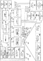
図1は、本発明を実施できる、適したコンピューティングシステム環境100の例を示している。コンピューティングシステム環境100は、適したコンピューティング環境の一例にすぎず、本発明の使用または機能の範囲に関する限定を示唆するものではない。また、コンピューティング環境100を、コンピューティング環境100の例に示した構成要素のいずれか1つ、またはその組合せに関連する依存性または必要条件を有しているものと解釈すべきではない。
FIG. 1 illustrates an example of a suitable
本発明は、他の多くの汎用または専用コンピューティングシステム環境または構成で動作可能である。本発明との使用に適したよく知られているコンピューティングシステム、環境、および/または構成の例には、それだけには限定されないが、パーソナルコンピュータ、サーバーコンピュータ、ハンドヘルドまたはラップトップ装置、マルチプロセッサシステム、マイクロプロセッサベースのシステム、セットトップボックス、プログラム可能家庭用電化製品、ネットワークPC、ミニコンピュータ、メインフレームコンピュータ、上記の任意のシステムまたは装置を含む分散コンピューティング環境などがある。 The invention is operational with many other general purpose or special purpose computing system environments or configurations. Examples of well-known computing systems, environments, and / or configurations suitable for use with the present invention include, but are not limited to, personal computers, server computers, handheld or laptop devices, multiprocessor systems, Microprocessor-based systems, set-top boxes, programmable consumer electronics, network PCs, minicomputers, mainframe computers, distributed computing environments including any of the systems or devices described above, and the like.
本発明は、コンピュータによって実行されるプログラムモジュールなどのコンピュータ実行可能命令の一般的なコンテキストで説明することができる。一般にプログラムモジュールは、特定のタスクを実行する、または特定の抽象データ型を実装するルーチン、プログラム、オブジェクト、構成要素、データ構造などを含む。また、本発明は、タスクが通信ネットワークによってリンクされているリモート処理装置によって実行される分散コンピューティング環境で実施するように設計されている。分散コンピューティング環境では、プログラムモジュールを、メモリ記憶装置を含むローカルおよびリモートのコンピュータ記憶媒体に置くことができる。 The invention may be described in the general context of computer-executable instructions, such as program modules, being executed by a computer. Generally, program modules include routines, programs, objects, components, data structures, etc. that perform particular tasks or implement particular abstract data types. The present invention is also designed to be implemented in a distributed computing environment where tasks are performed by remote processing devices that are linked by a communications network. In a distributed computing environment, program modules may be located in local and remote computer storage media including memory storage devices.
図1を参照すると、本発明を実施するシステムの例は、汎用コンピューティング装置をコンピュータ110の形で含んでいる。コンピュータ110の構成要素は、それだけには限定されないが、処理ユニット120、システムメモリ130、およびシステムメモリを含む様々なシステム構成要素を処理ユニット120に結合するシステムバス121を含む。システムバス121は、様々なバスアーキテクチャのうちの任意のものを使用するメモリバスまたはメモリコントローラ、周辺バス、およびローカルバスを含むいくつかのタイプのバス構造のうちどんなものでもよい。こうしたアーキテクチャには、それだけには限定されないが一例として、ISA(industry standard architecture)バス、MCA(micro channel architecture)バス、EISA(enhanced ISA)バス、VESA(video electronics standards association)ローカルバス、およびメザニンバスとしても知られているPCI(peripheral component interconnect)バスなどがある。
Referring to FIG. 1, an example of a system embodying the present invention includes a general-purpose computing device in the form of a
コンピュータ110は、一般に様々なコンピュータ可読媒体を含む。コンピュータ可読媒体は、コンピュータ110からアクセスできる使用可能な任意の媒体とすることができ、揮発性および不揮発性媒体、リムーバブルおよび非リムーバブル媒体を含む。コンピュータ可読媒体は、それだけには限定されないが一例として、コンピュータ記憶媒体および通信媒体を含み得る。コンピュータ記憶媒体には、コンピュータ可読命令、データ構造、プログラムモジュール、他のデータなど、情報を記憶するための任意の方法または技術で実施される揮発性および不揮発性のリムーバブルおよび非リムーバブル媒体がある。コンピュータ記憶媒体には、それだけには限定されないが、RAM、ROM、EEPROM、フラッシュメモリまたは他のメモリ技術、CD−ROM、デジタル多用途ディスク(DVD)または他の光ディスク記憶装置、磁気カセット、磁気テープ、磁気ディスク記憶装置または他の磁気記憶装置、または所望の情報の格納に使用でき、コンピュータ110からアクセスできる他の任意の媒体などがある。通信媒体は一般に、コンピュータ可読命令、データ構造、プログラムモジュール、または他のデータを搬送波または他の移送機構などの変調されたデータ信号に組み込む。これには任意の情報配送媒体がある。「変調されたデータ信号」という用語は、信号内の情報を符号化するように設定または変更された1つまたは複数のその特徴を有する信号を意味する。通信媒体には、それだけには限定されないが一例として、有線ネットワーク、直接配線された接続などの有線媒体、および音響、RF、赤外線、その他の無線媒体などの無線媒体がある。また、上記のどんな組合せでもコンピュータ可読媒体の範囲内に含まれるものとする。
システムメモリ130は、読取り専用メモリ(ROM)131やランダムアクセスメモリ(RAM)132など、揮発性および/または不揮発性メモリの形態のコンピュータ記憶媒体を含む。BIOS(basic input/output)133は、例えば起動中など、コンピュータ110内の要素間での情報の転送を助ける基本ルーチンを含み、一般にROM131に格納されている。RAM132は一般に、処理ユニット120から直接アクセス可能な、かつ/または処理ユニット120が現在処理しているデータおよび/またはプログラムモジュールを含む。図1は、それだけには限定されないが一例として、オペレーティングシステム134、アプリケーションプログラム135、他のプログラムモジュール136、およびプログラムデータ137を示している。
コンピュータ110は、他のリムーバブル/非リムーバブル、揮発性/不揮発性コンピュータ記憶媒体を含むこともできる。一例にすぎないが、図1は、非リムーバブル不揮発性磁気媒体から読み取り、あるいはそこに書き込むハードディスクドライブ141、リムーバブル不揮発性磁気ディスク152から読み取り、あるいはそこに書き込む磁気ディスクドライブ151、およびCD−ROMや他の光媒体など、リムーバブル不揮発性光ディスク156から読み取り、あるいはそこに書き込む光ディスクドライブ155を示している。動作環境の例で使用できる他のリムーバブル/非リムーバブル、揮発性/不揮発性コンピュータ記憶媒体には、それだけには限定されないが、磁気テープカセット、フラッシュメモリカード、デジタル多用途ディスク、デジタルビデオテープ、半導体RAM、半導体ROMなどがある。ハードディスクドライブ141は一般に、インターフェイス140などの非リムーバブル不揮発性メモリインターフェイスを介してシステムバス121に接続され、磁気ディスクドライブ151および光ディスクドライブ155は一般に、インターフェイス150などのリムーバブル不揮発性メモリインターフェイスによってシステムバス121に接続される。
上述し、図1に示したドライブおよびその関連のコンピュータ記憶媒体は、コンピュータ可読命令、データ構造、プログラムモジュール、およびコンピュータ110の他のデータの記憶を提供する。図1では例えば、ハードディスクドライブ141は、オペレーティングシステム144、アプリケーションプログラム145、他のプログラムモジュール146、およびプログラムデータ147を記憶するものとして示されている。これらの構成要素は、オペレーティングシステム134、アプリケーションプログラム135、他のプログラムモジュール136、およびプログラムデータ137と同じであっても、異なっていてもよいことに注意されたい。オペレーティングシステム144、アプリケーションプログラム145、他のプログラムモジュール146、およびプログラムデータ147は少なくとも異なるコピーであることを示すために、ここではそれらに異なる番号を付している。
The drives and associated computer storage media described above and shown in FIG. 1 provide storage of computer readable instructions, data structures, program modules, and other data for
ユーザは、キーボード162、マイクロフォン163、および一般にマウス、トラックボール、タッチパッドなどのポインティング装置161などの入力装置を介してコマンドおよび情報をコンピュータ110に入力することができる。他の入力装置(図示せず)には、ジョイスティック、ゲームパッド、衛星パラボラアンテナ、スキャナなどがある。これらおよび他の入力装置は、しばしばシステムバスに結合されているユーザ入力インターフェイス160を介して処理ユニット120に接続されるが、パラレルポート、ゲームポート、ユニバーサルシリアルバス(USB)など他のインターフェイスおよびバス構造で接続してもよい。モニタ191または他のタイプの表示装置もまた、ビデオインターフェイス190などのインターフェイスを介してシステムバス121に接続される。モニタに加えて、コンピュータは、出力周辺インターフェイス195などを介して接続できるスピーカー197、プリンタ196などの他の周辺出力装置を含むこともできる。
A user can enter commands and information into the
コンピュータ110は、リモートコンピュータ180など1つまたは複数のリモートコンピュータへの論理接続を使用してネットワーク式環境で操作される。リモートコンピュータ180は、パーソナルコンピュータ、ハンドヘルド装置、サーバー、ルーター、ネットワークPC、ピア装置、または他の一般のネットワークノードでよく、一般にコンピュータ110に関連して上述した多くまたはすべての要素を含む。図1に示した論理接続は、ローカルエリアネットワーク(LAN)171およびワイドエリアネットワーク(WAN)173を含むが、他のネットワークを含んでいてもよい。こうしたネットワーキング環境は、オフィス、全社規模のコンピュータネットワーク、イントラネット、およびインターネットではごく一般的である。
LANネットワーキング環境で使用する場合、コンピュータ110は、ネットワークインターフェイスまたはアダプタ170を介してLAN171に接続される。WANネットワーキング環境で使用する場合、コンピュータ110は一般に、モデム172、またはインターネットなどWAN173を介して通信を確立する他の手段を含む。モデム172は、内蔵のものでも外付けのものでもよく、ユーザ入力インターフェイス160または他の適切な機構を介してシステムバス121に接続することができる。ネットワーク式環境では、コンピュータ110に関連して示したプログラムモジュール、またはその一部をリモートメモリ記憶装置に格納することができる。図1は、それだけには限定されないが一例として、リモートアプリケーションプログラム185をメモリコンピュータ180上に存在するものとして示している。図示したネットワーク接続は例であり、コンピュータ間の通信リンクを確立する他の手段を使用してもよいことは理解されよう。
When used in a LAN networking environment,
図2は、オブジェクトリレーショナル(またはエンティティリレーショナル)データ記憶システムを示す図である。本発明では、エンティティは、「オブジェクト」という用語と同義の用語として使用される。E−Rシステム200は、リレーショナルデータベース204に格納されているデータに対応する1組のエンティティ(またはオブジェクト)202を含む。エンティティは、エンティティリレーショナル(ER)マップ208を使用するデータアクセスシステム206を介してリレーショナルデータにアクセスする。ERマップ208は、エンティティ202とリレーショナルデータベース204内のテーブルエンティティとの間のマッピングを含む。本発明は、E−Rシステム以外の他のシステムにおいても使用可能であり、図2に示すシステムは、本発明を使用できるシステムの一例にすぎないことに注意されたい。
FIG. 2 is a diagram illustrating an object-relational (or entity-relational) data storage system. In the present invention, an entity is used as a term synonymous with the term "object". The
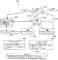
図3は、本発明の一実施形態によるビジネスコラボレーションフレームワーク(business collaboration framework)220の統一モデリング言語(UML)クラスの図である。フレームワーク220は、1つまたは複数のビジネスオブジェクト222を含む。ビジネスオブジェクト222は、オブジェクト222の様々なデータ要素を定義する静的モデルを含む。例えば、販売注文用のビジネスオブジェクトは、顧客名、出荷先住所、商品説明、価格など、様々なデータ要素を含むことができる。一実施形態では、ビジネスオブジェクト222は、ビジネスオブジェクト222から導出される他のオブジェクトの代わりにロジックを実装する基本クラスである。ビジネスオブジェクト222は、1つまたは複数のコラボレーション224、1つまたは複数のロール226、および1つまたは複数のプロパティ228に関連付けられる。
FIG. 3 is a diagram of a Unified Modeling Language (UML) class of a
フレームワーク220を使用すると、ビジネスロジックパターン(本明細書ではコラボレーションおよびロール)の実装は、パラメータ化され、異なるビジネスオブジェクトにわたって再利用可能である。パラメータ化とは、コラボレーションおよびコラボレーションロールの挙動を制御するパラメータをメタデータ内でセットアップする機能を指す。例えば、番号順ロールの場合、メタデータを使用して、シーケンスから取り出される任意の数が連続すべきであることを定義することができる。各コラボレーションロールは、どのメタデータをコラボレーション/コラボレーションロールに設定できるかを定義するスキーマを有することができる。後述するように、このメタデータは、プロパティとコラボレーションロールとjの間のバインド情報を指定するメタデータの他に追加してもよい。
Using the
コラボレーション224は、ビジネスアプリケーションの異なるビジネスオブジェクトによって再利用可能であり、これによって設計者は、ビジネスオブジェクト222内の様々なプロパティ(プロパティ228など)の挙動を設定することができる。コラボレーション224は、ビジネスロジックパターン、1組のロール(ロール226など)、ならびに各ロールの基数(その組の中の要素の数)、および各ロールが同じまたは異なるビジネスエンティティの他のロールとどのように対話するかを管理するルールを含む。コラボレーション224は、関連するインターフェイス230を含み、これによってビジネスアプリケーションにおいてコラボレーションが定義され、他のコラボレーションおよびロールとの対話が可能になる。
ロール226は、ビジネスオブジェクト222内の個々のプロパティ(例えばフィールドまたはオブジェクト)と関連する、あるいは複数のビジネスオブジェクトと関連するオブジェクトである。ロール226は、他のコラボレーションおよび/または他のロールと対話するために、ロール226にバインドされたプロパティの挙動を制御するためのビジネスロジックを含む。さらに、ロール226は、外部または内部フィールドを含む。外部フィールドは、他のロールまたは他のビジネスソフトウェアと通信するときに使用される。外部フィールドでは、ロールは、プロパティのインターセプトを制御し、ロールをビジネスオブジェクト222の静的モデル内のデータにバインドするロジックを含む。これについては後述する。内部フィールドは、特定のロール内でのみ使用され、特定のロールを介してのみアクセスされる。ロール226は、ロールを定義する、関連するインターフェイス232も含む。
ロール226は、関連するロールオンプロパティサブクラス234および/または関連するロールオンコラボレーションサブクラス236をさらに有することができる。ロールオンプロパティ234は、ビジネスオブジェクト222の静的モデルのプロパティ(またはフィールド)に関する、ビジネスアプリケーションで起こるイベントのプロパティをインターセプトするために使用される。ロールオンコラボレーションサブクラス236によって、ロール226は、他のコラボレーションと対話して、例えば他のコラボレーションからのイベントをインターセプトすることができる。
フレーム220は、関連するメタデータインターフェイス238も含む。メタデータインターフェイス238は、ロールによって定義されている挙動が与えられると、フレームワーク220によって、格納されているデータと対話するために使用される。特に、インターフェイス238によって、格納されているデータを、ロールによって定義されたように、ビジネスオブジェクト222の静的モデルで定義されたプロパティにバインドすることができる。コラボレーションが定義されると、ビジネスオブジェクトのプロパティがコラボレーションロールにバインドされる。この「バインド情報」は、適切なメタデータストアに格納される。
フレームワーク220内で起こる様々なイベントによって、少なくとも1つのコラボレーションおよびその関連するロールの実装が引き起こされる。こうしたイベントには、ビジネスエンティティの作成、更新、読取り、削除、ビジネスエンティティ内のプロパティの変更、ないしは改変などがある。例えば、販売注文を作成すると、簡単な番号ジェネレータコラボレーションがトリガ(またはインスタンス化)されてシーケンスに新しい販売注文番号を作成することができる。
Various events that occur within the
図4は、ビジネスコラボレーションを用いるアプリケーションを開発するときにアプリケーション開発者240によって実行されるタスクの例を示す概略図である。これらのタスクは、ビジネスオブジェクトのプロパティの静的モデルが定義された後で行うことができる。アプリケーション開発者240が実装するタスクは、コラボレーションの定義タスク242、ロールの定義タスク244を含む。ロールの定義タスク244は、コラボレーションへのロールの定義タスク248、フィールドへのロールの定義タスク250、ロールをフィールドとする定義タスク252、およびロールを可視インターフェイスとする定義246を使用することを含む。
FIG. 4 is a schematic diagram illustrating an example of tasks performed by the
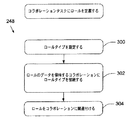
図5は、コラボレーションをビジネスエンティティにバインドするメタデータを設定するコラボレーションを定義するためのタスク242を完了するステップを示している。ステップ260で、ビジネスソリューションの実装に応じてコラボレーションタイプを決定する。例えば開発者240は、moneyコラボレーションを選択して、ある金額をある通貨から別の通貨に変換する、または通貨総額(aggregate currency)を選択してあるフィールドの複数のインスタンスを計算する(すなわち販売注文の明細の集計にわたって価格を追加する)ことができる。ステップ262で、コラボレーションをそのコラボレーションを制御するエンティティ上に作成する。つまりコラボレーションは、エンティティのメタデータ内に作成される。例えば、コラボレーションは、特定のビジネスオブジェクトに関連付けられ、それに関連して作成される。ステップ264で、コラボレーションを適切に識別するために、コラボレーションに名前を付ける。コラボレーションに名前が付けられると、次いでステップ266で、アプリケーション開発者は、そのコラボレーションに対するロールを定義することができる。このステップは、タスク244を実施することによって行なわれる。後でロールを使用して、他のエンティティ内のオブジェクトをロールにバインドすることができる。各ロールが定義された後、ステップ268で、ビジネスエンティティにおけるモデルが有効になる。コラボレーションを使用してモデルがいったん有効になると、ステップ270でこのコラボレーションを保存する。
FIG. 5 illustrates steps to complete a
タスク248、250、および252を使用してロールを定義することができる。図6は、ロールをフィールドとして定義するタスク252を完了するステップを示す。タスク252を使用して、ビジネスオブジェクト内のフィールドとして働くようにロールを定義する。タスクはステップ280で開始し、ここでロールタイプを設定する。ロールタイプは、日付、整数、小数、オブジェクトなど、またはユーザ定義タイプを組み込むことができる。ステップ282で、ロールタイプをフィールドとしてビジネスエンティティに追加する。したがってロールは、ビジネスエンティティのプロパティオブジェクトとして定義される。ステップ284で、ロールを適切に識別するために、ロールに名前を付ける。次に、ステップ286で、ロールを適切なコラボレーションに関連付ける。
Roles can be defined using
図7は、フィールドにロールを定義するタスク250を完了するステップを示す。タスク250を使用して、ビジネスオブジェクトに存在するフィールドの挙動を定義する。ステップ290で、ロールタイプを設定する。ステップ292で、ロールタイプをそのロールのデータを保持するフィールドに接続する。次に、ステップ294で、ロールをコラボレーションに関連付ける。
FIG. 7 shows steps for completing a
図8は、コラボレーションにロールを定義するタスク248を完了するステップを示す。タスク248を使用して、別のコラボレーションに関連するロールを実装する。ステップ300で、ロールタイプを設定する。ステップ302で、ロールタイプをロールのソースを保持するコラボレーションに接続する。ステップ304で、ロールをコラボレーションに関連付ける。
FIG. 8 shows the steps for completing
図9は、ビジネスアプリケーション内のコードからアクセスできるようにロールを可視インターフェイスとして定義するタスク246を示す。タスク246は、タスク248および250のサブタスクである。ステップ310で、可視にすべきロールを選択する。ステップ312で、ロールを表示するために、プロパティ可視フラグをtrueに設定する。
FIG. 9 illustrates a
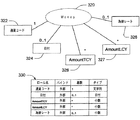
図10は、コラボレーションの例および関連するロールの表を示す。Moneyコラボレーション320は、通貨間で金額を変換するために使用される。このコラボレーションは、例えば取引通貨が会計帳簿に入力された現地通貨とは異なる販売注文の金額を更新するときに役立つ。会計通貨とは異なる取引通貨が入力されると、取引通貨額が自動的に変換され、会計帳簿が会計通貨値で更新される。Moneyコラボレーション320は、通貨コードロール322、日付ロール324、取引通貨額ロール(AmountTCYロール)326、現地(または会計)通貨額ロール(AmountLCYロール)327、および為替レートロール328を含む。Moneyコラボレーションの実装では、デフォルトの通貨(すなわち会計通貨)を仮定する。為替レートロール328は、アプリケーション開発者から可視である必要はなく、また、個別のロールを必要とせずに、Moneyコラボレーション320自体のビジネスロジックに含めることもできることは注目に値する。
FIG. 10 shows a table of example collaborations and associated roles.
表330は、Moneyコラボレーション320におけるロールの定義を含む。表330の行は、ロールに関する情報を表し、列はロールの特定の特徴に関する情報、すなわちロール名、バインド、基数、およびタイプを表す。通貨コードロール322は、外部フィールド(したがってそのバインドは外部)であり、文字列である。通貨コードロール322の基数は1である。これは、Moneyコラボレーション320では常に唯一のコードロールが存在することを意味する。日付ロール324は、外部フィールドで、日付であり、その基数は0または1のいずれかである(0..1で示す)。AmountTCYロール326およびAmountLCYロール327は外部フィールドで、小数であり、任意の数の個々のロールを含むことができる(*で示す)。為替レートロール328は、外部フィールドで、小数であり、その基数は0または1である。
Table 330 includes the definition of roles in
図11は、通貨間で金額を変換する実装例を示す。この例では、現地通貨がわかっていると仮定する。SomeBusinessClass350で示したビジネスエンティティがビジネスアプリケーションで定義されている。例えば、SomeBusinessClass350は、取引通貨と現地通貨との間の変換を含む販売注文とすることができる。SomeBusinessClass350は、CurrencyCode取引通貨コード352、AmountLCY(現地(または会計)通貨額)354、およびAmountTCY(取引通貨額)356の3つのフィールドを含む。必要に応じて、クラス350は、ExchangeRateフィールド358を含むこともできる。
FIG. 11 shows an implementation example of converting the amount between currencies. For this example, assume that the local currency is known. The business entity indicated by SomeBusinessClass350 is defined in the business application. For example,
Moneyコラボレーション360は、CCDRole362、LCYRole364、TCYRole366、およびEXRRole368のロールを含む。コラボレーション360を実装すると、CCDRole362がCurrencyCodeフィールド352にバインドされ、LCYRole364がAmountLCYフィールド354にバインドされ、TCYRole366がAmountTCYフィールド356にバインドされる。ExchangeRateフィールド358を使用している場合、EXRRole368がそれにバインドされる。
メタデータ構造370は、ロールをそれぞれのフィールドにバインドするバインド情報を含む。例えば、メタデータ構造370内の情報MoneyCollaboration.CCDRoleおよびSomeBusinessClass.CurrencyCodeによってこのバインドが提供される。SomeBusinessClassをインスタンス化する(例えば新しい販売注文が要求される)と、メタデータは、これらのフィールドにバインドされ、Moneyコラボレーション360がインスタンス化される。
図12は、本発明の一実施形態によるMoneyコラボレーション360を使用した取引通貨額の更新の方法400を示す。ステップ402で、ユーザがCurrencyCodeフィールド352を更新する。ステップ404で、更新をインターセプトされ、CCDRole362に適用する。通貨コードのフィールドが更新されるといつでもインターセプトが行われる。次いで、ステップ406で、更新された通貨コードは、EXRRole368に委任され、そこで為替レートを計算し、ExchangeRateフィールド358を更新する。
FIG. 12 illustrates a
次にステップ408で、ユーザがAmountLCYフィールド354に金額を入力する。再度、この更新によってインターセプトが引き起こされる。ステップ410で、新しい金額を更新し、Moneyコラボレーション360に委任し、ここで為替レートおよび現地通貨額に基づいて対象の通貨値を新たに計算する。次いでステップ412でAmountTCYフィールド356を更新する。
Next, at
コラボレーションは、いくつかのエンティティにわたって定義してもよく、また他のコラボレーションと対話することもできることに注意されたい。図13は、コラボレーションが複数のエンティティにわたって使用される環境の例を示す。請求書エンティティ420、支払いエンティティ422、および顧客エンティティ424を示している。Applyコラボレーションは、支払い、請求書、および残高のロールを含む。請求書ロールは、請求書エンティティを使用して正確な請求書を顧客に送信できるようにするために、支払いに関する情報を含んでいる。同様に、顧客エンティティは、残高ロールを使用して顧客の請求書値および支払い値を計算して適切な残高を決定する。
Note that a collaboration may be defined across several entities and may also interact with other collaborations. FIG. 13 shows an example of an environment in which collaboration is used across multiple entities. A
図14は、いくつかのコラボレーションが相互に作用する環境を示す。Moneyコラボレーション440、Money amountコラボレーション442、Applyコラボレーション444、およびAggregationコラボレーション446を示している。Money amountコラボレーション442は、ビジネスアプリケーションの値を計算するために、Moneyコラボレーション440、Applyコラボレーション444、およびAggregationコラボレーション446からの値を使用する。また、Moneyコラボレーション440の金額ロールがMoney amountコラボレーション442の挙動を定義するMoney amountコラボレーション442も示されている。
FIG. 14 illustrates an environment where several collaborations interact. A
ビジネスエンティティと関連付けられたコラボレーションおよびロールを実装することによって、一般のビジネスロジックを様々な状況において再利用することができる。ロールは、ビジネスオブジェクトのプロパティが更新されると、プロパティのビジネスロジックを実行するように、メタデータのインスタンスにバインドされる。したがって、ビジネスアプリケーションを通じてビジネスロジックのこうしたインスタンスを再生する必要がなく、時間および開発コストが節約される。 By implementing the collaborations and roles associated with business entities, common business logic can be reused in various situations. A role is bound to an instance of metadata so that when the properties of a business object are updated, the business logic of the property is executed. Thus, there is no need to regenerate such instances of business logic through business applications, saving time and development costs.
本発明は、特定の実施形態に関連して説明してきたが、本発明の意図および範囲から逸脱することなく形態および詳細に変更を加えることができることを当業者であれば理解されよう。 Although the present invention has been described with reference to particular embodiments, workers skilled in the art will recognize that changes may be made in form and detail without departing from the spirit and scope of the invention.
100 コンピューティングシステム環境
110 コンピュータ
120 処理ユニット
121 システムバス
130 システムメモリ
131 読取り専用メモリ(ROM)
132 ランダムアクセスメモリ(RAM)
133 基本入出力システム(BIOS)
134 オペレーティングシステム
135 アプリケーションプログラム
136 他のプログラムモジュール
137 プログラムデータ
140 インターフェイス
141 ハードディスクドライブ
144 オペレーティングシステム
145 アプリケーションプログラム
146 他のプログラムモジュール
147 プログラムデータ
150 インターフェイス
151 磁気ディスクドライブ
152 リムーバブル不揮発性磁気ディスク
155 光ディスクドライブ
156 リムーバブル不揮発性光ディスク
160 ユーザ入力インターフェイス
161 ポインティング装置
162 キーボード
163 マイクロフォン
170 ネットワークインターフェイスまたはアダプタ
171 ローカルエリアネットワーク(LAN)
172 モデム
173 ワイドエリアネットワーク(WAN)
180 リモートコンピュータ
185 リモートアプリケーションプログラム
190 ビデオインターフェイス
191 モニタ
195 出力周辺インターフェイス
196 プリンタ
197 スピーカー
200 E−Rシステム
202 オブジェクト
204 リレーショナルデータベース
206 データアクセスシステム
208 エンティティリレーショナル(ER)マップ
220 ビジネスコラボレーションフレームワーク
222 ビジネスオブジェクト
224 コラボレーション
226 ロール
228 プロパティ
230 インターフェイス
232 インターフェイス
234 ロールオンプロパティサブクラス
236 ロールオンコラボレーションサブクラス
238 関連するメタデータインターフェイス
240 アプリケーション開発者
242 コラボレーションの定義タスク
244 ロールの定義タスク
246 ロールを可視インターフェイスとして定義
248 コラボレーションへのロールの定義タスク
250 フィールドへのロールの定義タスク
252 ロールをフィールドとする定義タスク
320 Moneyコラボレーション
322 通貨コードロール
324 日付ロール
326 取引通貨額ロール
327 現地(または会計)通貨額ロール
328 為替レートロール
330 表
350 SomeBusinessClass
352 CurrencyCode取引通貨コードフィールド
354 AmountLCYフィールド
356 AmountTCYフィールド
358 ExchangeRateフィールド
360 Moneyコラボレーション
362 CCDRole
364 LCYRole
366 TCYRole
368 EXRRole
370 メタデータ構造
400 方法
420 請求書エンティティ
422 支払いエンティティ
424 顧客エンティティ
440 Moneyコラボレーション
442 Money amountコラボレーション
444 Applyコラボレーション
446 Aggregationコラボレーション
REFERENCE SIGNS
132 Random Access Memory (RAM)
133 Basic Input / Output System (BIOS)
134 Operating system 135
180
352 CurrencyCode transaction
364 LCYRole
366 TCYRole
368 EXRRole
370
Claims (22)
ビジネスエンティティに関連付けられたイベントを自動的にインターセプトすること、
前記イベントおよびビジネスロジックに基づいて結果を計算するために前記イベントがインターセプトされると前記ビジネスロジックの実装をインスタンス化すること、および
前記結果を前記フレームワーク内のプロパティにバインドすること
を含むことを特徴とする方法。 A method of implementing business logic in a framework,
Automatically intercept events associated with business entities,
Instantiating an implementation of the business logic when the event is intercepted to calculate a result based on the event and business logic, and binding the result to a property in the framework. Features method.
格納されている情報に関連付けられたプロパティを含むビジネスエンティティモジュールと、
前記ビジネスエンティティモジュールに関連付けられ、前記プロパティに関連付けられたロールを含み、前記関連するビジネスエンティティのイベントにビジネスロジックを実装して前記ビジネスロジックのイベントに基づいて結果を計算するように構成されているコラボレーションモジュールと
を含むことを特徴とするシステム。 A system for managing and storing information,
A business entity module that contains properties associated with the stored information,
A role associated with the business entity module, including a role associated with the property, configured to implement business logic in an event of the related business entity and calculate a result based on the event of the business logic. A system comprising: a collaboration module;
The system of claim 20, wherein the second property is included in a second business entity module.
Applications Claiming Priority (1)
| Application Number | Priority Date | Filing Date | Title |
|---|---|---|---|
| US10/389,685 US20040181418A1 (en) | 2003-03-12 | 2003-03-12 | Parameterized and reusable implementations of business logic patterns |
Related Child Applications (1)
| Application Number | Title | Priority Date | Filing Date |
|---|---|---|---|
| JP2011255582A Division JP2012038354A (en) | 2003-03-12 | 2011-11-22 | Method and system for implementing business logic pattern |
Publications (2)
| Publication Number | Publication Date |
|---|---|
| JP2004280822A true JP2004280822A (en) | 2004-10-07 |
| JP2004280822A5 JP2004280822A5 (en) | 2007-04-26 |
Family
ID=32824833
Family Applications (2)
| Application Number | Title | Priority Date | Filing Date |
|---|---|---|---|
| JP2004069828A Pending JP2004280822A (en) | 2003-03-12 | 2004-03-11 | Parameterized and reusable implementation of business logic pattern |
| JP2011255582A Pending JP2012038354A (en) | 2003-03-12 | 2011-11-22 | Method and system for implementing business logic pattern |
Family Applications After (1)
| Application Number | Title | Priority Date | Filing Date |
|---|---|---|---|
| JP2011255582A Pending JP2012038354A (en) | 2003-03-12 | 2011-11-22 | Method and system for implementing business logic pattern |
Country Status (3)
| Country | Link |
|---|---|
| US (1) | US20040181418A1 (en) |
| EP (1) | EP1460572A3 (en) |
| JP (2) | JP2004280822A (en) |
Cited By (3)
| Publication number | Priority date | Publication date | Assignee | Title |
|---|---|---|---|---|
| WO2007052959A1 (en) * | 2005-11-03 | 2007-05-10 | Ktfreetel Co., Ltd. | Open mobile business supporting system and method |
| KR100738039B1 (en) | 2005-11-14 | 2007-07-12 | 주식회사 케이티프리텔 | Business logic processing method and apparatus in open mobile business supporting system |
| US8073932B2 (en) | 2005-11-03 | 2011-12-06 | Kt Corporation | Business logic device and processing method |
Families Citing this family (10)
| Publication number | Priority date | Publication date | Assignee | Title |
|---|---|---|---|---|
| US7698293B2 (en) * | 2005-01-28 | 2010-04-13 | Microsoft Corporation | System and methods for capturing structure of data models using entity patterns |
| US7636911B2 (en) * | 2005-01-28 | 2009-12-22 | Microsoft Corporation | System and methods for capturing structure of data models using entity patterns |
| US20070088589A1 (en) * | 2005-10-17 | 2007-04-19 | International Business Machines Corporation | Method and system for assessing automation package readiness and and effort for completion |
| US20070192367A1 (en) * | 2006-02-16 | 2007-08-16 | Microsoft Corporation | Generic expression framework for computer implementable expressions |
| US7945596B2 (en) | 2006-06-20 | 2011-05-17 | Microsoft Corproation | Programming model for customized data objects |
| US8689174B2 (en) * | 2006-12-28 | 2014-04-01 | Sap Ag | Extensibility of pattern components |
| US20080183514A1 (en) * | 2007-01-29 | 2008-07-31 | International Business Machines Corporation | System and Methods for Using Solution Building Blocks |
| US7836137B2 (en) * | 2007-03-23 | 2010-11-16 | Microsoft Corporation | E-mail tool management shell command set |
| US9406044B2 (en) * | 2011-12-22 | 2016-08-02 | Sap Se | Rule-based determination and validation in business object processing |
| TWI570582B (en) * | 2015-11-12 | 2017-02-11 | 財團法人資訊工業策進會 | Asset storage system, method and non-volatile computer readable storage medium for storing thereof |
Family Cites Families (22)
| Publication number | Priority date | Publication date | Assignee | Title |
|---|---|---|---|---|
| US6067525A (en) * | 1995-10-30 | 2000-05-23 | Clear With Computers | Integrated computerized sales force automation system |
| US5958012A (en) * | 1996-07-18 | 1999-09-28 | Computer Associates International, Inc. | Network management system using virtual reality techniques to display and simulate navigation to network components |
| JPH11175329A (en) * | 1997-12-08 | 1999-07-02 | Hitachi Ltd | Application linking method and device therefor |
| US6507845B1 (en) * | 1998-09-14 | 2003-01-14 | International Business Machines Corporation | Method and software for supporting improved awareness of and collaboration among users involved in a task |
| US6694316B1 (en) * | 1999-03-23 | 2004-02-17 | Microstrategy Inc. | System and method for a subject-based channel distribution of automatic, real-time delivery of personalized informational and transactional data |
| US6789252B1 (en) * | 1999-04-15 | 2004-09-07 | Miles D. Burke | Building business objects and business software applications using dynamic object definitions of ingrediential objects |
| JP2000353085A (en) * | 1999-06-10 | 2000-12-19 | Pfu Ltd | Software parts cooperative device and recording medium |
| US6678882B1 (en) * | 1999-06-30 | 2004-01-13 | Qwest Communications International Inc. | Collaborative model for software systems with synchronization submodel with merge feature, automatic conflict resolution and isolation of potential changes for reuse |
| US6959268B1 (en) * | 1999-09-21 | 2005-10-25 | Lockheed Martin Corporation | Product catalog for use in a collaborative engineering environment and method for using same |
| US6950802B1 (en) * | 2000-07-25 | 2005-09-27 | International Business Machines Corporation | System and method for systems integration |
| US7353494B2 (en) * | 2000-10-26 | 2008-04-01 | Microsoft Corporation | System and method supporting configurable object definitions |
| ATE411558T1 (en) * | 2000-11-09 | 2008-10-15 | Navision As | AUTOMATICALLY GENERATED TASK SEQUENCE |
| US7634726B2 (en) * | 2001-01-05 | 2009-12-15 | International Business Machines Corporation | Technique for automated e-business services |
| US20020149617A1 (en) * | 2001-03-30 | 2002-10-17 | Becker David F. | Remote collaboration technology design and methodology |
| WO2002082221A2 (en) * | 2001-04-06 | 2002-10-17 | Vert Tech Llc | A method and systems for creating e-marketplace operations |
| JP2002351660A (en) * | 2001-05-29 | 2002-12-06 | Mitsubishi Electric Corp | System, method, program for linking software component and computer readable recording medium having program recorded thereon |
| JP2002366353A (en) * | 2001-06-05 | 2002-12-20 | Skill Informations Co Ltd | Middleware system for general framework development |
| US7421704B2 (en) * | 2001-07-05 | 2008-09-02 | Computer Associates Think, Inc. | System and method for identifying and generating business events |
| US20040103147A1 (en) * | 2001-11-13 | 2004-05-27 | Flesher Kevin E. | System for enabling collaboration and protecting sensitive data |
| JP4490026B2 (en) * | 2002-01-28 | 2010-06-23 | 日立オムロンターミナルソリューションズ株式会社 | Customizable information processing device |
| US7346893B2 (en) * | 2002-03-28 | 2008-03-18 | Sap Ag | Exchange infrastructure system and method |
| US20030187706A1 (en) * | 2002-03-29 | 2003-10-02 | Buchmiller Jeffry L. | Innovation engine portal method and system |
-
2003
- 2003-03-12 US US10/389,685 patent/US20040181418A1/en not_active Abandoned
-
2004
- 2004-03-11 JP JP2004069828A patent/JP2004280822A/en active Pending
- 2004-03-11 EP EP04005844A patent/EP1460572A3/en not_active Withdrawn
-
2011
- 2011-11-22 JP JP2011255582A patent/JP2012038354A/en active Pending
Cited By (7)
| Publication number | Priority date | Publication date | Assignee | Title |
|---|---|---|---|---|
| WO2007052959A1 (en) * | 2005-11-03 | 2007-05-10 | Ktfreetel Co., Ltd. | Open mobile business supporting system and method |
| US8073932B2 (en) | 2005-11-03 | 2011-12-06 | Kt Corporation | Business logic device and processing method |
| US8229998B2 (en) | 2005-11-03 | 2012-07-24 | Kt Corporation | Open interface device and method |
| US8230040B2 (en) | 2005-11-03 | 2012-07-24 | Kt Corporation | Open mobile business supporting system and method |
| US8463841B2 (en) | 2005-11-03 | 2013-06-11 | Kt Corporation | Legacy cooperation device and processing method |
| US8756126B2 (en) | 2005-11-03 | 2014-06-17 | Kt Corporation | Billing device and processing method |
| KR100738039B1 (en) | 2005-11-14 | 2007-07-12 | 주식회사 케이티프리텔 | Business logic processing method and apparatus in open mobile business supporting system |
Also Published As
| Publication number | Publication date |
|---|---|
| JP2012038354A (en) | 2012-02-23 |
| EP1460572A3 (en) | 2004-12-08 |
| EP1460572A2 (en) | 2004-09-22 |
| US20040181418A1 (en) | 2004-09-16 |
Similar Documents
| Publication | Publication Date | Title |
|---|---|---|
| JP2012038354A (en) | Method and system for implementing business logic pattern | |
| US7424485B2 (en) | Method and apparatus for generating user interfaces based upon automation with full flexibility | |
| US8312416B2 (en) | Software model business process variant types | |
| US8327319B2 (en) | Software model process interaction | |
| US8407664B2 (en) | Software model business objects | |
| US7363578B2 (en) | Method and apparatus for mapping a data model to a user interface model | |
| US8370794B2 (en) | Software model process component | |
| US8448137B2 (en) | Software model integration scenarios | |
| US20050203760A1 (en) | Project time and expense | |
| US20070186209A1 (en) | Software modeling | |
| US20080109467A1 (en) | Data entity centric approach for designing workflows | |
| EP2049988A2 (en) | Defining a status model for a computer system | |
| JPH1173321A (en) | Method for developing framework and software system | |
| EP2041647A1 (en) | Using status models with state guards in a computer system | |
| US20060026506A1 (en) | Test display module for testing application logic independent of specific user interface platforms | |
| US8239299B2 (en) | Type-driven rules for financial intellegence | |
| US20170236119A1 (en) | System and method for implementing multi-rate currency aspects of multi-book accounting | |
| Duffy et al. | C# for Financial Markets | |
| US20060026522A1 (en) | Method and apparatus for revising data models and maps by example | |
| US11126967B2 (en) | Dynamic markup language-driven product administration system | |
| US20050060309A1 (en) | Query objects | |
| Tawhid et al. | Integrating Performance Analysis in Software Product Line Development Process | |
| Mauser | A reference model for savings bank | |
| Box | OO technology for the insurance industry |
Legal Events
| Date | Code | Title | Description |
|---|---|---|---|
| A521 | Request for written amendment filed |
Free format text: JAPANESE INTERMEDIATE CODE: A523 Effective date: 20070308 |
|
| A621 | Written request for application examination |
Free format text: JAPANESE INTERMEDIATE CODE: A621 Effective date: 20070308 |
|
| A131 | Notification of reasons for refusal |
Free format text: JAPANESE INTERMEDIATE CODE: A131 Effective date: 20100518 |
|
| A521 | Request for written amendment filed |
Free format text: JAPANESE INTERMEDIATE CODE: A523 Effective date: 20100818 |
|
| A131 | Notification of reasons for refusal |
Free format text: JAPANESE INTERMEDIATE CODE: A131 Effective date: 20100910 |
|
| A521 | Request for written amendment filed |
Free format text: JAPANESE INTERMEDIATE CODE: A523 Effective date: 20101210 |
|
| A131 | Notification of reasons for refusal |
Free format text: JAPANESE INTERMEDIATE CODE: A131 Effective date: 20110204 |
|
| A601 | Written request for extension of time |
Free format text: JAPANESE INTERMEDIATE CODE: A601 Effective date: 20110506 |
|
| A602 | Written permission of extension of time |
Free format text: JAPANESE INTERMEDIATE CODE: A602 Effective date: 20110511 |
|
| A521 | Request for written amendment filed |
Free format text: JAPANESE INTERMEDIATE CODE: A523 Effective date: 20110701 |
|
| A02 | Decision of refusal |
Free format text: JAPANESE INTERMEDIATE CODE: A02 Effective date: 20110722 |
|
| A521 | Request for written amendment filed |
Free format text: JAPANESE INTERMEDIATE CODE: A523 Effective date: 20111122 |
|
| RD13 | Notification of appointment of power of sub attorney |
Free format text: JAPANESE INTERMEDIATE CODE: A7433 Effective date: 20111124 |
|
| A521 | Request for written amendment filed |
Free format text: JAPANESE INTERMEDIATE CODE: A821 Effective date: 20111124 |
|
| A911 | Transfer to examiner for re-examination before appeal (zenchi) |
Free format text: JAPANESE INTERMEDIATE CODE: A911 Effective date: 20120124 |
|
| A912 | Re-examination (zenchi) completed and case transferred to appeal board |
Free format text: JAPANESE INTERMEDIATE CODE: A912 Effective date: 20120217 |
|
| A601 | Written request for extension of time |
Free format text: JAPANESE INTERMEDIATE CODE: A601 Effective date: 20120613 |
|
| A602 | Written permission of extension of time |
Free format text: JAPANESE INTERMEDIATE CODE: A602 Effective date: 20120618 |
|
| A601 | Written request for extension of time |
Free format text: JAPANESE INTERMEDIATE CODE: A601 Effective date: 20120713 |
|
| A602 | Written permission of extension of time |
Free format text: JAPANESE INTERMEDIATE CODE: A602 Effective date: 20120719 |