JP2004272909A - Verification of system at designing - Google Patents
Verification of system at designing Download PDFInfo
- Publication number
- JP2004272909A JP2004272909A JP2004063227A JP2004063227A JP2004272909A JP 2004272909 A JP2004272909 A JP 2004272909A JP 2004063227 A JP2004063227 A JP 2004063227A JP 2004063227 A JP2004063227 A JP 2004063227A JP 2004272909 A JP2004272909 A JP 2004272909A
- Authority
- JP
- Japan
- Prior art keywords
- instance
- definition
- constraint
- relationship
- constraints
- Prior art date
- Legal status (The legal status is an assumption and is not a legal conclusion. Google has not performed a legal analysis and makes no representation as to the accuracy of the status listed.)
- Pending
Links
- 238000012795 verification Methods 0.000 title claims abstract description 52
- 238000013461 design Methods 0.000 claims abstract description 50
- 238000000034 method Methods 0.000 claims description 111
- 230000008569 process Effects 0.000 claims description 96
- 238000004891 communication Methods 0.000 claims description 55
- 230000003993 interaction Effects 0.000 claims description 22
- 230000000977 initiatory effect Effects 0.000 claims 3
- 238000012938 design process Methods 0.000 abstract description 11
- 238000011156 evaluation Methods 0.000 description 47
- 238000011161 development Methods 0.000 description 36
- 230000009471 action Effects 0.000 description 24
- 238000006243 chemical reaction Methods 0.000 description 23
- 230000006870 function Effects 0.000 description 23
- 238000012546 transfer Methods 0.000 description 19
- 230000008859 change Effects 0.000 description 17
- 238000003860 storage Methods 0.000 description 17
- 238000010200 validation analysis Methods 0.000 description 16
- 238000012545 processing Methods 0.000 description 14
- 230000008676 import Effects 0.000 description 13
- 238000005266 casting Methods 0.000 description 9
- 230000003287 optical effect Effects 0.000 description 9
- 230000006399 behavior Effects 0.000 description 8
- 238000004088 simulation Methods 0.000 description 8
- 238000012508 change request Methods 0.000 description 7
- 230000009466 transformation Effects 0.000 description 7
- 238000004364 calculation method Methods 0.000 description 6
- 238000013507 mapping Methods 0.000 description 6
- 230000007246 mechanism Effects 0.000 description 6
- 238000010586 diagram Methods 0.000 description 5
- 238000001914 filtration Methods 0.000 description 5
- 238000009434 installation Methods 0.000 description 5
- 238000004422 calculation algorithm Methods 0.000 description 4
- 230000001419 dependent effect Effects 0.000 description 4
- 230000000694 effects Effects 0.000 description 4
- 238000007726 management method Methods 0.000 description 4
- 238000010276 construction Methods 0.000 description 3
- 238000012854 evaluation process Methods 0.000 description 3
- 239000000203 mixture Substances 0.000 description 3
- 230000006855 networking Effects 0.000 description 3
- 230000002093 peripheral effect Effects 0.000 description 3
- 230000001960 triggered effect Effects 0.000 description 3
- 238000004458 analytical method Methods 0.000 description 2
- 230000027455 binding Effects 0.000 description 2
- 238000009739 binding Methods 0.000 description 2
- 230000015572 biosynthetic process Effects 0.000 description 2
- 125000004122 cyclic group Chemical group 0.000 description 2
- 238000009826 distribution Methods 0.000 description 2
- 238000004519 manufacturing process Methods 0.000 description 2
- 230000007935 neutral effect Effects 0.000 description 2
- 238000000926 separation method Methods 0.000 description 2
- 230000003068 static effect Effects 0.000 description 2
- 238000003786 synthesis reaction Methods 0.000 description 2
- 230000008685 targeting Effects 0.000 description 2
- 238000012360 testing method Methods 0.000 description 2
- 238000000844 transformation Methods 0.000 description 2
- 238000003491 array Methods 0.000 description 1
- 230000001413 cellular effect Effects 0.000 description 1
- 238000004883 computer application Methods 0.000 description 1
- 230000008878 coupling Effects 0.000 description 1
- 238000010168 coupling process Methods 0.000 description 1
- 238000005859 coupling reaction Methods 0.000 description 1
- 238000013500 data storage Methods 0.000 description 1
- 238000009795 derivation Methods 0.000 description 1
- 238000012942 design verification Methods 0.000 description 1
- 238000001514 detection method Methods 0.000 description 1
- 238000005516 engineering process Methods 0.000 description 1
- 230000036541 health Effects 0.000 description 1
- 238000011900 installation process Methods 0.000 description 1
- 230000004807 localization Effects 0.000 description 1
- 238000005259 measurement Methods 0.000 description 1
- 230000005055 memory storage Effects 0.000 description 1
- 230000000737 periodic effect Effects 0.000 description 1
- 230000000644 propagated effect Effects 0.000 description 1
- 238000011160 research Methods 0.000 description 1
- 230000004044 response Effects 0.000 description 1
- 238000005096 rolling process Methods 0.000 description 1
- 239000000344 soap Substances 0.000 description 1
- 238000013519 translation Methods 0.000 description 1
- 230000007723 transport mechanism Effects 0.000 description 1
- 230000000007 visual effect Effects 0.000 description 1
Images


Classifications
-
- G—PHYSICS
- G06—COMPUTING; CALCULATING OR COUNTING
- G06F—ELECTRIC DIGITAL DATA PROCESSING
- G06F8/00—Arrangements for software engineering
- G06F8/10—Requirements analysis; Specification techniques
Landscapes
- Engineering & Computer Science (AREA)
- General Engineering & Computer Science (AREA)
- Theoretical Computer Science (AREA)
- Software Systems (AREA)
- Physics & Mathematics (AREA)
- General Physics & Mathematics (AREA)
- Stored Programmes (AREA)
- Debugging And Monitoring (AREA)
- Computer And Data Communications (AREA)
- Communication Control (AREA)
- Management, Administration, Business Operations System, And Electronic Commerce (AREA)
Abstract
Description
本発明は、システムの設計に関し、より詳細には、システムの設計時検証に関する。 The present invention relates to system design, and more particularly to system design verification.
過去数年間にインターネットの使用量は爆発的に増加し、今も成長を続けている。人々は、電子メール、オンラインショッピング、ニュースおよび情報の収集、音楽鑑賞、ビデオクリップ鑑賞、求職活動などのようなワールドワイドウェブ(または単に「ウェブ」)で提供される多くのサービスに非常に満足するようになってきた。インターネットベースのサービスへの需要が増大するのに合わせて、ウェブサイトをホスティングし、それらのサイトに対するバックエンドサービスを提供し、それらのサイトに関連するデータを記憶すること専用のコンピュータシステムが驚異的な成長を見せている。 Internet usage has exploded in the past few years and is still growing. People are very satisfied with the many services offered on the World Wide Web (or simply "Web"), such as email, online shopping, news and information gathering, listening to music, watching video clips, job hunting, etc. It has become. As the demand for Internet-based services increases, computer systems dedicated to hosting websites, providing back-end services to those sites, and storing data related to those sites are phenomenal. Is showing great growth.
分散型コンピュータシステムの1つの種類は、ネットワークベースのサービスをホスティングするための多くのコンピュータを収容する特別に設計された複合システムであるデータセンタ(例えば、インターネットデータセンタ(IDC)または企業データセンタ(EDC))である。「ウェブファーム」または「サーバファーム」という名称でも通用しているデータセンタは、通常、空調された物理的に安全な建物内に数百から数千ものコンピュータを収容する。データセンタは、通常、信頼性のあるインターネットアクセス、信頼性のある電力供給、および安全な動作環境を提供する。 One type of distributed computer system is a data center (eg, an Internet data center (IDC) or an enterprise data center (eg, an Internet data center (IDC) or an enterprise data center (IDC)), which is a specially designed complex system that houses many computers for hosting network-based services. EDC)). Data centers, also commonly referred to as "web farms" or "server farms," typically house hundreds to thousands of computers in air-conditioned, physically secure buildings. Data centers typically provide reliable Internet access, reliable power supply, and a secure operating environment.
様々なデータセンタは、そのデータセンタで実行されるアプリケーションに課される様々な要件を有することができる。例えば様々なデータセンタは、様々な種類のセキュリティが施行されることを要求し、またはアプリケーションが様々な通信プロトコルをサポートすることを要求する場合がある。さらに、いくつかのデータセンタは、経時的にそれらの要件を変更する場合がある。データセンタ間でのこれらの違いはアプリケーションの設計プロセスを困難にする。つまり、所望の1つ以上のデータセンタで彼らのアプリケーションが実行されることができるように、設計者はそれらの異なる要件に気付き、彼らのアプリケーションの設計にそれらの要件を反映させなければならない。 Different data centers may have different requirements placed on applications running on the data center. For example, different data centers may require different types of security to be enforced or require applications to support different communication protocols. In addition, some data centers may change their requirements over time. These differences between data centers make the application design process difficult. That is, designers must be aware of those different requirements and reflect those requirements in the design of their applications so that their applications can be run on the desired data center or data centers.
さらに、現状、設計者は、通常、アプリケーションをデータセンタに配置する際に、彼らのアプリケーションが特定のデータセンタで実行されるか否かを評価することしかできない。データセンタの要件の1つまたは複数がアプリケーションによって満たされないために配置が不成功になる場合、設計者はアプリケーションに関する1つ以上のその問題を修正し、データセンタにおけるそのアプリケーションの配置を再試行するよう試みることが要求される。このプロセスは、多くの回数反復されることがあり、設計プロセスを効率の悪くいらいらさせるようなものにする可能性がある。
本明細書に記載のシステムの設計時検証はこれらおよび他の問題を解決する。
Further, at present, designers can usually only evaluate whether or not their applications will run on a particular data center when deploying the applications to the data center. If the deployment is unsuccessful because one or more of the data center requirements are not met by the application, the designer corrects one or more of the problems with the application and retries the deployment of the application in the data center. Is required. This process can be repeated many times and can make the design process inefficient and frustrating.
Design-time verification of the systems described herein solves these and other problems.
システムの設計時検証を本明細書に記載する。
システムの設計時検証のある態様によれば、設計中のシステムの記述および環境の記述が受け取られる。受け取られた両方の記述は、システムを設計中、およびシステムの配置を試みる前に、環境に対してシステムを検証するために使用される。
Design-time verification of the system is described herein.
According to one aspect of system design-time verification, a description of a system under design and a description of an environment are received. Both descriptions received are used to verify the system against the environment while designing the system and before attempting to deploy the system.
同様の特徴を参照するために図面全体を通して同じ番号が使用される。
以下の開示は、システムの設計時検証のためのアーキテクチャに関するいくつかの態様を説明している。この開示は、サービス定義モデル(SDM)とも称することのできるシステム定義モデル(SDM)に関する検討も含む。SDMは、アプリケーション立案者が抽象的な方法で分散型コンピュータアプリケーションおよびデータセンタを設計するためのツールおよびコンテキストを提供する。モデルは、最終的に物理的コンピュータ資源およびソフトウェアによって実施されるアプリケーションの機能単位を表す一組の要素を定義する。そのモデル要素に関連付けられているのは、構成要素によって表される機能動作をどのように指定するかを示すスキーマである。
The same numbers are used throughout the drawings to reference like features.
The following disclosure describes some aspects of an architecture for design-time verification of a system. This disclosure also includes a discussion on a system definition model (SDM), which may also be referred to as a service definition model (SDM). SDM provides tools and context for application planners to design distributed computer applications and data centers in an abstract manner. A model defines a set of elements that ultimately represent the physical computer resources and functional units of an application implemented by software. Associated with the model element is a schema that indicates how to specify the functional operation represented by the component.
本明細書で使用されるように、「有線」という用語は、「接続」、「通信」、または「通信関係」をも意味する場合がある。また「システム」という用語は「モジュール」を意味する場合があり、「資源空間」という用語は「資源」を意味する場合がある。さらに「アプリケーション空間」という用語は「アプリケーション」をも意味する場合があり、「インスタンス空間」という用語は「インスタンス」をも意味する場合がある。また、「クラス」という用語は「抽象定義」をも意味する場合があり、「ポート」という用語は「エンドポイント」をも意味する場合があり、「型」という用語は「定義」をも意味する場合がある。 As used herein, the term "wired" may also mean "connection," "communication," or "communication relationship." Also, the term “system” may mean “module”, and the term “resource space” may mean “resource”. Furthermore, the term “application space” may also mean “application”, and the term “instance space” may also mean “instance”. Also, the term "class" may also mean "abstract definition", the term "port" may also mean "endpoint", and the term "type" may also mean "definition". May be.
図1は、ネットワーク設定例100を示している。設定100では、複数(x)のコンピュータデバイス102(1)、102(2)、...、102(x)はネットワーク106に結合されている。ネットワーク106は、(公衆および/または独自のプロトコルを含めて)様々な従来型ネットワークプロトコルを利用する(有線および/または無線ネットワークを含めて)様々な従来型ネットワークのトポロジおよび種類のどれかを表すことを意図している。ネットワーク106は、例えばローカルエリアネットワーク(LAN)、ワイドエリアネットワーク(WAN)、インターネットの一部などを含んでよい。設定100は、例えばデータセンタ(例えば、インターネットデータセンタ(IDC))、オフィスまたは企業設定、家庭用設定、教育または研究施設、小売りまたは販売設定、データ記憶設定などを含めて幅広い設定のどれでも表す。
FIG. 1 shows a network setting example 100. In
コンピュータデバイス102は、デスクトップPC、ワークステーション、メーンフレームコンピュータ、サーバコンピュータ、インターネット機器、ゲーミングコンソール、ハンドヘルドコンピュータ、セルラ電話、パーソナルデジタルアシスタンス(PDA)などを含めて様々な従来型のコンピュータデバイスのどれであってもよい。デバイス102の1つまたは複数は、同じ種類のデバイスであっても、または異なる種類のデバイスであってもよい。あるいは、たとえ複数のデバイスが同じ種類のデバイスであっても、それら複数の種類のデバイスは異なる構成を取ることができる(例えば、2つのデバイス102はサーバコンピュータであるが、異なるプロセッサ、異なる量のRAM、異なるサイズのハードディスクドライブなど異なるハードウェア構成を有することができる)。
1つまたは複数のコンピュータデバイス102は、設定100に追加された後で再構成することもできる。例えば、特定のコンピュータデバイス102は、ある機能を実行してある期間だけ(例えば分、時間、日、月などにより)動作することができ、管理者は別の機能が望ましいと決定することができる(例えば、サーバコンピュータであることからワークステーションコンピュータへの変更、ウェブサーバからローカルファイルサーバへの変更など)。
One or
図2は、SDMを使用するアーキテクチャ200例を示すブロック図である。SDMは、システムの設計プロセス中に使用されるように設計されており、設計プロセスの完了後にシステムの配置および/または管理のために使用することもできる。システムは、協同して共通機能を達成することのできる一組の関連ソフトウェアおよび/またはハードウェア資源である。このようなシステムの一例は、様々な機能を実行するコンピュータデバイスによって使用され、または実行されることのできる一組の命令を意味するアプリケーションである。アプリケーション例には、ゲームのような娯楽アプリケーション、ワードプロセッサのような生産アプリケーション、電子百科事典のようなレファレンスアプリケーション、ウェブサービスまたは経済分析のために使用することのできるような分散アプリケーションなどが含まれる。そのようなシステムの別の例は、アプリケーション(または別の環境)を配置することができる一環境である。環境は、アプリケーション(または別の環境)が配置されるソフトウェアおよび/またはハードウェア資源を意味する。そのような環境は相互の上に階層化することができる。
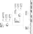
FIG. 2 is a block diagram illustrating an
一般に、システムに対する設計プロセスまたは設計段階中(開発プロセスまたは開発段階とも称される)に、通信ソフトウェアおよび/またはハードウェア構成要素からなるシステムを定義するためにSDMを活用する開発ツールが使用される。システム定義は、要求された資源、構成、動作特性、ポリシーなどを含めて、分散型システムを配置し、動作させるために必須のすべての情報を含んでいる。設計段階の完了後、システムを自動的に配置し、要求されるソフトウェアおよびハードウェア(例えば、サーバ、ストレージ、およびネットワーク)資源を動的に割り当て、構成するために配置段階でもシステム定義を使用することができる。異なるホスト環境および異なるスケールに配置するために同じシステム定義を使用することができる。 Generally, during the design process or phase of the system (also referred to as the development process or phase), development tools are utilized that leverage SDM to define the system of communication software and / or hardware components. . The system definition contains all the information necessary to deploy and operate a distributed system, including the required resources, configurations, operating characteristics, policies, etc. After completion of the design phase, the system is automatically deployed and the system definition is also used during the deployment phase to dynamically allocate and configure the required software and hardware (eg, server, storage, and network) resources. be able to. The same system definition can be used for deployment in different host environments and different scales.
アーキテクチャ200は、SDM定義モデルならびにSDM定義モデル内で機能動作を定義するスキーマを利用する。定義モデルは、「定義」と総称される様々な異なる種類のデータ構造を含む。SDMの機能は、アプリケーションプログラムインターフェース(API)のような1つまたは複数のプラットフォームサービスによって公開される。
The
システムの設計段階中、開発コンポーネント202はSDM文書204のようなシステム定義を含んでいる文書を生成する。開発コンポーネント202は、ワシントン州レッドモンドのMicrosoft(登録商標)社製のVisual Studio(登録商標)開発システムのような様々な開発コンポーネントのどれであってもよい。SDM文書204は、システムの配置(および、任意選択で管理)に関するすべての情報(本明細書では知識とも称する)を定義する。システムを配置し、またはシステムを管理するために必須の、またはその際に使用されるいかなる知識でもSDM文書204に含まれる。本明細書では単一文書として記載しているが、知識が複数の文書に展開され、保存され得ることを理解されたい。
During the design phase of the system, the
システム定義は、システムを1つまたは複数の資源、エンドポイント、関係(relationship)、およびサブシステムに関して定義する。システム定義はSDM文書(例えば、XML文書)で宣言される。資源はハードウェア資源であってもソフトウェア資源であってもよい。エンドポイントは複数のシステムを横断する通信(communication)を表す。関係は、システム、資源およびエンドポイント間の関連を定義する。サブシステムは完全なシステムとして取り扱うことができ、典型的には、より大きなシステムの一部である。 A system definition defines a system in terms of one or more resources, endpoints, relationships, and subsystems. The system definition is declared in an SDM document (for example, an XML document). Resources may be hardware resources or software resources. Endpoints represent communications across multiple systems. Relationships define the relationships between systems, resources, and endpoints. A subsystem can be treated as a complete system and is typically part of a larger system.
システム定義は、動的システムの基本構造を取り込む。システム定義は、すべての他の情報が追加されるスケルトンと見なすことができる。この構造は、通常、開発プロセス中に設計者および開発者によって指定され、通常、頻繁には変更されない。この構造に加え、SDMは、配置情報、インストールプロセス、構成用スキーマ、イベントおよび計測、自動タスク、ヘルスモデル、動作ポリシーなどを含むことができる。分散型システムの存続期間全体を通じて、他の情報を、オペレーションスタッフ、供給業者、および/または管理システムによって追加することができる。 The system definition captures the basic structure of the dynamic system. The system definition can be viewed as a skeleton to which all other information is added. This structure is usually specified by designers and developers during the development process and usually does not change often. In addition to this structure, the SDM can include configuration information, installation processes, configuration schemas, events and measurements, automated tasks, health models, operation policies, and the like. Throughout the life of the distributed system, other information can be added by operations staff, suppliers, and / or management systems.
SDM文書204は、システムが配置され、かつ/または実行される環境が充足しなければならないシステムの1つまたは複数の制約条件(要件とも称される)を含む。環境自体は、「論理インフラストラクチャ」(LIM)文書206、またはデータセンタ記述またはデータセンタモデルと称されるSDM文書を使用しても記述される。SDM文書204と類似して、LIM文書206は単一文書であっても、複数の文書によって構成されてもよい。LIM文書206は、開発コンポーネント202と類似のコンポーネントのような様々な開発コンポーネントのどれかを使用して生成することができる。LIM文書206は、開発コンポーネント202を使用して開発することもできる(すなわち、SDM文書204とLIM文書206の両方を生成するために同じ開発コンポーネントを使用することができる)。
LIM文書206によって記述された環境は、単一のコンピュータデバイスであっても、またはコンピュータデバイス(例えば、データセンタ)、アプリケーションホストなどの集合であってもよい。異なるシステムまたは同じシステムを異なる環境にインストールすることができる。例えば、データセンタは、50個のコンピュータデバイスを含むことができ、1つのシステムをそれらコンピュータデバイスのうちの5個に配置し、他のシステムをそれらコンピュータデバイスの35個に配置することができる。これらの要件は、システムが配置されるべき1つ以上のコンピュータデバイスに関するハードウェア要件(例えば、最低プロセッサ速度、最低メモリ量、ハードドライブ空き領域の最低量、使用可能なネットワーク帯域幅の最低量、使用可能な特定のセキュリティ機構など)、システムが配置されるべき1つ以上のコンピュータデバイスに関するソフトウェア要件(例えば、特定オペレーティングシステム、同様にインストールされなければならない1つまたは複数の他のアプリケーション、特定システムおよび/またはオペレーティングシステムを構成すべき方法に関する規定、使用されている特定の種類のセキュリティまたは暗号化など)、システムが配置されるべき1つ以上のコンピュータデバイスに関する他の要件(例えば、使用可能な特定のセキュリティキー、施行されるべきデータセンタポリシー、使用されている認証、環境トポロジなど)のような様々な形式を取ることができる。SDM文書204に記載されている単一システムを、別のLIM206に記載されているような複数の異なる環境に対して検証することができる。
The environment described by
要件は他の方向に向かうこともできる。すなわち、環境はインストールされるべきシステムの構成に関する(例えば、環境の標準またはポリシーを実施するための)制約条件または要件を有することができる。これらは、システムが有する必要のある特定の設定または構成、システムが提供またはサポートする必要のある特定機能、システムがサポートする必要のある特定のセキュリティ機構などのように、環境のオペレータによって作成される「明示的な」要件であってよい。これらは、環境の特定の構成によって生じる「潜在的な」要件であってもよい。例えば、環境内のホストコンピュータデバイスが特定の種類のファイルシステムを使用している場合、(別のファイルシステムを使用してそれらの同じアクションを実行することができたとしても)そのファイルシステムを使用していくつかのアクションを実行することができない場合がある。 Requirements can go in other directions. That is, the environment may have constraints or requirements (eg, to enforce environment standards or policies) on the configuration of the system to be installed. These are created by the environment's operators, such as the specific settings or configurations that the system must have, the specific features that the system needs to provide or support, the specific security mechanisms that the system needs to support, etc. It may be an "explicit" requirement. These may be "potential" requirements caused by a particular configuration of the environment. For example, if host computer devices in your environment use a particular type of file system, use that file system (even if you could use another file system to perform those same actions). You may not be able to perform some actions.
システムの設計段階中、検証コンポーネント208によって1つまたは複数の特定の環境に対してシステムを検証するためにSDM文書204を使用することができる。これは、システムが環境に対して検証され、環境がシステムに対して検証されるという双方向の検証である。検証コンポーネント208は、SDM文書204で特定された要件をLIM文書206に記載されている環境と比較し、要件のすべてがその環境によって満たされているか否かを判定することによって、システムに対して環境を検証することができる。検証コンポーネント208は、LIM文書206で特定された要件をSDM文書204に記載されているシステムと比較し、要件のすべてがそのシステムによって満たされているか否かを判定することによって環境に対してシステムを検証することができる。要件のすべてが環境およびシステムによって満たされている場合、設計者または開発者は、そのシステムをその環境に配置することができ、そこで作動すると分かる。しかし、要件のすべてが環境および/またはシステムによって満たされていない場合、検証コンポーネント208は満たされていない要件を設計者または開発者に通知することができ、したがってシステムがその環境に配置され、そこで作動するために、SDM文書204(同様にシステム)および/または環境にどのような変更を行う必要があるかが設計者または開発者に通知される。
During the design phase of the system, the
LIM文書206は、現実の環境またはシミュレートされた環境に関するものであってよい。現実の環境の場合、LIMは、現存しているあるいは既に記述されているがまだ施工されていない環境を記述する。例えば、現実の環境は現存するデータセンタであっても、既に設計済みであるがまだ実際には実施されていないデータセンタであってもよい。シミュレーションされた環境の場合、LIMは、必ずしも存在するとはいえないある予想された環境を記述する。現実の環境に対してはそのような仮定を行う必要はないが、予想された環境に関しては様々な仮定を行うことができる。通常、システムに対する設計プロセス中、LIM文書206はシミュレーションされた環境を記述する。しかし、現実の環境が特定の時点で存在する場合には、その環境を記述しているLIM文書206を設計段階中に使用することができる。
検証コンポーネント208は、開発中のシステムを配置することができるデータセンタから分離されている1つまたは複数のコンピュータデバイスであってよい。例えば、検証コンポーネント208は単一コンピュータデバイスであってよいが、あるいは検証の負担を複数のデバイス全体に分散してもよい。あるいはまた、検証コンポーネント208は、開発中のシステムが配置されるべきデータセンタのコンピュータデバイス102の1つまたは複数であってよい。
SDMは、横軸および縦軸にわたってシステムの機能の合成を可能にする。横軸に沿った合成はシステムおよびサブシステムによって行われる。縦軸に沿った合成は「層」によって行われる。アプリケーション、サービス、ネットワークトポロジ、およびハードウェアは、分散されたシステムで1つのロール(roll)を満たすが、典型的には独立して定義され、異なるチームまたは組織によって所有される。階層化は、ホスト上の一組の制約条件を定義する構成要素によって達成され、またその逆も行われる。 SDM allows for the synthesis of system functions across the horizontal and vertical axes. Synthesis along the horizontal axis is performed by systems and subsystems. The composition along the vertical axis is performed by "layers". Applications, services, network topologies, and hardware fulfill a roll in a distributed system, but are typically independently defined and owned by different teams or organizations. Tiering is achieved by components that define a set of constraints on a host, and vice versa.
図3は階層化設定例を示す。図3には、層302、層304、層306、および層308の4つの層が示されている。図3には4つの層が示されているが、実際の層の数は多様であってよく、4つより多くても少なくてもよい。さらに、異なる層の内容は異なる実施形態で異なっていてよい。図3を見ると分かるように、様々な層が他の層の上および/または下に位置する(例えば、層306は層304の上、層308の下にある)。
FIG. 3 shows a hierarchical setting example. FIG. 3 shows four layers:
1つの層内の異なるシステムおよびサブシステムはそれぞれ相互作用することができ、また異なる層のシステムおよびサブシステムとも相互作用することができる。例えば、層308のサブシステム310は層308のサブシステム312ならびに層306のサブシステム314と相互作用することができる。さらに、各層は1つ上の層に対する環境と見なすことができる。例えば、層306は層308のシステムおよびサブシステムに対する環境であり、層304は層306のシステムおよびサブシステムに対する環境である。各層302、304、306、および308はそれ独自の関連付けられたSDM文書を有する。
Different systems and subsystems within one tier can interact with each other, and can also interact with systems and subsystems at different tiers. For example,
異なる層302、304、306、および308は異なる内容を表すことができる。ある実施形態では、層302はハードウェア層であり、層304はネットワークトポロジおよびオペレーティングシステム層であり、層306はアプリケーションホスト層であり、層308はアプリケーション層である。ハードウェア層は、階層化されたシステム(例えば、図1のデバイス102)が構築される物理デバイス(例えば、コンピュータデバイス)を表す。ネットワークトポロジおよびオペレーティングシステム層は、コンピュータデバイスのネットワークトポロジ(例えば、図1のネットワーク設定100)ならびにそれらのコンピュータデバイスにインストールされたオペレーティングシステムを表す。アプリケーションホスト層は、他のアプリケーションをホストすることのできるコンピュータデバイス(例えば、SQLサーバ、IISなど)にインストールされたアプリケーションを表す。アプリケーション層は、他のアプリケーションをホストしないコンピュータデバイスにインストールされたアプリケーション(例えば、ゲームのような娯楽アプリケーション、ワードプロセッサのような生産アプリケーション、電子百科事典のようなレファレンスアプリケーション、ウェブサービスまたは経済分析のために使用することのできるような分散型アプリケーションなど)を表す。
The
図2に戻ると、アプリケーション開発者は開発コンポーネント202を使用してアプリケーションを設計し、開発することができる。開発者が自分のシステムの様々な部分およびそれらの部分の相互関係を定義すると、それらの部分および関係を取り込んだSDMファイル204が生成される。開発者は、LIMファイル206に記述されている環境に対してシステム記述を検証するために検証コンポーネント208を使用することができる。設計段階中のこの検証は「設計時検証」とも称される。
Returning to FIG. 2, an application developer can use the
以下の節「SDM実施態様例」で詳述するSDMは、分散システム(モデルシステム)の構成要素の構成、相互作用、および変更の記述をサポートするように設計されている。SDMはオブジェクト関係モデルに基づいている。「オブジェクト」はシステムに存在するエンティティを記述し、「関係」は様々なエンティティ間のリンクを示す。オブジェクトと関係は、SDMに関する意味情報を取り込むようさらに定義される。具体的には、オブジェクトは構成要素、エンドポイント、および資源に分割される。関係は、接続(通信とも称される)、包含、ホスティング、委託、およびレファレンスに分割される。オブジェクトおよび関係に関するさらなる詳細を後述する。 The SDM, detailed in the following section, “Example SDM Embodiments,” is designed to support the description of the configuration, interaction, and changes of the components of a distributed system (model system). SDM is based on an object relationship model. "Objects" describe the entities that exist in the system, and "relationships" indicate the links between the various entities. Objects and relationships are further defined to capture semantic information about the SDM. Specifically, objects are divided into components, endpoints, and resources. Relationships are divided into connections (also referred to as communications), containment, hosting, delegation, and references. Further details regarding objects and relationships are provided below.
SDMは、システム部分の共通カテゴリを提供し、広範囲のシステムにツールのサポートを提供し、設計時における定義チェックの基礎を提供する「抽象定義」を含む。一組の抽象定義は、サービス設計に対する包括的な基礎を提供する。「具体的定義」は実際のシステムまたはデータセンタ設計の部分を表す。具体的定義は、抽象定義を選択し、具体的定義のメンバおよびそのプロパティに対する設定値を定義するインプリメンテーションを定義することによって生成される。アプリケーションは、それらの具体的定義の集合を使用して生成される。 The SDM includes "abstract definitions" that provide a common category of system parts, provide tool support for a wide range of systems, and provide a basis for definition checking at design time. A set of abstract definitions provides a comprehensive basis for service design. "Specific definition" refers to a portion of an actual system or data center design. A concrete definition is created by selecting an abstract definition and defining an implementation that defines the settings for the members of the concrete definition and its properties. Applications are created using a set of those concrete definitions.
SDMは、関係のインスタンスが参加できる許可された関係の組に基づいてモデルが制限する「制約条件」も含んでいる。関係に関与するオブジェクトの構成によって異なる要件を記述する際に制約条件は有益である。例えば、通信プロトコルの各終端での参加者が互換性のあるセキュリティ設定を使用しているか否かを判定するために制約条件を使用することができる。 The SDM also includes "constraints" that the model restricts based on the set of allowed relationships that the instance of the relationship can participate in. Constraints are useful in describing different requirements depending on the composition of the objects involved in the relationship. For example, constraints can be used to determine whether participants at each end of the communication protocol are using compatible security settings.
LIMファイル206とSDMファイル204は、検証コンポーネント208のインターフェース/処理層210に入力される。インターフェース/処理層210はSDMファイル204の検証を制御する。検証コンポーネント208はコンパイラとも称することができる。
The
インターフェース/処理層210は、ローダ212、検証部214、およびシミュレータ218を含む。ローダ212はSDMファイル204を構文解析し、参照されるファイルまたはメモリ内型空間(in-memory type space)内の型をどれでもロードする。SDMファイル204はSDMクラス(例えば、XMLで)を定義し、ローダ212がそれをメモリ内型空間内のSDMクラスに変換する。検証部214は、ローダ212がSDMファイル204をロードするためにSDMファイル204が適切に書かれているか否かを検証して、SDMファイル204にエラーがあるか否かをチェックする。検証部214またはローダ212がエラーに遭遇した場合、エラーは、そのエラーの原因となった問題の表示を任意選択で含めて開発コンポーネント202に戻される。検証部214はさらに、設定値、型、およびSDMファイルレファレンスをチェックして型空間を「ウォーク(walk)」する。通常、検証部214またはローダ212がエラーに遭遇すると、設計時検証は中止される。
The interface /
次いでシミュレータ218は、後述するように、LIM文書206によって定義された環境をシミュレーションし、拡張エンジン220、フローエンジン222、および制約条件エンジン224を呼び出す。シミュレータ218が遭遇したいかなるエラーも、任意選択でそのエラーの原因となった問題の表示を含めてコンポーネント202に(例えば、結果226として)戻される。通常、シミュレータ218がエラーに遭遇した場合、そのエラーの表示は開発コンポーネント202に戻されるが、設計時検証は先に進む。
インターフェース/処理層210は、SDMファイル204の検証を実行するために拡張エンジン220、フローエンジン222、および制約条件エンジン224を呼び出す。一般に、拡張エンジン220は、要求されるすべての追加インスタンスおよびアクションを、バイバリューの子(by-value children)および関係を含めて追加するために、または適切なインスタンスおよび関係を除去するために、SDMファイル204に基づいてインスタンス空間を作成するためにそのアクションの組を拡張する。フローエンジン222はインスタンス「グラフ(graph)」上を「ウォーク」し、そのインスタンスに対して定義されたフローを見つけ、フローの値を適切な値に設定する。制約条件エンジン224はインスタンス空間上を「ウォーク」し、各制約条件メンバを見つけ、評価する。
The interface /
ある実施形態では、制約条件のすべてが真であると評価され(すなわち、制約条件のすべてが満たされ)、SDM文書204を処理する際に検証コンポーネント208がエラーに遭遇しない場合、検証コンポーネント208はSDM文書204にデジタル署名する。このデジタル署名は、SDM文書204が正常にコンパイルされたことを示している。様々な異なる方法のどの方法によってもSDM文書204にデジタル署名することができるが、これは、通常、SDM文書204に基づくデジタル署名と、検証コンポーネント208に関連付けられた公開/秘密鍵対とを生成を伴う。したがって、デジタル署名されたSDM文書は、(例えば、それらが配置される際に)既に検証されたものとして引き続き取り扱うことができる。デジタル署名されたSDM文書は、コンパイルされたSDM文書と称することもできる。
In some embodiments, if all of the constraints are evaluated to be true (ie, all of the constraints are satisfied) and the
様々な制約条件を評価することに加え、検証コンポーネント208は、それら参照された文書のフルネーム(および任意選択でバージョン)によって他のSDM文書へのレファレンスを更新することもできる。したがって、コンパイルされたSDM文書はそれらフルネームを含んでいる。例えば、SDM文書は別のSDM文書をインポートし、バージョンではなく名前によって当該他のSDM文書を参照することができ、検証コンポーネント208がその参照された文書をインポートする際、インポートされる文書のバージョンが特定され、コンパイルされたSDM文書に追加される。
In addition to evaluating various constraints, the
本明細書での説明は、SDM文書204に含まれる得る様々なメンバまたは定義を参照している。定義は、特定のインスタンスがインスタンス空間でどのように作成されるかを定義する。換言すれば、定義は何が実現可能かを定義する。メンバは定義に基づいて特定の用法またはシナリオを記述する。例えば、定義は特定のインスタンスには何が実現可能かを記述し、メンバはそれらの可能性のどれが特定のインスタンスに含まれるかを記述する。次の表に、メンバまたは定義の例ならびに各メンバまたは定義の要約を示す。
The description herein makes reference to various members or definitions that may be included in the

本明細書で検討するエンジンは、バイバリューメンバ(by value member)、バイレファレンスメンバ(by reference member)、拡張、リスナ(listener)、およびトップレベル定義を参照する。バイバリューメンバは、拡張中にインスタンスが自動的に作成されるメンバを参照する。ある実施態様では、バイバリューメンバは抽象であることはできない。バイレファレンスメンバは、拡張中に拡張エンジンによってインスタンスを自動的に作成することができないメンバである。逆に、拡張エンジンでイベントを待ち受けている外部ソースはインスタンスを作成する(例えば、インターフェース/処理層210はシミュレーション中にインスタンスを作成することができ、もしくはシミュレーション中または配置中にインスタンスを作成することを設計者または開発者に(例えば、ユーザインターフェースによって)照会することができる。)。
The engines discussed herein refer to by value members, by reference members, extensions, listeners, and top-level definitions. By value members refer to members whose instances are automatically created during expansion. In some embodiments, by-value members cannot be abstract. Bi-reference members are members that cannot be instantiated automatically by the extension engine during extension. Conversely, external sources waiting for events in the extension engine create instances (eg, the interface /
拡張は、ルートインスタンスが与えられた場合、そのルートインスタンスに関してインスタンス空間にデータが取り込まれるプロセスを参照する。ルートインスタンスのメンバのすべては反復的に作成される。バイレファレンスメンバは拡張エンジンによっては作成されず、外部ソースによって作成される。 An extension refers to the process by which data is populated into instance space for a root instance, given a root instance. All of the members of the root instance are created iteratively. Bi-reference members are not created by the extension engine, but by external sources.
イベントがトリガされた場合、リスナ(例えば、シミュレータ218)に通知される。そのようなイベントの一例は、バイレファレンスメンバを作成することの要求である。トップレベル定義は、SDM文書のルートレベルで定義された定義を参照する。SDM文書は、通常、トップレベル定義を1つだけ有しているが、別の実施形態では、SDM文書は2つ以上のトップレベル定義を有することができる。 If an event is triggered, a listener (eg, simulator 218) is notified. One example of such an event is a request to create a bi-reference member. The top level definition refers to the definition defined at the root level of the SDM document. An SDM document typically has only one top-level definition, but in other embodiments, an SDM document can have more than one top-level definition.
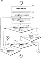
図4は、設計時検証のプロセス例400を示す流れ図である。プロセス400は、図2の検証コンポーネント208によって実施され、ソフトウェア、ファームウェア、ハードウェア、またはこれらの組合せで実行することができる。
FIG. 4 is a flowchart illustrating an
システムの作成、削除、または修正要求に応じて、SDM文書およびSDM文書に関連付けられた任意のレファレンスを(動作402)、任意選択でそのSDM文書をロードすることができることを検証する。ある実施形態では、1つ以上のLIM文書は既にロード済みとなっており、1つ以上のLIM文書によって記述された1つ以上のインスタンス空間が既に作成されている。しかし、これがまだ行われていない場合、動作402で1つ以上のLIM文書がロードされ、1つ以上のLIM文書によって記述された1つ以上のインスタンス空間が作成される。ある実施形態では、動作402でSDM文書をロードする前に、本明細書に記載のように1つ以上のLIM文書によって記述された1つ以上のインスタンス空間が拡張、フロー、および制約条件エンジンを使用して作成される。
In response to a request to create, delete, or modify the system, the SDM document and any references associated with the SDM document are verified (operation 402) to optionally load the SDM document. In some embodiments, one or more LIM documents have already been loaded, and one or more instance spaces described by the one or more LIM documents have already been created. However, if this has not been done yet,
次いで、SDM文書にエラーがあるか(動作404)またはSDM文書がロードされた際に型空間が作成されたか否かに関してチェックが行われる。動作404でのチェックとは、設計中のシステムではなく、SDM文書自体の構造またはフォーマットを対象としている。例えば、SDM文書のフォーマットが適切であること(例えば、文書が適切なXMLフォーマットであること)、またはSDM文書に未知の要素または型がないこと、またはSDM文書内の型レファレンスが有効であることなどを検証するために、動作404でチェックを行うことができる。エラーがある場合、それらエラーに関する表示が戻され(動作406)、処理400は終了する。これらのエラーは、例えば結果226として図2の開発コンポーネント202に戻すことができる。
A check is then made as to whether there is an error in the SDM document (act 404) or whether a type space was created when the SDM document was loaded. The check in
しかし、エラーがない場合、動作402でロードされたSDM文書のトップレベル定義が選択される(動作408)。ある実施形態では、SDM文書にはトップレベル定義が1つしかない。この場合、選択された定義に対するインスタンスが作成され(動作410)、インスタンス空間が拡張される(動作412)。トップレベル定義は、図4の拡張エンジン410によって実行される拡張の開始点として使用される。トップレベル定義を分析すること、ルートインスタンスの各メンバのインスタンスを作成すること、次いでそれら作成されたインスタンスのそれぞれを分析すること、それらのメンバのそれぞれに対する1つ以上のインスタンスを作成すること、等々によってインスタンス空間が拡張される。このプロセスは「拡張エンジン」という見出しで以下に詳述する。
However, if there are no errors, the top-level definition of the SDM document loaded in
トップレベル定義に基づく拡張が完了すると、拡張されたインスタンス空間のインスタンスに対して定義されたフローが特定され、フローの値が適切な値に設定される(動作414)。このプロセスは「フローエンジン」という見出しで以下に詳述する。 When the extension based on the top-level definition is completed, the flow defined for the instance in the extended instance space is identified, and the value of the flow is set to an appropriate value (operation 414). This process is detailed below under the heading "Flow Engine".
フローの評価による値が設定された後、制約条件がチェックされる(動作416)。インスタンス空間の各制約条件は、「制約条件エンジン」という見出しで以下に詳述するように制約条件チェックの一部として評価される。これらの制約条件は、通常、(LIM 206で記述されるように)システムが検証される対象であるシミュレーションされた環境の設定に対してチェックされる。 After the flow evaluation values are set, the constraints are checked (operation 416). Each constraint in the instance space is evaluated as part of a constraint check as detailed below under the heading "Constraints Engine". These constraints are typically checked against the settings of the simulated environment for which the system is to be verified (as described in LIM 206).
制約条件チェックが完了すると、未選択のSDM文書に追加のトップレベル定義があるか否かに関してチェックされる(動作418)。SDM文書に1つまたは複数の追加のトップレベル定義がある場合、それら追加のトップレベル定義のうちの1つが選択され(動作420)、処理は動作410に戻され、選択されたトップレベル定義のインスタンスがそこで作成される。
Once the constraint check has been completed, a check is made as to whether any unselected SDM documents have additional top-level definitions (operation 418). If there is one or more additional top-level definitions in the SDM document, one of the additional top-level definitions is selected (operation 420) and processing returns to
しかし、未選択のトップレベル定義がない場合、エラーが検出されたか否かに関してチェックされる(動作422)。動作422のエラーとは、動作412の拡張、動作414のフロー、動作416の制約条件チェック中に生成されたエラーおよび/または警告のことである。エラーまたは警告がある場合、それらのエラーまたは警告に関する表示が戻され(動作406)、処理400が終了する。これらのエラーは、例えば結果226として図2の開発コンポーネント202に戻すことができる。
However, if there are no unselected top-level definitions, a check is made as to whether an error was detected (operation 422). The error of
しかしエラーがない場合、図4の設計時検証プロセスは成功であり、成功の表示が戻される(動作424)。成功の表示は、例えば結果226として図2の開発コンポーネント202に戻すことができる。
However, if there are no errors, the design-time verification process of FIG. 4 is successful and an indication of success is returned (operation 424). An indication of success can be returned to
動作406で開発コンポーネント202にエラーおよび/または警告を戻すことによって、または動作424で成功の表示を戻すことによって、SDM文書204に記述されたシステムの設計時検証の結果が開発コンポーネント202に戻される。これらのエラーおよび/または警告もしくは成功の表示は、開発コンポーネント202を使用する設計者にも提示することができる。これにより、設計者に、設計中の(および、SDM文書204に記述された)システムが検証済みであるか否か、または潜在的な問題があるか否かを通知することができる。設計者に特定のエラーおよび/または警告の表示を戻すことによって、潜在的な問題が何であるか、その問題を解決する方法(または、それらを解決する必要さえあるか否か)を設計者により詳細に知らせることができる。このフィードバックは設計プロセス中に設計者に提供することができるが、これは設計者に、設計したシステムに問題があることが判明する前にデータセンタでシステムを配置するよう試みることを要求しない。
The results of the design-time verification of the system described in the
シミュレーション
上述のように、図2のインターフェース/処理層210は、LIM文書206に記述されている環境をシミュレートする。これによって、SDM文書204によって記載されたシステムをシステム設計中に予測された環境に対して検証することができ、環境に対してシステムを配置する前にエラーを特定することが可能になる。
Simulation As described above, the interface /
インスタンス空間内の多くのインスタンスは、以下で詳述するように拡張エンジンによって作成することができる。しかしそれらインスタンスのいくつかは、拡張エンジンでなくシミュレータ218によって作成される。ある実施形態では、シミュレータ218によって作成されたインスタンスはトップレベル定義およびバイレファレンスメンバである。ある実施態様では、各トップレベル定義はそれ独自のインスタンス空間でシミュレーションされる。
Many instances in the instance space can be created by the extension engine, as described in more detail below. However, some of those instances are created by the
シミュレータ218は、コンパイル中の文書のルートで見つかった定義の2つのカテゴリである(1)システム定義と、(2)ホストおよびゲストがシステム定義であるホスティング定義とをシミュレーションする。これら定義の2つのカテゴリは、大半がシミュレータ218によってインスタンスを作成することができるスタンドアロン定義である。他の定義は、一般に他の定義のコンテキストで使用されるだけであり、したがって拡張エンジン220によって作成される。ある実施形態では、シミュレータ218は、通常はあったとしてもほとんど意味のない検証を生じるような抽象定義はシミュレーションしない。
システム定義は、定義に対するインスタンスを作成し、そのインスタンスをインスタンス空間のルートインスタンスとして追加することによってシミュレーションされる。次いでそのインスタンスのメンバおよびネストされたメンバが、拡張エンジン220を呼び出すことによってインスタンス生成される。
A system definition is simulated by creating an instance for the definition and adding that instance as the root instance in the instance space. The members of the instance and the nested members are then instantiated by calling the
ホスティング定義のシミュレーションは、ホストとゲストの間の検証を提供する。ある実施形態では、ホスティング関係のインスタンスはルートインスタンスとしては使用されず、したがって拡張エンジンが呼び出される前に特別なルートインスタンスが作成される。この特別なルートインスタンスは、3つのメンバである、(1)ホスティング関係のホストに対するシステム定義と、(2)ホスティング関係のゲストに対するシステム定義と、(3)最初の2つのメンバのホストおよびゲストシステム定義のインスタンスに関連付けられたホスティング定義とを有するシステム定義である。次いで拡張エンジン222は、特別なルートインスタンスのメンバおよびネストされたメンバをインスタンス生成するために呼び出される。
Simulation of the hosting definition provides verification between the host and the guest. In some embodiments, instances of the hosting relationship are not used as root instances, so a special root instance is created before the extension engine is called. This special root instance has three members: (1) a system definition for the host in the hosting relationship, (2) a system definition for the guest in the hosting relationship, and (3) the host and guest system of the first two members. A system definition having a hosting definition associated with an instance of the definition. The
作成すべきインスタンス数は未知であり、配置環境によって異なるので、拡張エンジン220はバイレファレンスメンバのインスタンスは作成しない。さらに、バイレファレンスメンバは抽象である場合があり、したがってメンバをインスタンス生成するために使用される具体的定義は未知である。配置中にこれらの質問に回答するために人的介入(例えば、システム管理者による)が通常利用される。このような介入は任意選択で設計時検証中にも利用することができる。しかし、より一般的には、インターフェース/処理層210(例えば、シミュレータ218)は、次の通りに人間のオペレータが何を選ぶかをシミュレーションし、これはシミュレーション中の人間のオペレータの介入へのいかなる要求をも緩和する。シミュレータ218は、1つまたは最小発生数よりも大きなメンバのインスタンス数を作成する(例えば、バイレファレンスメンバのためにパラメータMinOccursで指定されたように)。バイレファレンスメンバが抽象である場合、シミュレータ218はそのメンバのインスタンスは生成せず、情報を伴う(例えば、抽象バイレファレンスメンバをシミュレーションできないことを示す)警告をユーザに戻す。
Since the number of instances to be created is unknown and varies depending on the deployment environment, the
拡張エンジン
拡張エンジン220は幅広いコマンドを検証コンポーネント208に入力することを可能とし、それらのコマンドの影響を受ける適切なオブジェクトおよび関係を特定するためにそれらのコマンドを拡張する。通常、これら多様なコマンドは、特定のオブジェクトまたは関係を作成または削除するためのコマンドである(例えば、ウェブアプリケーションを作成するためのコマンド、またはウェブアプリケーションを削除するためのコマンド)。拡張エンジン220は、バイバリューの子および関係を含めて要求されるすべての追加インスタンスおよび関係を追加し、または適切なインスタンスおよび関係を除去するために、SDMファイル204に基づくインスタンス空間を作成するためにそのアクションの組を拡張する。
Expansion engine
The
最初、シミュレーション中にトップレベル定義のインスタンス(トップレベルインスタンスとも称される)が作成された後、インスタンス空間にデータを取り込むために拡張エンジン220が呼び出される。ルートインスタンスが拡張の開始位置として拡張エンジン220に渡される。拡張によって作成されたインスタンスはルートインスタンスと関係している。拡張エンジン220が特定のインスタンス空間に対して呼び出された最初の時点で、拡張エンジン220に渡されたルートインスタンスはトップレベルのインスタンス(トップレベル定義のインスタンス)である。しかし拡張エンジン220は、通常はそうであるが、繰り返し呼び出される場合がある。したがって、トップレベルインスタンスのメンバおよびネストされたメンバはそのような反復呼び出しのルートインスタンスとなる。
Initially, after an instance of the top-level definition (also referred to as a top-level instance) is created during the simulation, the
拡張エンジン220は、ルートインスタンスの各メンバの1つ以上のインスタンスを作成することから開始する。各メンバがインスタンス生成されると、それらはネストされたメンバに対して検査される。別のメンバ内で定義されているメンバは、当該他のメンバ内にネストされているものと称される。メンバのネスティングは複数レベルを通して行うことができる(例えば、メンバはその中にネストされた複数のメンバを定義することができ、それら複数のメンバのそれぞれはその中にネストされた複数のメンバを定義することができ、さらにそのそれぞれがその中にネストされた複数のメンバを定義することができ、...という具合に)。拡張プロセスは、インスタンス空間がルートインスタンスに関して完全に作成されるまでメンバおよびネストされたメンバのそれぞれに対して反復的に実行される。
The
ある実施形態では、拡張中に様々な型のメンバの1つの部分集合だけがインスタンス生成される。拡張中に作成されるインスタンスのこの部分集合は、次のオブジェクトメンバ、すなわちサブシステムと、資源と、エンドポイントとを含む。拡張中に作成されたインスタンスのこの部分集合は、次の関係メンバ、すなわち包含と、通信と、ホスティングと、委任と、レファレンスも含む。この部分集合に含まれない他のメンバは拡張によってはインスタンス生成されず、上記のインスタンスの1つが拡張によって作成された際に作成プロセスがメンバまたは定義を検査し、当該他のメンバに対する子メンバのインスタンスを自働的に作成する。当該他のメンバの例としては、フローメンバと制約条件メンバとが含まれる。 In some embodiments, only one subset of members of various types is instantiated during expansion. This subset of instances created during extension includes the following object members: subsystem, resource, and endpoint. This subset of instances created during the extension also includes the following relationship members: containment, communication, hosting, delegation, and references. Other members not included in this subset are not instantiated by the extension, and the creation process examines the member or definition when one of the above instances is created by the extension, and the child members of the Create an instance automatically. Examples of the other members include a flow member and a constraint member.
ある実施形態では、拡張エンジン220が呼び出された際にメンバのインスタンスが既に存在する場合、そのインスタンスは再度作成されない。しかしインスタンス空間が完全に作成されたこと(また、まだ作成されていないネストされたメンバをこの反復的な呼び出しから作成すること)を検証するために拡張エンジン220は各インスタンスに対して反復的に進む。
In some embodiments, if an instance of the member already exists when the
図5Aおよび5Bは、インスタンス空間を作成する反復拡張プロセス例500を説明する流れ図である。インスタンス空間は、図2のSDM文書204のようなSDM文書によって定義される。プロセス500は、図2の拡張エンジン220によって実施されるが、ソフトウェア、ファームウェア、ハードウェア、またはこれらの組合せによって実行することができる。
5A and 5B are flowcharts illustrating an example
最初にインスタンス定義がアクセスされる(動作502)。呼び出されると、拡張エンジン220には拡張されるべきインスタンス定義が通知され(本節で既に説明したルートインスタンス)、動作502でこのインスタンス定義がアクセスされる。拡張エンジン220にはインスタンス定義を渡すことができ、インスタンス定義のある場所の識別子(例えば、ポインタ)を渡すことができ、またはインスタンス定義にアクセスすることができる場所および/またはその方法を通知することができる。プロセス500は、トップレベル定義であるインスタンス定義を使用してシミュレータ218によって呼び出すか、またはプロセス500自体によって反復的に呼び出すことができる。
First, the instance definition is accessed (act 502). When invoked, the
次いでインスタンス定義のメンバが選択される(動作504)。メンバはインスタンス定義からいかなる順番でも選択することができるが、通常はインスタンス空間を定義するSDMファイルにある順番で選択される。ある実施形態では、関係メンバが選択される前にすべてのオブジェクトメンバが選択される。 A member of the instance definition is then selected (operation 504). Members can be selected in any order from the instance definition, but are usually selected in the order in which the SDM file defines the instance space. In some embodiments, all object members are selected before the relationship members are selected.
選択されたメンバがオブジェクトメンバか関係メンバかに関して次いでチェックされ(動作506)、このチェックの結果に基づいてプロセス500は進む。選択されたメンバがオブジェクトメンバの場合、作成中のインスタンス空間には選択されたメンバの正確な数のインスタンスが既にあるか否かに関してチェックされる(動作508)。各メンバは、メンバのインスタンスをいくつ作成すべきかに関する表示を含む。ある実施形態では、メンバがより多くのインスタンスを作成するよう指定しない限り(メンバに明示的に指定されているか否かにかかわらず)各メンバの1つのインスタンスが作成されるように、1つのインスタンスというディフォルト値が使用される。
A check is then made as to whether the selected member is an object member or a related member (operation 506), and the
正確な数のインスタンスがまだ存在していない場合、オブジェクトメンバがバイバリューメンバであるか否かに関してチェックされる(動作510)。オブジェクトメンバがバイバリューメンバである場合、メンバ定義で指定されているようにオブジェクトの最小発生数が作成される(動作512)。しかしオブジェクトメンバがバイバリューメンバでない場合、それはバイレファレンスメンバであり、したがってリスナ(例えば、図2のシミュレータ218)がバイレファレンスメンバのインスタンスを作成することを可能にするイベントがトリガされる(動作514)。
If the exact number of instances does not already exist, a check is made as to whether the object member is a by-value member (operation 510). If the object member is a by-value member, a minimum occurrence of the object is created as specified in the member definition (operation 512). However, if the object member is not a bi-value member, it is a bi-reference member, and thus an event is triggered that allows a listener (eg,
オブジェクトメンバの1つ以上のインスタンスが動作512と514のいずれにかかわらず作成された後、または動作508でメンバの正確な数のインスタンスが既に存在すると判定された場合、プロセス500は動作516に進む。動作516で、動作512または動作514で作成された1つ以上のインスタンス(または、動作508で既に作成されたと判定された1つ以上のインスタンス)の各メンバインスタンスのためにプロセス500が呼び出される。プロセス500を反復的に呼び出す場合、プロセス500が呼び出された各メンバインスタンスは呼び出されたプロセス500に対するインスタンス定義となる。したがって、インスタンス空間ですべてのインスタンスが作成されるまでプロセス500はオブジェクトメンバで反復的に呼び出される。
After one or more instances of the object member have been created irrespective of
さらに、動作504で選択されていなかったインスタンス定義に追加メンバがあるか否かに関してチェックがなされる(動作518)。インスタンス定義に1つまたは複数のそのような追加メンバがある場合、プロセス500は動作504に戻り、それらメンバのうちの1つがそこで選択される。しかしインスタンス定義にそのような追加メンバがない場合、プロセス500はこのインスタンス定義については完了している。
Further, a check is made as to whether there are additional members in the instance definition that were not selected in operation 504 (operation 518). If there is one or more such additional members in the instance definition,
動作506に戻って、選択されたメンバが関係メンバである場合、プロセス500は関係に関与するソースインスタンス数とターゲットインスタンス数とに基づいて作成すべき関係インスタンス数を特定する(図5Bの動作522)。作成すべき関係インスタンス数は、ソースインスタンス数にターゲットインスタンス数を乗じ、その結果を作成すべき関係インスタンス数とすることによって決定される。次いで、関係の特定された数のインスタンスが作成される(動作524)。
Returning to
あるいは、ソースインスタンス数にターゲットインスタンス数を乗じることによって関係インスタンスの最大数を得ることができ、動作524でその最大数の部分集合を作成することができる。例えば複数の実現可能なホストが存在する場合、動作524でそのうちの1つだけを選択することができる。上記のバイレファレンスメンバと同様に、関係インスタンスの部分集合を選択するためにリスナ(例えば、人間のオペレータまたはシミュレータ218)を呼び出すことができる。シミュレータ218は、例えば関係インスタンスのどの部分集合を作成するかを決定するために使用されるべき様々な基準または従うべき規則によって構成またはプログラムすることができる。
Alternatively, the maximum number of relationship instances can be obtained by multiplying the number of source instances by the number of target instances, and a subset of the maximum number can be created at
関係メンバの型に応じて関係インスタンスは様々な方法で作成される。ある実施形態では、包含定義メンバ、通信定義メンバ、レファレンス定義メンバ、ホスティング定義メンバ、および委任定義メンバという型の関係メンバを使用することができる。包含定義メンバは、親を子メンバの各インスタンスに関連付ける1対多の関係である。包含定義メンバは、1つのオブジェクトメンバを他のオブジェクトメンバに含めることができることを記述している。通信定義メンバは、サーバとクライアントメンバインスタンスのすべての組合せを関連付ける多対多の関係である。通信定義メンバは、別個に配置されたソフトウェア要素間の相互作用を記述する。レファレンス定義メンバは、ソースメンバインスタンスに依存するすべての組合せを関連付ける多対多の関係である。レファレンス定義メンバは、(ホスティング定義メンバに加えて)インスタンス間の従属関係を取り込むために使用される。これらの従属関係は、例えば配置中の構築順番とインストールおよび更新中のシステム間のフローパラメータとを制御するために使用することができる。ホスティング定義メンバは、ホストをそのゲストのメンバインスタンスのそれぞれに関連付ける1対多の関係である。ホスティング定義メンバは、構築されるためにゲストがホストを必要とすることを特定するために使用される。委任定義メンバは、2つのシステムの通信エンドポイントを関連付ける1対1の関係である。委任定義メンバは、1つのシステムから別のシステムに動作を転送するために使用される(例えば、既に指示されているすべての相互作用を1つのシステムから別のシステムのエンドポイントに転送する)。 Relationship instances are created in various ways depending on the type of the relationship member. In some embodiments, relationship members of the types inclusion definition member, communication definition member, reference definition member, hosting definition member, and delegation definition member can be used. Inclusion definition members are one-to-many relationships that associate a parent with each instance of a child member. The inclusion definition member describes that one object member can be included in another object member. Communication definition members are many-to-many relationships that associate all combinations of server and client member instances. The communication definition member describes the interaction between separately deployed software elements. The reference definition member is a many-to-many relationship that associates all combinations that depend on the source member instance. Reference definition members are used to capture dependencies between instances (in addition to hosting definition members). These dependencies can be used, for example, to control the build order during deployment and flow parameters between systems during installation and updates. A hosting definition member is a one-to-many relationship that associates a host with each of its guest member instances. The hosting definition member is used to specify that a guest needs a host to be built. Delegation definition members are one-to-one relationships that link the communication endpoints of two systems. Delegation definition members are used to transfer actions from one system to another (eg, transfer all previously directed interactions from one system to endpoints of another system).
関係の各インスタンスに関して、ソースおよびターゲットインスタンスが関係のインスタンスに関連付けられる(動作526)。次いでプロセス500は図5Aの動作518に戻り、インスタンス定義に選択されるべき追加メンバがあるか否かに関してそこでチェックがなされる。
For each instance of the relationship, a source and target instance is associated with the instance of the relationship (operation 526).
したがって、プロセス500は反復的に呼び出され、プロセスが反復的に呼び出されるたびに様々なオブジェクトおよび関係インスタンスが作成される。反復拡張プロセスは、すべてのメンバインスタンスが作成された際にインスタンス空間の作成が何時完了したかを認識している。
Thus, the
拡張プロセスの反復的な性質により、結果として生じたインスタンスは、図2のフローエンジン222および制約条件エンジン224へのエントリポイントであるトップレベルのインスタンスによって相互にリンクされる。このようにして作成されたインスタンス空間は、ツリーの各ノードがメンバインスタンスを表すインスタンスツリーと見なすことができる。さらに、ツリーの各ノード(トップレベルのノードを除いて)は、ツリーのノードを作成するために拡張プロセスを呼び出したメンバインスタンスを表す親ノードにリンクされる。さらにツリーの各ノードは、ツリーのそのノードのメンバインスタンスのメンバである0またはそれより多い子ノードにリンクされる。リーフメンバがネストされたメンバを有しない場合(例えば、すべてのリーフメンバが0個の子ノードを有する場合)、反復拡張プロセスはインスタンスグラフの作成が完了したことを認識している。さらに、その型であるメンバを有する定義により拡張プロセスが無限になる可能性がある状況を避けるために、ある実施形態では、定義が祖先インスタンスとしてまだインスタンス生成されていない場合、拡張プロセスはインスタンスを作成することしか選ばない。例えばディレクトリの定義があり、それが中にディレクトリを有する場合、単一ディレクトリがあるならば拡張エンジンはこれの拡張を停止する。
Due to the iterative nature of the extension process, the resulting instances are linked together by a top-level instance that is the entry point to flow
フローエンジン
拡張エンジン220が拡張プロセスを完了した後、シミュレータ218は拡張プロセスから生じたインスタンス空間に対してフローエンジン222を呼び出す。フローエンジン222は、インスタンス空間のインスタンスグラフ上を「ウォーク」し、インスタンスグラフで定義されたフローインスタンスを見つける。次いでフローエンジン222はフローの値を適切な値に設定する。
Flow engine
After the
設定はSDMファイル204の定義に対して宣言することができ、対応する設定値はそれらの定義から作成されたインスタンス上に存在することができる。設定値(setting values)は非計算設定値(non-calculated values)であっても、計算設定値(calculated setting values)であってもよい。
Settings can be declared for the definitions in the
非計算設定値は、(例えば、SDMファイル204の)定義からのディフォルト値または初期値によって設定された設定値であるか、または値を明示的に設定するユーザによって設定された設定値である。非計算設定値は、それらが属するSDMインスタンスの作成に対してだけ設定されるよう制限されても、SDMインスタンスの存続期間を通して変更されてもよい。非計算設定値は、フローの出力ではなく、フローへの入力として動作することができる。 Non-calculated settings are settings set by default or initial values from the definition (eg, of SDM file 204) or settings set by a user that explicitly sets the value. Non-computed settings may be restricted to be set only for the creation of the SDM instance to which they belong, or may change throughout the life of the SDM instance. Non-calculated settings can act as inputs to the flow, rather than outputs of the flow.
計算設定値は、フローの出力である設定値である。その結果、フローは計算設定値の値を設定することができるが、一般に他のエンティティは設定できない。ある実施態様では、特定の計算設定値に値を供給する1つのフローしかない場合がある。そのような実施態様では、複数のフローが同じ設定値インスタンスに出力する場合、エラーが報告され、フローの出力がエラー状態に設定される。計算設定値は1つまたは複数の入力に基づいている。これらの入力は計算設定値および/または非計算設定値であってよい。 The calculation set value is a set value that is an output of the flow. As a result, the flow can set the value of the calculated setting, but generally cannot set other entities. In some embodiments, there may be only one flow that supplies a value for a particular calculated setting. In such an embodiment, if multiple flows output to the same setpoint instance, an error is reported and the output of the flow is set to an error state. The calculated settings are based on one or more inputs. These inputs may be calculated settings and / or non-calculated settings.
ある実施形態では、計算設定値は、構成値と非構成値という2つのカテゴリに分離することができる。構成値はフローによって計算される値であり、その結果、それらを含むSDMインスタンスの構成が得られる。例えば、ファイルまたはデータベース名へのフルパスは構成値である。 In some embodiments, the calculated settings can be separated into two categories: configuration values and non-configuration values. The configuration values are the values calculated by the flow, resulting in the configuration of the SDM instance containing them. For example, the full path to the file or database name is a configuration value.
非構成値はフローによって計算された値だが、これから構成は得られない。むしろ、これらは制約条件に交換された値としてのみ存在する。例えば、この結果得られたすべての継承したweb.config値を考慮するweb.config設定は非構成値である。非構成値の別の例は、この結果として得られた、ファイルの構成されたアクセス制御リストならびにファイルが含んでいるディレクトリおよびボリュームを考慮したファイルのアクセス制御リストである。 Non-configured values are values calculated by the flow, but no configuration can be obtained from them. Rather, they only exist as values exchanged into constraints. For example, all the inherited web. web. considering the config value. The config setting is a non-configured value. Another example of a non-configured value is the resulting structured access control list of the file and the access control list of the file taking into account the directories and volumes it contains.
フローエンジン222は、任意選択で構成値と非構成値とを別個に取り扱うことができる。例えば、構成値に高い優先順位を与えることができ、したがって構成値を設定するフローを、非構成値を設定するフローの前に評価することができる。
The
一般に、インスタンス空間内のフローインスタンスを特定し、フローインスタンスへの入力の値を特定する(例えば、それらの入力のソースである他のインスタンスの設定値を特定する)ことによってフローは評価される。命令のモジュールまたは組はフローインスタンスによって参照されるが、その命令のモジュールまたは組はフローインスタンスに対応するフロー機能を処理することができる。フロー機能は入力の値に基づいて処理され、そのフロー機能の結果が得られる。フロー機能の結果はフローインスタンスの出力として設定される。1つのフローは0またはそれを超える入力値と1つまたは複数の出力とを有することができる(例えば、1つまたは複数のインスタンスに対する設定値をフローの出力に基づいて設定することができる)。 Generally, flows are evaluated by identifying flow instances in the instance space and identifying the values of inputs to the flow instances (eg, identifying the settings of other instances that are the sources of those inputs). A module or set of instructions is referenced by a flow instance, but the module or set of instructions can handle a flow function corresponding to the flow instance. The flow function is processed based on the value of the input, and the result of the flow function is obtained. The result of the flow function is set as the output of the flow instance. A flow can have zero or more input values and one or more outputs (eg, settings for one or more instances can be set based on the outputs of the flow).
幅広い種類のフロー機能のどれでも使用することができる。フロー機能はシステムの開発者および/または他の関係者によって定義することができる。例えばSDNファイル204を作成しているのと同じ設計者が1つまたは複数のフロー機能を定義することができる。別の例として、開発コンポーネント202の製造業者またはある種の他のサードパーティ開発者が1つまたは複数のフロー機能を定義することができる。フロー機能自体は、代数、幾何、微積分などを利用する計算、日付および/または時刻に基づく計算、乱数計算などのような様々な計算および/または動作のどれでも含むことができる。
Any of a wide variety of flow functions can be used. The flow function can be defined by the system developer and / or other parties. For example, the same designer creating the SDN file 204 can define one or more flow functions. As another example, the manufacturer of the
ある実施形態では、SDMファイル204で定義されたフローメンバがマネージャ定義に関連付けられている。マネージャ定義は、フロー機能を処理するために実行することができる一組の命令またはコードへのポインタを含む。したがって、フローインスタンスに対するフローを評価するために、関連付けられたマネージャ定義が特定され、関連付けられたマネージャが(まだインスタンス生成されていない場合は)インスタンス生成される。当該一組の命令またはコードへのポインタがマネージャから得られるが、これはフロー出力を決定するために当該一組の命令またはコードを得て、実行することを可能にする。 In some embodiments, the flow members defined in SDM file 204 are associated with a manager definition. The manager definition includes a pointer to a set of instructions or code that can be executed to handle the flow function. Thus, to evaluate the flow for a flow instance, an associated manager definition is identified and the associated manager is instantiated (if not already instantiated). A pointer to the set of instructions or codes is obtained from the manager, which allows the set of instructions or codes to be obtained and executed to determine the flow output.
さらにある実施形態では、マネージャは型変換をサポートすることもできる。このような実施形態では、マネージャは、フローを異なる型の2つ以上の設定値に基づかせることができる。例えば、入力値は出力値と異なる型であってよい。マネージャは、そのような型の変換を行うことを可能にする1つまたは複数の方法を公開するか、または変換を実行するために取得し実行されるべき一組の命令またはコードへのポインタを含む。異なる変換を異なるマネージャによってサポートすることができる(例えば、マネージャ設計者は、所望の型の変換ならどれでもサポートするようマネージャを設計することができる)。 Further, in some embodiments, the manager may support type conversion. In such an embodiment, the manager may base the flow on two or more different types of settings. For example, the input value may be of a different type than the output value. The manager may expose one or more methods that allow such type conversions to be performed, or may provide a pointer to a set of instructions or code to be obtained and executed to perform the conversion. Including. Different transformations can be supported by different managers (eg, a manager designer can design a manager to support any desired type of transformation).
図6Aおよび6Bは、評価フローのためのプロセス例600を示す流れ図である。プロセス600は、図2のフローエンジン222によって実施され、ソフトウェア、ファームウェア、ハードウェア、またはこれらの組合せで実行することができる。
6A and 6B are flowcharts illustrating an
最初に、インスタンス空間のインスタンスのすべての設定が見つけられる(動作602)。これらの設定は、インスタンスグラフの各ノードを設定値に関してチェックすることによるような様々な方法で見つけることができる。次いでインスタンス空間のすべてのフローインスタンスが特定される(動作604)。インスタンス空間の各フローインスタンスは「ダーティ」および「訪問なし」とマーク付けされる(動作606)。「ダーティ」というマーク付けは、フローがまだ実行されていないか、または評価されていないことを示している。「訪問なし」というマーク付けは、フローの実行または評価がまだ開始されていないということを示している。フローインスタンスのマーク付けは、幅広い様々な方法で実行することができる。例えば、各フローインスタンスは、フローインスタンスを「ダーティ」とマーク付けするよう設定ができる「ダーティ」フラグと、フローインスタンスを「訪問なし」とマーク付けするよう設定できる「訪問なし」フラグとを有することができる。他の例として、フローエンジン222は、リスト、表、またはエンジン222がフローインスタンスの記録およびそれらの関連付けられたマーク付けを保持することができる1つ以上の他のデータ構造を維持することができる。
First, all settings for the instance in the instance space are found (operation 602). These settings can be found in various ways, such as by checking each node in the instance graph for settings. Then, all flow instances in the instance space are identified (act 604). Each flow instance in the instance space is marked "dirty" and "no visit" (operation 606). Marking "dirty" indicates that the flow has not yet been executed or evaluated. Marking "no visit" indicates that the execution or evaluation of the flow has not yet started. Marking a flow instance can be performed in a wide variety of ways. For example, each flow instance should have a "dirty" flag that can be set to mark the flow instance as "dirty" and a "no visit" flag that can be set to mark the flow instance as "no visit" Can be. As another example,
フローインスタンスの結果として値を受け取る設定が次いで特定される(動作608)。動作608で、計算された設定値のすべてが特定される。これらの設置自体は、それらが計算設定値であるかまたは非計算設定値であるかを示している(例えば、それらが非計算設定値であることを示すよう設定することができる「固定」属性のようなフラグまたは属性を有することができる)。動作608では、値の従属関係を示す従属関係グラフを任意選択で生成することもできる。従属関係グラフは、各設定値に関して、他のどの設定値にそれが依存しているか(すなわち、その入力である他の設定値)と他のどの設定値がそれに依存しているか(すなわち、それを入力として使用する他の設定値)とを示す。
Settings that receive values as a result of the flow instance are then identified (act 608). At
動作604で「ダーティ」および「訪問なし」とマーク付けされていると特定されたフローインスタンスのうちの1つが次いで選択される(動作610)。フローインスタンスは、動作604でフローインスタンスが特定された順番に基づく順番、無作為な順番、入力値の番号に基づく順番などのようなどのような順番でも選択することができる。選択されたフローインスタンスは、次いで「訪問あり」とマーク付けされるが、依然として「ダーティ」とマーク付けされたままである(動作612)。これは、フローインスタンスに関連付けられたフローの評価または実行は開始されたが、そのフローはまだ実行も評価もされていないということを示している(例えば、フローに対する出力値はまだ決定されていない)。
One of the flow instances identified as being marked "dirty" and "no visit" in
次いでフローインスタンスに対する入力が特定される(動作614)。各フローインスタンスは、その入力のそれぞれに対するソース(例えば、別のインスタンスの特定の設定値)を特定するパラメータを有する。特定された入力にまだ値が割り当てられていないか否かに関するチェックが次いで行われる(図6Bの動作616)。非計算設定値である入力は、既に評価済みのフローインスタンスによって計算された計算設定値である入力がそうであるように、割り当てられた値となっている。しかし未評価のフローインスタンスによって計算された計算設定値にはまだ値は割り当てられていない(例えば、それらはヌル値を有する場合がある)。 The input for the flow instance is then identified (operation 614). Each flow instance has parameters that specify the source for each of its inputs (eg, specific settings of another instance). A check is then made as to whether the identified input has not yet been assigned a value (operation 616 of FIG. 6B). An input that is a non-calculated set value is an assigned value, as is an input that is a calculated set value calculated by a flow instance that has already been evaluated. However, the calculated settings calculated by the unevaluated flow instances have not yet been assigned a value (eg, they may have a null value).
特定された入力の1つまたは複数に割り当てられた値がない場合、(動作610で選択された)このフローインスタンスの評価は中断される(動作618)。入力値の計算を可能とするために評価が中断される。まだ値を有さない各入力に対して、入力値を設定するフローインスタンスが特定される(動作620)。次いでプロセス600は、そのフローインスタンスの評価を開始するために図6aの動作612に戻る(動作622)。次いで入力のすべてが値を有すると、動作618で中断されたフローインスタンスの評価が再開される(動作624)。例えば後述する動作616または動作626で、評価を再開することができる。動作620で特定されたフローインスタンスの1つまたは複数の評価自体は、まだ値を有していない特定された入力のために中断する場合があることに留意されたい。
If there is no value assigned to one or more of the identified inputs, evaluation of this flow instance (selected in operation 610) is suspended (operation 618). The evaluation is interrupted to allow the calculation of the input value. For each input that does not yet have a value, the flow instance that sets the input value is identified (operation 620).
動作616に戻ると、特定された1つ以上の入力が値を有している場合、その1つ以上の入力のその1つ以上の値はそれの1つ以上のソースから取得される(動作626)。その1つ以上の値を、SDMファイル204、SDMファイル204に基づいてインスタンス生成されたオブジェクト、フローインスタンス(フローの出力)などのような様々なソースから取得することができる。フローメンバに対してフロー機能を評価するために実行されるべき当該一組の命令またはコードが次いで特定される(動作628)。あるいは、実行される一組の命令またはコードではなく、フロー機能をハードウェアで実施することができる。当該一組の命令またはコードが次いで実行され、次にその実行された一組の命令またはコードの結果がフローの出力とも称されるフローインスタンスの出力として使用される(動作630)。
Returning to operation 616, if the identified one or more inputs has a value, the one or more values of the one or more inputs are obtained from one or more of its sources (operation 626). The one or more values can be obtained from various sources, such as the
次いでそのフローが既に実行済みであるかまたは評価済みであることを示すために、フローインスタンスが「ダーティでない」とマーク付けされる(動作632)。フローインスタンスは、動作612で既に「訪問あり」とマーク付けされているべきであるが、フローインスタンスがまだ「訪問あり」とマーク付けされていない場合は動作632でフローインスタンスに「訪問あり」とマーク付けすることができる。
The flow instance is then marked "not dirty" to indicate that the flow has already been executed or evaluated (operation 632). The flow instance should have already been marked as "visited" in
「ダーティ」または「訪問なし」とマーク付けされたインスタンス空間で特定された追加のフローインスタンスがあるか否かに関して次いでチェックがなされる(動作634)。そのような追加のフローインスタンスがある場合、プロセス600は図6Aの動作610に戻り、そこでそのような追加のフローインスタンスのうちの1つが選択される。すべてのフローインスタンスが評価されると(例えば、動作604で特定されたフローインスタンスがどれも「ダーティ」とも「訪問なし」ともマーク付けされていない場合)、フロー評価プロセス600は完了する(動作636)。フローが完了すると、シミュレータ218は設定に関する値を伴って完全なインスタンス空間を有する。
A check is then made as to whether there are any additional flow instances identified in the instance space marked "dirty" or "no visit" (operation 634). If there are such additional flow instances, the
プロセス600は、図6Aおよび6Bで、まだ値を有さない入力を有しており、それらの値を設定する1つ以上のフローインスタンスを評価するフローインスタンスの中断中の評価として説明されている。しかし、プロセス600は別の方法で実施することもできる。例えばそれらの値を設定した1つ以上のフローインスタンスを評価するのではなく、プロセス600は、図6Aの動作610に戻ることができ、そこでフローインスタンスのうちの1つが選択される(中断したフローに対して入力値を設定するか否かにかかわらず)。この代替方法でのフローインスタンスの評価は、いくつかのフローインスタンスの評価は完了しているが、すべての他のフローインスタンスの評価は中断されているという状況をもたらす場合がある。このような状況が発生した場合、特定された入力が値を有しているか否かを判定するために、動作616を各中断されたフローインスタンスに対して反復することができる。中断しているフローインスタンスの少なくとも1つに対する入力は値を有するべきであり、反復された動作616のこのプロセスはすべてのフローインスタンスが評価されるまで続けることができる。
The
フローエンジン222は、図6Aおよび6Bのフロー評価プロセス中に循環レファレンスをも検出する。循環レファレンスとは、1つまたは複数のフローインスタンスが、それらの入力の少なくとも1つに関してそれぞれに他の出力に(直接的または間接的に)依存している状況のことである。例えば、フローインスタンスAは、フローインスタンスAへの入力値でもある出力値を有する。別の実施例によれば、フローインスタンスAはフローインスタンスBからの出力である入力値を有し、フローインスタンスBはフローインスタンスAからの出力である入力値を有する。さらに別の実施例では、フローインスタンスAはフローインスタンスBからの出力である入力値を有し、フローインスタンスBはフローインスタンスCからの出力である入力値を有し、フローインスタンスCはフローインスタンスAからの出力である入力値を有する。このような循環レファレンスは評価されないが、フローエンジン222によって検出され、循環レファレンスの設定値はエラー状態に設定される。
循環レファレンスは「ダーティ」および「訪問あり」のマーク付けを使用して検出することができる。上記の動作618でフローの評価が中断した場合、そのフローは「訪問あり」とマーク付けされるが「ダーティ」ともマーク付けされ、別のフローの評価が開始される。さらに当該他のフローの評価も中断することができる。フロー評価のこの中断中、フローが以前に「ダーティ」とマーク付けされているが依然として「ダーティ」であると評価された場合、循環レファレンスが発生している。換言すれば、1つまたは複数のフローの評価が中断し、その中断中に既に「訪問あり」および「ダーティ」とマーク付けされている評価のために別のフローが選択される。この場合、評価のために選択された当該他のフローの評価が以前に中断したことにより循環レファレンスが発生している。
Circular references can be detected using "dirty" and "visited" markings. If the evaluation of a flow is interrupted in
あるいは、様々な他の方法のどれでも循環レファレンスを検出することができる。例えば、値の従属関係を示す従属関係グラフを上述のように動作608で作成することができ、循環レファレンスを特定するためにこの依存関係グラフを使用することができる。
Alternatively, the circular reference can be detected in any of a variety of other ways. For example, a dependency graph showing the dependency of values can be created at
循環レファレンスが検出されると、その循環レファレンスの一部であるフローのすべてはエラーとマーク付けされる(例えば、周期性フローエラー)。循環レファレンスが検出された際に評価中のフローは循環レファレンスの一部であり、循環レファレンスが検出された際に評価中のフローから入力を受け取るすべての他のフローであり、それらのフローの1つから入力を受け取るすべての他のフローであり、以下同断である。次いで循環レファレンスの一部であるフローのすべての評価が停止する。残りのフローの評価を続行することができるように、これらのフローを任意選択で「訪問あり」および「ダーティでない」とマーク付けすることができる。 When a circular reference is detected, all of the flows that are part of that circular reference are marked as errors (eg, periodic flow errors). The flow under evaluation when a circular reference is detected is part of the circular reference, and all other flows that receive input from the flow under evaluation when a circular reference is detected, and one of those flows. All other flows that receive input from one and the same applies hereinafter. Then all evaluation of the flows that are part of the circular reference is stopped. These flows can optionally be marked as "visited" and "not dirty" so that the evaluation of the remaining flows can proceed.
フローは決定論的であっても非決定論的であってもよいということに留意されたい。決定論的フローは、入力値の特有の組によって呼び出された時は何時でも同じ値を出力する。例えば、フローは2つの入力値の和を出力することができる。入力値の特有の組が与えられるとフローは常に同じ値を出力するので、このようなフローは決定論的である。しかし非決定論的フローは、入力値の特有の組によって呼び出されると何時でも異なる値を出力することができる。例えば、フローは1つの入力値に基づいて乱数を発生することができる。同じ入力値によって呼び出されるたびに異なる乱数を発生することができるので、そのようなフローは非決定論的である。入力値を有しないフローは決定論的(常に同じ値を出力する)であっても非決定論的(呼び出されるたびに異なる値を出力する)であってもよい。 Note that flows can be deterministic or non-deterministic. Deterministic flows output the same value whenever invoked by a particular set of input values. For example, a flow can output the sum of two input values. Such a flow is deterministic because given a unique set of input values, the flow always outputs the same value. However, non-deterministic flows can output different values at any time when invoked by a particular set of input values. For example, a flow can generate a random number based on one input value. Such a flow is non-deterministic because a different random number can be generated each time it is called with the same input value. Flows that have no input value may be deterministic (always output the same value) or non-deterministic (output a different value each time they are called).
ある実施形態では、設定値はエラー状態を有することができる。エラー状態では、設定値はエラー情報を保持することができる(例えば、エラーコードまたはエラーの説明)。設定値がエラー情報を保持しない場合、エラー情報は何らかの他の方法で(例えば、設定をエラー状態に置いたイベントにより)報告することができる。設定値は様々な方法でエラー状態に設定することができる。例えば、フローエンジン222は、フローを実行している際にエラーが発生した場合(例えば、フローがエラーを戻したから、フローエンジンが循環レファレンスを検出した場合または入力の問題によりフローが実行できなかった場合などにフローエンジンがフローを実行することができなかったからなどの理由から)、フローの出力値をエラー状態に設定する。
In some embodiments, the settings can have an error condition. In an error state, the set value can hold error information (eg, an error code or error description). If the setting does not carry error information, the error information can be reported in some other way (eg, by an event that has put the setting in an error state). The set value can be set to the error state in various ways. For example, if the
エラー状態はフローによって伝播され、したがってエラー状態の入力値を有するいかなるフローによってもフローエンジンはそのエラー状態をその出力に伝播させることになる。このようなエラー状態は最終的にフローエンジン222によって開発コンポーネント202に(例えば、図2の結果226として)戻すことができる。あるいは、元のエラーの原因となったイベントは、フローによってエラー状態の伝播を戻すのではなく、フローエンジン222によって開発コンポーネント202に(例えば、図2の結果226として)戻すことができる。
The error condition is propagated by the flow, so any flow that has an input value for the error condition will cause the flow engine to propagate the error condition to its output. Such error conditions can ultimately be returned by the
さらにある実施形態では、フロー入力および/または出力は、現在存在していないインスタンスを意味することができる(例えば、入力または出力は作成されていないメンバを意味することができる)。フロー入力が現在存在しないインスタンスを表している場合、その入力は未設定と見なされ、そのフローでディフォルトが定義されている場合はディフォルトに戻る(例えば、割り当てられた値に戻る)。フローにそのような割り当てられた値がない場合、入力はメンバのデータ型に関してディフォルト値に戻る。 Further, in certain embodiments, flow inputs and / or outputs may refer to instances that do not currently exist (eg, inputs or outputs may refer to members that have not been created). If the flow input represents an instance that does not currently exist, the input is considered unset and reverts to the default if the flow defines a default (eg, returns to the assigned value). If there is no such assigned value in the flow, the input reverts to the default value for the member data type.
フロー出力が現在存在していないインスタンスを表している場合、その出力値は使用されない。フローの出力が存在していない場合、フローは値を設定しないので実行される必要はない。しかしすべての入力が現在存在しているわけではなくても、少なくとも1つの出力が存在していればそのフローは実行される。 If the flow output represents an instance that does not currently exist, that output value is not used. If the output of the flow does not exist, the flow does not need to be executed because it does not set a value. However, even if not all inputs are presently present, the flow is executed if at least one output is present.
設計時検証が継承した設定パターンを考慮することが望ましい場合もある。継承した設定とは、インスタンス空間がオブジェクトの階層を有しており、設定値をオブジェクトに適用することができ、その結果、階層でそのオブジェクトの下にあるすべてのオブジェクトに対する設定用の値が得られるという状態のことである。事実上、当該オブジェクトの下のオブジェクトがディフォルト値を変更するために独自の明示的に適用される値を有しない限り、これによって当該オブジェクトの下にあるオブジェクトに対するディフォルト値が作成される。これらを、オブジェクトに対して適用した設定(特定オブジェクトに適用した設定)およびオブジェクトに対して結果として得られた設定(親オブジェクトから継承した設定と組み合わされた適用した設定の結果)として参照することができる。 It may be desirable to consider the setting patterns inherited by design-time verification. An inherited setting is one in which the instance space has a hierarchy of objects and the settings can be applied to the object, resulting in values for the settings for all objects below that object in the hierarchy. It is a state that can be done. In effect, this creates a default value for the object under the object, unless the object under the object has its own explicitly applied value to change the default value. Refer to these as the settings applied to the object (the settings applied to the specific object) and the resulting settings for the object (the results of the applied settings combined with the settings inherited from the parent object) Can be.
そのような継承された設定には異なる方法で対応することができる。ある実施形態では、そのような継承した設定はSDMファイル204の作成中に対応することができる。SDMファイル204の設計者は、そのような継承した設定が存在する状態に気付いており、SDMファイル204の設計でそれらを考慮する。例えば、SDMファイル204の設計者は、適用した設定と結果として得られた設定の両方を宣言することができるが、結果として得られた設定だけに対する制約条件しか宣言することはできない。
Such inherited settings can be accommodated in different ways. In some embodiments, such inherited settings can be accommodated during creation of the
別の実施形態では、各設定が適用した設定値と結果として得られた設定値の両方を有する。したがって1つのインスタンス内の各設定は、実際には1つではなく2つの値を有することになる。適用した設定値は、初期設定または値の明示的な設定によって設定された値である。結果として得られた設定値は、フローによって設定される。ディフォルトにより、設定へのレファレンスは、フローが結果の設定値を設定していない限り当該結果として得られた設定値を取る。この場合、レファレンスは適用した設定値を取ることになる。一方、フロー出力へのレファレンスはディフォルトによる結果値を表す。さらにすべてのレファレンスは、2つの設定値のうちの1つを明示的に表すために、任意選択でバリュー型修飾子(value type qualifier)を追加することができる。 In another embodiment, each setting has both the applied setting value and the resulting setting value. Thus, each setting in one instance will actually have two values instead of one. The applied setting value is a value set by the initial setting or the explicit setting of the value. The resulting settings are set by the flow. By default, the reference to the setting will take the resulting setting unless the flow has set a result setting. In this case, the reference takes the applied set value. On the other hand, the reference to the flow output indicates the result value by default. Further, all references can optionally add a value type qualifier to explicitly represent one of the two settings.
通常、フローの出力はフローが評価されるたびに置き換えられる。すなわち、フローを実行すると、フローのそれ以前のいかなる出力も上書きする。しかし各設定が適用した設定値と結果設定値の両方を有する実施形態では、適用した設定値をその入力のうちの1つとして取るためにフローを書くことができる。適切に構築されたフロー機能が与えられると、フローの出力をフローの他の1つ以上の入力に添付された適用した設定とすることができる。したがって、これらの実施形態では、フロー出力に新しい入力を効果的に添付することが可能である。 Usually, the output of a flow is replaced each time the flow is evaluated. That is, executing the flow overwrites any previous output of the flow. However, in embodiments where each setting has both applied and result settings, a flow can be written to take the applied settings as one of its inputs. Given a properly constructed flow function, the output of the flow can be an applied setting attached to one or more other inputs of the flow. Thus, in these embodiments, it is possible to effectively attach a new input to the flow output.
制約条件エンジン
シミュレータ218は、SDM文書204によって定義されたシステムに対して制約条件を評価するために制約条件エンジン224を呼び出す。制約条件エンジン224によって実行される評価は、(環境がSDM文書204によって述べられた制約条件を満たすことを検証するために)環境に対してSDM文書204で定義された制約条件を評価し、かつ/または(SDM文書204で定義されたシステムが環境によって述べられた制約条件を満たすことを検証するために)SDM文書204(例えば、LIM文書206で)で定義されたシステムに対して環境によって定義された制約条件を評価する。
Constraint engine
制約条件エンジン224はインスタンス空間上を「ウォーク」し、各制約条件メンバを見つけてこれを評価する。制約条件エンジン224は、SDM文書204によって定義された制約条件メンバならびにLIM文書206によって定義された制約条件メンバを評価することができる。通常、シミュレータ218はフローエンジン222がフローの評価を終了した後で制約条件エンジン224を呼び出す。したがって、拡張およびフロー評価プロセスから結果として得られたインスタンス空間に基づいて制約条件チェックが実行される。しかし代替形態では、フローエンジン222がフローの評価を終了する前に制約条件エンジン224が呼び出される場合がある。
The
制約条件は様々な形態を取ることができ、ある実施形態では、制約条件は設定制約条件、関係制約条件、およびオブジェクト制約条件を含む。設定制約条件は、オブジェクトに対する設定を制約し、マネージャまたはコードが評価を実行することによってサポートされる。関係制約条件は、オブジェクトが参加することのできる1つ以上の関係を制約する。オブジェクト制約条件は、関係の1つ以上のオブジェクトを制約する。 Constraints can take various forms, and in some embodiments, constraints include configuration constraints, relationship constraints, and object constraints. Configuration constraints constrain the configuration for an object and are supported by the manager or code performing the evaluation. Relationship constraints constrain one or more relationships that an object can participate in. Object constraints constrain one or more objects in a relationship.
制約条件定義は、通常、制約条件が適用されるターゲット定義を特定し、その制約条件が何であるかをさらに定義する。設定制約条件の場合、一組の命令またはコード(またはハードウェアモジュール)は、ターゲットが制約条件を満たしているか否かを評価するために実行することができる制約条件(例えば、制約条件定義によって示された)に関連付けられている。ある実施形態では、制約条件定義は、当該一組の命令またはコードを指し示し、評価フローに関して上記のマネージャ定義と類似しているマネージャ定義に関連付けられている。 Constraint definitions typically identify the target definition to which the constraint applies and further define what the constraint is. In the case of configuration constraints, a set of instructions or code (or hardware modules) is a constraint (e.g., represented by a constraint definition) that can be executed to evaluate whether a target satisfies the constraint. Was associated with). In one embodiment, the constraint definition points to the set of instructions or code and is associated with a manager definition that is similar to the manager definition described above with respect to the evaluation flow.
図7A〜7Eは、評価制約条件のプロセス例700を示す流れ図である。プロセス700は、図2の制約条件エンジン224によって実施され、ソフトウェア、ファームウェア、ハードウェア、またはこれらの組合せで実行することができる。
7A-7E are flowcharts illustrating an
最初、インスタンス空間のすべての制約条件が特定される(動作702)。動作702でのこの特定は、設定制約条件、関係制約条件、およびオブジェクト制約条件の特定を含む。動作702の特定は、(例えば、SDM文書204で)システムによって定義された制約条件ならびに(例えば、LIM文書206で)環境によって定義された制約条件を特定することを含むことができる。
Initially, all constraints on the instance space are identified (act 702). This identification at
次いで特定された制約条件のうちの1つが選択される(動作704)。その制約条件は様々な異なる方法のどれでも選択することができる。例えば、制約条件は動作702で特定された順番で選択することができ、異なる型の制約条件を他の型の前に選択することができ(例えば、設定制約条件が関係制約条件の前に選択される)、制約条件は無作為に選択することができる、などである。選択された制約条件は、次いでその制約条件が関係制約条件か、設定制約条件か、オブジェクト制約条件かに基づいて評価される。
One of the identified constraints is then selected (operation 704). The constraints can be selected in any of a variety of different ways. For example, constraints can be selected in the order specified in
制約条件が設定制約条件である場合、制約条件のターゲットインスタンスからの1つ以上の適切な値が取得される(動作706)。制約条件は、評価されるべきターゲットインスタンスを特定する(例えば、制約条件のターゲットであるオブジェクトを名前により特定する)。制約条件は、ターゲットインスタンスのどの1つ以上の値が評価されるべきかをも特定し、それら特定された1つ以上の設定値がターゲットインスタンスから取得される。制約条件のために制約条件機能を評価するために実行されるべき当該一組の命令またはコードが次いで特定される(動作708)。あるいは、実行される一組の命令またはコードではなく、制約条件機能をハードウェアで実施することができる。動作706で取得された1つ以上の値が制約条件を満たしているか否かを判定するために、次いで当該一組の命令またはコードが実行される(動作710)。例えば、当該一組の命令は、1つ以上の取得された値を制約条件の値と比較し、その取得された1つ以上の値の1つまたは複数が制約条件の1つまたは複数の設定値と同じ(一致する)場合はその制約条件が満たされると判定することができる。
If the constraint is a set constraint, one or more appropriate values from the target instance of the constraint are obtained (act 706). The constraint specifies the target instance to be evaluated (eg, identifies by name the object that is the target of the constraint). The constraints also specify which one or more values of the target instance are to be evaluated, and the one or more specified settings are obtained from the target instance. The set of instructions or code to be executed to evaluate the constraint function for the constraint is then identified (operation 708). Alternatively, the constraint function may be implemented in hardware rather than a set of instructions or code to be executed. The set of instructions or code is then executed to determine whether the one or more values obtained in
次いで制約条件機能の結果が戻される(動作712)。その結果は、結果226の一部として図2の開発コンポーネント202に戻すことができる。制約条件は、名前または動作712で結果の一部として戻すことができる制約条件を記述する他の情報を任意選択で含むことができ、これによってエラーを記述する追加情報を開発コンポーネント202で設計者に提示することができる。
The result of the constraint function is then returned (operation 712). The result can be returned to the
未選択のインスタンス空間に追加の制約条件があるか否かに関してチェックがなされる(動作714)。制約条件のすべてが選択され、評価された場合、制約条件のチェックプロセスは完了する(動作716)。しかし1つまたは複数の制約条件が未選択の場合、プロセス700は特定された制約条件の別の1つを選択するために動作704に戻る。
A check is made as to whether there are additional constraints on the unselected instance space (operation 714). If all of the constraints have been selected and evaluated, the constraint checking process is complete (act 716). However, if one or more constraints have not been selected,
動作704に戻ると、選択された制約条件がオブジェクト制約条件である場合、その制約条件のターゲットインスタンスに対する主要なロールと主要なオブジェクト定義が特定される(図7Bの動作718)。オブジェクト制約条件の場合、制約条件のターゲットインスタンスは関係インスタンスである。ターゲットインスタンスの主要なオブジェクト定義は、選択された制約条件が目標とする1つ以上のオブジェクトの名前を表している。ターゲットインスタンスの主要なロールは、主要なオブジェクト定義によって特定される定義に一致しなければならない関係のロールを特定する。次いで制約条件が目標とする副次的なロールと副次的なオブジェクト定義があるか否かに関してチェックがなされる(動作720)。ある実施形態では、制約条件は複数のオブジェクトおよび/またはロールを目標とすることができ、制約条件が目標とする第2のロールおよび/またはオブジェクト定義を特定するために副次的なロールと副次的なオブジェクト定義を使用することができる。
Returning to
制約条件が目標とする副次的なロールと副次的なオブジェクト定義がある場合、制約条件の主要なロールと副次的なロールの両方および主要なオブジェクト定義と副次的なオブジェクト定義の両方がターゲットインスタンスと一致するか否かに関してチェックがなされる(動作722)。ロールの1つまたは複数またはオブジェクト定義の1つまたは複数がターゲットインスタンスと一致しない場合、以下で詳述するように、一致数変数は0に設定され(動作724)、プロセス700は図7Cの動作726に進む。
If the constraint has secondary roles and secondary object definitions that are targeted, then both the primary and secondary roles of the constraint and both the primary and secondary object definitions A check is made as to whether or not matches the target instance (act 722). If one or more of the roles or one or more of the object definitions does not match the target instance, the match count variable is set to 0 (operation 724), as described in more detail below, and the
しかし制約条件の主要なロールと副次的なロールの両方および主要なオブジェクト定義と副次的なオブジェクト定義の両方がターゲットインスタンスと一致する場合、主要なオブジェクトインスタンスに対するすべてのネストされた制約条件が評価される(動作728)。ネストされた制約条件は、制約条件定義のいかなる子インスタンスならびにそれらの子のいずれをも表す。ネストされた制約条件は、オブジェクト制約条件、関係制約条件、および/または設定制約条件であってよい。ネストされた制約条件のどれかが以前に評価されている場合、それらの結果は記録されており、それらの結果を動作728で使用することができる。しかし、まだ評価されていないネストされた制約条件のどれであっても、プロセス700を呼び出し、ネストされた制約条件のそれぞれを図7Aの動作704で選択された制約条件として使用することにより制約条件は評価される。
However, if both the primary and secondary roles of the constraint and both the primary and secondary object definitions match the target instance, then all nested constraints on the primary object instance will be Evaluated (act 728). Nested constraints represent any child instances of the constraint definition as well as any of their children. The nested constraints may be object constraints, relationship constraints, and / or setting constraints. If any of the nested constraints have been evaluated previously, their results have been recorded and those results can be used in
すべてのネストされた制約条件が一度評価されると、すべてのネストされた制約条件が真であると評価するか否かに関してチェックがなされる(動作730)。ネストされた制約条件の1つまたは複数が真と評価しない場合、一致数変数は0に設定される(動作724)。しかしネストされた制約条件のすべてが真であると評価する場合、以下で詳述するように一致数変数は1に設定され(動作732)、プロセス700は図7Cの動作726に進む。
Once all nested constraints have been evaluated, a check is made as to whether all nested constraints evaluate to true (act 730). If one or more of the nested constraints does not evaluate to true, the match count variable is set to 0 (operation 724). However, if all of the nested constraints evaluate to true, the match variable is set to 1 (operation 732), as described in more detail below, and the
あるいは、動作730はネストされた制約条件のすべてが真と評価するか否かに関するテストなので、ある条件下ではネストされた制約条件のすべてを評価する必要はない。ネストされた制約条件が真でないと評価されるとすぐに、ネストされた制約条件の評価を中止することができ、プロセス700は動作730に進むことができる。例えば、3つのネストされた制約条件があり、評価される第2のネストされた制約条件が偽、すなわち真でないと評価する場合、第3のネストされた制約条件が真であると評価するか否かにかかわらず、動作730での結果は同じ(動作724に進む)になる。
Alternatively,
動作720に戻り、制約条件が目標とする副次的なロールと副次的なオブジェクト定義がない場合、制約条件の主要なロールと主要なオブジェクト定義がターゲットインスタンスと一致するか否かに関してチェックがなされる(動作734)。動作734は動作722と類似しているが、これは主要なロールと主要なオブジェクト定義に基づいてのみ実行される。つまり、動作734には副次的なロールと副次的なオブジェクト定義はなく、主要なロールと主要なオブジェクト定義だけが考慮される。
Returning to
主要なロールまたは主要なオブジェクト定義がターゲットインスタンスと一致しない場合、以下で詳述するように一致数変数は0に設定され(動作736)、プロセス700は図7Cの動作726に進む。しかし制約条件の主要なロールと主要なオブジェクト定義がオブジェクトインスタンスと一致しない場合、プロセス700は動作728に進み、そこで主要オブジェクトインスタンスに対するすべてのネストされた制約条件が評価される。
If the primary role or primary object definition does not match the target instance, the match count variable is set to 0 (operation 736), as described in more detail below, and the
次に図7Cの動作726に進み、一致数の値が少なくとも最小数であり、最大数よりも大きくないか否かに関してチェックがなされる(動作726)。これらの最小数および最大数は制約条件によって特定され、いかなる値であってもよい。一致数が少なくとも最小数であるが最大数よりは大きくない場合、真の値がこの制約条件に戻される(動作738)。真の戻り値は他のインスタンスを評価しているプロセスにも戻すことができる。例えば、ネストされた制約条件を図7Bの動作728で評価中の場合に、ネストされた制約条件が真であると評価したと動作738が判定したならば、動作730で判定を行うために親ノードを評価するプロセスにその真値を戻すことができる。
Proceeding to
真の戻り値は、結果226の一部として図2の開発コンポーネント202に任意選択で戻すこともできる。さらに、満たされた(真であると評価された)名前または制約条件の他の特定情報を任意選択で開発コンポーネント202に戻すことができる。
The true return value may optionally be returned to the
しかし一致数が最小数でさえないかまたは最大数よりも大きい場合、この制約条件に対してエラーメッセージを生成すべきか否かに関してチェックがなされる(動作740)。制約条件は、制約条件に対してエラーメッセージを戻すべきか否かを示すパラメータまたは設定を有する。このパラメータまたは設定は、例えば制約条件の設計者または開発者によって設定することができる。動作740のチェックは、制約条件に対するこのパラメータまたは設定がエラーメッセージを生成すべきであると示しているか否かをチェックすることによって行うことができる。
However, if the number of matches is not even the minimum or greater than the maximum, a check is made as to whether an error message should be generated for this constraint (operation 740). The constraint has a parameter or setting that indicates whether an error message should be returned for the constraint. This parameter or setting can be set, for example, by the constraint designer or developer. The checking of
制約条件に対してエラーメッセージが生成されるべきである場合、エラーメッセージが生成される(動作742)。エラーメッセージは、ユーザ(例えば、設計者または開発者)がエラーの原因となった制約条件の性質を特定するのに役立つ名前または他の特定情報を任意選択で含むことができる。次いでこの制約条件に対して偽の値が戻される(動作744)。偽の値および/または動作742で生成されたエラーメッセージを、結果226の一部として図2の開発コンポーネント202に戻すことができる。動作738での真の戻り値と同様に、偽の戻り値および/またはエラーメッセージを他のインスタンスを評価しているプロセスにも戻すことができる。
If an error message is to be generated for the constraint, an error message is generated (operation 742). The error message can optionally include a name or other identifying information that helps a user (eg, a designer or developer) identify the nature of the constraint that caused the error. A false value is then returned for this constraint (operation 744). False values and / or error messages generated in
動作738で真の値が戻された後、または動作744で偽の値が戻された後、未選択の追加の制約条件があるか否かをチェックするためにプロセス700は図7Aの動作714に戻る。
After the true value is returned at
図7Aの動作704に戻ると、選択された制約条件が関係制約条件である場合、一致数変数は初期設定される(図7Dの動作746)。一致数変数は、例えば一致数変数の値を0に設定することによって初期設定することができる。制約条件のターゲットオブジェクトインスタンスが参加する1つ以上の関係インスタンスが次いで特定され(動作748)、特定された関係インスタンスのうちの1つが特定される(動作750)。
Returning to
次いで、関係定義および制約条件の指示が選択された関係インスタンスと一致するか否かに関してチェックがなされる(動作752)。関係定義は関係の型を表し(例えば、ホスティング、委任、通信など)、当該指示はロールまたは関係の指示(例えば、制約条件がホスティング関係のホストを目標としているかゲストを目標としているか)を表す。関係定義および制約条件の指示が関係定義および選択された関係インスタンスの指示と同じ場合、関係定義および制約条件の指示は特定された関係インスタンスと一致する。 A check is then made as to whether the relationship definition and constraint indications match the selected relationship instance (act 752). The relationship definition represents the type of relationship (eg, hosting, delegation, communication, etc.), and the indication represents the role or the indication of the relationship (eg, whether the constraint targets a host or guest in the hosting relationship). If the relationship definition and constraint indications are the same as the relationship definition and selected relationship instance indications, then the relationship definition and constraint indications match the specified relationship instance.
関係定義および制約条件の指示が選択された関係インスタンスと一致しない場合、動作748で特定された未選択の追加の関係があるか否かに関してチェックがなされる(動作754)。1つまたは複数のそのような追加の関係がある場合、プロセス700は動作750に戻り、未選択の追加の関係のうちの1つがそこで選択される。しかしそのような追加の特定された関係がない場合、プロセス700は以下で詳述する図7Eの動作756に進む。
If the relationship definition and constraint indication do not match the selected relationship instance, a check is made as to whether there are any additional unselected relationships identified in operation 748 (operation 754). If there is one or more such additional relationships,
動作752に戻ると、関係定義および制約条件の指示が選択された関係インスタンスと一致する場合、制約条件にターゲットオブジェクト定義があるか否かに関してチェックがなされる(動作758)。ターゲットオブジェクト定義は制約条件内のオプションであり、評価中の関係インスタンスの他の側にあるオブジェクトインスタンスを表している。例えば、関係インスタンスがホスティング関係であり、ターゲットオブジェクトインスタンスがホストである場合、ホスティング関係の他の側のオブジェクトインスタンスはゲストインスタンスである。制約条件にターゲットオブジェクト定義がある場合、制約条件のターゲットオブジェクト定義が関係インスタンスの他端のインスタンスと一致するか否かに関してチェックがなされる(動作760)。制約条件のターゲットオブジェクト定義と関係インスタンスの他端のインスタンスが同じ場合、制約条件のターゲットオブジェクト定義は関係インスタンスの他端のインスタンスと一致する。
Returning to
制約条件内のターゲットオブジェクト定義が関係インスタンスの他端のインスタンスと一致しない場合、未選択の追加の特定された関係があるか否かに関してチェックするためにプロセス700は動作754に進む。
If the target object definition in the constraint does not match the instance at the other end of the relationship instance, the
しかし制約条件のターゲットオブジェクト定義が関係インスタンスの他端のインスタンスと一致しない場合、または制約条件にターゲットオブジェクト定義がない場合、関係インスタンスに関してすべてのネストされた制約条件を評価するためにプロセス700は先に進む(図7Eの動作762)。次いでプロセス700は、ネストされた制約条件のすべてが真と評価するか否かに基づいて先に進む(動作764)。動作762および764の評価およびチェックは、図7Bの動作728および730の評価およびチェックと同様である。
However, if the target object definition of the constraint does not match the instance at the other end of the relationship instance, or if the constraint does not have a target object definition, the
ネストされた制約条件のすべてが真と評価したわけではない場合、未選択の追加の特定された関係があるか否かをチェックするためにプロセス700は図7Dの動作754に戻る。しかしネストされた制約条件のすべてが真と評価した場合、一致数変数は増分される(動作766)。一致数変数は、値1だけのように異なる量だけ増分することができる。未選択の追加の特定された関係があるか否かをチェックするためにプロセス700は次いで図7Dの動作754に戻る。
If not all of the nested constraints evaluate to true, the
次いで図7Cの動作726と同様に、一致数の値が少なくとも最小数であり最大数より大きくないか否かに関してチェックがなされる(動作756)。一致数の値が少なくとも最小数であり最大数より大きくない場合、図7Cの動作738と同様に真の値が戻される(動作768)。しかし一致数の値が最小数でさえなく最大数よりも大きくない場合、図7Cの動作740と同様にこの制約条件に対してエラーが発生するか否かに関してチェックがなされる(動作770)。エラーが発生することになる場合、図7Cの動作742と同様にエラーメッセージが生成される(動作772)。エラーメッセージが生成される際、または生成されるべきエラーメッセージがない場合、図7Cの動作744と同様に偽の値が戻される(動作774)。
Then, as in
さらに、制約条件チェックプロセスが数群の制約条件に対しても同様に行われることに留意されたい。一群の制約条件を評価するためにプロセス700を使用して各制約条件を別個に評価するが、当該群の結果は個々の制約条件評価の結果に依存する。ある実施形態では、当該群の少なくとも1つの制約条件が真と評価するならば、当該群は真と評価する。
Further, it should be noted that the constraint checking process is performed similarly for a group of constraints. Each constraint is evaluated separately using
プロセス700で成功の制約条件検証(例えば、真の値)または失敗の制約条件検証(例えば、偽の値)を示す値をエラーメッセージと同様に開発コンポーネント202に戻すことにより、SDM文書204に記述されたシステムの設計時検証の結果が開発コンポーネント202に戻される。これらの表示および/またはエラーメッセージは、開発コンポーネント202を使用する設計者にも提示することができる。これにより、その設計者に、設計中の(そしてSDM文書204に記述されている)システムが検証済みであるか否か、または潜在的に問題があるか否かを通知することができる。エラーメッセージを戻すことにより、設計者に、潜在的な問題が何であるか、またそれらをどのようにして解消するかに関してより詳しく通知することができる。設計されたシステムに問題があることに気付く前にデータセンタでシステムを配置しようと設計者が試みる必要なしに、このフィードバックを設計プロセス中に設計者に提供することができる。
Described in the
エラー実施例
本節では、図2の評価構成要素208によってエラーおよび警告を報告することのできる方法の一実施態様を説明する。エラーおよび警告は、本節で検討するXML形式例のような様々なフォーマットのどれであってもよい。検証コンポーネント208がCLR(Common Language Runtime(共通言語ランタイム))を通して使用される場合、本節で検討するXMLフォーマットと等価の情報を有するクラスを戻すことができる。
Error example
This section describes one embodiment of a method by which errors and warnings can be reported by the
本節は、エラーのクラスに共通の値を示す。ここでは追加の値は除外しない。 This section lists values common to classes of errors. We do not exclude additional values here.
型空間の検証中に発生したエラー(構文解析および解決エラー)は、コンパイルされたSDM文書が書かれることを阻止する。しかしインスタンス空間検証中に発生したエラー(フローおよび制約条件エラー)は、コンパイルされたSDM文書が書かれることを阻止しない。 Errors that occur during type space validation (parsing and resolution errors) prevent the compiled SDM document from being written. However, errors that occur during instance space verification (flow and constraint errors) do not prevent the compiled SDM document from being written.
基礎エラーフォーマット
基礎エラーフォーマットは、すべてのエラーに共通のエラー情報を含んでいる。基礎エラーフォーマットに対するXMLフォーマット例を以下に示す。
Basic error format
The basic error format contains error information common to all errors. An example of an XML format for the basic error format is shown below.
![]()
![]()
基礎エラーフォーマットの属性または要素を以下の表に示す。 The following table shows the attributes or elements of the basic error format.
構文解析エラー
構文解析エラーは、SDM文書のロードを試みる際の障害に起因する。このエラーはラインおよびコラム番号を含む。構文エラーのXMLフォーマット例を以下に示す。
Parsing Error A parsing error is due to a failure in trying to load an SDM document. This error includes the line and column numbers. An example of a syntax error XML format is shown below.
構文解析エラーフォーマットの属性または要素を以下の表に示す。 The following table shows the attributes or elements of the parsing error format.
解決エラー
解決エラーは、ファイルの型をロードし、解決する際の障害に起因する。このクラスのエラーは、インポートを解決する障害と、型、メンバ、および経路を解決する障害を含んでいる。この段階で完全に構文解析されたオブジェクトモデルがあるので、ファイルからのラインおよびコラム番号でなくオブジェクトモデルに関してエラーを発生させる部分に対して参照を行うことができる。解決エラーフォーマットに対するXMLフォーマットの一例を以下に示す。
Resolution error
Resolution errors result from failures in loading and resolving file types. Errors of this class include failures to resolve imports and failures to resolve types, members, and paths. At this stage, there is a fully parsed object model so that references can be made to parts that generate errors with respect to the object model rather than line and column numbers from the file. An example of the XML format for the resolution error format is shown below.
解決エラーフォーマットの属性または要素を以下の表に示す。 The following table lists the attributes or elements of the resolution error format.
フローエラー
フローが実行され、その入力または出力の1つまたは複数に対してエラーを戻す際にフローエラーが発生する。フローメンバは、現行の入力および出力値の組を含めてその型と、障害が発生したコンテキストのままで、宛先設定メンバと共に特定される。フローエラーフォーマットに対するXMLフォーマット例を以下に示す。
Flow Error A flow error occurs when a flow is executed and returns an error to one or more of its inputs or outputs. The flow member is identified with its type, including the current set of input and output values, and the destination configuration member in the context of the failure. An example of an XML format for the flow error format is shown below.
フローエラーフォーマットの属性または要素を以下の表に示す。 The following table shows the attributes or elements of the flow error format.
フロー入力フォーマットの記述に対するXMLフォーマット例を以下に示す。 An XML format example for the description of the flow input format is shown below.
フロー入力フォーマットの記述の属性または要素を以下の表に示す。 The following table shows the attributes or elements of the flow input format description.
フロー出力フォーマットの記述に対するXMLフォーマット例を以下に示す。 An XML format example for the description of the flow output format is shown below.
フロー出力フォーマットの記述の属性または要素を以下の表に示す。 The following table shows the attributes or elements of the flow output format description.
制約条件エラー
設定制約条件が評価されてエラーを戻す場合、またはガードがそのカーディナリティ制約条件に失敗した場合、または1つの制約条件グループの少なくとも1つのメンバが真と評価することに失敗した場合、制約条件エラーが発生する。
Constraint error A constraint if the set constraint is evaluated and returns an error, or if the guard fails its cardinality constraint, or if at least one member of one constraint group fails to evaluate to true. A condition error occurs.
設定制約条件が失敗した場合、制約条件メンバ宣言が、制約条件型、制約条件が実行されるコンテキスト、および制約条件に対する当該一組の入力値と共に戻される。制約条件は、追加エラー情報を検索するために使用することのできるカスタムエラーidを戻すこともできる。そのような制約条件エラーフォーマットに対するXMLフォーマット例を以下に示す。 If the set constraint fails, the constraint member declaration is returned with the constraint type, the context in which the constraint is executed, and the set of input values for the constraint. Constraints can also return custom error ids that can be used to retrieve additional error information. An example of an XML format for such a constraint error format is shown below.
そのような制約条件エラーフォーマットの属性または要素を以下の表に示す。 The attributes or elements of such a constraint error format are shown in the table below.
制約条件入力フォーマットの記述に対するXMLフォーマットを以下に示す。 The XML format for the description of the constraint condition input format is shown below.
フロー入力フォーマットの記述の属性または要素を以下の表に示す。 The following table shows the attributes or elements of the flow input format description.
ガードまたはグループが失敗した場合、制約条件メンバがメンバコンテキストおよび評価コンテキストと共に特定される。ネストされた制約条件の評価対象である型または関係を評価コンテキストが特定する場合、評価コンテキストはネストされた制約条件に対するメンバコンテキストとは異なる。このような制約条件エラーフォーマットに対するXMLフォーマット例を以下に示す。 If a guard or group fails, the constraint members are identified along with the member context and the evaluation context. If the evaluation context specifies the type or relationship on which the nested constraint is to be evaluated, the evaluation context is different from the member context for the nested constraint. An example of an XML format for such a constraint error format is shown below.
このような制約条件エラーフォーマットの属性または要素を以下の表に示す。 The following table shows the attributes or elements of such a constraint error format.
文書経路
これは、SDM文書内の特定のSDM要素への経路である。文書経路フォーマットに対するXMLフォーマット例を以下に示す。
Document Path This is the path to a particular SDM element in the SDM document. An example of an XML format for the document path format is shown below.
この経路は、一般に以下の形式を有する。 This path generally has the following format:
namespace/root_type(/nested_type)*/member(/nested_member)*
関係および制約条件に対するよく知られた設定がメンバとして取り扱われる。
namespace / root_type (/ nested_type) * / member (/ nested_member) *
Well-known settings for relationships and constraints are treated as members.
包含経路
包含経路は、ルートから特定メンバへの一連のメンバを特定する。この経路は、メンバをルートシミュレーション構成要素からそれらのメンバなどを介して、エラーを起こしたメンバに達するまでナビゲートする。文書経路フォーマットに対するXMLフォーマット例を以下に示す。
Containment Path A containment path specifies a series of members from the root to a specific member. This path navigates the members from the route simulation component, through those members, etc., to the member that caused the error. An example of an XML format for the document path format is shown below.
この経路は一般に次の形式を有する。 This path generally has the following form:
エラー例
コンパイラは、ユーザに表示されるコンパイルからエラーおよび警告を戻す。SDM文書のコンパイル中に捉えたエラーは、様々なレベルの重大さを有し得る。大部分のエラーは致命的だが、他のエラーの原因となる可能性があるかまたは無視しても安全であるものが一部にはある。レベルのそれぞれに対する重大さに関する詳細な例を以下に示す。
Examples of errors The compiler returns errors and warnings from the compilation shown to the user. Errors caught during compilation of an SDM document can have varying levels of severity. Most errors are fatal, but some can cause other errors or are safe to ignore. A detailed example of the significance for each of the levels follows.
エラー:このカテゴリのエラーは致命的であり、以下のような含みを有する。
・出力sdmファイル(.sdmDocument)はコンパイルから作成することはできない。
・エラーは、コンパイラにコンパイルの現在の段階を完了させ、中止させる。例えば、XML構文解析エラーが発生した場合、文書はロードされない。ロードエラーが発生した場合、さらに多くのロードエラーが発見され得るが、フローおよび制約条件チェックを続けない。
Errors: Errors in this category are fatal and have the following implications:
-An output sdm file (.sdmDocument) cannot be created from compilation.
Errors cause the compiler to complete the current stage of compilation and abort. For example, if an XML parsing error occurs, the document will not be loaded. If a load error occurs, more load errors can be found but do not continue with flow and constraint checking.
警告1(W1):警告はSDM文書がコンパイルされることを防がない。警告1に対するガイドラインは以下のものを含む。
・コンパイルの将来の段階でエラーを生じる可能性がある。例えば、レファレンスファイルが見つからない場合、そのレファレンスからいかなる型が使用されていたとしてもターゲットSDMファイルのロード中にエラーは発生しない。
・インスタンス空間シミュレーション中のエラー。
Warning 1 (W1): Warning does not prevent the SDM document from being compiled. Guidelines for
-An error may occur in a future stage of compilation. For example, if the reference file is not found, no error will occur during the loading of the target SDM file, whatever the type used from that reference.
-Error during instance space simulation.
警告2(W2):警告2は重大さの最も低いエラーである。例えば、XMLファイルで余分な属性が見つかる。警告2に対するガイドラインを以下に示す。
・警告2は無視しても安全である。
・SDMをクリーンアップするために固定することが推奨される。
Warning 2 (W2):
・ It is safe to ignore
-It is recommended to fix to clean up the SDM.
警告3(W3):警告3は情報メッセージである。
・警告3は情報を提供する。
・ディフォルトにより、これらの警告は報告されない。
Warning 3 (W3):
• These warnings are not reported by default.
以下の表に、図2の検証コンポーネント208によって報告することのできるエラーの例を列挙する。一般的なコンパイラエラー、文書ロードエラー、定義空間検証エラー、フローエラー、および制約条件エラーの例を示すために別個の表を使用する。エラーそれらのレベルの記述が以下の表に含まれる。エラーのそれぞれに対するフォーマットも示される(例えば、エラー(基礎エラー)フォーマット、構文解析フォーマット、解決フォーマット、フローフォーマット、および制約条件フォーマット)。
The following table lists examples of errors that can be reported by the
SDM実施例
SDMの実施例を以下に示す。このSDM実施例は、「定義」の節(節1)、「アーキテクチャ概要」の節(節2)、および「実施態様詳細」の節(節3)を含む。この実施例では様々な具体的な値および要件が記載されており、すべての実施態様がそれらすべての具体的な値および要件に限定されるわけではないということが理解されよう。
Examples of SDM Examples of SDM are shown below. This SDM embodiment includes a “Definitions” section (Section 1), an “Architecture Overview” section (Section 2), and a “Detailed Implementation” section (Section 3). It will be understood that various specific values and requirements have been set forth in this example, and that not all embodiments are limited to all those specific values and requirements.
1 定義 1 Definition
2 アーキテクチャ概要
システム定義モデル(SDM)は、本発明者らが「モデル化されたシステム」と称する接続されたシステムの構成およびこのシステムの要素間の相互作用の記述をサポートする。
2 Architectural Overview The System Definition Model (SDM) supports the description of the configuration of connected systems and the interactions between the elements of the system, which we refer to as "modeled systems".
SDMは、オブジェクト関係モデルに基づいている。本発明者らは、モデル化されたシステムに存在する要素を記述するために「オブジェクト」を使用し、それらの間のリンクを示すために「関係(relationships)」を使用する。SDMは、SDMにとって重要な意味論を取り込むためにオブジェクトと関係をさらに改良する。具体的には、本発明者らは、オブジェクトを「システム(systems)」、「エンドポイント(endpoints)」、および「資源(resources)」に分け、本発明者らは、関係を「通信(communication)」、「包含(containment)」、「ホスティング(hosting)」、「委任(delegation)」、および「レファレンス(reference)」に分割する。 SDM is based on an object relationship model. We use "objects" to describe the elements that are present in the modeled system and use "relationships" to indicate the links between them. SDM further refines objects and relationships to capture semantics important to SDM. Specifically, we divide objects into "systems," "endpoints," and "resources," and we define relationships as "communication." ) "," Containment "," hosting "," delegation ", and" reference ".
本発明者らは、広範なアプリケーションに対するツールサポートを可能にし、設計時の型チェックに対する基礎を提供するシステム部分の共通の範疇を提供するために「抽象オブジェクト定義」を使用する。本発明者らは、当該一組の抽象定義がシステム設計に包括的基礎を提供するものと推測し、本発明者らはそれらがゆっくりと徐々に変化するものと推測する。 We use "abstract object definitions" to enable tool support for a wide range of applications and to provide a common category of system parts that provide the basis for type checking at design time. We speculate that the set of abstract definitions provides a comprehensive basis for system design, and we speculate that they change slowly and gradually.
この場合、本発明者らは、実際のアプリケーションまたはデータセンタ設計の部分を表す「具体的定義」を定義するための基礎として抽象定義を使用する。本発明者らは、抽象定義を取り、具体的な型のメンバと設定値とを定義する実施態様をそのプロパティに提供する。次いで、本発明者らは、これら定義の集合からシステムを構築する。 In this case, we use the abstract definition as the basis for defining the "specific definition" that represents the actual application or part of the data center design. We take an abstract definition and provide an implementation for that property that defines specific type members and settings. Then, we construct a system from the set of these definitions.
「制約条件」は、インスタンスが参加することのできる許可された一組の関係に対して制約をモデル化するために使用される。本発明者らは、関係に関与するオブジェクトの構成に依存するきめの細かい要件を取り込むために制約条件を使用する。例えば、通信プロトコルの各端部の参加者が整合性のあるセキュリティ設定を使用していることを検証するために制約を使用することができる。 "Constraints" are used to model constraints on a permitted set of relationships that an instance can participate in. We use constraints to capture fine-grained requirements that depend on the composition of the objects involved in the relationship. For example, constraints can be used to verify that participants at each end of the communication protocol are using consistent security settings.
ターゲットシステムに対する変更を有効にするために、「変更要求」と呼ばれる要求された変更を記述する宣言を使用することができる。SDMは、「SDM実行モデル」の一部として変更要求を拡張、検証、および実行するために使用されるプロセスを定義する。 To effect a change to the target system, a declaration that describes the requested change, called a "change request," can be used. SDM defines the processes used to extend, validate, and execute change requests as part of an "SDM execution model."
「インスタンス空間」は、管理されたアプリケーションの所望の状態と現在の状態の両方を取り込む。本発明者らは、インスタンス空間の変更を追跡することができ、変更を開始した変更要求にそれらを関連付ける。 The "instance space" captures both the desired state and the current state of the managed application. We can track changes in the instance space and associate them with the change request that initiated the change.
カスタマイズされた動作をランタイムに提供し、かつランタイムとモデル化されたシステムの間の相互作用をサポートするために「マネージャ」が使用される。 A "manager" is used to provide customized behavior to the runtime and to support the interaction between the runtime and the modeled system.
2.1 オブジェクト
モデル化されたシステムの論理的態様と物理的態様の両方を表すために、オブジェクトが使用される。例えば、これらはIIS内のファイル、ディレクトリ、および構成を表すために使用することができる。これらは、アプリケーションまたは分散型システム境界を表すためにも使用することができる。
2.1 Objects Objects are used to represent both logical and physical aspects of the modeled system. For example, they can be used to represent files, directories, and configurations in IIS. These can also be used to represent applications or distributed system boundaries.
本発明者らは、オブジェクトを3つのカテゴリに分ける。各カテゴリは、属性または特定モデルのインスタンス全体に強制された継承構造によってではなく、SDMモデル自体の一部として公開され、理解されるべきであると本発明者らが考えるモデル化されたシステムの態様を表す。 We divide objects into three categories. Each category is exposed by the modeled system that we believe should be exposed and understood as part of the SDM model itself, rather than by attributes or inheritance structures enforced across instances of a particular model. 1 represents an embodiment.
2.1.1 資源
資源は、システムモデルを作成するために組み合わせることができる動作の基本的単位を表す。システムモデルに構造を追加するために他の資源を1つにグループ化するよう資源を使用することができる。各資源は、それのモデル化された動作を実行するために要求することのできる他の資源に対する従属関係を表すことができる。資源のインスタンスを作成するために、その資源に対してホスト環境が特定されなければならない。
2.1.1 Resources Resources represent the basic units of operation that can be combined to create a system model. Resources can be used to group other resources together to add structure to the system model. Each resource can represent a dependency on other resources that can be requested to perform its modeled operation. To create an instance of a resource, a host environment must be specified for that resource.
資源の例には、オペレーティングシステムの一部としてファイル、ディレクトリ、およびレジストリキーおよび値、IISおよび表の一部としてウェブディレクトリおよびウェブファイル、およびデータベースの一部として行および記憶された手順が含まれる。 Examples of resources include files, directories, and registry keys and values as part of the operating system, web directories and files as part of IIS and tables, and procedures stored and stored as part of the database. .
2.1.2 システム
システムは、洗練されたタスクを実行する資源の集合を表すため、または洗練されたタスクを実行するために相互作用するシステムの集合を表すために使用される。システム境界内の資源は、その境界外の資源に対する従属関係を表すことはできない。同時に、同じシステム境界内の他の資源と通信するためにそれらが使用する機構を文書化するために本発明者らは資源を要求しない。
2.1.2 System A system is used to represent a set of resources that perform a sophisticated task, or to represent a set of systems that interact to perform a sophisticated task. Resources within a system boundary cannot represent a dependency on resources outside that boundary. At the same time, we do not require resources to document the mechanism they use to communicate with other resources within the same system boundary.
これは、システム間の相互作用は、通信関係を使用して明示的にモデル化されなければならないということを意味している。これはまた、一般にシステムは配置の最小単位であるということをも意味している。資源は他の資源との文書化されていない相互作用を有する場合があるので、本発明者らは、それらが独立して配置された場合にそれらが機能することは保証できない。 This means that interactions between systems must be explicitly modeled using communication relationships. This also means that the system is generally the smallest unit of the arrangement. Because resources may have undocumented interactions with other resources, we cannot guarantee that they will work when placed independently.
システムの例には、オペレーティングシステム、IISでホストされるウェブアプリケーション、およびSQLによってホストされるデータベースが含まれる。 Examples of systems include operating systems, web applications hosted on IIS, and databases hosted on SQL.
2.1.3 エンドポイント
システムが他のシステムとの通信をサポートするために公開するインターフェースを定義するためにエンドポイントが使用される。本発明者らは資源がシステム境界を横断する従属関係を有することを許可しないので、システムが正確に動作できるようにするために必要となる相互作用をモデル化するためにエンドポイントを使用する必要がある。
2.1.3 Endpoints Endpoints are used to define the interfaces that a system exposes to support communication with other systems. Because we do not allow resources to have dependencies across system boundaries, we need to use endpoints to model the interactions required to allow the system to operate correctly There is.
エンドポイントの例には、Http、Tcpip、およびSoapエンドポイントが含まれる。 Examples of endpoints include HTTP, Tcpip, and Soap endpoints.
2.2 関係
本発明者らは、オブジェクト間に発生する相互作用の態様を取り込むために関係を使用する。すべての関係はバイナリであり有向である。オブジェクト間の相互作用を取り込むのと同様に、関係は、関係に参加するオブジェクトに制約条件を課すことができ、また参加者間に構成情報をフローすることができる。
2.2 Relationships We use relationships to capture aspects of the interactions that occur between objects. All relationships are binary and directed. As well as capturing interactions between objects, relationships can impose constraints on the objects participating in the relationship and can flow configuration information between participants.
ここでもう一度、本発明者らは、それら関係に特定の意味論を付加するためにSDMモデルによって理解される一組の関係を特定する。これにより本発明者らはモデルシステムのランタイム動作に関して判断することができる。 Here again, we specify a set of relationships understood by the SDM model to add specific semantics to those relationships. This allows the present inventors to make decisions regarding the runtime operation of the model system.
具体的には、本発明者らが特定のオブジェクトインスタンスに関して記述する必要のある態様は以下の通りである。
a)その存続期間
b)それと相互作用できる人物
c)システムの構造に表示される場所
d)それが通信する人物
e)その作業を行うために依存する人物
f)それが実行されるべき環境
g)それが正確に動作しているか否か、また使用可能か否か
Specifically, the aspects we need to describe for a particular object instance are as follows.
a) its lifetime b) the person with whom it can interact c) the place indicated in the structure of the system d) the person it communicates with e) the person who depends on it to perform its work f) the environment in which it is to be performed g ) Whether it works correctly and is usable
本発明者らは、アプリケーションの許容される構造を定義するためにも関係を使用する。これらの態様には以下のものが含まれる。
a)他のオブジェクトが含むことのできるのはどのようなオブジェクトか
b)1つに接続できるのはどのエンドポイントか
c)特定のオブジェクトをホストすることができるのはどのような環境か
以下に示す関係のそれぞれは、上記態様の1つまたは複数の一部を取り込む。
We also use relationships to define the acceptable structure of an application. These embodiments include the following.
a) What objects can other objects contain? b) Which endpoints can connect to one c) What environment can host a particular object? Each of the relationships shown incorporates a portion of one or more of the above aspects.
2.2.1 包含
SDMモデルの包含構造を定義するために包含関係が使用される。あるオブジェクトが別のオブジェクトを含むことができることを示すために包含関係の存在が使用される。設計者または立案者がシステム、資源、およびエンドポイントを関連付けることのできる方法について設計者および立案者に選択肢を公開する際に、この情報は設計環境をガイドするために設計時に使用される。
2.2.1 Containment Containment relationships are used to define the containment structure of the SDM model. The existence of containment relationships is used to indicate that one object can contain another object. This information is used at design time to guide the design environment as it exposes options to designers and planners about how they can associate systems, resources, and endpoints.
SDMモデルの構造を限定するために包含関係が定義される。例えば、立案者は、ウェブディレクトリ、ファイルシステムディレクトリ、およびファイルを含むことのできるウェブアプリケーションモデルを設計する場合がある。別の立案者は、ウェブサイトを含むことができるようにモデルを拡張する場合がある。これらモデルの基準構造を理解することによって、オペレータおよびツールビルダは、モデルのどの環境インスタンスが要求することができるか、またそれが配置されたシステム上に特定のモデルがどのような効果をもたらすことができるかに関して判断することができる。例えば、上記で定義した第1のモデルで、オペレータはアプリケーションを配置することができるようにするためにウェブサイトを供給する。 Inclusion relationships are defined to limit the structure of the SDM model. For example, a planner may design a web application model that can include web directories, file system directories, and files. Another planner may extend the model to include a website. By understanding the canonical structure of these models, operators and tool builders can determine which environment instances of a model can require and what effect a particular model will have on the system in which it is located. Can be determined. For example, in the first model defined above, the operator supplies a website to allow the application to be deployed.
包含関係は、オブジェクトの存続期間、オブジェクトの所有者、およびオブジェクトがモデル化されたシステムの構造のどこに表示されるかを定義する。オブジェクトに対して単一の親コンテナがある場合、親の存続期間は含まれているオブジェクトの存続期間に境界を設ける。親は、含まれているオブジェクトを所有すると表現することもできる。これは、親がオブジェクトの可視性を制御しており、オブジェクトまたはそのオブジェクトの一部をその親に公開するか否かを判定することができることを意味している。最終的に、親はオブジェクトにコンテキスト情報を提供する。このコンテキスト情報は、設計者がそれらアプリケーションの構造を他の設計者または当該アプリケーションのユーザに伝達するのに役立つよう使用することができる。例えば、実行中アプリケーションのエラーの場所を特定する際、包含チェーンは、アプリケーションのどの部分に障害が生じたかに関する詳細を示す豊かなコンテキスト情報を提供することができる。 Containment relationships define the lifetime of the object, the owner of the object, and where it appears in the structure of the modeled system. If there is a single parent container for an object, the lifetime of the parent bounds the lifetime of the contained object. A parent can also be described as owning the contained object. This means that the parent controls the visibility of the object and can determine whether to publish the object or a portion of the object to its parent. Eventually, the parent provides the object with contextual information. This contextual information can be used to help designers communicate the structure of those applications to other designers or users of the application. For example, in locating an error in a running application, the containment chain can provide rich contextual information that provides details about what part of the application has failed.
包含関係の用途には、ウェブアプリケーションの仮想ディレクトリと、ウェブアプリケーションによって配置されたファイルおよびディレクトリの構造とを表すことが含まれる。包含は、ウェブアプリケーションと、それを含む接続されたシステムモデルとの間の関係を記述するためにも使用される。 Uses of the containment relationship include representing the virtual directory of the web application and the structure of the files and directories located by the web application. Containment is also used to describe the relationship between a web application and the connected system model that contains it.
2.2.2 ホスティング
ホスティング関係は、モデル化中の環境の包含構造をモデル化するために使用される。これらの関係は、環境に対する機能上の制約を取り込む。例えば、複数のファイルが1つのディレクトリに含まれることを必要とするか、または複数のウェブディレクトリが1つのウェブサイトに含まれることを必要とする制約である。
2.2.2 Hosting Hosting relationships are used to model the containment structure of the environment being modeled. These relationships capture functional constraints on the environment. For example, a constraint that requires multiple files to be included in one directory, or a requirement that multiple web directories be included in one website.
ホスティング関係は、オブジェクトの存続期間とそれが実行される環境の両方を定義する。存在するために、オブジェクトは少なくとも1つのホストを有するべきである。これは、そのホストの存続期間がオブジェクトの存続期間に限界をつけており、仮にそのホストがオフラインとマーク付けされているならば、それもまたオフラインとマーク付けされるべきであるということを意味している。 Hosting relationships define both the lifetime of an object and the environment in which it runs. To exist, an object should have at least one host. This means that the lifetime of the host limits the lifetime of the object, and if the host is marked offline, it should also be marked offline. are doing.
ホスティング関係は、そのホストによって定義された環境内でオブジェクトのインスタンスを作成し、維持することを担当する。この属性分配は、ゲストまたはホストによってではなく、関係によってゲストのインスタンスを作成することの責任をホストに帰する。ホスティング関係の範囲を提供することによって、複数のホスト環境によってゲストをサポートすることができる。 A hosting relationship is responsible for creating and maintaining instances of objects within the environment defined by that host. This attribute distribution returns the responsibility of creating instances of the guest by relationship, not by the guest or host. By providing a range of hosting relationships, guests can be supported by multiple host environments.
ホスティング関係の存在は、ホストオブジェクトにゲストオブジェクトを置くことが可能であるということを示している。別のシステムでホストされるべき多くの資源を含んでいるシステムの場合、そのゲストシステムのすべての資源はホストシステムの少なくとも1つの資源に対するホスティング関係を有するべきである。 The existence of a hosting relationship indicates that it is possible to put a guest object on the host object. For a system that includes many resources to be hosted on another system, all resources of that guest system should have a hosting relationship to at least one resource of the host system.
2.2.3 通信
通信関係は、接続されたシステムのサブシステム間で行われる通信をモデル化するために使用される。それらはエンドポイントオブジェクト間で表現されるので、それらはエンドポイントを公開するシステム間でしか確立することはできない。システムがそのシステムと同様にエンドポイントを公開するネストされたシステムを含んでいる場合、それらエンドポイントは外部システム上のプロキシエンドポイントを介して公開されるが、当該外部システム上のプロキシエンドポイントは内部システムのエンドポイントに対して委任されている。
2.2.3 Communication Communication relationships are used to model the communication that takes place between subsystems of connected systems. Because they are represented between endpoint objects, they can only be established between systems that expose endpoints. If a system contains nested systems that expose endpoints as well as those systems, those endpoints will be exposed through a proxy endpoint on the external system, but the proxy endpoint on the external system will Delegated to internal system endpoints.
通信関係が一組のエンドポイント間に存在しない場合、それらエンドポイント間で接続を確立することはできない。 If a communication relationship does not exist between a set of endpoints, no connection can be established between those endpoints.
システムがオフラインとマーク付けされている場合、そのシステムが使用不可能であることを反映するようそのシステムのすべてのクライアントが更新される。 If a system is marked offline, all clients of that system are updated to reflect that the system is unavailable.
2.2.4 レファレンス
レファレンス関係は、正確な動作を達成するために要求されるが、従属オブジェクトの実行環境の一部とは見なされない資源またはシステム間の従属関係を取り込むために使用される。
2.2.4 References Reference relationships are used to capture dependencies between resources or systems that are required to achieve correct operation, but are not considered part of the execution environment of the dependent object. .
例えば、ウェブディレクトリは、ウェブコンテンツをウェブサービスの消費者に公開するためにローカルディレクトリまたは遠隔共有資源へのレファレンスを必要とする。これは、ウェブディレクトリとローカルディレクトリまたは遠隔共有資源との間の従属関係として表現される。 For example, web directories require a reference to a local directory or a remote shared resource to publish web content to web service consumers. This is expressed as a dependency between a web directory and a local directory or a remote shared resource.
2.2.5 委任
委任関係は、プロキシとの相互作用をプロキシによって公開された動作を実施するオブジェクトインスタンスに転送するために使用される。一般に使用される委任の例は、親システムのエンドポイントから含まれているシステムのエンドポイントに通信関係を転送している。
2.2.5 Delegation Delegation relationships are used to transfer interactions with a proxy to object instances that perform the actions exposed by the proxy. An example of a commonly used delegation is transferring a communication relationship from an endpoint of a parent system to an endpoint of a contained system.
2.3 定義
オブジェクトおよび関係定義は、その構成のインスタンスを作成するためにインスタンス生成することができる再利用可能な構成を作成するために使用される。この場合、これらインスタンスは定義によって特定された共通特性を共有する。
2.3 Definitions Objects and relationship definitions are used to create reusable configurations that can be instantiated to create instances of the configuration. In this case, these instances share a common property specified by the definition.
不完全な抽象定義を直接インスタンス生成することはできない。抽象定義を完全にするためには、欠けている要素を追加するよう別の定義がこの抽象定義を拡張する。 Incomplete abstract definitions cannot be instantiated directly. To complete the abstract definition, another definition extends this abstract definition to add missing elements.
実際のシステムのモデルを構築する際に本発明者らが使用することのできる構築ブロックを作成するために、本発明者らは抽象定義を使用する。抽象定義間の関係は、抽象定義を拡張する定義の許容可能な構造を定義する。これによって、表面のユーザが実行することのできるアクションを定義するために設計表面が抽象定義を使用することが可能となる。例えば、抽象ウェブアプリケーションが参加する包含関係は、抽象定義を拡張するウェブアプリケーションの構造をガイドする。 We use abstract definitions to create building blocks that we can use in building models of actual systems. The relationships between abstract definitions define the acceptable structure of definitions that extend the abstract definition. This allows the design surface to use the abstract definition to define actions that a user of the surface can perform. For example, the containment relationships in which an abstract web application participates guide the structure of the web application that extends the abstract definition.
基本的に、抽象オブジェクト定義と関係定義の組合せは、ターゲットシステムをモデル化するためのスキーマを定義する。具体的なオブジェクト定義のロールは、1つまたは複数の抽象定義に基づいて再利用可能な構成を作成するために抽象定義空間の部分集合を使用することである。単なる類似として、抽象定義空間をデータベースに対するスキーマと比較することができ、その場合、具体的なオブジェクト定義はデータベースの一組の行に対して再利用可能なテンプレートを表す。具体的なオブジェクトのインスタンスが作成された場合、行はデータベースでしか作成されない。設計時検証を実行するために、本発明者らは、データベースの行をスキーマの包含(例えば外部キーなど)に対して検証するのと同様の方法で、具体的なオブジェクト定義を抽象定義空間に対して検証することができる。 Basically, the combination of the abstract object definition and the relationship definition defines a schema for modeling the target system. The specific object definition role is to use a subset of the abstract definition space to create a reusable configuration based on one or more abstract definitions. As a mere analogy, the abstract definition space can be compared to a schema for a database, where the concrete object definition represents a reusable template for a set of rows in the database. When an instance of a specific object is created, the row is created only in the database. To perform design-time validation, we place specific object definitions in the abstract definition space in a manner similar to validating database rows against schema inclusions (eg, foreign keys). Can be verified against.
単純な値の要素を作成するために設定定義が使用される。次いでこれら値の要素は構成情報を記憶するために使用することができる。 Configuration definitions are used to create simple value elements. These value elements can then be used to store configuration information.
2.4 メンバ
定義は、他の定義を参照するメンバを含むことができる。メンバは、ある定義がその特定のアプリケーションに対してカスタマイズされた方法で別の定義を再利用することを可能にする。
2.4 Member Definitions can include members that reference other definitions. Members allow one definition to reuse another definition in a manner customized for that particular application.
定義に関連付けられた構成情報を特定するために設定メンバが使用される。設定メンバは設定定義に基づいている。 A configuration member is used to identify configuration information associated with the definition. Configuration members are based on configuration definitions.
特定のオブジェクト定義のインスタンスを作成するためにオブジェクトメンバが使用される。オブジェクトに値を提供するために設定フローを使用することができる。オブジェクトメンバを宣言する際、ユーザは、外部システムが作成されるのと同時にオブジェクトメンバが作成されるか否か(値の意味論)、または後で行われる明白な新しい動作によって作成されるか否か(レファレンス意味論)を決めることができる。 Object members are used to create instances of a particular object definition. The configuration flow can be used to provide values to objects. When declaring an object member, the user is asked whether the object member is created at the same time that the external system is created (value semantics), or whether it is created by an explicit new action to be taken later. Or (reference semantics).
関係メンバは、オブジェクトメンバが作成された際にそれらオブジェクトメンバが参加する関係を定義する。オブジェクトメンバがその親に「含まれている」場合、包含関係メンバはメンバと含んでいる定義との間で宣言されることになる。オブジェクトメンバが「委任されている」場合、委任関係メンバはオブジェクトメンバとソースオブジェクトメンバとの間で定義される。通信しているエンドポイント間で通信関係メンバを宣言することができる。従属関係メンバ(レファレンスおよびホスティング)を従属およびソースオブジェクトメンバの間で宣言することができる。 Relationship members define the relationships in which object members participate when they are created. If an object member is "contained" in its parent, the containment relationship member will be declared between the member and the containing definition. If the object member is "delegated", the delegation relationship member is defined between the object member and the source object member. Communication-related members can be declared between communicating endpoints. Dependency members (reference and hosting) can be declared between dependent and source object members.
制約メンバは、特定のオブジェクトが参加を意図する当該一組の関係または特定の関係に参加することのできる当該一組のオブジェクトを狭めるために使用される。オブジェクトまたは関係の設定を目標とすることができるか、またはオブジェクトまたは関係に関連付けられた相互作用を制約することができるオブジェクトまたは関係に対する制約条件をこれらは特定する。 Constraint members are used to narrow the set of objects that a particular object intends to participate in or the set of objects that can participate in a particular relationship. These specify constraints on the object or relationship that can be targeted at setting the object or relationship or that can constrain the interactions associated with the object or relationship.
メンバ間で構成のフローを定義するためにフローメンバが使用される。これらは、メンバに対する設定からの入力値を収集し、その情報に対して何らかの処理を実行し、次いでその結果をメンバに対する設定に分配する。 Flow members are used to define the flow of the configuration between the members. They collect input values from settings for members, perform some processing on that information, and then distribute the results to settings for members.
2.5 インスタンス
インスタンス空間は、モデル化されたシステムの現在の状態を反映する。作成されたインスタンスとこれらインスタンス間の関係との完全な記録を維持することもできる。各バージョンが変更要求にリンクされている場合、各インスタンスは関連付けられたバージョンヒストリを有する。
2.5 Instance The instance space reflects the current state of the modeled system. A complete record of the instances created and the relationships between these instances can also be maintained. If each version is linked to a change request, each instance has an associated version history.
新しいインスタンスを作成する処理は「変更要求」によって開始される。変更要求は、既存のインスタンスの特定メンバに関連付けられた型および関係に対する一組の作成、更新、および削除要求を定義し、ルートは特別な場合である。 The process of creating a new instance is started by a “change request”. A change request defines a set of create, update, and delete requests for types and relationships associated with a particular member of an existing instance, and the root is a special case.
変更要求はランタイムによって拡張され、すべての制約条件に対して検証され、次いで構築される。拡張プロセスは、含んでいるオブジェクトの構築要求の一部として暗黙的に構築されるオブジェクトおよび関係インスタンスを特定し、次いですべての関係を通して設定フローが評価される。検証ステップは、すべての要求された関係が存在すること、その関係がすべての制約条件を満たすことをチェックする。最後に、構築プロセスは、適切なアクションを実行するために、各インスタンスの配置、更新、または除去の適切な順番付けを決定し、次いで正確な順番で各インスタンスをインスタンスマネージャに渡す。 Change requests are extended by the runtime, verified against all constraints, and then built. The extension process identifies objects and relationship instances that are implicitly constructed as part of the constructing request of the containing object, and then the configuration flow is evaluated through all relationships. The verification step checks that all required relationships exist and that the relationships satisfy all constraints. Finally, the build process determines the proper ordering of the placement, update, or removal of each instance to perform the appropriate action, and then passes each instance in the correct order to the instance manager.
2.6 オブジェクトモデル
以下に示すUML図は、SDMモデル内のオブジェクト間の幅広い相互作用を取り込んでいる。分かりやすくするために、導出された型間に実際の相互作用が存在し、したがってこれらがさらに特化される場合、これら相互作用の一部は基準型間に定義されている。
2.6 Object Model The following UML diagram captures a wide range of interactions between objects in the SDM model. For simplicity, if there are actual interactions between the derived types, and thus they are more specialized, some of these interactions are defined between the reference types.
SDM文書は、その文書を説明する情報、文書内の定義に対するマネージャ、他の文書を参照するインポートステートメント、および文書によって記述されたオブジェクトおよび関係に関する一組の定義を含んでいる。多くのSDM要素は、設計表面内で当該要素の表示および操作に特有の情報によって設計表面をSDM要素の属性とすることを可能とする設計データ含むこともできる。 An SDM document contains information describing the document, a manager for the definitions in the document, import statements that reference other documents, and a set of definitions for the objects and relationships described by the document. Many SDM elements can also include design data that allows the design surface to be an attribute of the SDM element with information specific to the display and operation of the element within the design surface.
図8はSDM文書の一例を示している。 FIG. 8 shows an example of the SDM document.
すべてのSDM定義は、図9に示すように共通の基礎定義に由来している。定義は、説明、一組のメンバ、一組の設定値、および設計データを含むことができる。本発明者らは、定義をオブジェクト、関係、制約条件、フロー、および設定定義に特化する。次いでオブジェクト定義は、システム、資源、およびエンドポイント定義にさらに特化される。関係定義は、ホスティング、通信、委任、レファレンス、および包含定義にさらに特化される。 All SDM definitions are derived from a common base definition as shown in FIG. The definition can include a description, a set of members, a set of settings, and design data. We specialize definitions into object, relationship, constraint, flow, and configuration definitions. The object definition is then further specialized to system, resource, and endpoint definitions. Relationship definitions are further specialized in hosting, communication, delegation, reference, and containment definitions.
名前を図10に示すように特定のインスタンスまたはインスタンスのアレイに関連付けるためにメンバが使用される。すべてのメンバは定義を参照する。各メンバは、一組の設定値、説明、および設計データを含むことができる。次いでメンバは、それらが参照する定義の種類に基づいて特化される。フローおよび制約条件メンバは、含んでいる定義内の設定メンバから設定値を入手する入力を定義する能力を追加する。フローメンバは、処理されたフロー値が含んでいる定義内の設定メンバに転送されることを可能にする出力も追加する。 Members are used to associate names with specific instances or arrays of instances, as shown in FIG. All members refer to the definition. Each member can include a set of settings, descriptions, and design data. The members are then specialized based on the type of definition they reference. Flow and constraint members add the ability to define inputs to get settings from settings members in the containing definition. The flow member also adds an output that allows the processed flow value to be forwarded to the configuration member in the containing definition.
設定メンバの一例を図11に示す。設定メンバは、複雑な設定定義または簡素な設定定義を表現することができる設定定義を参照する。複雑な設定定義は、ネストされた設定メンバを含むことができる。簡素な設定定義は、単一値フィールドを定義する。設定メンバ間での設定値の転送を定義するために入力および出力オブジェクトが使用される。 FIG. 11 shows an example of the setting member. The setting member refers to a setting definition that can express a complicated setting definition or a simple setting definition. Complex configuration definitions can include nested configuration members. A simple configuration definition defines a single value field. Input and output objects are used to define the transfer of settings between configuration members.
制約条件定義の一例を図12に示す。設定値とSDMモデルの構造とに対して制約を課すために制約条件が使用される。制約条件定義は特定のオブジェクトまたは関係定義を目標とする。制約条件定義は、オブジェクトが参加する関係または関係に参加しているオブジェクトに構造上の制約条件を課すことができる。これらの構造定義をオブジェクトまたは関係定義に直接追加することもできる。 FIG. 12 shows an example of the constraint condition definition. Constraints are used to impose constraints on set values and the structure of the SDM model. Constraint definitions target specific object or relationship definitions. Constraint definitions can impose structural constraints on the relationships in which the objects participate or the objects in which they participate. These structural definitions can also be added directly to the object or relationship definition.
図13に示すようにSDM要素の人間によって可読の説明を提供するために説明オブジェクトが使用される。これら要素は場所特定が可能であるべきだが、これはマネージャの責任である。設計データ要素は、SDM文書を編集する設計表面によって定義される構造化されたデータを含んでいる。 The description object is used to provide a human readable description of the SDM element as shown in FIG. These elements should be locable, but this is the responsibility of the manager. Design data elements contain structured data defined by the design surface that edits the SDM document.
2.7 階層化
SDMモデルの目標は、アプリケーションの開発者とソフトウェアインフラストラクチャの設計者とデータセンタの立案者との間の関係の分離を可能にすることである。これらグループのそれぞれは、特定のサービスに焦点を合わせており、異なる一組の従属関係を有している。
2.7 Layering The goal of the SDM model is to enable the separation of the relationship between application developers, software infrastructure designers, and data center planners. Each of these groups focuses on a particular service and has a different set of dependencies.
例えば、設計者は、主としてSQL、IIS、およびCLRのようなそれらが従属するホスト間の構成および接続性に配慮する。ホスト構成の設計者はネットワークトポロジとOS構成に配慮し、一方、ネットワークトポロジ、OS構成、および記憶のマッピングを開発中の立案者はデータセンタに存在するハードウェアに関して知る必要がある。 For example, designers mainly consider the configuration and connectivity between the hosts on which they depend, such as SQL, IIS, and CLR. The host configuration designer must consider the network topology and OS configuration, while the planner developing the network topology, OS configuration, and storage mapping needs to know about the hardware present in the data center.
関係のこのような分離をサポートするために、SDMは階層化の概念を公開する。階層化は、ホスティング関係を使用することによって可能となる。オペレーティングシステムとsqlのようなホストとsqlが提供するサービス、例えばデータベースとの間の関係のホスティングを定義することによって、本発明者らはアプリケーション開発者がデータベースを含んでいるアプリケーションを定義し、立案者がそのsqlホストを含んでいるシステムを定義することを可能にする。ゲストシステムとホストシステムとの間のホスティング関係を接続することによって本発明者らはこれらの分離されたシステムを層結合する。 To support such separation of relationships, SDM exposes the concept of layering. Tiering is made possible by using hosting relationships. By defining the hosting of the relationship between the operating system and the host such as sql and the services provided by sql, for example the database, we allow the application developers to define and plan the application containing the database. Allows the user to define the system containing the sql host. We layer these separate systems by connecting a hosting relationship between the guest system and the host system.
ホスティング関係が存在する時は何時でも階層境界が発生し得る。階層境界をどこに置くかの選択を簡素化するために、本発明者らはSDMモデルの一部として4つの基礎階層を定義する。次いで本発明者らはシステムをそれらの階層の1つに関連付ける。4つの階層を以下に示す。 Hierarchy boundaries can occur whenever a hosting relationship exists. To simplify the choice of where to place the hierarchy boundaries, we define four base hierarchies as part of the SDM model. We then associate the system with one of those hierarchies. The four hierarchies are shown below.
アプリケーション層
・アプリケーション層は、制約されたコンテキストでアプリケーションの構築をサポートする。コンテキストはホスト層で特定されたホストの構成によって定義される。
・アプリケーション層のシステム定義の例としては、ウェブサービス、データベース、およびbiztalkスケジュールが含まれる。
Application Layer-The application layer supports building applications in a restricted context. The context is defined by the configuration of the host specified in the host layer.
Examples of application layer system definitions include web services, databases, and bidtalk schedules.
ホスト層
・ソフトウェア構成要素からデータセンタを構築する。構成要素間の接続を構成する。これら構成要素の一部はアプリケーション層に対してホストとして働く。
・この層のシステム定義の例は、IIS、SQL、AD、EXCHANGE、DNS、およびBiztalkである。
Host layer-Build a data center from software components. Configure connections between components. Some of these components act as hosts for the application layer.
Examples of system definitions for this layer are IIS, SQL, AD, EXCHANGE, DNS, and Biztalk.
ネットワーク/OS/記憶層
・データセンタネットワークおよびプラットフォームを構築する。ネットワークセキュリティモデルおよびオペレーティングシステムプラットフォーム構成を構成する。ストレージをオペレーティングシステム構成に追加する。
・この層のシステム定義の例は、VLAN、Windows(登録商標)、Filter、Storageである。
Network / OS / Storage Layer Build data center network and platform. Configure the network security model and operating system platform configuration. Add storage to the operating system configuration.
Examples of system definition of this layer are VLAN, Windows (registered trademark), Filter, and Storage.
ハードウェア層
ハードウェア層は、データセンタに存在するマシンの種類とそれらマシン間に存在する物理接続とを特定する。
Hardware Layer The hardware layer specifies the types of machines existing in the data center and the physical connections existing between those machines.
図14は、層4のウェブアプリケーションを層3のウェブサーバホストにマッピングする一例を示す。各層の外部ボックスはシステムを表し、境界上のボックスはエンドポイントを表し、内部のボックスは資源を表す。本発明者らは、それら要素のそれぞれをホスティング関係によって下の層のホストにマッピングする。
FIG. 14 illustrates an example of mapping a
3 実施態様の詳細
3.1 名前付け
SDMには、本発明者らがオブジェクトを特定するために強力な名前付けシステムを必要とするいくつかの場所がある。以下に示す名前付けシステムは、文書の定義のユーザが、開発者が元々発行した文書の定義とそれらが同じであることを確証できる方法で、SDM文書の作成者が文書に署名することを可能にする。
3. Implementation Details 3.1 Naming There are several places in the SDM where we need a powerful naming system to identify objects. The naming system shown below allows the creator of an SDM document to sign the document in such a way that the user of the document definition can be assured that they are the same as the definition of the document originally published by the developer To
次に示すヘッダは、SDM文書に対する識別子の一例である。 The following header is an example of an identifier for an SDM document.
別のネーム空間の型を参照するために、そのネーム空間をインポートする。 Import that namespace to refer to another namespace type.
![]()
![]()
次に、別名を使用して、そのネーム空間内の定義を参照することができる。
FileSystem:File
The alias can then be used to refer to a definition in that namespace.
FileSystem: File
3.1.1 識別
SDM名は、それらが定義されているネーム空間によってスコープとされる。ネーム空間は名前、バージョン、言語、および公開鍵トークンによって特定され、単一ファイル内に含まれる。
3.1.1 Identification SDM names are scoped by the namespace in which they are defined. The namespace is specified by name, version, language, and public key token and is contained within a single file.
識別の基礎形式は名前、バージョン、カルチャ、プラットフォーム、および公開鍵トークンを含む。 The basic forms of identification include name, version, culture, platform, and public key token.
ネーム空間識別と呼ばれる新しい強力な識別を作成するために、基礎識別を署名および公開鍵と共に使用することができる。SDM文書を特定するためにこの識別が使用される。識別を作成するために文書は秘密鍵を使用して署名されるが、これによって文書のユーザは公開鍵を使用してその内容を検証することができる。 The base identity can be used with a signature and a public key to create a new strong identity called a namespace identity. This identification is used to identify the SDM document. To create the identity, the document is signed using a private key, which allows the user of the document to verify its contents using the public key.
公開鍵トークンは、公開/秘密鍵対の公開部分を特定する16文字の16進法ストリングである。これは公開鍵ではなく、単なる公開鍵の64ビットハッシュである。 A public key token is a 16 character hexadecimal string that identifies the public part of a public / private key pair. This is not a public key, but simply a 64-bit hash of the public key.
文書の言語は、言語を定義する2つの小文字と国または領域を定義する2つまたは3つの大文字とからなるカルチャ識別子を使用して指定される。 The language of the document is specified using a culture identifier consisting of two lowercase letters defining the language and two or three uppercase letters defining the country or region.
3.1.2 バージョン
ファイルバージョンは、0<=N<65535として、形式N.N.N.N.の4つの部分番号によって定義される。慣例により、この番号はMajor.Minor.Build.Revisionを意味する。バージョン番号は、文書に含まれるすべての定義のバージョンを特定する。これは、文書内のすべての定義が共に更新される際に文書がバージョニングの単位となることを意味している。
3.1.2 Version The file version is defined as 0 <= N <65535, and the format N. N. N. N. Are defined by the four part numbers. By convention, this number is referred to as Major. Minor. Build. Means Revision. The version number identifies the version of all definitions contained in the document. This means that the document becomes a unit of versioning when all the definitions in the document are updated together.
3.1.3 単純名
単純名は英数字から構成され、句読法が限定されている。この名前は非数字文字から始まる。
3.1.3 Simple names Simple names are composed of alphanumeric characters and have limited punctuation. This name starts with a non-numeric character.
本発明者らは、識別子に関してはC#定義に準拠することを予定しており、その適切なセクションが以下に示す表に挿入されている。本発明者らはSDMモデルでは「@」という接頭辞を付けた名前をサポートしないことに留意されたい。 We plan to comply with the C # definition for identifiers, the appropriate section of which is inserted in the table below. Note that we do not support names prefixed with "$" in the SDM model.
3.1.4 予約名
SDM定義のメンバに対する名前を作成する際にユーザが使用することを本発明者らが防止する予約名のリストを以下に示す。あるコンテキスト内である名前が予約される。コンパイラは、それらの名前のユーザを検出し、エラーをそのユーザに戻す。
3.1.4 Reserved Names The following is a list of reserved names that we prevent the user from using when creating names for members of the SDM definition. A name in a context is reserved. The compiler detects the user with those names and returns an error to that user.
3.1.5 他のネーム空間へのレファレンス
本発明者らは、他のネーム空間を現在のネーム空間にインポートし、次いでそのネーム空間に別名を関連付けることによって、ネーム空間が他のネーム空間を参照することを可能にする。インポートされたネーム空間は名前、バージョン、および公開鍵トークンによって参照される。
3.1.5 Reference to Other Namespaces We import the other namespace into the current namespace, and then associate the alias with that namespace so that the namespace can associate the other namespace. Allows reference. Imported namespaces are referenced by name, version, and public key token.
3.1.6 修飾名
修飾名は、現在のネーム空間または別名の付いたネーム空間で定義された定義またはマネージャを意味する名前である。名前が別名または「ドット分離記号」を含まない場合、その名前は修飾されておらず、スコープ規則に基づいて解決されるべきである。修飾されていない経路は、それらが評価されるコンテキストに基づいて異なる定義に解決することができる。これは、ネストされた定義がさらに広いスコープに定義を隠すことができるからである。節3.1.7を参照されたい。
3.1.6 Qualified Name A qualified name is a name that refers to a definition or manager defined in the current namespace or an aliased namespace. If the name does not contain an alias or "dot separator", the name is unqualified and should be resolved based on scoping rules. Unqualified paths can resolve to different definitions based on the context in which they are evaluated. This is because nested definitions can hide definitions in a wider scope. See section 3.1.7.
「ドット分離記号」を含むいかなる経路でも完全に修飾されるべきであり、文書のルートから解決されることになる。これは、ユーザが、複数の型の名前を含んでいるが宣言コンテキストからしか解決できない部分的に修飾された名前を作成することができないということである。 Any path that includes the "dot separator" should be fully qualified and will be resolved from the root of the document. This means that a user cannot create a partially qualified name that contains multiple types of names but can only be resolved from the declaration context.
別名はインポートステートメントで定義される。 Aliases are defined in the import statement.
3.1.7 名前スコープ
定義の名前は、それらが定義されているコンテキストによってスコープとされる。最も広いスコープは当該文書である。定義がネストされている場合、その名前はその定義によってスコープとされる。これは、それが名前を親スコープに隠すことができるということを意味している。これはまた、それが定義されているスコープ外からの定義に対するレファレンスがその親スコープの名前によって修飾されるべきであるということをも意味している。完全に修飾された名前は、文書のルートからネストされた定義までのすべての名前を含む。
3.1.7 Name Scope The names of the definitions are scoped by the context in which they are defined. The broadest scope is that document. If a definition is nested, its name is scoped by the definition. This means that it can hide the name in the parent scope. This also means that references to definitions from outside the scope in which they are defined should be qualified by the name of their parent scope. Fully qualified names include all names from the document root to the nested definition.
3.1.8 メンバ経路
メンバ経路は、横断される定義のメンバに対応する一連の名前である。経路は、経路が宣言されるコンテキストで定義されるメンバ名から始められるべきである。
3.1.8 Member Path A member path is a series of names corresponding to the members of the definition being traversed. The route should start with the member name defined in the context where the route is declared.
いくつかのメンバ名が定義に自動的に追加される。本発明者らはこれらを周知の名前と呼ぶ。周知の名前の例としては、定義またはレファレンス宣言の「this」、ホスティング関係宣言の「Host」および「Guest」、または制約条件宣言内で定義された「Target」が含まれる。設定ターゲットは、経路によって特定される設定のソース値または宛先設定として使用されることになる、関連付けられたフロー定義に対する設定も特定する。 Some member names are automatically added to the definition. We call these well-known names. Examples of well-known names include “this” in the definition or reference declaration, “Host” and “Guest” in the hosting relationship declaration, or “Target” defined in the constraint declaration. The configuration target also specifies the configuration for the associated flow definition that will be used as the source value or destination configuration for the configuration specified by the route.
メンバ名はドットで分離される。 Member names are separated by dots.
3.1.9 インスタンス経路
インスタンス空間内の経路は、xpathの要素名がメンバ名に対応しており、xpathの属性が設定に対応しているxpathに基づいている。
3.1.9 Instance Path The path in the instance space is based on xpath in which the element name of xpath corresponds to the member name and the attribute of xpath corresponds to the setting.
3.1.10 署名
文書の内容を検証し、その文書に強力な名前を関連付けるための機構を提供するためにコンパイルされたSMD文書はキーを使用して署名される。署名機構は、文書に署名するためにDSIG標準(http://www.w3.org/2000/09/xmldsig#)を使用する。
3.1.10 Signature An SMD document compiled to verify the contents of the document and provide a mechanism for associating a strong name with the document is signed using a key. The signature mechanism uses the DSIG standard (http://www.w3.org/2000/09/xmldsig#) to sign documents.
次のような署名ノードが署名された文書に埋め込まれる。 The following signature node is embedded in the signed document.
このノードは、文書の他の内容よりも前に発生すべき文書内のルートノードである。本発明者らは、この要素を「any」というタグを使用して宣言するが、本発明者らは、この位置では「Signature」ノードしか認識し、処理しない。 This node is the root node in the document that should occur before the rest of the document. We declare this element using the tag "any", but we only recognize and process the "Signature" node at this location.
![]()
![]()
3.1.11 ネーム空間の名前の定義、参照、および解決
本節では、本発明者らは、本発明者らがネーム空間レファレンスを特定のネーム空間と照合するために使用することのできるプロセスを説明する。節3.3.1で定義したように、ネーム空間の識別は次に示す5つの属性から構成される。
・単純名
・公開鍵トークン
・バージョン
・言語
・プラットフォーム
これらの属性は、要求されたネーム空間(ネーム空間レファレンス)を特定するためにネーム空間の消費者によって、またネーム空間に周知の識別(ネーム空間定義)を提供するためにネーム空間の開発者によって使用される。それら属性のそれぞれの解釈は、それらがネーム空間レファレンスの一部であるかネーム空間定義の一部であるかによって異なる場合がある。
3.1.11 Namespace Name Definition, Reference, and Resolution In this section, we describe a process that we can use to match a namespace reference to a particular namespace. explain. As defined in section 3.3.1, the identification of a namespace consists of the following five attributes:
• Simple name • Public key token • Version • Language • Platform These attributes are used by namespace consumers to identify the requested namespace (namespace reference) and by well-known identities to the namespace (namespace). Definition) used by namespace developers. The interpretation of each of these attributes may differ depending on whether they are part of a namespace reference or a namespace definition.
3.1.11.1 ネーム空間定義
開発者が新しいネーム空間を作成し、発行することを希望する場合、その開発者は、
・ネーム空間に単純名を提供し、
・ネーム空間にバージョンを提供する
開発者は任意選択で、
・暗合化キーでネーム空間に署名し、
・ネーム空間に対して特有カルチャ(ディフォルトではニュートラルなカルチャ)を特定し、
・ネーム空間に対して特有プラットフォーム(ディフォルトではニュートラルなプラットフォーム)を特定する
ネーム空間が署名されていない場合、公開鍵トークンはなく、ネーム空間は弱い名前を有することになる。ネーム空間に遅延署名することができる。これによって、開発者はコンパイルプロセスから署名プロセスを分離することができる。コンパイル済みではあるが署名されていない遅延署名されたネーム空間は、コンパイル中に参照することはできるが、ランタイムで使用することはできない。
3.1.11.1 Namespace Definition If a developer wishes to create and publish a new namespace, the developer shall:
・ Provide a simple name in the namespace,
Developers who provide versions in the namespace are optional,
・ Sign the namespace with the encryption key,
・ Specify a unique culture (neutral culture by default) for the name space,
• Identify a specific platform for the namespace (neutral by default). If the namespace is not signed, there will be no public key token and the namespace will have a weak name. You can delay sign a namespace. This allows the developer to separate the signing process from the compilation process. Compiled but unsigned delayed-signed namespaces can be referenced during compilation, but cannot be used at runtime.
3.1.11.2 ネーム空間レファレンス
消費者がSDMファイルのネーム空間を参照(インポート)する場合、消費者は、
・参照されるネーム空間の名前を提供する。
消費者は、任意選択で次のような追加情報を提供する。
・参照されるネーム空間の公開鍵トークン
・参照されるネーム空間の最低バージョン
・参照されるネーム空間のカルチャまたはワイルドカード(*)
・参照されるネーム空間のプラットフォームまたはワイルドカード(*)
提供されていないすべての属性は、ディフォルトではその属性に対するいかなる値とも一致することになるワイルドカードである。
3.1.11.2 Namespace Reference When a consumer references (imports) the namespace of an SDM file, the consumer must:
• Provide the name of the namespace to be referenced.
Consumers optionally provide additional information such as:
-The public key token of the referenced namespace-The minimum version of the referenced namespace-The culture or wildcard (*) of the referenced namespace
・ Platform or wildcard (*) of the referenced namespace
All attributes that are not provided are wildcards that will by default match any value for that attribute.
3.1.11.3 定義に対するレファレンスの照合
ネーム空間レファレンスをネーム空間定義と照合するために以下に示すアルゴリズムが使用される。このアルゴリズムは、ネーム空間をコンパイルする際と、コンパイルされたネーム空間の間でレファレンスを解決する際のどちらでも使用される。
3.1.11.3 Matching References to Definitions The following algorithm is used to match namespace references to namespace definitions. This algorithm is used both when compiling namespaces and resolving references between compiled namespaces.
コンパイルとコンパイル後のシナリオの間には1つの僅かな違いしかない。それは、コンパイル時にネーム空間レファレンスのバージョンフィールドが無視されるが、ランタイムにそれは存在するということである。コンパイル中にレファレンスが解決されたネーム空間から追加情報を追加するために、コンパイルプロセスはネーム空間レファレンスを更新する。これはネーム空間からのバージョンを常に追加する。公開鍵トークンが提供されておらず、解決されたネーム空間にそれが存在する場合、それはネーム空間レファレンスに追加される。 There is only one slight difference between compiled and post-compiled scenarios. That is, the version field of the namespace reference is ignored at compile time, but it exists at runtime. The compilation process updates the namespace reference to add additional information from the namespace to which the reference was resolved during compilation. This always adds a version from the namespace. If a public key token has not been provided and it exists in the resolved namespace, it will be added to the namespace reference.
論理上、解決アルゴリズムは以下のように機能する。
1.レファレンス内の名前と一致する名前を有するすべてのネーム空間を見つける。
2.レファレンスが公開鍵トークンを提供する場合、提供された公開鍵トークンとも一致するネーム空間だけを選択する。
3.特有の言語がレファレンスによって選択されている場合、その言語と一致しないすべてのネーム空間を除去する。その言語属性がワイルドカードに設定されているかまたは提供されていない場合、すべてのネーム空間を維持する。
4.特有のプラットフォームが提供されている場合、そのプラットフォームと一致しないすべてのネーム空間を除去する。プラットフォームの属性がワイルドカードに設定されているかまたは提供されていない場合、すべてのネーム空間を維持する。
5.次いで、当該一組の実現可能なネーム空間から特定のネーム空間を選択するためにバージョニングポリシーを使用する。
次節以降では、これらのステップをさらに詳細に定義する。
Logically, the solution algorithm works as follows.
1. Find all namespaces that have a name that matches the name in the reference.
2. If the reference provides a public key token, select only those namespaces that also match the public key token provided.
3. If a particular language is selected by reference, remove any namespaces that do not match that language. If the language attribute is set to a wildcard or not provided, preserve all namespaces.
4. If a specific platform is provided, remove any namespaces that do not match that platform. If the platform attribute is set to wildcard or not provided, preserve all namespaces.
5. The versioning policy is then used to select a particular namespace from the set of possible namespaces.
The following sections define these steps in more detail.
3.1.11.3.1 ネーム空間の名前の照合
名前の一致は正確なストリングの一致である。名前は大文字小文字を区別する。
3.1.1.1.3.1 Namespace Name Matching A name match is an exact string match. Names are case-sensitive.
3.1.11.3.2 公開鍵トークンの照合
トークンは正確な一致である。
3.1.11.3.2 Public Key Token Verification The token is an exact match.
3.1.11.3.3 言語の照合
言語の照合には次に示す3つのシナリオがある。
3.1.11.3.3 Language collation There are three scenarios for language collation as follows.
1.レファレンス=*、定義=特定言語
2.レファレンス=特定言語、定義=*
3.レファレンス=特定言語、定義=特定言語
第1と第2の場合に関して、定義はレファレンスに対する一致である。第3の場合、言語が正確な一致ならば、定義はレファレンスに対する一致にすぎない。
1. Reference = *, Definition =
3. Reference = specific language, definition = specific language For the first and second cases, the definition is a match for the reference. In the third case, if the language is an exact match, the definition is only a match for the reference.
3.1.11.3.4 プラットフォームの照合
プラットフォームの照合には次に示す3つのシナリオがある。
1.レファレンス=*、定義=特定プラットフォーム
2.レファレンス=特定プラットフォーム、定義=*
3.レファレンス=特定プラットフォーム、定義=特定プラットフォーム
第1と第2の場合に関して、定義はレファレンスに対する一致である。第3の場合、プラットフォームが正確な一致ならば、定義はレファレンスに対する一致にすぎない。
3.1.11.3.4 Platform verification There are three scenarios for platform verification.
1. Reference = *, Definition =
3. Reference = specific platform, definition = specific platform For the first and second cases, the definition is a match for the reference. In the third case, if the platform is an exact match, the definition is only a match for the reference.
3.1.11.3.5 バージョンの照合
バージョンの一致は、コンパイラまたはランタイムが使用中のバージョニングポリシーに依存する。
3.1.11.3.5 Version Matching Version matching depends on the versioning policy used by the compiler or runtime.
3.2設定
すべての定義は、XMLスキーマ内で設定宣言と呼ばれる設定メンバを公開することができる。定義に関連付けられた構成値を記述するためにこれらのメンバが使用される。SettingValueステートメントを使用して値が提供される。これらは次のものによって使用することができる。
a)設定に対するディフォルト値を定義するために設定メンバを宣言する定義。
b)基礎定義に対するディフォルト値または固定値を提供するために別の定義を拡張する定義によって、
c)定義を参照するメンバによって、定義を参照するメンバで中止するメンバ経路を介して、
d)関係に沿ったフローを介して、
設定を定義するには、まずxsdを使用して設定の定義を定義する必要がある。
3.2 Settings All definitions can expose setting members called setting declarations in the XML schema. These members are used to describe the configuration values associated with the definition. The value is provided using a SettingValue statement. These can be used by:
a) A definition that declares a configuration member to define default values for the configuration.
b) By a definition that extends another definition to provide a default or fixed value for the base definition,
c) by the member referencing the definition, via the member path stopping at the member referencing the definition:
d) Through a flow along the relationship,
To define a setting, you must first define the definition of the setting using xsd.
次いで、定義を使用し、設定の動作を定義するために一組の属性を含む設定を宣言することができる。 The definition can then be used to declare a setting that includes a set of attributes to define the behavior of the setting.
一度設定宣言を有すると、その設定用の値を提供することができる。 Once you have a setting declaration, you can provide values for that setting.
![]()
![]()
3.2.1 設定定義
本発明者らは、設定メンバによって使用される設定定義を定義するためにXSDスキーマを使用する。本発明者らはスキーマからの単純型と複合型の使用しかサポートしない。ただし、これらの型の定義をサポートするために他のスキーマ要素が存在する場合もある。
3.2.1 Configuration Definitions We use the XSD schema to define configuration definitions used by configuration members. We only support the use of simple and complex types from the schema. However, other schema elements may exist to support the definition of these types.
設定定義の節は、ネーム空間宣言とネーム空間インポートを含めて完全なxmlスキーマを含むべきである。本発明者らは、xsdスキーマのネーム空間を除いてxsdスキーマへのインポートがSDMファイルへのインポートと一致することをチェックする。これは、すべての参照された型が別のSDMファイルで定義されるべきであり、スキーマは任意のxsdファイルで定義された型を参照することができないということを意味している。 The configuration definition section should include the complete xml schema, including namespace declarations and namespace imports. We check that the import into the xsd schema matches the import into the SDM file except for the namespace of the xsd schema. This means that all referenced types should be defined in a separate SDM file and the schema cannot reference types defined in any xsd file.
スキーマのターゲットネーム空間はSDM文書の名前と一致する必要がある。ネーム空間の名前が一意であることを保証するために本発明者らが文書に署名する際に本発明者らはネーム空間の名前に文書に対する公開鍵を追加する。したがってコンパイラは、ターゲットのNamespace=“System”をターゲットのNamespace=“System/AAAABBBBCCCCDDDD”に変更する。 The target namespace of the schema must match the name of the SDM document. We add the public key for the document to the namespace name as we sign the document to ensure that the namespace name is unique. Therefore, the compiler changes the target Namespace = “System” to the target Namespace = “System / AAAABBBBCCCCDDD”.
設定定義スキーマが別の文書からのネーム空間を参照する場合、それらは完全なネーム空間の名前xmlns:system=“System/AAAABBBBCCCCDDDD”を使用する。 If the configuration definition schema references namespaces from another document, they use the full namespace name xmlns: system = “System / AAAABBBBCCCCDDD”.
設定は次に示す3つの別個のネーム空間から解決可能である。
a)SDMネーム空間−本発明者らがシステム内の設定型、資源、エンドポイント、関係、制約条件、またはフロー型に言及する場合。
b)clrネーム空間−本発明者らがclr内の強力な型のクラスを使用した設定に言及し、かつ設定型が他の設定型上に構築されている場合。
c)XSDネーム空間−設定型が他の設定型を使用して構築される場合。
The settings can be resolved from three separate namespaces:
a) SDM namespace-when we refer to configuration types, resources, endpoints, relationships, constraints, or flow types in the system.
b) clr namespace-if we refer to a configuration using a strong type class in clr and the configuration type is built on another configuration type.
c) XSD namespace-if the configuration type is built using other configuration types.
これが機能するために、本発明者らが設定を宣言する方法に本発明者らはいくつかの制約を課す。
a)すべての設定は、clr、SDM、およびxsdネーム空間のそれぞれの中の同じグループ化でなければならない。すなわち、2つの設定が1つのネーム空間になる場合、これらをすべての3つのネーム空間に統合しなければならない。
b)xsdスキーマ定義内のインポートされたネーム空間は、SDMファイル内のインポートされたネーム空間および関連付けられたヘルパアセンブリ内のインポートされたネーム空間と一致しなければならない。
c)xsdネーム空間を例外として、xsdスキーマ内のすべてのインポートされたネーム空間をSDMファイル内で定義しなければならない。
For this to work, we impose some restrictions on the way we declare the settings.
a) All settings must be the same grouping in each of the clr, SDM, and xsd namespaces. That is, if the two settings result in one namespace, they must be integrated into all three namespaces.
b) The imported namespace in the xsd schema definition must match the imported namespace in the SDM file and the imported namespace in the associated helper assembly.
c) With the exception of the xsd namespace, all imported namespaces in the xsd schema must be defined in the SDM file.
インポートされたSDM文書からのXSD型にはQNameを使用してアクセス可能である。 XSD types from imported SDM documents can be accessed using QName.
![]()
![]()
次の例は、上記のレジストリ例で定義された型を使用する。文書は、設定定義を含むレジストリ文書をインポートする。 The following example uses the types defined in the above registry example. The document imports a registry document containing the settings definition.
次いで設定定義スキーマはSystem.Operatingsystem.Registryネーム空間も参照する。 Next, the setting definition schema is System. Operating system. Reference is also made to the Registry namespace.
3.2.2 組み込み単純データ型
SDMは、XSDおよびC#ネーム空間の共通部分である一組の限定された組み込みデータ型をサポートする。これらの型はSDMランタイムによって本質的にサポートされており、次に示す表に定義される。これらの型に加えて、ユーザはxsdとcls型の間に当該ユーザ独自のマッピングを自由に構築し、使用する。
3.2.2 Built-in Simple Data Types SDM supports a set of limited built-in data types that are a common part of the XSD and C # namespaces. These types are inherently supported by the SDM runtime and are defined in the table below. In addition to these types, the user is free to construct and use his own mapping between the xsd and cls types.
これらの型をc#およびxsd型空間のそれらの型の整合する導出にフローすることができる。例えば、ストリングに対する値は、ストリングに対する制約を定義したxsd型にフローすることができ、いかなる値でもtype=“any”を受理する設定にフローすることができる。 These types can flow to a consistent derivation of those types in the c # and xsd type space. For example, a value for a string can flow to an xsd type that defines constraints on the string, and any value can flow to a setting that accepts type = "any".
3.2.2.1 XSD組み込み型
図15は、組み込みデータ型階層の一例を示している。図15で、すべての複合型は拡張または制約によって導出される。NMTOKENS、IDREFS、およびENTITIESの型はリストによって導出される。図15に示す、すべての他の型は制約によって導出される。
3.2.2.1 XSD Embedded Type FIG. 15 shows an example of an embedded data type hierarchy. In FIG. 15, all complex types are derived by extension or constraint. The types of NMTOKENS, IDREFS, and ENTITIES are derived by lists. All other types shown in FIG. 15 are derived by constraints.
3.2.2.2 C#データ型 3.2.2.2 C # data type
3.2.2.3 サポートされる変換
xsd型とcls型の間に存在する変換である。
3.2.2.3 Supported Conversions The conversions that exist between the xsd and cls types.
3.2.3 設定メンバ
命名された設定を作成するために設定宣言のセクションは前セクションからの設定定義を使用する。xsdスキーマ内の設定定義は、設定を含む文書に対する別名(設定定義が現在の文書にない場合は要求されない)と、次いでその設定の名前とを含む修飾された名前を使用して参照される。設定定義を参照する際、本発明者らはxsdネーム空間を使用しない。
3.2.3 Configuration members The configuration declaration section uses the configuration definitions from the previous section to create the named configuration. The settings definition in the xsd schema is referenced using an alias for the document that contains the settings (not required if the settings definition is not in the current document), and then the qualified name, including the name of the settings. When referring to the configuration definition, we do not use the xsd namespace.
各設定メンバに対するさらなる情報を提供するために属性が使用される。 Attributes are used to provide further information for each configuration member.
3.2.4 リストのサポート
複数値設定の操作をサポートするために、本発明者らは設定値の単純なリストをサポートする。リストは、設定宣言と同じ定義の一連の値である。リストは、それらを置き換えられることができるかまたはそれらに添付することができる他のリストにフローすることができる。値をリストに添付することは設定フローを使用してより柔軟に行うことができ、また本発明者らはいかなる形式の順番も保証しないので、値をリストに添付する場合、本発明者らは複製検出をサポートしない。
3.2.4 List Support To support the operation of multi-value settings, we support a simple list of settings. A list is a series of values with the same definition as a settings declaration. The lists can flow to other lists that can be replaced or attached to them. When attaching values to a list, we do not guarantee the order of any form, and we do not guarantee any form of ordering. Does not support duplicate detection.
リスト宣言は、真に設定された属性リストを含む。 The list declaration contains the attribute list set to true.
![]()
![]()
次いで設定ValueListを使用して値が提供される。リストを提供する場合、ユーザは以前の値を置き換えるかまたはそれに添付するかを指定することができる。 The value is then provided using the setting ValueList. When providing a list, the user can specify whether to replace or attach to the previous value.
SDMは値のリストの単純な操作をサポートする。フローメンバからの経路が設置宣言を目標とする場合、その結果得られた動作は経路の一方の定義に依存する。 SDM supports simple manipulation of lists of values. If the path from the flow member targets an installation declaration, the resulting action depends on one definition of the path.
3.2.5 設定属性
特定設定の動作を記述するためにランタイムによって設定属性が使用される。
3.2.5 Configuration Attributes Configuration attributes are used by the runtime to describe the behavior of a specific configuration.
3.2.6 設定値
設定が単一値として宣言されているかリストとして宣言されているかによって、設定に対する値を設定値要素または設定値リスト要素を使用して提供することができる。
3.2.6 Setting Values Depending on whether the setting is declared as a single value or as a list, the value for the setting can be provided using a setting value element or a setting value list element.
3.2.6.1 設定値
特定の設定宣言に対する値を提供するために設定値ステートメントが使用される。この値は、設定宣言に関連付けられた定義にキャスト可能であるかまたは変換されなければならない宣言に関連付けられた定義と一致しなければならない。この値が固定と宣言された場合、その値が固定されているポイントに応じて、提供された値がすべての導出された定義または参照するメンバで使用される。値は一度固定されると、上書きすることはできない。
3.2.6.1 Settings Values Settings statements are used to provide values for specific settings declarations. This value must be castable to the definition associated with the settings declaration or must match the definition associated with the declaration that must be converted. If this value is declared fixed, the provided value will be used in all derived definitions or referenced members, depending on the point at which the value is fixed. Once a value is fixed, it cannot be overwritten.
3.2.6.2 設定値リスト
リストとして宣言された設定に対する1つまたは複数の値を提供するために設定値リストが使用される。値を宣言する際、ユーザは以前の値とマージするかまたはすべての以前の値を上書きするかを決定することができる。
3.2.6.2 Settings List The settings list is used to provide one or more values for the settings declared as a list. When declaring a value, the user can decide whether to merge with the previous value or overwrite all previous values.
3.2.7 設定の継承
設定の継承は、導出された定義が基礎定義からのすべての設定宣言を暗黙的に含んでいることを意味している。設定の継承のいくつかの重要な態様は次の通りである。
3.2.7 Setting inheritance Setting inheritance means that the derived definition implicitly includes all setting declarations from the base definition. Some important aspects of setting inheritance are as follows.
設定の継承は推移的である。CがBから導出され、BがAから導出される場合、CはAで宣言された設定と同様、Bで宣言された設定をも継承する。 The inheritance of settings is transitive. If C is derived from B and B is derived from A, C inherits the settings declared in B as well as the settings declared in A.
導出された定義はそれが拡張する基礎定義から継承するものに新しい設定宣言を追加することができるが、継承した設定の定義を除去または変更することはできない。 A derived definition can add new settings declarations to what it inherits from the base definition it extends, but cannot remove or change the definition of the inherited settings.
3.2.8 設定インスタンス
インスタンス空間の設定インスタンスは設定メンバに対する実際の値を保持する。まず、設定インスタンスに対する値は定義空間の設定値ステートメントによって割り当てられる。次いで設定フローが評価され、フローのターゲットである設定インスタンスの値が更新される。
3.2.8 Configuration Instances Configuration instances in the instance space hold the actual values for the configuration members. First, the value for a configuration instance is assigned by a configuration value statement in the definition space. The configuration flow is then evaluated and the value of the configuration instance that is the target of the flow is updated.
シナリオによっては、本発明者らは設定値ステートメントから導出した設定値とフローによって後で提供される任意の値との間を区別しなければならない。本発明者らは、前者を「割り当てられた」値、後者を「結果として得られた」値と呼ぶ。 In some scenarios, we must distinguish between a set value derived from the set value statement and any value provided later by the flow. We refer to the former as the "assigned" value and the latter as the "resulting" value.
3.2.9 値の転送
設定値をフローに渡し、または制約条件から得るために、本発明者らは値の転送を使用する。メンバに関連付けられた定義が評価される前に入力転送が評価され、メンバに関連付けられた定義が評価された後で出力転送が評価される。
3.2.9 Value Transfer In order to pass set values to a flow or to get from constraints, we use value transfer. The input transfer is evaluated before the definition associated with the member is evaluated, and the output transfer is evaluated after the definition associated with the member is evaluated.
各値の転送は、入力の宛先または出力のソースとして使用されるべき定義に対する設定をName属性によって示す。Path属性は、入力のソースまたは出力の宛先である設定宣言を示す。 Each value transfer indicates by a Name attribute the setting for the definition to be used as the destination of the input or the source of the output. The Path attribute indicates a setting declaration that is a source of input or a destination of output.
3.2.9.1 入力
入力ステートメントは、フローまたは制約条件が実行される前に転送されることになる入力値を示す。入力は、「割り当てられた」設定値または「結果として得られた」設定値が入力として使用されるか否かを選択するためにValueSource要素を使用することができる(「割り当てられた/結果として得られた」の定義については節XXを参照のこと)。
3.2.9.1 Input The input statement indicates the input value that will be transferred before the flow or constraint is executed. The input can use the ValueSource element to select whether the “assigned” setting or the “resulting” setting is used as the input (“assigned / as a result”). See section XX for the definition of "obtained."
3.2.9.2 出力
出力は、ターゲット値を固定し、置き換えるための意味論をサポートする値の転送の一種である。
3.2.9.2 Output Output is a type of value transfer that supports semantics for fixing and replacing target values.
3.2.10 キャスティング
本発明者らは、設定定義継承ツリーのキャスティングアップおよびキャスティングダウンをサポートする。ソース定義が宛先定義から導出される場合、ソースから宛先定義へのキャストをアップキャストと呼ぶ。宛先定義がソース定義から導出される場合、ソースから宛先へのキャストをダウンキャストと呼ぶ。ツリーのルートは常にAny定義なので、すべての定義をAny定義にアップキャストすることができる。
3.2.10 Casting We support casting up and casting down of the configuration definition inheritance tree. When a source definition is derived from a destination definition, a cast from a source to a destination definition is called an upcast. If the destination definition is derived from the source definition, casting from source to destination is called downcast. Since the root of the tree is always an Any definition, all definitions can be upcast to Any definitions.
図16は、アップキャスティングとダウンキャスティングの一例を示している。図16では、User定義は基礎定義Anyを拡張する。ExtendedUser定義は基礎定義Userを拡張する。この定義の階層を構築することによって、本発明者らは、User定義が要求されるところならどこでもExtendedUser定義を提供することができ、Any定義が要求されるところならどこでもExtendedUserとUser定義の両方を提供することができることを示している。 FIG. 16 shows an example of up-casting and down-casting. In FIG. 16, the User definition extends the base definition Any. The ExtendedUser definition extends the base definition User. By constructing a hierarchy of this definition, we can provide an ExtendedUser definition wherever a User definition is required, and use both an ExtendedUser and User definition wherever an Any definition is required. Indicates that it can be provided.
次に示す設定宣言ステートメントは、図16からの定義を使用しており、次節の例で使用される。 The following setting declaration statement uses the definition from FIG. 16 and is used in the example in the next section.
3.2.10.1 アップキャスト
図16で、ExtendedUser定義のインスタンスがUserまたはAnyの定義を要求する設定宣言に割り当てられ際にアップキャストが発生する。アップキャストの一例は、設定宣言Firstから設定宣言Secondへの値の転送である。これはフロー入力宣言の一部として行うことができる。
3.2.10.1 Upcast In FIG. 16, an upcast occurs when an instance of the ExtendedUser definition is assigned to a setting declaration requesting the definition of User or Any. One example of an upcast is the transfer of a value from the setting declaration First to the setting declaration Second. This can be done as part of the flow input declaration.
アップキャストは自動的にサポートされる。いかなる値でも、開発者側に特別な対話を必要とせずにその基礎定義の1つにキャストすることができる。設定インスタンスがアップキャストされる際、インスタンスの実際の定義は設定値と共に保持される。 Upcasting is automatically supported. Any value can be cast to one of its base definitions without requiring any special interaction on the part of the developer. When a configuration instance is upcast, the actual definition of the instance is kept with the configuration values.
3.2.10.2 ダウンキャスト
図16で、Anyとマーク付けされた設定宣言からの設定値をUserとマーク付けされた設定宣言にユーザが転送する際にダウンキャストが発生する。この場合、インスタンスに関連付けられた定義がUserかまたはExtendedUserの場合にのみ割り当てを行うことができる。これは、設定インスタンスが、現在関連付けられている設定宣言と異なる定義を有することができることを示している。本発明者らは、それ自体のインスタンスを中心としたインスタンスの実際の定義にレファレンスを渡すことによってインスタンス空間内でこれを追跡する。
3.2.10.2 Downcast In FIG. 16, a downcast occurs when the user transfers the setting value from the setting declaration marked Any to the setting declaration marked User. In this case, the assignment can be performed only when the definition associated with the instance is User or ExtendedUser. This indicates that the configuration instance can have a different definition than the currently associated configuration declaration. We track this in instance space by passing a reference to the actual definition of the instance, centered on its own instance.
ダウンキャストの一例は、インスタンスがそもそもFirstから来たものであると仮定すると、本発明者らが設定インスタンスをSecondからThirdに渡す際に発生する場合がある。この場合、設定インスタンスはExtendedUser定義のインスタンスである。この例は、設定インスタンスがフロー定義から転送される際に発生する場合がある。 One example of a downcast may occur when we pass a configuration instance from Second to Third, assuming that the instance originally came from First. In this case, the setting instance is an instance of the ExtendedUser definition. This example may occur when a setting instance is transferred from a flow definition.
ダウンキャストは、開発者によって明示的に要求されており、インスタンスのランタイム定義がターゲット定義に等しいかまたはターゲット定義から導出された場合には失敗する。ダウンキャストを要求するために、開発者は関連付けられた転送動作(入力または出力)のCast属性を真に設定する。キャストが要求される場合、宛先定義がソース定義から導出されたものでないならばユーザはコンパイル時エラーを受け取り、設定インスタンスの定義が宛先定義と同じでないかまたは宛先定義から導出されたものでないならばユーザはランタイムエラーを受け取る。 The downcast is explicitly requested by the developer and will fail if the runtime definition of the instance is equal to or derived from the target definition. To request a downcast, the developer sets the Cast attribute of the associated transfer operation (input or output) to true. If casting is required, the user receives a compile-time error if the destination definition is not derived from the source definition, and if the definition of the configuration instance is not the same as the destination definition or is not derived from the destination definition. The user receives a runtime error.
3.2.11 変換
ユーザが設定インスタンスを、インスタンスと異なる定義を有する設定宣言に転送することを希望し、設定宣言定義がインスタンスの定義の基礎定義でない場合、型変換が要求される。
3.2.11 Conversion If the user wishes to transfer the configuration instance to a configuration declaration with a different definition than the instance, and the configuration declaration definition is not the base definition of the definition of the instance, a type conversion is required.
図17は、型変換の一例を示している。図17に示すように、型変換は、継承ツリーの異なる分岐内の定義間で、宛先定義が継承ツリーの1つの分岐内のソース定義の下にある時に発生する場合がある。 FIG. 17 shows an example of the type conversion. As shown in FIG. 17, type conversion may occur between definitions in different branches of the inheritance tree when a destination definition is below a source definition in one branch of the inheritance tree.
型変換は設定マネージャによって取り扱われる。ソースマネージャとターゲットマネージャはどちらも変換サポートを公開することができる。これは、図17の定義と、User定義からString定義への割り当てがあると仮定すると、UserのためのマネージャがStringへの変換を公開することができるか、またはStringのためのマネージャがUserからの変換を公開することができることを意味している。 Type conversion is handled by the configuration manager. Both source and target managers can publish conversion support. This is because, assuming that there is an assignment from the definition of FIG. 17 and the User definition to the String definition, the manager for User can publish the conversion to String, or the manager for String can Means that you can publish the transformation.
ランタイムはまずソースマネージャにインスタンスを変換するよう要求し、次いでターゲットマネージャに要求し、最後に使用可能な変換がないならばエラーを戻す。 The runtime first requests the source manager to convert the instance, then requests the target manager, and finally returns an error if no conversion is available.
型変換を要求するために、開発者は設定転送(入力または出力)で属性Convertを真にマーク付けする。Convertが指定されておらず、ソース定義がターゲット定義と同じでないかまたはターゲット定義から導出されない場合、コンパイラはエラーを戻す。Convertが指定されている場合、コンパイラは、両方のマネージャにそれらが変換をサポートするか否かを問うことによって、2つの型間に使用可能な変換があるか否かをチェックする。 To request a type conversion, the developer marks the attribute Convert as true in the configuration transfer (input or output). If Convert is not specified and the source definition is not the same as or derived from the target definition, the compiler returns an error. If Convert is specified, the compiler checks if there is a conversion available between the two types by asking both managers if they support the conversion.
インスタンスが設定宣言に関連付けられた定義から導出されたものである定義のものである場合、本発明者らは、アップキャスティングにフォールバックし次いで値を変換する前に、導出された定義を宛先定義にまず変換するよう試みる。本発明者らがアップキャストする場合、本発明者らは変換プロセスの一部として情報を失う可能性があることに留意されたい。例えば、本発明者らがUserとStringの間の変換を指定しておらず、実際のインスタンスがExtendedUserであった場合、本発明者らはUserからStringにフォールバックする前にExtendedUserをStringにまず変換するよう試みる。 If the instance is of a definition that is derived from the definition associated with the configuration declaration, we fall back to upcasting and then convert the derived definition to the destination definition before converting the value. First try to convert to Note that if we upcast, we may lose information as part of the conversion process. For example, if we did not specify a conversion between a User and a String and the actual instance was an ExtendedUser, we would first put the ExtendedUser into a String before falling back from the User to a String. Attempt to convert.
3.2.12 CLRからSDMへの型マッピング
SDMモデルでは、すべての設定定義は対応するCLR型を有する。これらの型は、SDMモデルのSettingDefinitions要素に関連付けられたマネージャによって定義される。
3.2.12 CLR to SDM Type Mapping In the SDM model, every configuration definition has a corresponding CLR type. These types are defined by the manager associated with the SettingDefinitions element of the SDM model.
フロー、制約条件、または配置マネージャがSDM定義の代わりに機能する場合、それは、SDMのSetting定義のインスタンスに対してではなくCLR型のインスタンスに対して機能することによってこれを行う。これは、より自然なプログラミングモデルを開発者に提供する。これはまた、SDMランタイムからマネージャに情報を渡すためにSDMランタイムがSDM定義からCLR型にマップすることができるべきであり、マネージャから戻された情報を受理するためにCLR型からSDM定義にマップすることができるべきであることも意味している。 If a flow, constraint, or placement manager acts instead of an SDM definition, it does this by acting on an instance of the CLR type rather than on an instance of the SDM's Setting definition. This provides a more natural programming model for developers. This should also allow the SDM runtime to map from the SDM definition to the CLR type to pass information from the SDM runtime to the manager, and map from the CLR type to the SDM definition to accept the information returned from the manager. It also means that you should be able to.
例えば、SDMモデルでは、開発者は次に示す設定定義を定義することができる。 For example, in the SDM model, a developer can define the following setting definition.
次いで、開発者は、次に示すCLR型のインスタンスを取る設定定義に関連付けられた値を処理するマネージャを書くことができる。 The developer can then write a manager that processes the values associated with the configuration definitions that take the following instances of the CLR type:
この問題には2つの部分がある。第1は定義から型にマップし、また戻すことができ、第2はSDMインスタンスからclrインスタンスにマップし、また戻すことができるということである。 This problem has two parts. The first is that it can map from the definition to the type and back, and the second is that it can map from the SDM instance to the clr instance and back again.
3.2.12.1 型へのマッピング定義
設定定義からclr型にマップするために、本発明者らはマネージャ宣言、設定定義ネーム空間、および設定定義名を使用する。SettingDefinitions要素のManager属性によって示されたマネージャ宣言から、本発明者らは強力な名前と型を含んでいるアセンブリに対する位置を得ることができ、SettingDefinitions要素のClrNamespace属性から、本発明者らは型を含んでいるネーム空間の名前を得ることができる。最後に、本発明者らは、アセンブリからclr型を取り出すためにネーム空間の名前に設定定義の名前を添付することができる。
3.2.12.1 Mapping Definition to Type To map from a configuration definition to a clr type, we use a manager declaration, a configuration definition namespace, and a configuration definition name. From the manager declaration indicated by the Manager attribute of the SettingDefinitions element, we can get the location for the assembly containing the strong name and type, and from the ClrNamespace attribute of the SettingDefinitions element, we You can get the name of the containing namespace. Finally, we can append the name of the configuration definition to the name of the namespace to retrieve the clr type from the assembly.
clr型からSDM定義にマップするために、逆の処理は同じ情報を同じ情報を使用する。まず、本発明者らはランタイムによって提供された型情報からアセンブリ名を取得する。次いで本発明者らは、1つまたは複数のモデルファイルを本発明者らに提供するアセンブリを参照するマネージャ宣言を見つける。次いでモデルファイルの設定定義セクションから、本発明者らはネーム空間の名前と型の名前の対応する対を見つける。 The reverse process uses the same information to map from the clr type to the SDM definition. First, we obtain the assembly name from the type information provided by the runtime. We then find a manager declaration that references the assembly that provides us with one or more model files. Then, from the settings definition section of the model file, we find the corresponding pair of namespace name and type name.
3.2.12.2 変換インスタンス値
設定インスタンスをXMLのSDM表現からClrオブジェクトインスタンスに変換し、また戻すために、本発明者らはここでもまたSettingDefinitions要素に関連付けられたマネージャを使用する。この場合、翻訳を実施するClrクラスは、ClrClassName属性とマネージャ属性によって示されたマネージャ宣言からのアセンブリ情報との組合せによって特性される。
3.2.1.2.2 Transformation Instance Values To transform and return a configuration instance from an XML SDM representation to a Clr object instance, we again use the manager associated with the SettingDefinitions element. In this case, the Clr class that performs the translation is characterized by a combination of the ClrClassName attribute and the assembly information from the manager declaration indicated by the manager attribute.
Clrクラスは、マネージャインターフェース基準(参照)に記載のISettingSerializationインターフェースを実施する。このインターフェースは、SDM Xml表現からClrインスタンスへの変換と、ClrオブジェクトインスタンスからSDM Xml表現への変換の両方をサポートする。Modelファイル内で設定定義を作成するのと同じ開発者は、変換を実行するコードを書くことを担当する。 The Clr class implements the ISettingSerialization interface described in the Manager Interface Standard (see). This interface supports both the conversion of SDM Xml representations to Clr instances and the conversion of Clr object instances to SDM Xml representations. The same developer that creates the configuration definitions in the Model file is responsible for writing the code that performs the conversion.
Clrクラスは、SettingDefinitions要素内のすべての設定定義に対する変換をサポートすべきである。 The Clr class should support conversion for all setting definitions in the SettingDefinitions element.
3.3 属性
SDM内のオブジェクトの多くは、オブジェクトの中心的な動作に直交する捕獲動作をその属性とすることができる。本発明者らは以下に定義する一般的な属性モデルを使用する。
3.3 Attributes Many of the objects in the SDM can have a capture action that is orthogonal to the central action of the object as an attribute. We use the general attribute model defined below.
3.4 定義
資源およびシステムの再利用可能な構成を作成するために定義が使用される。これらはオブジェクト指向言語のクラスに類似している。
3.4 Definitions Definitions are used to create reusable configurations of resources and systems. These are similar to classes in object-oriented languages.
3.4.1 定義
定義は、そこからオブジェクト定義、関係定義、制約条件定義、およびフロー定義が導出される基礎である。すべての定義は、説明、設定メンバ、設定値、および設計表面データを含むことができる。各定義は単純名によって特定され、マネージャへを参照する。マネージャは、定義によって特定されたクラスによってこの特定の定義に対するSDMランタイムにサポートを提供することを担当している。
3.4.1 Definitions Definitions are the basis from which object definitions, relationship definitions, constraint definitions, and flow definitions are derived. All definitions can include descriptions, configuration members, configuration values, and design surface data. Each definition is identified by a simple name and references a manager. The manager is responsible for providing support to the SDM runtime for this particular definition by the class specified by the definition.
定義の名前は、定義を含んでいるスコープ内のすべての定義に対して一意であるべきである。スコープはSDM文書であっても別の定義であってもよい。 The name of the definition should be unique for all definitions in the scope containing the definition. The scope may be an SDM document or another definition.
3.4.2 オブジェクト定義
抽象オブジェクト定義は、一組の設定宣言を公開する。抽象オブジェクト定義は、それが参加し、ランタイム内の関連するマネージャを有する関係に対する制約条件を含むことができる。
3.4.2 Object Definition An abstract object definition exposes a set of configuration declarations. An abstract object definition can include constraints on the relationships it participates in and has an associated manager in the runtime.
ウェブサーバに対する抽象システム定義を次に示す。ウェブサーバは、2つの設定を有しており、少なくとも1つのvsite型を含むことをそれに要求する関係制約条件を有する。 The following is an abstract system definition for a web server. The web server has two settings and has a relational constraint that requires it to include at least one vsite type.
vsiteはサーバ結合情報を含んでいる抽象エンドポイント定義である。 vsite is an abstract endpoint definition containing server binding information.
フロントエンドウェブサーバに対する具体的なシステム定義は、静的内容としてウェブサーバのカテゴリを特定し、1と100の間のエンドポイントインスタンスを表すことのできる単一のbyReferenceエンドポイントメンバを含んでいる。エンドポイントに対する具体的なエンドポイント定義はシステム定義内にネストされており、vsiteがエンドポイント80になるipエンドポイントを定義する。 A specific system definition for a front-end web server includes a single byReference endpoint member that can specify a web server category as static content and represent between 1 and 100 endpoint instances. The specific endpoint definition for the endpoint is nested within the system definition, defining the ip endpoint where vsite becomes endpoint 80.
3.4.2.1 オブジェクト定義
抽象オブジェクトおよび具体的オブジェクトは、次に示す基礎オブジェクト定義を拡張する。基準型のDefinitionの要素に加えて、これらはオブジェクトが参加する関係を制約する機能を共有する。
3.4.2.1 Object Definitions Abstract objects and concrete objects extend the following basic object definitions. In addition to the canonical Definition elements, they share the ability to constrain the relationships in which objects participate.
設計表面を見えるようにし、そこからすべての具体的オブジェクトが導出される構築ブロックを定義するために抽象オブジェクト定義が使用される。具体的なオブジェクト定義は、抽象オブジェクト定義を実施する。 Abstract object definitions are used to define the building blocks from which the design surface is visible and from which all concrete objects are derived. The specific object definition implements the abstract object definition.
抽象オブジェクト定義は単純な継承を追加することによってSDMオブジェクトを拡張する。すなわち、抽象オブジェクト定義に対する基礎オブジェクト定義を示すために「extends」属性が使用される。次いで抽象オブジェクト定義は、その基礎オブジェクト定義から設定および関係制約条件を継承する。継承により、オブジェクト定義は、新しい設定および制約条件を追加することにより抽象オブジェクト定義の設定および制約条件を拡張することができる。 Abstract object definitions extend SDM objects by adding simple inheritance. That is, the "extends" attribute is used to indicate the base object definition for the abstract object definition. The abstract object definition then inherits the settings and relationship constraints from its underlying object definition. Inheritance allows an object definition to extend the settings and constraints of an abstract object definition by adding new settings and constraints.
抽象オブジェクト定義は、参加を希望する関係に制約条件を追加することもできる。例えば、抽象オブジェクト定義は、ある関係の存在を要求することができ、または当該関係の他端に置かれる場合のあるオブジェクト定義を制約することができ、または所与の関係に参加しているインスタンスに対する設定を制約することができる。 The abstract object definition can also add constraints to the relationships that you want to participate. For example, an abstract object definition may require the existence of a relationship, or constrain an object definition that may be located at the other end of the relationship, or an instance participating in a given relationship Can be restricted.
オブジェクト定義は、ネストされた定義の宣言も含むことができる。これらの定義を、含んでいる定義のスコープ内のメンバに対して使用し、また定義のスコープ外の制約条件で参照することができる。 Object definitions can also include nested definition declarations. These definitions can be used for members within the scope of the containing definition, and referenced in constraints outside the scope of the definition.
具体的なオブジェクト定義は、抽象オブジェクト定義に一実施態様を提供する。この実施態様は、オブジェクトおよび関係メンバ、実施された抽象定義の設定に対する値、新しい設定宣言、メンバとメンバに対する制約条件との間のフローから構築される。 Specific object definitions provide one embodiment for abstract object definitions. This embodiment is built from the flow between objects and relationship members, values for the settings of the implemented abstract definitions, new setting declarations, and members and constraints on members.
3.4.2.2 暗黙の基礎定義
他のオブジェクト定義を拡張しないすべてのオブジェクト定義は、エンドポイント、システム、または資源の基礎定義のうちの1つを暗黙的に拡張する。これらの基礎定義は、関係および制約条件宣言内で使用することのできるツリーのそれぞれに対するルートを形成する。これによって、関係または制約条件は、ルートから導出された型のどれでも特定されたルート定義の代わりに使用可能なことを示すことができる。これらルート型は、常に抽象であり、これらを直接的にインスタンス生成することはできない。
3.4.2.2 Implicit Base Definition All object definitions that do not extend other object definitions implicitly extend one of the endpoint, system, or resource base definitions. These base definitions form the root for each of the trees that can be used in relationship and constraint declarations. This can indicate that the relation or constraint can use any of the types derived from the root in place of the specified root definition. These root types are always abstract and they cannot be instantiated directly.
これらの型の定義は、モデル内のそれらのインスタンス生成を制御する基礎制約条件を含む。 The definition of these types includes the underlying constraints that control their instantiation in the model.
3.4.2.3 エンドポイント定義
エンドポイント定義は、ネストされた資源型、資源メンバおよびホスト、包含およびレファレンス関係メンバを宣言する機能を追加することによって基礎オブジェクト定義を拡張する。
3.4.2.3 Endpoint Definition The endpoint definition extends the base object definition by adding the ability to declare nested resource types, resource members and hosts, containment and reference relationship members.
3.4.2.4 システム定義
システム型は、ネストされたエンドポイント、システムおよび資源型、エンドポイント、システム、および資源メンバ、およびホスト、包含、接続、委任およびレファレンス関係に関してサポートを追加することにより基準型を拡張する。
3.4.2.4 System Definitions System types add support for nested endpoints, system and resource types, endpoints, system and resource members, and hosts, containment, connection, delegation and reference relationships. To extend the canonical type.
3.4.2.5 資源定義
資源型は、ネストされた資源型定義、資源メンバ、およびホスト、包含、およびレファレンス関係メンバを含むことができる。
3.4.2.5 Resource Definitions Resource types can include nested resource type definitions, resource members, and host, containment, and reference relationship members.
3.4.2.6 関係規則
オブジェクト定義の特定のインスタンスに関して、インスタンスが果たすことのできるロールのそれぞれに関連付けられたカーディナリティを次の表に示す。
3.4.2.6 Relational Rules For a particular instance of an object definition, the following table shows the cardinality associated with each of the roles that the instance can play.
3.4.2.6.1 システム規則 3.4.2.6.1 System rules
3.4.2.6.2 エンドポイント規則 3.4.2.2.6 Endpoint rules
3.4.2.6.3 資源規則 3.4.2.6 Resource rules
3.4.2.6.4注記
各インスタンスは1つの包含関係および少なくとも1つのホスティング関係に参加すべきである。
3.4.2.2.6.4 Notes Each instance should participate in one containment relationship and at least one hosting relationship.
これは、次のことを意味する。
A)非レファレンス(バイバリュー)メンバは同じ定義内の包含関係を示すべきである。
B)構築されるには、レファレンスメンバは包含関係を特定すべきである。
This means that:
A) Non-reference (by-value) members should show inclusion within the same definition.
B) To be built, the reference member should specify the containment relationship.
3.4.3 関係定義
型間の実現可能な相互作用を示すために関係が使用される。これらはバイナリであり有向である。これらは、それぞれが関係に参加することのできるインスタンスの型を示している。関係は、関係に参加するインスタンスの設定も制約することができ、関係を横断して設定値をフローすることができる。
3.4.3 Relationship definitions Relationships are used to indicate the possible interactions between types. These are binary and directional. These indicate the types of instances each can participate in the relationship. Relationships can also constrain the settings of instances that participate in the relationship, and can flow settings across relationships.
型の節で説明したウェブサーバのwebApplicationに対する実現可能なホスティング関係を次に示す。関係は、2つのシステムのセキュリティモデルが整合性を有することを検証する制約条件を含み、またvsiteからvdirにサーバ名をコピーする設定フローメンバを含む。 The feasible hosting relationship for webApplication of the web server described in the type section is as follows. The relationship includes a constraint that verifies that the security models of the two systems are consistent, and includes a configuration flow member that copies the server name from vsite to vdir.
関係に参加することになる型メンバを示す関係メンバを宣言することによって関係が使用される。 Relationships are used by declaring relationship members that indicate the type members that will participate in the relationship.
3.4.3.1 関係定義
基礎関係定義は、オブジェクト制約条件およびフローを定義に追加する。オブジェクト制約条件は、この関係のインスタンスに参加するオブジェクトインスタンスに対する設定値に関するステートメントである。例えば、DCOM接続を表す通信関係は、クライアントとサーバに対するセキュリティ設定に整合性があることをチェックすることができる。この場合、設計プロセスの一部として容易に取り込むことのできる設定間に厳密な関係があり、当該関係には4つの階乗設定の組合せがあるが、有効な組合せはさらに少数である。
3.4.3.1 Relationship Definition The basic relationship definition adds object constraints and flows to the definition. An object constraint is a statement about the settings for the object instances that participate in the instance of this relationship. For example, a communication relationship representing a DCOM connection can check that the security settings for the client and server are consistent. In this case, there is a strict relationship between settings that can be easily captured as part of the design process, and there are combinations of four factorial settings, with fewer valid combinations.
フローは、あるインスタンスから別のインスタンスに値を転送する機能を関係設計者に提供する。これによりオブジェクト定義は、それらの実現可能な相互作用とは別個に開発可能となり、また、インスタンスは、特定インスタンスを完全に記述するために関係グラフの部分集合を要求するのではなく、情報に対するレファレンスポイントとして単独で存在することが可能となる。 Flows provide relation designers with the ability to transfer values from one instance to another. This allows object definitions to be developed separately from their possible interactions, and that instances do not require a subset of the relational graph to completely describe a particular instance, but rather a reference to information. It is possible to exist alone as a point.
具体的な関係は、2つの具体的なオブジェクト定義間の関係である。各具体的な関係は抽象関係を実施すべきである。抽象関係は、具体的なオブジェクト定義によって直接的または(継承により)間接的に実施される対応する一対の抽象オブジェクト定義の間にあるべきである。 A specific relationship is a relationship between two specific object definitions. Each specific relationship should implement an abstract relationship. An abstract relationship should be between a corresponding pair of abstract object definitions that are implemented directly or indirectly (by inheritance) by the concrete object definition.
関係の名前は、関係を含んでいるネーム空間内で一意であるべきである。 The name of the relationship should be unique within the namespace that contains the relationship.
3.4.3.2 通信関係
エンドポイント定義間の実現可能な通信リンクを取り込むために通信関係が使用される。独立して配置されたソフトウェア要素間の相互作用を記述するためにこれらが使用される。通信関係スキーマは、クライアントおよびサーバのエンドポイントレファレンスを追加することによって基礎関係スキーマを拡張する。
3.4.3.2 Communication Relationships Communication relationships are used to capture feasible communication links between endpoint definitions. These are used to describe the interaction between independently located software elements. The communication relationship schema extends the underlying relationship schema by adding client and server endpoint references.
通信関係には次に示す抽象型対の組合せが有効である。 The following combinations of abstract type pairs are effective for communication relationships.
3.4.3.3 ホスティング関係
構築されるためにゲストがホストを要求しているという事実を取り込むためにホスティング関係が使用される。ゲストに対して複数の実現可能なホストがあり得る場合があるので、ホスティング関係はホストでのゲストの構築を担当することも示している。したがってオブジェクトのインスタンスを作成するために、ホスティング関係はゲストから整合性のあるホストに対して存在すべきである。
3.4.3.3 Hosting Relationships Hosting relationships are used to capture the fact that a guest is requesting a host to be built. The hosting relationship also indicates that it is responsible for building the guest on the host, as there may be more than one possible host for the guest. Thus, to create an instance of an object, a hosting relationship should exist from the guest to a consistent host.
例えば、ホスティング関係はWebserviceオブジェクト定義とIISオブジェクト定義の間に存在することができる。この場合、MyWebserviceとMyIISがウェブサービスとIISを別々に実施すると仮定すると、関係は、ホスティング関係のマネージャを使用してシステムMyWebserviceのインスタンスをシステムMyIISのインスタンス上に作成することが可能な場合があることを示している。システムと関係の両方に存在する制約条件を本発明者らが評価するまでは、関係を作成することが可能か否かは本発明者らには分からない。 For example, a hosting relationship can exist between a Webservice object definition and an IIS object definition. In this case, assuming that MyWebservice and MyIIS implement web services and IIS separately, the relationship may be able to create an instance of system MyWebservice on an instance of system MyIIS using the hosting relationship manager. It is shown that. Until we evaluate the constraints that exist in both the system and the relationship, we do not know whether it is possible to create a relationship.
本発明者らがデータセンタにアプリケーションを配置する際、本発明者らはアプリケーション内のシステムに対するすべての顕著なホスティング関係を解決する必要がある。これを行うために、オペレータは、要求されたホスティング関係のそれぞれに対してホスティングメンバを作成することが必要である。オペレータのタスクを簡素化し、開発者が配置プロセスをガイドすることができるようにするために、開発者は代わりに具体的なホスティング関係を作成することができる。アプリケーションを配置する際にオペレータが単一のホスティングメンバを宣言するだけでよいような方法で、一組のホスティング関係メンバをグループ化するために具体的なホスティング関係が使用される。 As we deploy the application in the data center, we need to resolve all significant hosting relationships to the systems within the application. To do this, the operator needs to create a hosting member for each of the requested hosting relationships. To simplify operator tasks and allow developers to guide the deployment process, developers can create specific hosting relationships instead. Specific hosting relationships are used to group a set of hosting relationship members in such a way that the operator need only declare a single hosting member when deploying the application.
例えば、次に示す具体的な関係は層3システム(Bike)を層2ホスト(operatingSystem)と結合する。この場合、本発明者らは、ディフォルト値「system folder」でホスティング関係に対する設定を定義する。本発明者らは、この設定を、層3アプリケーションのシステムと層2ホストのシステムの間でホスティング関係を定義する3つのホスティングメンバのうちの1つにフローする。
For example, the following specific relationship couples a
ホスティング関係には次に示す抽象定義対の組合せが有効である。 The following combination of abstract definition pairs is effective for the hosting relationship.
3.4.3.4 包含関係
2つの抽象オブジェクトの間の包含関係は、parentTypeに基づく具体的な型はmemberTypeに基づくメンバを含むことができるという事実を取り込む。包含は、親インスタンスがメンバインスタンスの存続期間を制御することができ、メンバインスタンスに動作を委任できることを示している。
3.4.3.4 Containment Relationship The containment relationship between two abstract objects captures the fact that a concrete type based on parentType can include members based on memberType. Containment indicates that the parent instance can control the lifetime of the member instance and can delegate operations to the member instance.
包含関係には次に示す抽象定義対の組合せが有効である。 The following combinations of abstract definition pairs are effective for inclusion relations.
3.4.3.5 委任関係
外部システムから含まれるシステムに動作を転送するために委任が使用される。本発明者らがこれを行う方法は、外部システムのエンドポイントを内部システムのエンドポイントに委任する方法である。これは外部システムに方向付けられていたすべての相互作用を内部システムのエンドポイントに効果的に転送する。委任は繋げることができ、これによって内部システムはその動作を別のシステムにさらに委任することができる。
3.4.3.5 Delegation Relationship Delegation is used to transfer actions from an external system to the involved system. The way we do this is to delegate the endpoint of the external system to the endpoint of the internal system. This effectively transfers any interaction directed to the external system to the endpoint of the internal system. Delegations can be chained together, allowing internal systems to further delegate their operations to another system.
委任関係は、委任に参加することのできる抽象エンドポイント定義の対を定義する。各関係は、プロキシおよびそれが動作を委任することのできる抽象エンドポイント定義として機能することのできる抽象エンドポイント定義を示す。 Delegation relationships define pairs of abstract endpoint definitions that can participate in delegation. Each relationship indicates a proxy and an abstract endpoint definition that can serve as an abstract endpoint definition from which it can delegate operations.
委任関係には次に示す抽象型対の組合せが有効である。 The following combination of abstract type pairs is effective for the delegation relationship.
本発明者らは、資源およびシステム委任が層間の結合をサポートすることを可能にする。例えば、IISがファイルシステムの一部を配置することを必要とせずにそのファイルシステムの一部を公開することを可能にすることを目的としている。 We enable resources and system delegation to support coupling between layers. For example, it is intended to allow IIS to publish a portion of a file system without requiring that portion of the file system be deployed.
3.4.3.6 レファレンス関係
本発明者らは、ホスティング関係従属関係に加えてインスタンスの間の強力な従属関係を取り込むためにレファレンス関係を使用する。配置中に構築の順番を制御するために、またインストールおよび更新中にシステム間でパラメータをフローするためにこれらの従属関係が使用される。レファレンス関係は強力な従属関係を示すので、本発明者らはレファレンス関係がシステムの境界を越えられるようにすることはできない。これは、あるシステム内の資源が別のシステム内の資源に対して従属関係を有することができないということを意味している。これでシステムは最早、配置の独立した単位ではなくなる。システム間に従属関係が存在する場合、本発明者らは通信関係を使用する。通信関係は、システムの再インストールを要求せずに経時的に変更することができる。
3.4.3.6 Reference Relationships We use reference relationships to capture strong dependencies between instances in addition to hosting relationship dependencies. These dependencies are used to control the order of construction during deployment and to flow parameters between systems during installation and updates. We cannot enable reference relationships to cross system boundaries because reference relationships show strong dependencies. This means that resources in one system cannot have a dependency on resources in another system. The system is no longer an independent unit of arrangement. If there is a dependency between the systems, we use a communication relationship. Communication relationships can change over time without requiring a reinstallation of the system.
レファレンス関係には次に示す抽象型対の組合せが有効である。 The following combinations of abstract type pairs are effective for reference relationships.
3.4.3.7 暗黙の基礎関係
すべての抽象関係は、基礎関係定義のうちの1つを暗黙的に拡張する。これらの定義は、関係ツリーのそれぞれに対するルートを形成する。図18は、関係ツリーの一例を示している。これを行うことによって、本発明者らは、制約定義内からのルート定義を参照することができ、また本発明者らはそのルート型から共通型制約条件を継承することができる。
3.4.3.7 Implicit Base Relationships All abstract relationships implicitly extend one of the base relationship definitions. These definitions form the root for each of the relationship trees. FIG. 18 shows an example of the relation tree. By doing this, we can refer to the route definition from within the constraint definition, and we can inherit the common type constraint from that root type.
3.5 メンバ
3.5.1 メンバ
ランタイムに存在することのできる特定の定義のインスタンスを示すためにメンバが使用される。すべてのメンバは、当該メンバを含んでいる定義のスコープ内の当該一組のメンバ内で一意の名前によって示される。メンバは、それが参照する定義に対する設定を提供することができる。これは、設計表面特有データを含むこともできる。
3.5 Members 3.5.1 Members Members are used to indicate instances of a particular definition that can exist at runtime. Every member is indicated by a name that is unique within the set of members within the scope of the containing definition. A member can provide settings for the definition it references. This can also include design surface specific data.
3.5.2 オブジェクトメンバ
オブジェクトメンバは、抽象または具体的なオブジェクト定義を参照すべきである。これらはインスタンスのアレイを表すことができる。この場合、これらはそのアレイに対する上限と下限を定義することができる。これらがレファレンスメンバである場合、オブジェクトをインスタンス生成しているユーザは、そのメンバに対するインスタンスを明示的に構築すべきである。これらがレファレンスメンバでない場合、ランタイムは外部オブジェクトが作成されるのと同時にインスタンスを作成する。
3.5.2 Object members Object members should refer to abstract or concrete object definitions. These can represent an array of instances. In this case, they can define upper and lower limits for the array. If they are reference members, the user instantiating the object should explicitly construct an instance for that member. If they are not reference members, the runtime creates an instance at the same time the external object is created.
![]()
![]()
SDMモデルでは、本発明者らは、親が構築される際に作成され、親が破壊される際に破壊されるメンバを、その親とは別個に存続期間を有することのできるメンバと区別することが必要になる。本発明者らは、この目的でIsReference属性を使用する。単なる類似は、インスタンスを作成するために「new」が使用されるか否かに基づくスタックベースおよびヒープベースの構築を可能にするC++宣言との類似である。メンバがIsReferenceとマーク付けされている場合、インスタンスを作成し、それをメンバに関連付けるには、オペレータ側で明示的な新しい動作が要求される。 In the SDM model, we distinguish members created when a parent is constructed and destroyed when a parent is destroyed from members that can have a lifetime separately from that parent. It becomes necessary. We use the IsReference attribute for this purpose. A mere analogy is similar to a C ++ declaration that allows stack-based and heap-based construction based on whether "new" is used to create an instance. If the member is marked IsReference, creating an instance and associating it with the member requires an explicit new action on the part of the operator.
本発明者らがこれを行ういくつかの理由を以下に示す。
1.オペレータがシステムを構築する際、本発明者らはisReferenceメンバを構築する機能しか公開しない。これはオペレータの作業を大幅に簡素化する。
2.SDM文書を処理する際、本発明者らは、文書のインスタンス空間を具体的定義空間のそれと区別することのできる明白な境界を有する。
Some reasons why we do this are given below.
1. When an operator builds a system, we only expose the ability to build an isReference member. This greatly simplifies the work of the operator.
2. When processing SDM documents, we have explicit boundaries that can distinguish the instance space of the document from that of the concrete definition space.
3.5.3 関係メンバ
関係メンバは、オブジェクトメンバが作成される際にそのオブジェクトメンバ間に存在することになる関係を示す。関係インスタンスは、オペレータによって明示的に作成されるかまたはランタイムによって暗黙的に作成される。前者の例はインスタンス間のホスティング関係であり、後者はシステム間の通信関係である。
3.5.3 Relationship members Relationship members indicate the relationships that will exist between object members when the object members are created. Relationship instances are created explicitly by the operator or implicitly by the runtime. The former example is a hosting relationship between instances, and the latter is a communication relationship between systems.
3.5.4 エンドポイントメンバ 3.5.4 Endpoint members
3.5.5 システムメンバ 3.5.5 System members
3.5.6 資源メンバ 3.5.6 Resource members
3.5.7 ホスティングメンバ
2つのオブジェクトメンバ間のホスティング関係を宣言するためにホストメンバが使用される。オブジェクトメンバは、含んでいる定義の直接のメンバであっても、定義とメンバーシップ関係を有するネストされたメンバであってもよい。参照されるメンバと含んでいる定義の間のメンバーシップチェーンがあるべきである。
3.5.7 Hosting Member A host member is used to declare a hosting relationship between two object members. An object member may be a direct member of the containing definition or a nested member that has a membership relationship with the definition. There should be a membership chain between the referenced member and the containing definition.
3.5.8 通信メンバ
定義の隣接するシステムメンバのエンドポイントメンバ間の通信関係を宣言するために通信メンバが使用される。
3.5.8 Communication Members Communication members are used to declare the communication relationship between endpoint members of adjacent system members of the definition.
3.5.9 包含メンバ
型メンバが型によって含まれることを宣言するために包含メンバが使用される。各型メンバは含まれていても、委任されていてもよい。包含メンバは、関係のこのポインタになるべき包含関係の親の値を自動的に設定する。
3.5.9 Containment Members Containment members are used to declare that a type member is contained by a type. Each type member may be included or delegated. The containing member automatically sets the value of the parent of the containing relationship to be this pointer of the relationship.
3.5.10 委任メンバ
外部型のエンドポイント定義メンバと外部型の隣接するシステムメンバのエンドポイント定義メンバとの間の委任関係を設定するために委任メンバが使用される。
3.5.10 Delegate Member A delegate member is used to set up a delegate relationship between an endpoint definition member of a foreign type and an endpoint definition member of an adjacent system member of the foreign type.
3.5.11 レファレンスメンバ
外部定義の2つの隣接するメンバまたはネストされたメンバの間のレファレンス関係を設定するためにレファレンスメンバが使用される。
3.5.11 Reference Members Reference members are used to establish a reference relationship between two adjacent or nested members of an external definition.
3.6 フロー
オブジェクト定義のメンバ間、および関係の参加者間でパラメータを渡すために設定フローが使用される。フローの一部として、ユーザは、設定値を結合または分離し、新しい設定値を計算するために変形を使用することができる。
3.6 Flow The configuration flow is used to pass parameters between members of the object definition and between participants in the relationship. As part of the flow, the user can combine or separate the settings and use the variants to calculate new settings.
すべての設定フローメンバは、変形を実施するためにフロー定義を使用する。urlを構文解析するフロー定義を次に示す。 All configuration flow members use the flow definition to perform the transformation. A flow definition for parsing url is shown below.
次いでフローメンバは、オブジェクトまたは関係内で宣言される。フローメンバは、フロー定義に入力を提供し、次いで出力をフローからターゲット設定に出力を方向付ける。 Flow members are then declared within objects or relationships. The flow members provide inputs to the flow definition and then direct the outputs from the flows to the target settings.
3.6.1 フロー定義
本発明者らが一組の設定値に適用することを望む特定変形を定義するために本発明者らはフロー定義を使用する。フロー定義は、入力設定(書き込み専用設定)と出力設定(読み取り専用設定)、変形を定義するための入力インターフェースのような設計表面特有情報のためのDesignDataセクション、およびSDMファイルをブラウジングする際に使用するための説明を定義する設定スキーマを公開する。フロー定義は、それが定義されているネーム空間内の名前によって示される。この定義は、それがフローを評価する際にランタイムをサポートするマネージャも示す。
3.6.1 Flow Definitions We use flow definitions to define the specific variants we want to apply to a set of settings. Flow definitions are used when browsing input settings (write-only settings) and output settings (read-only settings), DesignData sections for design-surface-specific information such as input interfaces to define deformations, and SDM files. Publish a configuration schema that defines the description for A flow definition is indicated by a name in the namespace in which it is defined. This definition also indicates the manager that supports the runtime when it evaluates the flow.
本発明者らは、単純明快な変形が要求される場合にフロー要素の構築を簡素化するためにランタイムがいくつかの標準フロー定義を含むだろうと推測する。例は、コピー、マージ、およびストリングの置換を含むことができる。フロー定義をパラメータ化することができるので、本発明者らは、構成パラメータに基づいて異なるアクションを実行する1つまたは複数の簡素な変形があるだろうとも推測する。 We speculate that the runtime will include some standard flow definitions to simplify the construction of flow elements where straightforward transformations are required. Examples can include copy, merge, and string replacement. Since the flow definition can be parameterized, we also speculate that there will be one or more simple variants that perform different actions based on the configuration parameters.
3.6.2 フローメンバ
各フローメンバは、1つまたは複数の入力設定、1つまたは複数の宛先設定を示す。各フローメンバは固定された設定値を提供することができる。各フローメンバはフロー定義を示すべきである。フローが評価される際、ソースデータが入力から収集され、固定設定値と結合され、変形のためにフロー定義に渡される。定義からの出力は、フローメンバに列挙される出力に従って宛先設定に渡される。
3.6.2 Flow members Each flow member indicates one or more input settings and one or more destination settings. Each flow member can provide fixed settings. Each flow member should indicate a flow definition. When a flow is evaluated, source data is collected from the input, combined with fixed settings, and passed to the flow definition for transformation. The output from the definition is passed to the destination settings according to the output listed in the flow member.
ソース値の1つが変更される時は何時でもフローの再評価がトリガされる。この理由から、本発明者らは値を変更させる回路の流れを防止する必要がある。値が一定に維持される場合、ループは中止する。ランタイムは、スタックの深さを追跡することによって無限ループを検出し中止する。 Whenever one of the source values changes, a reevaluation of the flow is triggered. For this reason, we need to prevent the flow of the circuit that changes the value. If the value is kept constant, the loop stops. The runtime detects and stops an infinite loop by tracking the stack depth.
別個のフローメンバからの出力がオブジェクトインスタンスの同じ設定メンバを目標とすることはエラーである。 It is an error for outputs from separate flow members to target the same set member of an object instance.
3.7 制約条件
定義のメンバの設定値または関係の参加者に対する制約を示すために制約条件が使用される。これらの制約は、設計時と開発時の両方でインスタンス空間内で評価される。
3.7 Constraints Constraints are used to indicate the set values of members of a definition or constraints on participants in a relationship. These constraints are evaluated in instance space both at design time and during development.
すべての設定制約条件は、設定値を評価するために制約条件定義を使用する。制約条件定義は、それが含んでいる値を示すために設定宣言を使用する。次に示す制約条件定義は、2つの引数と1つの演算子を取り、制約条件を評価し、最後に成功またはエラーを戻す簡素な比較関数を実施する。 All configuration constraints use constraint definitions to evaluate the configuration values. A constraint definition uses a configuration declaration to indicate the values it contains. The constraint definition below implements a simple comparison function that takes two arguments and one operator, evaluates the constraint, and finally returns success or error.
次いで制約条件メンバは、評価に制約条件型への値を提供するために使用される。 The constraint members are then used to provide values to the constraint types for evaluation.
3.7.1 制約条件定義
制約条件定義は、一組の入力値に対して機能する制約条件を定義する。制約条件は、カスタム動作を選択するか、またはその動作を定義するためにパラメータを使用する簡素な制約条件エンジンをサポートするために、パラメータ化することができる。本発明者らは、抽象オブジェクト間の周知の関係をサポートするために簡素なパラメータ値制約条件と一組の複雑な制約条件のために一組の標準制約条件定義が書かれるだろうと推測する。
3.7.1 Constraint Definition A constraint definition defines a constraint that operates on a set of input values. Constraints can be parameterized to select a custom action or to support a simple constraint engine that uses parameters to define the action. We speculate that a set of standard constraint definitions will be written for simple parameter value constraints and a set of complex constraints to support the well-known relationships between abstract objects.
3.7.2 制約条件メンバ
制約条件メンバは、特定の制約条件定義に関して一組の入力値を示す。メンバは、設定に関して静的な値を示すことができ、また制約条件設定を経路に結合するために入力ステートメントを使用することができる。
3.7.2 Constraint Member A constraint member indicates a set of input values for a particular constraint definition. Members can indicate static values for settings and can use input statements to bind constraint settings to paths.
3.7.3 構造的制約条件
本発明者らは、特定の関係で使用される際に具体的な空間のトポロジを定義し、オブジェクトの設定を制約するためにオブジェクトおよび関係制約条件を使用する。
3.7.3 Structural Constraints We define specific spatial topologies when used in specific relationships and use objects and relationship constraints to constrain the settings of objects. .
例えば、抽象オブジェクト定義(A)内で、本発明者らは、この抽象定義の実施態様が別の抽象オブジェクト定義(B)の1つのインスタンスを含むべきであると示したい場合がある。少なくとも1つの適切な包含関係が既に存在すると仮定すると、これを行うために、本発明者らは、次に示すようなA内の関係制約条件を使用する。 For example, within an abstract object definition (A), we may wish to indicate that an implementation of this abstract definition should include one instance of another abstract object definition (B). Assuming that at least one suitable containment relationship already exists, to do this we use a relationship constraint in A as shown below.
制約条件は、Aの実施態様が親のロールを果たし、関係(メンバ)の他端の型が型Bである包含関係が存在すべきことを示す。本発明者らがBの構成に関してさらに制御しようとする場合、本発明者らは次のように型Bの設定に対する制約条件を追加することができる。 The constraint indicates that an implementation of A plays the role of parent, and that there must be an inclusive relationship where the other end of the relationship (member) is of type B If we want more control over the configuration of B, we can add constraints on the setting of type B as follows.
この場合、本発明者らは、メンバの名前がストリング「myPort」と等しくなることを要求した制約条件を追加した。 In this case, we added a constraint that required that the member's name be equal to the string "myPort".
本発明者らは、関係に制約条件を追加することもできる。本発明者らはこれらをオブジェクト制約条件と呼ぶ。関係内から、本発明者らは関係に参加するオブジェクトを制約する。関係のそれぞれのロールに関して、本発明者らはオブジェクト定義を示すことができ、次いで本発明者らはそれらのオブジェクト定義に設定制約条件を追加することができる。関係の観点から、カーディナリティは常にminOccurs=1、およびmaxOccurs=1であり、したがってこれは制約条件宣言には表示されない。 We can also add constraints to the relationship. We call these object constraints. From within a relationship, we constrain the objects that participate in the relationship. For each role in the relationship, we can indicate object definitions, and then we can add configuration constraints to those object definitions. From a relational point of view, the cardinality is always minOccurs = 1 and maxOccurs = 1, so it is not displayed in the constraint declaration.
最後に、本発明者らは制約条件をネストすることができる。これは、本発明者らに制約条件をつなぐ機能、すなわち外部制約条件が内部制約条件に対するコンテキストを設定する機能を提供する。特定型のエンドポイントだけを含むwebAppを制約するwebappシステムをホストするIISシステムの一例を次に示す。 Finally, we can nest constraints. This provides the inventors with the ability to connect constraints, i.e. the ability for external constraints to set the context for internal constraints. The following is an example of an IIS system hosting a webApp system that restricts webApps that contain only specific types of endpoints.
この場合、本発明者らは、少なくとも1つが真であるべきである一組の可能性を指定するために一群のオブジェクト制約条件を使用する。 In this case, we use a group of object constraints to specify a set of possibilities at least one of which should be true.
このネストされた制約条件は、本発明者らが外部から評価することができる経路を形成する。この経路に対する各制約条件は、現在のインスタンスと同様、当該経路に対する以前のインスタンスの設定にもアクセスすることができる。ネストされた制約条件の評価は、特定されたシステム内で制約条件が定義されているかのように実行される。 This nested constraint forms a path that we can evaluate externally. Each constraint on this path can access the settings of previous instances for that path as well as the current instance. The evaluation of nested constraints is performed as if the constraints were defined in the specified system.
fooの観点から、次に示す2つのシナリオは等価であるべきである。第1のfooは、制約されたシステムbarに対してネストされた制約条件を課し、第2のfooでは、型barは既にその制約条件を含んでいる。 From a foo point of view, the following two scenarios should be equivalent. The first foo imposes a nested constraint on the constrained system bar, and in the second foo the type bar already contains that constraint.
シナリオ1: Scenario 1:
シナリオ2: Scenario 2:
3.7.3.1 制約条件モデル
制約条件モデルには、ガードと述部という2つの部分がある。本発明者らは、述部を実行するコンテキストを定義するためにガードを使用する。例えば、関係内で、本発明者らは、述部を実行することを本発明者らが希望する型の特定の組合せを示すためにガードを使用する。オブジェクト内で、本発明者らは、他のオブジェクトに対して一組の関係を示すためにガードを使用する。
3.7.3.1 Constraint Model The constraint model has two parts: a guard and a predicate. We use guards to define the context in which to execute the predicate. For example, within a relationship, we use guards to indicate a particular combination of types that we want to perform a predicate on. Within objects, we use guards to indicate a set of relationships to other objects.
次いで述部は、そのガードの要件が満たされている場合に実行される。本発明者らは、設定値を検証する設定制約条件と、一組の制約条件を検証するグループ制約条件という2つの形式の述部を有する。 The predicate is then executed if the guard requirements are met. The present inventors have two types of predicates: setting constraints that verify set values and group constraints that verify a set of constraints.
本発明者らは、ガード内にガードをネストすることができる。この場合、内部ガードは外部ガードが満たされた場合にのみチェックされる。これによって、本発明者らは関係構造の検証をサポートする経路を構築することができる。 We can nest guards within guards. In this case, the inner guard is checked only if the outer guard is satisfied. This enables the present inventors to construct a path that supports the verification of the relational structure.
ガードとその述部の組合せは、ガードが一致し、述部が真と評価する回数を示すカーディナリティを有することができる。 The combination of a guard and its predicate can have a cardinality indicating how many times the guard matches and the predicate evaluates to true.
より正式には、 More formally,
である。 It is.
ガードは、ObjectConstraintまたはRelationshipConstraintと定義される。オブジェクト制約条件は、関係のどちらか一方の端部に関連付けられた2つのオブジェクト定義を示す。関係制約条件は、関係定義とターゲットオブジェクト定義とを示す。オブジェクト制約条件は任意選択であっても、関係制約条件が下限と上限を有する場合に要求されてもよい。カーディナリティのこのような違いは、型は複数の関係に参加することができるのに対し、関係は2つの型しか示せないという事実を反映している。 Guard is defined as ObjectConstraint or RelationshipConstraint. The object constraint indicates two object definitions associated with either end of the relationship. The relation constraint condition indicates a relation definition and a target object definition. The object constraint may be optional or may be required if the relationship constraint has a lower and upper limit. This difference in cardinality reflects the fact that types can participate in multiple relationships, whereas relationships can only show two types.
述部は、規則を含んでいる設定制約条件かまたは一組のガードを含んでいるグループである。述部は、ガードのコンテキストで評価される。設定制約条件の場合、述部は、ルートガードの所有者とそれぞれのネストされたガードが示すコンテキストとから設定を示すことができる。少なくとも1つが一致し、真と評価する一組のガードを示すためにグループが使用される。 A predicate is a set constraint containing rules or a group containing a set of guards. Predicates are evaluated in the context of a guard. For configuration constraints, the predicate can indicate the configuration from the owner of the root guard and the context indicated by each nested guard. Groups are used to indicate a set of guards that match at least one and evaluate to true.
例:
1.
Example:
1.
この例は、webappに対して制約条件関係がある時は何時も真と評価するガードを示している。このガードは、多くて1回しか真と評価することはできない。それ以上一致した場合はユーザにエラーが戻されることになる。 This example shows a guard that evaluates to true whenever there is a constraint relationship with webapp. This guard can only be evaluated as true at most once. If there is a further match, an error will be returned to the user.
2. 2.
この例は、ガードに述部を追加する。ガードは、関係とターゲット定義が一致し、設定制約条件が真と評価する場合にのみ真と評価する。関係とターゲット定義が一致し、設定制約条件が真でない場合、ユーザにエラーが戻される。関係とターゲット型が一致し、設定制約条件が複数回真と評価する場合、ユーザにエラーが戻される。 This example adds a predicate to the guard. The guard evaluates to true only if the relationship and target definition match and the set constraint evaluates to true. If the relationship and target definition match and the set constraint is not true, an error is returned to the user. If the relationship and the target type match and the set constraint evaluates to true multiple times, an error is returned to the user.
3. 3.
この例で、本発明者らはガード内にガードをネストする。外部ガードが真の場合(制約条件を含んでいる型がwebappも含んでいる)、本発明者らは外部ガードのコンテキスト内の内部ガードを評価する。これは、内部関係制約条件がwebappインスタンスのコンテキストで評価されることを意味している。webAppが0または1のvdirを含んでいる場合、内部制約条件は真を戻し、複数のvdirを含んでいる場合、制約条件はユーザにエラーを戻す。 In this example, we nest guards within guards. If the outer guard is true (the type containing the constraint also includes webapp), we evaluate the inner guard in the context of the outer guard. This means that the internal relation constraints are evaluated in the context of the webapp instance. If webApp contains 0 or 1 vdirs, the internal constraint returns true; if it contains multiple vdirs, the constraint returns an error to the user.
4. 4.
オブジェクト制約条件のコンテキストは主要オブジェクト定義(第1のオブジェクト定義)である。これは、関係制約条件がwebappのコンテキストで評価されることを意味している。関係制約条件は、第1はオブジェクト制約条件に対するコンテキストとなる関係であり、第2は関係制約条件に対するコンテキストであるターゲットオブジェクト定義である、2つの実現可能なコンテキストを定義する。 The context of the object constraint is the main object definition (first object definition). This means that the relational constraint is evaluated in the context of webapp. Relationship constraints define two possible contexts, the first being the context that is the context for the object constraint, and the second being the target object definition that is the context for the relationship constraint.
5. 5.
この例で、本発明者らは、Webappのコンテキストでどちらも評価されることになる2つの関係制約条件を含めるために1つのグループを使用する。これら関係の少なくとも1つが発火して真を戻さない限り、このグループはエラーを生じる。この場合、WebappはVdirまたはディレクトリを含めるべきである。 In this example, we use one group to include two relationship constraints that will both be evaluated in the context of Webapp. Unless at least one of these relationships fires and returns true, the group will generate an error. In this case, the Webapp should include the Vdir or directory.
3.7.3.2 基礎制約条件
すべての構造的制約条件は、StructuralConstraintと呼ばれる共通の基礎制約条件から導出される。各構造的制約条件は、記述要素と設計データの両方を含むことができる。要求された制約条件が失敗した場合に記述要素はエラーメッセージとして戻される。各制約条件は、名前と、その制約条件が要求されているかまたはより大きな制約条件の一部を構成する単なるテストであるかを示すフラグとを有する。最後に、制約条件が何時評価されるべきかを示すために制約条件の評価要素を使用することができる。制約条件評価に関する更なる情報については節3.7.3.7を参照されたい。
3.7.3.2 Basic Constraints All structural constraints are derived from a common basic constraint called StructuralConstraint. Each structural constraint can include both descriptive elements and design data. The description element is returned as an error message if the requested constraint fails. Each constraint has a name and a flag that indicates whether the constraint is required or just a test that forms part of a larger constraint. Finally, the constraint evaluator can be used to indicate when the constraint should be evaluated. See section 3.7.3.7 for more information on constraint evaluation.
3.7.3.3 オブジェクト制約条件
オブジェクト制約条件は、関係のロールの一方または両方に対する制約条件を記述する。この制約条件は、制約条件が失敗した場合にその制約条件の特定を支援するために名前を有する。オブジェクトは、ネストされた関係制約条件、または関係に参加しているインスタンスとロールが一致する場合に評価されることになる制約条件メンバを含むことができる。
3.7.3.3 Object Constraints Object constraints describe constraints on one or both of the roles of the relationship. The constraint has a name to help identify the constraint if the constraint fails. Objects can include nested relationship constraints or constraint members that will be evaluated if the role and the instance participating in the relationship match.
制約条件は次のように評価される。
a)主要なロールと主要な定義をオブジェクトインスタンスと照合し、提供されているならば副次的なロールと副次的な定義をオブジェクトインスタンスと照合する。一致しない場合、一致=0と設定してc)に進む。
b)主要オブジェクトインスタンスのコンテキストのすべてのネストされた制約条件を評価する。これらすべてが真と評価する場合は、一致=1と設定し、そうでない場合は、一致=0と設定する。
c)一致>MinOccurs、かつ一致<MaxOccursの場合は、結果=真と設定し、そうでない場合は、結果=偽と設定する。
d)Requiredが真であり、結果が偽である場合、メッセージをユーザに戻す。
e)結果を親コンテキストに戻す。
The constraints are evaluated as follows.
a) Match the primary role and primary definition to the object instance and, if provided, the secondary role and secondary definition to the object instance. If they do not match, set match = 0 and go to c).
b) Evaluate all nested constraints in the context of the main object instance. If all of these evaluate to true, match = 1 is set; otherwise, match = 0.
c) If match> MinOccurs and match <MaxOccurs, set result = true; otherwise, set result = false.
d) If Required is true and the result is false, return the message to the user.
e) Return results to parent context.
3.7.3.4 オブジェクト制約条件グループ
オブジェクト制約条件グループは、少なくとも1つの意味論を使用して複数組のオブジェクト制約条件を評価することができるようにその複数組のオブジェクト制約条件を1つにグループ化することを可能にする。グループの制約条件の少なくとも1つが真と評価しない限り、このグループは偽を戻す。制約条件グループは次のように評価される。
a)それぞれのネストされた制約条件を順次評価する。少なくとも1つが真と評価した場合は、結果=真と設定し、そうでない場合は、結果=偽と設定する。
b)結果=偽であり、かつRequired=真である場合、エラーを発生する。
c)結果を親コンテキストに戻す。
3.7.3.4 Object Constraint Group An object constraint group combines one set of object constraints so that multiple sets of object constraints can be evaluated using at least one semantics. To be grouped together. The group returns false unless at least one of the group's constraints evaluates to true. The constraint group is evaluated as follows.
a) Evaluate each nested constraint sequentially. If at least one evaluates to true, set result = true; otherwise, set result = false.
b) If result = false and Required = true, generate an error.
c) Return results to parent context.
3.7.3.5 関係制約条件
オブジェクトが参加することのできる関係を制約するために関係制約条件が使用される。関係制約条件は関係定義を示し、任意選択で関係の他端のインスタンスのオブジェクト定義と関係のカーディナリティとを示す。制約条件には、エラーメッセージで識別されることができるよう名前が与えられる。関係制約条件の本体は、この制約条件をさらに改良するネストされた制約条件を制約する。
3.7.3.5 Relationship Constraints Relationship constraints are used to limit the relationships in which objects can participate. The relationship constraint indicates the relationship definition, and optionally indicates the object definition of the instance at the other end of the relationship and the cardinality of the relationship. The constraints are given names so that they can be identified in the error message. The body of the relation constraint constrains nested constraints that further refine this constraint.
関係制約条件はいくつかの目的で使用することができる。すなわち、追加の述部なしに単にカーディナリティを使用して、インスタンスが正常に動作するよう提供されるべき関係を示すために関係制約条件を使用することができ、述部を使用して、このオブジェクトが相互作用を意図するインスタンスに関する当該一組の構成を狭めるために関係制約条件を使用することができる。 Relationship constraints can be used for several purposes. That is, simply using cardinality without additional predicates, relational constraints can be used to indicate the relationships that the instance should be provided to operate correctly, and using the predicate, this object Can use relational constraints to narrow the set of configurations for the instances that they intend to interact with.
関係制約条件は次のように評価される。
a)一致=0と設定する。
b)オブジェクトインスタンスが参加する各関係インスタンスに対して、
a.関係定義を関係インスタンスの定義と照合し、関係の方向をターゲットのロールが示す方向と照合し、提供されているならばターゲットオブジェクト定義を関係の他端のインスタンスの定義と照合する。これらが一致しない場合、次の関係に進む。
b.関係インスタンスのコンテキストのすべてのネストされた制約条件を評価する。これらすべてが真と評価する場合、一致=一致+1と設定する。
c)一致>MinOccurs、かつ一致<MaxOccursの場合は、結果=真と設定し、そうでない場合は、結果=偽と設定する。
d)Requiredが真であり、結果が偽である場合、メッセージをユーザに戻す。
e)結果を親コンテキストに戻す。
The relation constraints are evaluated as follows.
a) Set match = 0.
b) For each relationship instance in which the object instance participates:
a. Match the relationship definition with the definition of the relationship instance, match the direction of the relationship with the direction indicated by the target role, and if provided, match the target object definition with the definition of the instance at the other end of the relationship. If they do not match, proceed to the next relationship.
b. Evaluate all nested constraints in the context of the relationship instance. If all of these evaluate to true, then set match = match + 1.
c) If match> MinOccurs and match <MaxOccurs, set result = true; otherwise, set result = false.
d) If Required is true and the result is false, return the message to the user.
e) Return results to parent context.
3.7.3.6 関係制約条件グループ
関係制約条件グループは、少なくとも1つの意味論を使用して複数組の関係制約条件を述部として評価することができるようにその複数組の関係制約条件を1つにグループ化することを可能にする。制約条件グループは次のようにグループ化される。
d)それぞれのネストされた制約条件を順次評価する。少なくとも1つが真と評価した場合は、結果=真と設定し、そうでない場合は、結果=偽と設定する。
3.7.3.6 Relational Constraint Group A relational constraint group is a set of relational constraints that can be evaluated as a predicate using at least one semantics. Can be grouped together. The constraint groups are grouped as follows.
d) Evaluate each nested constraint sequentially. If at least one evaluates to true, set result = true; otherwise, set result = false.
e)結果=偽、かつRequired=真である場合、エラーを発生する。 e) If result = false and Required = true, generate an error.
f)結果を親コンテキストに戻す。 f) Return results to parent context.
3.7.3.7 制約条件評価
制約条件を評価することができる3つの別個の時点がある。すなわち、設計プロセス中、アプリケーション配置中、およびオペレータがアプリケーションの構成のチェックまたは更新を希望した任意の時点で一度アプリケーションが配置された時である。
3.7.3.7 Constraint Evaluation There are three distinct times at which constraints can be evaluated. That is, during the design process, during application placement, and when the application is deployed once at any time the operator wishes to check or update the configuration of the application.
制約条件が評価される時点は、制約条件に使用可能な一組の情報を変更する。設計時に評価される制約条件は、配置中にのみ供給される値または配置後にのみ使用可能な値に依存することはできない。配置時に評価される制約条件は、配置後にのみ使用可能な値に依存することはできない。配置後に評価される制約条件は、アプリケーションのいかなる設定にもアクセスすることができる。 When a constraint is evaluated, it changes the set of information available for the constraint. The constraints evaluated at design time cannot depend on values supplied only during placement or values available only after placement. The constraints evaluated during placement cannot depend on values that are only available after placement. Constraints that are evaluated after deployment can access any settings of the application.
本発明者らは、制約条件が実行されるべき時点に応じて制約条件開発者がその制約条件にマーク付けすることを可能にする。入力が使用可能でない時に本発明者らが制約条件を実行する場合、発生することになるエラーを回避するためにこの情報が使用される。次いでコンパイラは、配置または検証まで使用可能でないと認識している値に設計制約条件が依存しないことをチェックすることができ、同様に、配置後まで使用可能でないと認識している値に配置制約条件が依存しないことをチェックすることができる。設定が使用可能な時点に関する知識をコンパイラが完成した場合、制約条件を実行することができる時点を計算することができるが、残念ながらこれは実現する可能性が低い。値を設定に提供することができる時点は、例えば予め知ることができるか、または一意の識別子を生成したアルゴリズムを用いて配置中に作成することのできるディレクトリ名を変更することができる。 We enable constraint developers to mark constraints according to when they should be executed. If we execute the constraint when the input is not available, this information will be used to avoid errors that may occur. The compiler can then check that the design constraints do not depend on values that are known not to be usable until placement or verification, and similarly assign values to the values that are known to be unavailable until after placement. You can check that the conditions are not dependent. If the compiler has completed its knowledge of when the settings are available, it is possible to calculate when the constraints can be executed, but unfortunately this is unlikely. The point at which a value can be provided to the configuration can be changed, for example, a directory name that can be known in advance or created during deployment using an algorithm that generated a unique identifier.
制約条件は次のようにマーク付けすることができる。
a)設計−設計時、配置時、または検証中に実行することができることを示す。
b)配置−配置時または検証中に実行することができることを示す。
c)検証−検証中にのみ実行することができることを示す。または
d)なし−実行されないことを示す。
Constraints can be marked as follows.
a) Design-Shows what can be done at design time, at placement time, or during verification.
b) Placement-Indicates what can be done during placement or during verification.
c) Verification-indicates that it can only be performed during verification. Or
d) None-indicates that it will not be executed.
これらの選択肢を取り込むために次に示す一覧表が使用される。 The following list is used to capture these options.
構造的制約条件と制約条件メンバの両方に対して制約条件の評価動作を設定することができる。どちらの場合も、すべてのネストされた制約条件に構造的制約条件または制約条件メンバを適用する。 The evaluation operation of the constraint condition can be set for both the structural constraint condition and the constraint condition member. In both cases, apply a structural constraint or constraint member to all nested constraints.
ディフォルトの制約条件は設計時制約条件とマーク付けされており、何時でも実行可能である。 Default constraints are marked as design-time constraints and can be executed at any time.
3.8 委任
委任の目的は、モデルの開発者が、ホストまたは含まれた構成要素からゲストまたは親に特有の動作を提示できるようにすることである。これによって開発者は、既存の実施態様を再利用し、そのクライアントにより包括的な実施態様を提供する構成要素を設計することができる。図19は、ホストの実施態様をゲストに公開するために委任を使用する一例を示している。
3.8 Delegation The purpose of delegation is to allow model developers to present guest or parent specific behavior from the host or included components. This allows developers to reuse existing implementations and design components that provide more comprehensive implementations to their clients. FIG. 19 illustrates an example of using delegation to expose host implementations to guests.
図19で、アプリケーションプラットフォーム構成要素は、ファイルシステムをそのホストであるオペレーティングシステム構成要素からそのゲストであるアプリケーションに公開するために委任関係を使用する。これを行うことにより、アプリケーションプラットフォームは、そのゲストにとってオペレーティングシステムのどの部分が使用可能かを、それらを直接実施することを必要とせずに制御することができる。 In FIG. 19, the application platform component uses a delegation relationship to expose the file system from its host operating system component to its guest application. By doing this, the application platform can control what parts of the operating system are available to its guests without having to implement them directly.
図20は、メンバの実施態様を親に公開するために委任を使用する一例を示している。図20で、クライアントアプリケーションは予約サービスのエンドポイントを発券アプリケーションに公開する。これは、発券アプリケーションが、その時点でエンドポイントをServerアプリケーションに接続することを可能とするが、Serverアプリケーションはそれ自体のエンドポイントをUserDataSアプリケーションに委任する。 FIG. 20 shows an example of using delegation to expose member implementations to parents. In FIG. 20, the client application publishes the reservation service endpoint to the ticketing application. This allows the ticketing application to connect the endpoint to the Server application at that time, but the Server application delegates its own endpoint to the UserDataS application.
3.8.1 原理
次に示す原理は委任モデルの設計をガイドする。
・プロキシはターゲットシステムに存在しない。プロキシはモデルにとって便利なものであり、物理的表現を有しない。これが真でない場合、委任の使用はターゲットシステムに対して悪影響を有することになる。
・プロキシは、代表が変更をサポートしない限り代表の動作を変更することはできない。プロキシはターゲットシステムに存在しないので、プロキシはモデル化された現実でないシステム動作しか変更することはできない。代表がその動作に影響を与える設定を公開する場合、他の関係と同様に、委任関係もフローによってそれらの設定を変更することができる。
・外部ユーザの観点から、ユーザは、特定のインスタンスがプロキシかまたは現実の実施態様かを知る必要があるとされるべきではない。これが真でない場合、制約条件およびフローの著者は、複雑かつ脆弱なコードを生じるどちらの場合もカバーする必要がある。
・ユーザは、制約条件表現の一部としてプロキシを明示的に目標とすることができるべきである。これは、構成要素の境界を経て動作の公開を制御する制約条件を実施するために必要である。
3.8.1 Principles The following principles guide the design of the delegation model.
-The proxy does not exist on the target system. Proxies are useful for models and have no physical representation. If this is not true, the use of delegation will have a negative effect on the target system.
-The proxy cannot change the behavior of the delegate unless the delegate supports the change. Since the proxy does not exist on the target system, the proxy can only change the modeled, unrealistic system behavior. If the delegate publishes settings that affect its operation, as with other relationships, the delegation relationship can change those settings by flow.
-From the perspective of an external user, the user should not be required to know if a particular instance is a proxy or a real implementation. If this is not true, the authors of the constraints and flows need to cover both cases that result in complex and vulnerable code.
-The user should be able to explicitly target the proxy as part of the constraint expression. This is necessary to enforce constraints that control the disclosure of actions across component boundaries.
3.8.2 シナリオ
システムの代表の使用に関連する問題を示す2つのシナリオを次に示す。
3.8.2 Scenarios The following are two scenarios that illustrate problems associated with the use of representatives of the system.
3.8.2.1 通信接続性の検証
クライアントポートがサーバポートに接続できることを検証するために、通信関係は、サーバまでウォークし、次いでそのサーバのホストまでウォークし、その後、層3で通信関係に沿って戻り、さらに層4のクライアントまでホスティング関係を上がり、最後に通信関係に戻る制約条件を含んでいる。これを図21に示す。
3.8.2.1 Verification of Communication Connectivity To verify that a client port can connect to a server port, the communication relationship walks to the server, then to the host of that server, and then communicates at
委任関係が、包含境界が存在することにより両方の層でクライアントとサーバの間に存在する可能性がある。この一例を図22に示す。この経路に従う制約条件を書くために、ユーザはその時点で任意の数のそれらの関係を処理することができるが、これは制約条件の記述を複雑化し、制約条件言語の利便性を低下させる。 Delegation relationships can exist between client and server at both layers due to the existence of containment boundaries. An example of this is shown in FIG. To write a constraint that follows this path, the user can then process any number of those relationships, but this complicates the description of the constraint and reduces the convenience of the constraint language.
これを防ぐために、本発明者らは、プロキシがあるか否かと、そのプロキシがいくつあるかを予め認識せずにユーザが制約条件を書けるようにする必要がある。 In order to prevent this, the present inventors need to enable the user to write the constraint condition without previously recognizing whether or not there is a proxy and how many proxies are present.
3.8.2.2 ゾーン境界
データセンタで、システムを異なるセキュリティ要件または動作と区別するためにゾーンがしばしば使用される。通信関係がゾーン境界を横断する場合、ユーザはその関係の動作に対して制約条件を課そうとする場合がある。例えば、ユーザは、バックエンドサーバに対してあるポートを介してhttp通信を可能にすることだけを望む場合がある。これを行う場合、ユーザは、ゾーン境界を越える際に通信関係を示すことができるべきである。プロキシはユーザがこれを行うことのできる唯一の方法である。図23は、ゾーン境界の一例を示している。
3.8.2.2 Zone Boundaries In data centers, zones are often used to distinguish systems from different security requirements or operations. When a communication relationship crosses a zone boundary, a user may want to impose constraints on the operation of the relationship. For example, a user may only want to allow http communication over a port to a backend server. In doing so, the user should be able to show communication relationships when crossing zone boundaries. Proxies are the only way a user can do this. FIG. 23 shows an example of a zone boundary.
図23で、開発者がゾーン1からゾーン2への発信する通信を制約しようとする場合、開発者は、ゾーン境界に委任されたエンドポイントを制約することによってこれを行う。例えば、開発者は、着信httpと発信sql通信フローだけを可能にする制約条件を書く場合がある。この制約条件はゾーンが公開する各プロキシエンドポイントに対して発火する。
In FIG. 23, if the developer wishes to restrict outgoing communication from
プロキシを制約するために、プロキシは制約条件に対して可視的であるべきである。これは、制約条件が、動作を実施する代表とは別にプロキシが参加する関係を目標とすることができるべきであることを意味している。いくつかのシナリオではプロキシはユーザに見えないので、これは以前のシナリオに予想される動作を複雑化する。 In order to constrain the proxy, the proxy should be visible to the constraint. This means that the constraint should be able to target the relationship where the proxy participates separately from the delegate performing the action. This complicates the expected behavior of previous scenarios, since in some scenarios the proxy is not visible to the user.
3.8.3 モデルの他の部分との相互作用
代表に対する規則を図24に示すインスタンス空間例を使用して示す。
3.8.3 Interaction with other parts of the model The rules for the representatives are illustrated using the instance space example shown in FIG.
3.8.3.1 プロキシおよび代表
プロキシは、代表と同じかまたは代表の基礎クラスであるべきである。図24の例で、プロキシとして機能するbは、代表であるcと同じかまたはその基礎定義であるべきである。プロキシbはcの動作しか公開することはできないので、これが要求される。これらの型が異なってよい場合は、bの公開された動作はcの動作と異なってよいが、要求された動作を実施することができるbの物理的表現はない。
3.8.3.1 Proxies and representatives Proxies should be the same or a base class of representatives. In the example of FIG. 24, b acting as a proxy should be the same as the representative c or its basic definition. This is required because proxy b can only publish the action of c. If these types can be different, the exposed behavior of b may be different from that of c, but there is no physical representation of b that can perform the requested operation.
インスタンス空間で、プロキシインスタンスは1つしか代表を有することはできない。すなわち、bが関係のプロキシとして機能する場合、bからの委任関係は1つだけあってよい。この制約条件がないと代表から設定値またはメンバの集合を戻すことができず、ランタイムはその値に対するソースとしてどの代表を選ぶべきかを知らないので、この制約条件が要求される。 In the instance space, a proxy instance can have only one representative. That is, if b acts as a proxy for the relationship, there may be only one delegation relationship from b. This constraint is required because without this constraint a set value or set of members cannot be returned from the delegate and the runtime does not know which delegate to choose as the source for that value.
3.8.3.2 関係のロール
プロキシは次に示す関係のロールに参加することができる。
3.8.3.2 Relationship Roles Proxies may participate in the following relationship roles:
3.8.3.3 メンバのフィルタリングおよび経路の解決
プロキシは、プロキシの定義の一部と定義された代表からメンバを公開するだけである。プロキシと代表の定義が同一の場合、代表のすべてのメンバはプロキシによって公開されることになる。プロキシ定義が代表の定義の基礎定義である場合、プロキシは両方の定義に共通のメンバを公開するだけである。
3.8.3.3 Member Filtering and Route Resolution The proxy only publishes members from representatives defined as part of the proxy definition. If the definition of proxy and representative is the same, all members of the representative will be exposed by the proxy. If the proxy definition is the base definition of the representative definition, the proxy only exposes members common to both definitions.
図24のBとCに対して次に示す定義を仮定する。 Assume the following definitions for B and C in FIG.
この場合、プロキシbは高さ設定を公開するだけであり、重さ設定は公開しない。 In this case, the proxy b only publishes the height setting and does not publish the weight setting.
設定値がプロキシで設定される場合、委任関係を介してアクションが代表に転送される。新しい設定値が代表に直接記録され、その代表を目標とするいかなる他のプロキシにも可視的となる。 If the settings are set on the proxy, the action is forwarded to the delegate via a delegation relationship. The new settings are recorded directly to the delegate and are visible to any other proxies targeting that delegate.
設定値がプロキシから取り出される場合、要求が代表に転送され、設定値は代表から直接的に戻される。 If the settings are retrieved from the proxy, the request is forwarded to the delegate and the settings are returned directly from the delegate.
オブジェクトおよび関係メンバのフィルタリングは、設定のフィルタリングと同じ方法で動作する。プロキシの定義の一部として宣言された共通メンバだけがプロキシによって公開される。メンバへの変更は代表のメンバに直接影響を与え、その代表を目標とするすべてのプロキシに対して可視的となる。 Filtering objects and relationship members works in the same way as filtering settings. Only common members declared as part of the proxy definition are exposed by the proxy. Changes to members directly affect members of the delegate and are visible to all proxies targeting the delegate.
メンバ経路がプロキシのメンバを参照する場合、その経路は代表のメンバに自動的に解決される。これは、メンバがプロキシか代表かによって経路のシンタックスは変化しないということを意味している。 If a member route references a proxy member, the route is automatically resolved to a representative member. This means that the syntax of the route does not change depending on whether the member is a proxy or a representative.
3.8.3.4 関係のフィルタリング
各オブジェクトインスタンスは一組の関係に参加する。これらの関係は、制約条件とフローの両方を評価するために使用され、またインスタンス生成のプロセスを制御するためにも使用される。プロキシと代表の両方は、プロキシと代表の両方の一貫したピクチャをユーザに提示するために1つに結合されるべき複数組の関係に参加する。
3.8.3.4 Relationship Filtering Each object instance participates in a set of relationships. These relationships are used to evaluate both constraints and flows, and also to control the process of instantiation. Both the proxy and the representative participate in multiple sets of relationships to be combined into one to present a consistent picture of both the proxy and the representative to the user.
プロキシから、本発明者らは、プロキシの関係と組み合わせて代表の関係の部分集合を公開することを必要とする。本発明者らが実施態様を隠している場合、プロキシは独自の包含関係と、可能であれば代表の関係の小さな部分集合だけをユーザに戻す必要がある。プロキシが完全に透明であることを本発明者らが望む場合、本発明者らはすべての代表の関係を公開し、プロキシの関係を隠す。 From proxies, we need to publish a subset of the representative relationships in combination with the proxy relationships. If we are hiding the implementation, the proxy needs to return only its own containment relationship and possibly a small subset of the representative relationship to the user. If we want the proxy to be completely transparent, we publish the relationships of all representatives and hide the proxy relationships.
代表から、本発明者らは、そのプロキシが参加している関係の部分集合と組み合わせてその直接的な関係を公開することを必要とする。すなわち、プロキシが別のエンドポイントと通信関係を有する場合、代表がこの関係に直接参加しているように表示されるべきである。一方、本発明者らは、プロキシの包含関係を代表の一部として公開することを望まない。制約条件に対するロールアップ動作は節3.8.3.6で説明する。 By way of representation, we need to expose that direct relationship in combination with a subset of the relationships that the proxy is participating in. That is, if the proxy has a communication relationship with another endpoint, the delegate should be shown as participating directly in this relationship. On the other hand, the present inventors do not want to disclose the inclusion relation of the proxy as a part of the representative. The rollup operation for constraints is described in section 3.8.3.6.
3.8.3.4.1 プロキシ識別および関係のフィルタリング
本発明者らは、透過的プロキシと不透明なプロキシという2つの型のプロキシを有する。開発者が代表の実施態様をプロキシのクライアントに公開することを望む場合は透過的プロキシが使用され、開発者が代表の実施態様をプロキシのクライアントから隠す場合は不透明なプロキシが使用される。
3.8.3.3.4.1 Proxy Identification and Relationship Filtering We have two types of proxies: transparent proxies and opaque proxies. A transparent proxy is used if the developer wants to expose the representative implementation to the client of the proxy, and an opaque proxy is used if the developer hides the representative implementation from the client of the proxy.
3.8.3.4.1.1 透過的プロキシ
代表の実施態様をクライアントに公開するために透過的プロキシが使用される。ゾーンが純粋にモデル化を目的としたものであり、それらが含んでいるシステムを隠すべきでない場合、その典型例を図23に示す。この場合、zone2でSqlシステムと通信する開発者は、委任されたエンドポイントの実施態様がゾーンではなくSqlサーバであることを知っているべきである。
3.8.3.4.1.1 Transparent proxy A transparent proxy is used to expose representative embodiments to clients. A typical example where zones are purely for modeling purposes and the systems they contain should not be hidden is shown in FIG. In this case, the developer communicating with the Sql system in zone2 should know that the delegated endpoint implementation is a Sql server rather than a zone.
透過的プロキシは、クライアントからではなく代表からすべての識別情報を戻す。これは、インスタンスID、定義、バージョン、および包含情報はすべてプロキシからではなく代表から入手されるということを意味している。 The transparent proxy returns all identities from the delegate but not from the client. This means that the instance ID, definition, version, and containment information are all obtained from the delegate, not from the proxy.
照会された場合、透過的プロキシは、プロキシの関係ではなく代表が参加している当該一組の関係も戻す。 When queried, the transparent proxy also returns the set of relationships in which the delegate has joined, rather than the proxy relationships.
3.8.3.4.1.2 不透明なプロキシ
開発者がクライアントを中断せずにその実施態様を自由に変更するために、代表の実施態様を隠すよう不透明なプロキシが使用される。例えば図19で、IISシステムはファイルシステムの実施態様を隠すために不透明なプロキシを使用することができる。この結果、IISのゲストはファイルシステムを実施するオペレーティングシステムには依存しない。
3.8.3.4.1.2 Opaque Proxy An opaque proxy is used to hide the representative implementation so that the developer can change its implementation freely without interrupting the client. For example, in FIG. 19, the IIS system can use an opaque proxy to hide the file system implementation. As a result, IIS guests are independent of the operating system that implements the file system.
不透明なプロキシはインスタンスID、定義、およびバージョンと、代表ではなくプロキシからの包含情報とを戻す。 An opaque proxy returns the instance ID, definition, and version, and containment information from the proxy instead of the representative.
照会された場合、不透明なプロキシは、委任関係を含まず、それが直接参加している関係だけを戻す。 When queried, an opaque proxy does not include a delegated relationship and returns only those relationships that it directly participates in.
3.8.3.5 フロー
プロキシを目標とするフローは、代表に自動的に宛先変更されるが、この場合、フローはターゲットが実際の実施態様ではなくプロキシであることに気付く必要はない。プロキシはメンバに対するすべての要求を代表に関連付けられたインスタンスに転送するので、そのフローの影響はプロキシによって代表に直接転送される。
3.8.3.5 Flows A flow targeted at a proxy is automatically redirected to a representative, but in this case, the flow does not need to be aware that the target is a proxy rather than an actual implementation. Because the proxy forwards all requests for members to the instance associated with the delegate, the impact of that flow is forwarded directly to the delegate by the proxy.
プロキシの一部として宣言されたフローは評価されない。これは、代表がプロキシの定義と同一かまたはプロキシの定義から導出されたものであるべきなので、フローが代表の一部としても評価されるからである。それが評価される場合、本発明者らは常に代表の設定値に複製フローエラーを有する。 Flows declared as part of a proxy are not evaluated. This is because the flow is also evaluated as part of the delegate, since the delegate should be the same as or derived from the proxy definition. When it is evaluated, we always have a duplicate flow error at the representative setting.
3.8.3.6 制約条件
制約条件は、委任を意識するようにも意識しないようにも書くことができる。制約条件が委任を意識する場合、プロキシが参加している関係のロールアップなしに各プロキシインスタンスに対してその制約条件が評価される。委任関係は制約条件に公開される。
3.8.3.6 Constraints Constraints can be written with or without delegation in mind. If the constraint is delegated, the constraint is evaluated for each proxy instance without rolling up the relationship in which the proxy is participating. Delegation relationships are exposed to constraints.
例えば、図24のxからbを目標として書かれる委任を意識している通信制約条件は、プロキシbとx、c、d、e、およびiと共に参加している関係とを参照する。この制約条件がcへの委任関係に従っていると仮定すると、この制約条件はcからb、f、h、およびgへの関係を参照する。 For example, the delegation-aware communication constraint written from x to b in FIG. 24 refers to the proxy b and the participating relationships with x, c, d, e, and i. Assuming that the constraint follows a delegation relationship to c, the constraint references the relationship from c to b, f, h, and g.
制約条件が委任を意識しているようにマーク付けされていない場合、制約条件エンジンは、プロキシを目標とする関係を評価する場合、透過的プロキシに自動的に進む。制約条件のターゲットインスタンスがプロキシである場合、制約条件エンジンはそれを代表によって置き換える。制約条件は委任関係を参照しない。 If the constraint is not marked delegation-aware, the constraint engine automatically proceeds to the transparent proxy when evaluating a proxy-targeted relationship. If the target instance of the constraint is a proxy, the constraint engine replaces it with a delegate. Constraints do not refer to delegations.
同じ制約条件が委任を意識せずに評価される場合、その制約条件はbを全く参照しない。代わりに、制約条件はcに対して評価されるだけである。cを評価する場合、制約条件はcとx、d、f、h、g、およびiとの間の関係を参照する。この場合、本発明者らはその包含関係を除いてbからのすべての関係をロールアップしており、本発明者らは委任関係を隠しているということに留意されたい。 If the same constraint is evaluated without regard to delegation, the constraint does not reference b at all. Instead, the constraints are only evaluated for c. When evaluating c, the constraints refer to the relationship between c and x, d, f, h, g, and i. Note that in this case, we have rolled up all the relationships from b except for their inclusive relationships, and we are hiding the delegation relationship.
制約条件は、DelegationAware属性を構造的制約条件で真に設定することによって委任を意識するようマーク付けされる(オブジェクトまたは関係制約条件−節3.7.3.を参照のこと)。 Constraints are marked for delegation awareness by setting the DelegateAware attribute to true in the structural constraints (object or relationship constraints-see Section 3.7.3.).
プロキシの定義の一部として宣言された制約条件はプロキシに対して評価されない。これは、制約条件はプロキシと代表の定義の両方に共通であるべきなので、制約条件が代表に対しても評価されるからである。 Constraints declared as part of the proxy definition are not evaluated against the proxy. This is because the constraint should be common to both proxies and representative definitions, so the constraint is also evaluated for the representative.
3.9 マネージャ
マネージャは、型と関係がランタイム環境にカスタム動作を挿入する機構である。マネージャが管理する各型のためにマネージャがサポートすることのできるいくつかのロールがある。マネージャは型のインストールに参加することができ、型のCLR表現を提供することができ、型間の結合がどのように解決されるかに関してポリシー決定に関与することができ、複雑な制約条件とフローに実施態様を提供することができる。
3.9 Manager The manager is the mechanism by which types and relationships insert custom actions into the runtime environment. There are several roles that the manager can support for each type that the manager manages. Managers can participate in the installation of types, provide CLR representations of types, participate in policy decisions as to how bindings between types are resolved, and An embodiment can be provided for the flow.
すべてのオブジェクトマネージャのロールは、強力に命名されたクラスへのエントリポイントとしてCLRによって公開される。オブジェクトマネージャは、SDMの他の型と同じ方法でパッケージされ、バージョン付けされる。これらは、システム分散ユニットに分配され、これらのバージョンと強力な名前は、これらが宣言されたSDMファイルから導出される。 All object manager roles are exposed by the CLR as entry points to strongly named classes. Object managers are packaged and versioned in the same way as other types of SDM. These are distributed to system distribution units, and their versions and strong names are derived from the SDM file in which they were declared.
3.9.1 規則
オブジェクトマネージャは、それがサポートする各型に対する1つまたは複数のロールをサポートすることができる。これらのロールには、次のものが含まれる。
a)型または関係に対する制約条件の評価
b)型または関係に対するフローの評価
c)型に対する構築/破壊/更新サポート
d)型または関係に対する設定のオブジェクト表現の公開
e)型または関係に対する発見の実行
f)型または関係を中心とした設計表面特有UIのサポート
3.9.1 Rules An object manager can support one or more roles for each type it supports. These roles include:
a) Evaluating constraints on types or relationships b) Evaluating flows on types or relationships c) Building / destroying / updating support for types d) Publishing object representations of settings for types or relationships e) Performing discovery on types or relationships f) Design surface specific UI support centered on type or relationship
3.9.2 注記
マネージャは他のマネージャに対する従属関係を有する場合があるが、その従属関係は、そのマネージャを使用するSDMファイルのインポートステートメントに反映されるべきである。この従属関係が記述されていない場合、特定のマネージャが依存する他のマネージャはランタイムによってロードされず、当該マネージャの実行は失敗する。
3.9.2 NOTE A manager may have dependencies on other managers, but that dependency should be reflected in the import statement of the SDM file that uses that manager. If this dependency is not described, other managers upon which a particular manager depends will not be loaded by the runtime and execution of that manager will fail.
3.10 設計データおよび記述
記述は、関連するSDM要素を記述するテキストを含んでいる。このテキストは、DocumentLanguage属性が示す文書の言語で書かれている。テキストの場所の特定をサポートするために、資源識別子を提供することができる。ランタイムは、その記述で特定されたマネージャか、またはそれが供給されていない場合は当該記述に関連付けられた、場所が特定されたテキストのための文書に対するディフォルトマネージャを要求する。
3.10 Design Data and Description The description contains text that describes the associated SDM element. This text is written in the language of the document indicated by the DocumentLanguage attribute. A resource identifier can be provided to support localization of the text. The runtime requests the manager specified in the description or, if not provided, the default manager for the document for the located text associated with the description.
3.11 SDM文書構造
SDM文書は、一組の関係、オブジェクト、およびマネージャに対する強力な識別、バージョン付け、および場所特定情報を提供する。
3.11 SDM Document Structure An SDM document provides strong identification, versioning, and location information for a set of relationships, objects, and managers.
3.11.1 情報
SDM文書の情報の節は、SDM文書の識別と管理をサポートするために人間によって可読の情報を含んでいる。
3.11.1 Information The information section of the SDM document contains human readable information to support the identification and management of the SDM document.
コンピュータ環境例
図25は、本明細書に記載の技術を実施するために使用することのできる汎用コンピュータ環境800を示している。コンピュータ環境800は、コンピューティング環境の一例に過ぎず、コンピュータおよびネットワークアーキテクチャの用途または機能の範囲に関していかなる限定をも企図するものではない。またコンピュータ環境800は、コンピュータ環境例800に示すいかなる1つの構成要素または複数の構成要素の組合せに関するいかなる従属関係または要件をも有するものと解釈されるべきではない。
Exemplary Computer Environment FIG. 25 illustrates a general-
コンピュータ環境800は、コンピュータ802の形態の汎用コンピューティングデバイスを含む。コンピュータ802は、例えば図1のコンピューティングデバイス102、または図2の実施態様開発システム202または検証コンポーネント208であってよい。コンピュータ802の構成要素は、限定はしないが、1つまたは複数のプロセッサまたは処理ユニット804、システムメモリ806、およびプロセッサ804を含めて様々なシステム構成要素をシステムメモリ806に結合するシステムバス808を含むことができる。
システムバス808は、メモリバスまたはメモリコントローラ、周辺バス、アクセラレーテッドグラフィックスポート、様々なバスアーキテクチャのどれかを使用するプロセッサまたはローカルバスを含めて複数種類のバス構造の任意の1つまたは複数を表す。一例として、このようなアーキテクチャは、業界標準アーキテクチャ(ISA)バス、マイクロチャネルアーキテクチャ(MCA)バス、拡張ISA(EISA)バス、ビデオエレクトロニクス規格協会(VESA)ローカルバス、およびメザニンバスとしても知られている周辺装置相互接続(PCI)バスを含むことができる。
コンピュータ802は、通常、様々なコンピュータ可読媒体を含む。このような媒体は、コンピュータ802によってアクセス可能ないかなる使用可能な媒体であってもよく、揮発性媒体と不揮発性媒体、取り外し可能媒体と取り外し不可能媒体の両方を含む。
システムメモリ806は、ランダムアクセスメモリ(RAM)810のような揮発性メモリ、および/または読み取り専用メモリ(ROM)812のような不揮発性メモリの形態のコンピュータ可読媒体を含む。起動時などにコンピュータ802内の素子間での情報の転送に役立つ基本ルーチンを含んでいる基本入出力システム(BIOS)814はROM 812に記憶されている。RAM 810は、通常、処理ユニット804によって直接アクセス可能であり、かつ/またはそれに対して現在動作が行われているデータおよび/またはプログラムモジュールを含んでいる。
コンピュータ802は、他の取り外し可能/取り外し不可能な揮発性/不揮発性コンピュータ記憶媒体を含むこともできる。一例として、図25は、取り外し不可能な不揮発性磁気媒体(図示せず)から読み取り/に書き込むためのハードディスクドライブ816、取り外し可能な不揮発性磁気ディスク820(例えば、「フロッピー(登録商標)ディスク」)から読み取り/に書き込むための磁気ディスクドライブ818、CD−ROM、DVD−ROM、または他の光媒体のような取り外し可能な不揮発性光ディスク824から読み取り/に書き込むための光ディスクドライブ822を示している。ハードディスクドライブ816、磁気ディスクドライブ818、および光ディスクドライブ822は、1つまたは複数のデータ媒体インターフェース826によってシステムバス808にそれぞれ接続されている。あるいは、ハードディスクドライブ816、磁気ディスクドライブ818、および光ディスクドライブ822は、1つまたは複数のインターフェース(図示せず)によってシステムバス808に接続することができる。
ディスクドライブおよびそれらに関連するコンピュータ可読媒体は、コンピュータ可読命令、データ構造、プログラムモジュール、および他のデータの不揮発性記憶をコンピュータ802に提供する。この実施例は、ハードディスク816、取り外し可能磁気ディスク820、および取り外し可能光ディスク824を示しているが、コンピューティングシステムおよび環境例を実施するには、磁気カセットまたは他の磁気記憶装置、フラッシュメモリカード、CD−ROM、デジタル多用途ディスク(DVD)、または他の光ストレージ、ランダムアクセスメモリ(RAM)、読み取り専用メモリ(ROM)、電気的消去可能書き込み可能ROM(EEPROM)などのようなコンピュータによってアクセス可能なデータを記憶することができる他の種類のコンピュータ可読媒体を使用することもできるということを理解されたい。
Disk drives and their associated computer-readable media provide nonvolatile storage of computer-readable instructions, data structures, program modules, and other data for
一例としてオペレーティングシステム826、1つまたは複数のアプリケーションプログラム828、他のプログラムモジュール830、およびプログラムデータ832を含めてプログラムモジュールを幾つでも、ハードディスク816、磁気ディスク820、光ディスク824、ROM 812、および/またはRAM 810に記憶することができる。そのようなオペレーティングシステム826、1つまたは複数のアプリケーションプログラム828、他のプログラムモジュール830、およびプログラムデータ832(またはこれらのいくつかの組合せ)のそれぞれは、分散型ファイルシステムをサポートする常駐構成要素のすべてまたは一部を実施することができる。
Any number of program modules, including
ユーザは、キーボード834およびポインティングデバイス836(例えば、「マウス」)のような入力装置を介してコマンドおよび情報をコンピュータ802に入力することができる。他の入力装置838(具体的には図示せず)は、マイクロフォン、ジョイスティック、ゲームパッド、衛星パラボラアンテナ、シリアルポート、スキャナなどを含むことができる。これらおよび他の入力装置は、システムバス808に結合されるが、パラレルポート、ゲームポート、またはユニバーサルシリアルバス(USB)のような他のインターフェースおよびバス構造によって接続することができる入出力インターフェース840を介して処理ユニット804に接続される。
A user can enter commands and information into the
モニタ842または他の種類の表示装置は、ビデオアダプタ844のようなインターフェースを介してシステムバス808に接続することもできる。モニタ842に加え、他の出力周辺装置は、入出力インターフェース840を介してコンピュータ802に接続することができるスピーカ(図示せず)およびプリンタ846のような構成要素を含むことができる。
A
コンピュータ802は、リモートコンピュータデバイス848のような1つまたは複数の遠隔コンピュータへの論理接続を使用してネットワーク接続された環境で動作することができる。一例として、リモートコンピュータデバイス848は、パーソナルコンピュータ、携帯型コンピュータ、サーバ、ルータ、ネットワークコンピュータ、ピアデバイスまたは他の共通ネットワークノードなどであってよい。リモートコンピュータデバイス848は、コンピュータ802に関して本明細書に記載の要素および特徴の多くまたはすべてを含むことのできる携帯型コンピュータとして示される。
コンピュータ802と遠隔コンピュータ848の間の論理接続は、ローカルエリアネットワーク(LAN)850および一般的なワイドエリアネットワーク(WAN)852として示される。このようなネットワーク接続環境は、職場、企業規模コンピュータネットワーク、インターフェース、およびインターネットでは一般的である。
The logical connections between
LANネットワーク接続環境で実施される場合、コンピュータ802はネットワークインターフェースまたはアダプタ854を介してローカルネットワーク850に接続される。WANネットワーク接続環境で実施される場合、コンピュータ802は、通常、モデム856またはワイドネットワーク852を介して通信を確立するための他の手段を含む。コンピュータ802に内蔵されていても外付けであってもよいモデム856は、入出力インターフェース840または他の適切な機構を介してシステムバス808に接続することができる。図示したネットワーク接続は一例であり、コンピュータ802と848の間の1つ以上の通信リンクを確立する他の手段を利用することができるということを理解されたい。
When implemented in a LAN networking environment,
コンピューティング環境800と共に図示されたネットワーク接続された環境では、コンピュータ802に関して示されたプログラムモジュールまたはその一部は、遠隔メモリ記憶装置に記憶することができる。一例として、遠隔アプリケーションプログラム858は、遠隔コンピュータ848のメモリ装置に常駐する。説明のために、アプリケーションプログラムとオペレーティングシステムのような他の実行可能なプログラム構成要素とを本明細書では別個のブロックとして示す。ただし、このようなプログラムおよび構成要素は様々な時点でコンピューティングデバイス802の様々な記憶構成要素に常駐し、コンピュータの1つ以上のデータプロセッサによって実行されることを理解されたい。
In the networked environment illustrated with
本明細書では様々なモジュールおよび技術は、1つまたは複数のコンピュータまたは他の装置によって実行されるプログラムモジュールのようなコンピュータ実行可能命令の一般的な状況で説明することができる。一般に、プログラムモジュールは、特定タスクを実行し、特定の抽象データ型を実施するルーチン、プログラム、オブジェクト、構成要素、データ構造などを含む。通常、プログラムモジュールの機能は、適宜、様々な実施形態で結合されても分散されてもよい。 Various modules and techniques may be described herein in the general context of computer-executable instructions, such as program modules, being executed by one or more computers or other devices. Generally, program modules include routines, programs, objects, components, data structures, etc. that perform particular tasks and implement particular abstract data types. Generally, the functionality of the program modules may be combined or distributed as appropriate in various embodiments.
これらモジュールおよび技術の実施態様は、コンピュータ可読媒体のある種の形態に記憶し、またはこれを横断して伝送することができる。コンピュータ可読媒体は、コンピュータがアクセスすることのできるいかなる使用可能な媒体であってもよい。限定ではなく、一例として、コンピュータ可読媒体は、「コンピュータ記憶媒体」および「通信媒体」を含むことができる。 Implementations of these modules and techniques may be stored on or transmitted across some form of computer readable media. Computer readable media can be any available media that can be accessed by a computer. By way of example, and not limitation, computer readable media may comprise "computer storage media" and "communications media."
「コンピュータ記憶媒体」は、コンピュータ可読命令、データ構造、プログラムモジュール、または他のデータのような情報の記憶のためのいかなる方法または技術でも実施される揮発性および不揮発性の取り外し可能および取り外し不可能な媒体を含む。コンピュータ記憶媒体は、限定はしないが、RAM、ROM、EEPROM、フラッシュメモリまたは他のメモリ技術、CD−ROM、デジタル多用途ディスク(DVD)、または他の光記憶装置、磁気カセット、磁気テープ、磁気ディスク記憶または他の磁気記憶装置、または所望の情報を記憶するために使用することができ、コンピュータがアクセスすることのできる任意の他の媒体を含む。 "Computer storage media" refers to volatile and non-volatile removable and non-removable media implemented in any manner or technique for storage of information, such as computer readable instructions, data structures, program modules, or other data. Media. Computer storage media includes, but is not limited to, RAM, ROM, EEPROM, flash memory or other memory technology, CD-ROM, digital versatile disk (DVD), or other optical storage device, magnetic cassette, magnetic tape, magnetic Includes disk storage or other magnetic storage devices, or any other media that can be used to store desired information and that can be accessed by a computer.
「通信媒体」は、通常、コンピュータ可読命令、データ構造、プログラムモジュール、もしくは搬送波または他の搬送機構のような変調されたデータ信号形式の他のデータを実施する。通信媒体は、いかなる情報伝達媒体をも含む。「変調されたデータ信号」という用語は、情報を信号に符号化することに関する方法で設定または変更されるその特徴の1つまたは複数を有する信号を意味している。限定ではなく、一例として、通信媒体は、有線ネットワークまたは直接有線接続のような有線媒体と、アコースティック、RF、赤外線、および他の無線媒体のような無線媒体とを含む。上記のどの組合せでもコンピュータ可読媒体の範囲に含まれる。 A “communications medium” typically embodies computer readable instructions, data structures, program modules, or other data in a modulated data signal form such as a carrier wave or other transport mechanism. Communication media includes any information delivery media. The term "modulated data signal" means a signal that has one or more of its characteristics set or changed in such a manner as to encode information into the signal. By way of example, and not limitation, communication media includes wired media such as a wired network or direct-wired connection, and wireless media such as acoustic, RF, infrared and other wireless media. Any combination of the above is within the scope of computer readable media.
あるいは、フレームワークの部分は、ハードウェア、またはハードウェア、ソフトウェア、および/またはファームウェアの組合せで実施することができる。例えば、1つまたは複数の特定用途向け集積回路(ASIC)またはプログラム可能論理装置(PLD)は、フレームワークの1つまたは複数の部分を実施するために設計またはプログラムすることができる。 Alternatively, portions of the framework may be implemented in hardware or a combination of hardware, software, and / or firmware. For example, one or more application specific integrated circuits (ASICs) or programmable logic devices (PLDs) can be designed or programmed to implement one or more portions of the framework.
結論
以上、本発明は、構造上の特性および/または方法上の動作特有の言い回しで説明したが、首記の特許請求の範囲で定義した本発明を、記載の特有の機能または動作に限定することは必要ないということを理解されたい。そうではなく、これら特有の機能および動作は、請求された発明を実施する形式例として開示されている。
Conclusion While the present invention has been described in terms of structural characteristics and / or methodical operation specific language, the present invention as defined in the appended claims is limited to the specific functions or operations described. Please understand that it is not necessary. Rather, these specific features and acts are disclosed as example forms of implementing the claimed invention.
102 コンピュータデバイス
106 ネットワーク
202 開発構成要素
204 SDM文書
206 LIM文書
208 検証構成要素
800 コンピュータ環境
802 コンピュータ
102
Claims (43)
環境の記述を受け取るステップと、
前記システムを設計中、および前記システムの配置を試みる前に、前記環境に対して前記システムを検証するために、前記受け取った記述の両方を使用するステップと
を含むことを特徴とする方法。 Receiving a description of the system being designed;
Receiving a description of the environment;
Using both the received description to validate the system against the environment during the design of the system and before attempting to deploy the system.
前記1つまたは複数のプロセッサで実行されているプログラムによって設計中のプロセスでシステムを記述するシステム記述にアクセスさせ、
シミュレーションされた環境に対して前記システム記述を使用して前記システムを検証させる複数の命令を記憶していることを特徴とする1つまたは複数のコンピュータ可読媒体。 When executed by one or more processors, the one or more processors:
Causing the program executing on the one or more processors to access a system description describing the system in the process being designed;
One or more computer-readable media storing instructions that cause the system description to be validated against the simulated environment using the system description.
前記システムを検証する要求をリクエスタから受け取らせ、
前記検証の結果を前記リクエスタに戻させることを特徴とする請求項6に記載の1つまたは複数のコンピュータ可読媒体。 The plurality of instructions are further provided to the processor.
Receiving a request from a requester to verify the system;
The one or more computer-readable media of claim 6, wherein the result of the verification is returned to the requestor.
前記システム記述からトップレベルの定義を選択させ、
インスタンス空間に対して前記トップレベルの定義によって記述されているように、適切なインスタンスを生成させ、
前記トップレベルの定義内にネストされている追加の定義を選択させ、
前記選択された定義がオブジェクトを定義するか関係を定義するかに基づいて前記インスタンス空間に対して、前記追加の定義によって記述されているように、適切なインスタンスを生成させ、
前記トップレベルの定義内にネストされている前記定義のすべてに対するインスタンスが前記インスタンス空間に対して生成されるまで、前記追加の定義によって記述されているように、追加の定義の前記選択と適切なインスタンスの前記生成とを続行させることを特徴とする請求項6に記載の1つまたは複数のコンピュータ可読媒体。 The instructions causing the one or more processors to validate the system against the simulated environment further comprise: the one or more processors further comprising:
Letting you select a top-level definition from the system description,
Cause the appropriate instance to be created, as described by the top-level definition for the instance space,
Letting you select additional definitions nested within the top-level definition,
Causing the instance space to generate an appropriate instance as described by the additional definition, based on whether the selected definition defines an object or a relationship;
Until instances for all of the definitions nested within the top-level definition are created for the instance space, the selection of additional definitions and the appropriate 7. The one or more computer-readable media of claim 6, wherein the generating of the instance continues.
前記システムを記述するインスタンス空間の1つまたは複数のフローを特定させ、
前記1つまたは複数のフローの少なくとも1つのそれぞれに対して、
前記フローに対して前記インスタンス空間の他のインスタンスから取得した1つまたは複数の入力値を特定させ、
少なくとも一部には前記入力値に基づいて前記フローに対する出力値を生成させることを特徴とする請求項6に記載の1つまたは複数のコンピュータ可読媒体。 The instructions causing the one or more processors to validate the system against the simulated environment further comprise: the one or more processors further comprising:
Identifying one or more flows in an instance space describing the system;
For each of at least one of the one or more flows,
Causing the flow to identify one or more input values obtained from other instances of the instance space;
The one or more computer-readable media of claim 6, wherein at least in part causing an output value for the flow to be generated based on the input value.
前記システムを記述するインスタンス空間の1つまたは複数の制約条件を特定させ、
前記1つまたは複数の制約条件が満たされているか否かをチェックさせ、
前記1つまたは複数の制約条件のそれぞれに対して、前記制約条件が満たされているか否かを示す値を戻させることを特徴とする請求項6に記載の1つまたは複数のコンピュータ可読媒体。 The instructions causing the one or more processors to validate the system against the simulated environment further comprise: the one or more processors further comprising:
Identifying one or more constraints of an instance space describing the system;
Checking whether the one or more constraints are satisfied,
The one or more computer-readable media of claim 6, wherein for each of the one or more constraints, a value indicating whether the constraints are satisfied is returned.
データセンタの環境をシミュレーションし、前記環境に対して前記システムを検証するよう構成されたシミュレータと
を含み、
前記データセンタから分離されていることを特徴とする装置。 A loader configured to load one or more documents describing the system under design when the one or more documents are loaded;
A simulator configured to simulate a data center environment and verify the system against the environment;
Apparatus characterized by being separated from the data center.
データセンタの環境で使用されるように設計中のシステムを記述する文書にアクセスさせ、
前記文書からトップレベルの定義を選択させ、
インスタンス空間に対し前記トップレベルの定義によって記述されたように適切なインスタンスを生成し、
前記トップレベルの定義内にネストされている追加の定義を選択させ、
前記選択された定義がオブジェクトを定義するか関係を定義するかに基づいて前記インスタンス空間に対して、前記追加の定義によって記述されているように、適切なインスタンスを生成させ、
前記トップレベルの定義内にネストされている前記定義のすべてに対するインスタンスが前記インスタンス空間に対して生成されるまで、前記追加の定義によって記述されているように、追加の定義の前記選択と適切なインスタンスの前記生成とを続行させる複数の命令を記憶していることを特徴とする1つまたは複数のコンピュータ可読媒体。 When executed by one or more processors, the one or more processors:
Have access to documents describing the system being designed for use in the data center environment,
Have the top-level definition selected from the document,
Create an appropriate instance for the instance space as described by the top-level definition,
Letting you select additional definitions nested within the top-level definition,
Causing the instance space to generate an appropriate instance as described by the additional definition, based on whether the selected definition defines an object or a relationship;
Until instances for all of the definitions nested within the top-level definition are created for the instance space, the selection of additional definitions and appropriate One or more computer-readable media storing instructions for causing the generation of the instance to proceed.
前記定義された関係に関与するソースインスタンス数とターゲットインスタンス数とに基づいて、作成すべき関係インスタンス数を特定させ、
前記特定された数の関係インスタンスを作成させ、
前記作成された関係インスタンスのそれぞれに対して、ソースおよびターゲットインスタンスを前記関係インスタンスに関連付けさせることを特徴とする請求項15に記載の1つまたは複数のコンピュータ可読媒体。 If the selected definition defines a relationship, the instructions causing the one or more processors to create an appropriate instance as described by the additional definition are executed by the one or more processors. In addition,
Based on the number of source instances and the number of target instances involved in the defined relationship, the number of relationship instances to be created is specified,
Causing the specified number of relationship instances to be created,
The one or more computer-readable media of claim 15, wherein for each of the created relationship instances, a source and target instance is associated with the relationship instance.
前記選択された定義で特定される前記オブジェクトの最小発生数を特定させ、
前記特定された最小発生数と、前記選択された定義でいくつのインスタンスが既に生成されているかに基づいて、生成すべき前記選択された定義のインスタンス数を特定させ、
前記選択された定義のインスタンスを前記特定された数だけ生成させることを特徴とする請求項15に記載の1つまたは複数のコンピュータ可読媒体。 If the selected definition defines an object, the instructions causing the one or more processors to create an appropriate instance as described by the additional definition are executed by the one or more processors. In addition,
Causing the minimum occurrence of the object identified by the selected definition to be specified,
Based on the identified minimum number of occurrences and how many instances of the selected definition have already been generated, specify the number of instances of the selected definition to be generated;
The one or more computer-readable media of claim 15, wherein the specified number of instances of the selected definition are generated.
リスナが前記追加情報によって記述されているように前記適切なインスタンスを作成することを可能にするイベントをトリガさせることを特徴とする請求項15に記載の1つまたは複数のコンピュータ可読媒体。 If the selected definition defines an object, the instructions causing the one or more processors to create a suitable instance as described by the additional definition comprise the one or more processors; In addition,
16. The one or more computer-readable media of claim 15, wherein the event triggers a listener to create the appropriate instance as described by the additional information.
リスナが前記追加情報によって記述されているように前記適切なインスタンスを作成することを可能にするイベントをトリガさせることを特徴とする請求項15に記載の1つまたは複数のコンピュータ可読媒体。 If the selected definition defines a relationship, the instructions causing the one or more processors to create an appropriate instance as described by the additional definition are executed by the one or more processors. In addition,
16. The one or more computer-readable media of claim 15, wherein the event triggers a listener to create the appropriate instance as described by the additional information.
データセンタの環境で使用されるように設計中のシステムを記述するインスタンス空間の1つまたは複数のフローを特定させ、
前記1つまたは複数のフローの少なくとも1つのそれぞれに対して、
前記フローに対して前記インスタンス空間の他のインスタンスから取得した1つまたは複数の入力値を特定させ、
少なくとも一部には前記入力値に基づいて前記フローに対する出力値を生成させる複数の命令を記憶していることを特徴とする1つまたは複数のコンピュータ可読媒体。 When executed by one or more processors, the one or more processors:
Identify one or more flows in the instance space that describe the system being designed for use in the data center environment;
For each of at least one of the one or more flows,
Causing the flow to identify one or more input values obtained from other instances of the instance space;
One or more computer-readable media storing, at least in part, a plurality of instructions for generating an output value for the flow based on the input value.
前記入力値が割り当てられているか否かを特定させ、
前記入力値が割り当てられている場合、前記他のインスタンスから前記入力値を取得させ、
前記入力値の少なくとも1つがまだ割り当てられていない場合、まだ割り当てられていない前記入力値のそれぞれに対して、
前記入力値を設定する1つの他のフローを特定させ、
前記他のフローに対して、前記インスタンス空間の他のインスタンスから取得した1つまたは複数の入力値を特定させ、
少なくとも一部には前記入力値に基づいて前記他のフローに対する出力値を生成させることを特徴とする請求項26に記載の1つまたは複数のコンピュータ可読媒体。 The instruction causing the one or more processors to specify one or more input values for the flow further comprises:
Specify whether the input value is assigned,
If the input value is assigned, cause the input value to be obtained from the other instance;
If at least one of the input values has not been assigned yet, for each of the input values not yet assigned,
Identifying one other flow for setting the input value,
Causing the other flow to identify one or more input values obtained from another instance of the instance space;
27. The one or more computer-readable media of claim 26, wherein at least in part generating an output value for the other flow based on the input value.
結果を生成するために実行することのできる前記フローに関連付けられた一組の命令を特定させ、
前記特定された一組の命令を実行させ、
前記生成された結果を前記フローに対する前記出力値として使用させることを特徴とする請求項26に記載の1つまたは複数のコンピュータ可読媒体。 The instructions causing the one or more processors to generate, at least in part, the output value for the flow based on the input value, the one or more processors further comprise:
Identifying a set of instructions associated with said flow that can be executed to produce a result;
Causing the identified set of instructions to execute;
The one or more computer-readable media of claim 26, wherein the generated result is used as the output value for the flow.
データセンタの環境で使用されるよう設計中のシステムを記述するインスタンス空間の1つまたは複数の制約条件を特定させ、
前記1つまたは複数の制約条件が満たされているか否かをチェックさせ、
前記1つまたは複数の制約条件のそれぞれに対して、前記制約条件が満たされているか否かを特定する値を戻させる複数の命令を記憶していることを特徴とする1つまたは複数のコンピュータ可読媒体。 When executed by one or more processors, the one or more processors:
Identify one or more constraints on the instance space that describe the system being designed for use in the data center environment;
Checking whether the one or more constraints are satisfied,
One or more computers storing, for each of the one or more constraints, a plurality of instructions for returning a value specifying whether or not the constraints are satisfied. Readable medium.
結果を生成するために実行することのできる前記制約条件に関連付けられる一組の命令を特定させ、
前記特定された一組の命令を実行させ、
前記生成された結果を前記制約条件が満たされているか否かを示す前記戻された値を使用させることを特徴とする請求項32に記載の1つまたは複数のコンピュータ可読媒体。 The instruction for causing the one or more processors to check whether the one or more constraints are satisfied includes, for one of the constraints, the one or more processors further comprising:
Identifying a set of instructions associated with said constraint that can be executed to produce a result;
Causing the identified set of instructions to execute;
33. The one or more computer-readable media of claim 32, causing the generated result to use the returned value indicating whether the constraint is satisfied.
前記制約条件のターゲットインスタンスに対するロールおよびオブジェクト定義を特定させ、
前記制約条件の前記ロールおよび前記オブジェクト定義が前記ターゲットインスタンスの前記ロールおよび前記オブジェクト定義と一致するか否かをチェックさせ、
前記制約条件の前記ロールおよび前記オブジェクト定義が前記ターゲットインスタンスの前記ロールおよび前記オブジェクト定義と一致するか否かに基づいて、前記制約条件が満たされているか否かを示す前記戻された値を生成させることを特徴とする請求項32に記載の1つまたは複数のコンピュータ可読媒体。 The instruction for causing the one or more processors to check whether the one or more constraints are satisfied includes, for one of the constraints, the one or more processors further comprising:
Let the role and object definition for the target instance of the constraint be specified,
Checking whether the role and the object definition of the constraint match the role and the object definition of the target instance,
Generating the returned value indicating whether the constraint is satisfied based on whether the role and the object definition of the constraint match the role and the object definition of the target instance. 33. The one or more computer-readable media of claim 32, wherein
前記制約条件の前記ターゲットインスタンスに対する副次的なロールおよび副次的なオブジェクト定義を特定させ、
前記制約条件の前記副次的なロールおよび前記副次的なオブジェクト定義が前記ターゲットインスタンスの前記ロールおよび前記オブジェクト定義と一致するか否かをチェックさせ、
前記制約条件の前記ロールおよび前記オブジェクト定義が、前記ターゲットインスタンスの前記ロールおよび前記オブジェクト定義と前記ターゲットインスタンスの前記副次的なロールおよび前記副次的なオブジェクト定義の両方と一致するか否かに基づいて、前記制約条件が満たされているか否かを示す前記戻される値を生成させることを特徴とする請求項35に記載の1つまたは複数のコンピュータ可読媒体。 The instruction causing the one or more processors to check whether the one or more constraints are satisfied is further transmitted to the one or more processors for the one of the constraints. ,
Identifying a secondary role and a secondary object definition for the target instance of the constraint,
Checking whether the sub-role and the sub-object definition of the constraint match the role and the object definition of the target instance,
Whether the role and the object definition of the constraint match both the role and the object definition of the target instance and the sub-role and the sub-object definition of the target instance 36. The one or more computer-readable media of claim 35, wherein the one or more computer-readable media is generated based on the constraint indicating whether the constraint is satisfied.
前記ターゲットインスタンスに対して1つまたは複数のネストされた制約条件を評価させ、
前記ネストされた制約条件に対して前記1つまたは複数のネストされた制約条件が満たされているか否かを示す1つまたは複数の戻り値を受け取らせ、
前記ネストされた制約条件に対する前記1つまたは複数の戻り値に基づいて、前記制約条件が満たされているか否かを示す前記戻される値を生成させることを特徴とする請求項35に記載の1つまたは複数のコンピュータ可読媒体。 The instruction causing the one or more processors to check whether the one or more constraints are satisfied is further transmitted to the one or more processors for the one of the constraints. ,
Causing the target instance to evaluate one or more nested constraints,
Receiving one or more return values indicating whether the one or more nested constraints are satisfied for the nested constraints;
36. The method of claim 35, wherein, based on the one or more return values for the nested constraint, generating the returned value indicating whether the constraint is satisfied. One or more computer readable media.
前記制約条件が満たされていないことを示す値が戻されるべき場合、前記制約条件に対してエラーメッセージが生成されるべきか否かをチェックさせ、
前記エラーメッセージが生成されるべき場合、前記制約条件を示す情報を含む前記エラーメッセージを生成させることを特徴とする請求項32に記載の1つまたは複数のコンピュータ可読媒体。 The instruction causing the one or more processors to return a value indicating whether the constraint is satisfied for each of the one or more constraints is: And the one or more processors further comprises:
If a value indicating that the constraint is not met should be returned, check whether an error message should be generated for the constraint;
33. The one or more computer-readable media of claim 32, wherein if the error message is to be generated, the error message including information indicating the constraint is generated.
一致数変数を初期設定させ、
前記制約条件の前記ターゲットインスタンスが参加する1つまたは複数の関係インスタンスを特定させ、
前記1つまたは複数の関係インスタンスのそれぞれに対して、前記関係インスタンスが前記制約条件を満たしているか否かを評価させ、
前記制約条件を満たしている前記1つまたは複数の関係インスタンスのそれぞれに対して前記一致数変数を増分させ、
前記1つまたは複数の関係インスタンスが評価された後で前記一致数変数の前記値に基づいて、前記制約条件が満たされているか否かを示す前記戻される値を生成させることを特徴とする請求項32に記載の1つまたは複数のコンピュータ可読媒体。 The instruction for causing the one or more processors to check whether the one or more constraints are satisfied includes, for one of the constraints, the one or more processors further comprising:
Initialize the match count variable,
Identifying one or more relationship instances in which the target instance of the constraint participates;
For each of the one or more relationship instances, evaluating whether the relationship instance satisfies the constraint,
Incrementing the number of matches variable for each of the one or more relationship instances satisfying the constraint,
The method of claim 1, further comprising, after the one or more relationship instances have been evaluated, generating the returned value indicating whether the constraint is satisfied based on the value of the number of matches variable. 33. One or more computer-readable media according to item 32.
前記制約条件の関係定義が前記関係インスタンスの関係定義と一致するか否かをチェックさせ、
前記制約条件の指示が前記関係インスタンスの指示と一致するか否かをチェックさせ、
前記関係インスタンスに対するすべてのネストされた制約条件が満たされているか否かをチェックさせ、
前記制約条件の前記関係定義が前記関係インスタンスの前記関係定義と一致し、前記制約条件の前記指示が前記関係インスタンスの前記指示と一致し、前記関係インスタンスに対するすべてのネストされた制約条件が満たされている場合にのみ、前記制約条件が満たされていることを示す値を戻させることを特徴とする請求項39に記載の1つまたは複数のコンピュータ可読媒体。 The instruction causing the one or more processors to evaluate, for each of the one or more relationship instances, whether the relationship instance satisfies the constraint, comprises: In contrast, the one or more processors further comprise:
Check whether the relationship definition of the constraint condition matches the relationship definition of the relationship instance,
Check whether the constraint condition instruction matches the relationship instance instruction,
Checking whether all nested constraints on the relationship instance are satisfied,
The relationship definition of the constraint matches the relationship definition of the relationship instance, the indication of the constraint matches the indication of the relationship instance, and all nested constraints for the relationship instance are satisfied. 40. The one or more computer-readable media of claim 39, wherein a value indicating that the constraint is satisfied is returned only if the condition is met.
前記制約条件のターゲットオブジェクトが前記関係インスタンスの前記他端のインスタンスと一致するか否かをチェックさせ、
前記制約条件の前記関係定義が前記関係インスタンスの前記関係定義と一致し、前記制約条件の前記指示が前記関係インスタンスの前記指示と一致し、前記関係インスタンスに対するすべてのネストされた制約条件が満たされており、前記制約条件の前記ターゲットオブジェクトが前記関係インスタンスの前記他端の前記インスタンスと一致する場合にのみ、前記制約条件が満たされていることを示す値を戻させることを特徴とする請求項39に記載の1つまたは複数のコンピュータ可読媒体。 The instruction causing the one or more processors to evaluate, for each of the one or more relationship instances, whether the relationship instance satisfies the constraint, comprises: In contrast, the one or more processors further comprise:
Checking whether the target object of the constraint matches the instance of the other end of the relationship instance,
The relationship definition of the constraint matches the relationship definition of the relationship instance, the indication of the constraint matches the indication of the relationship instance, and all nested constraints for the relationship instance are satisfied. And returning a value indicating that the constraint condition is satisfied only when the target object of the constraint condition matches the instance at the other end of the relation instance. 40. One or more computer-readable media according to claim 39.
前記一致数変数が前記制約条件の少なくとも1つの最小値であるが、前記制約条件の最大値よりも大きくないか否かをチェックさせ、
前記一致数変数が前記制約条件の少なくとも前記最小値であるが、前記制約条件の前記最大値よりも大きくない場合には前記制約条件が満たされていることを示す前記戻される値を生成させ、そうでない場合は前記制約条件が満たされていないことを示す前記戻される値を生成させることを特徴とする請求項39に記載の1つまたは複数のコンピュータ可読媒体。 The returned value indicating to the one or more processors whether the constraint is satisfied based on the value of the match count variable after the one or more relationship instances have been evaluated. The instructions causing the one or more processors to generate, for one of the constraints,
Checking whether the number-of-matches variable is at least one minimum value of the constraints but not greater than a maximum value of the constraints;
If the number-of-matches variable is at least the minimum value of the constraint, but is not greater than the maximum value of the constraint, generating the returned value indicating that the constraint is satisfied, 40. The one or more computer-readable media of claim 39, wherein causing the returned value to indicate that the constraint has not been met otherwise.
33. The one or more computer-readable media of claim 32, wherein the instructions are to be executed before initiating deployment of the system in the environment.
Applications Claiming Priority (2)
| Application Number | Priority Date | Filing Date | Title |
|---|---|---|---|
| US45273603P | 2003-03-06 | 2003-03-06 | |
| US10/791,222 US7886041B2 (en) | 2003-03-06 | 2004-03-01 | Design time validation of systems |
Publications (1)
| Publication Number | Publication Date |
|---|---|
| JP2004272909A true JP2004272909A (en) | 2004-09-30 |
Family
ID=33135015
Family Applications (1)
| Application Number | Title | Priority Date | Filing Date |
|---|---|---|---|
| JP2004063227A Pending JP2004272909A (en) | 2003-03-06 | 2004-03-05 | Verification of system at designing |
Country Status (3)
| Country | Link |
|---|---|
| EP (1) | EP1498813A3 (en) |
| JP (1) | JP2004272909A (en) |
| CN (1) | CN1570860B (en) |
Cited By (8)
| Publication number | Priority date | Publication date | Assignee | Title |
|---|---|---|---|---|
| JP2007157026A (en) * | 2005-12-08 | 2007-06-21 | Hitachi Ltd | Operation estimation system, operation estimation device, execution device and operation estimation method |
| JP2009515252A (en) * | 2005-11-02 | 2009-04-09 | マイクロソフト コーポレーション | IT operation / policy modeling method |
| JP2009276911A (en) * | 2008-05-13 | 2009-11-26 | Toshiba Corp | Software asset reuse support program |
| WO2013031998A1 (en) * | 2011-09-02 | 2013-03-07 | 日本電気株式会社 | Design support device, design support method, and program |
| US8489728B2 (en) | 2005-04-15 | 2013-07-16 | Microsoft Corporation | Model-based system monitoring |
| US10732938B2 (en) | 2015-10-30 | 2020-08-04 | Kabushiki Kaisha Toshiba | System design apparatus and method |
| US20220407771A1 (en) * | 2021-11-25 | 2022-12-22 | Beijing Baidu Netcom Science Technology Co., Ltd. | Method and apparatus for updating instance configuration, device, storage medium, and program product |
| JP2023531931A (en) * | 2020-07-15 | 2023-07-26 | 北京北方華創微電子装備有限公司 | Semiconductor device modeling method and apparatus |
Families Citing this family (3)
| Publication number | Priority date | Publication date | Assignee | Title |
|---|---|---|---|---|
| US7900201B1 (en) | 2004-12-21 | 2011-03-01 | Zenprise, Inc. | Automated remedying of problems in software application deployments |
| CN104765687B (en) * | 2015-04-10 | 2017-07-21 | 江西师范大学 | The J2EE bug detection methods analyzed based on Object tracking and stain |
| CN106302574B (en) * | 2015-05-15 | 2019-05-28 | 华为技术有限公司 | A kind of service availability management method, device and its network function virtualization architecture |
Citations (4)
| Publication number | Priority date | Publication date | Assignee | Title |
|---|---|---|---|---|
| JPH06250956A (en) * | 1993-02-22 | 1994-09-09 | Nec Corp | Osi system environment definition check system |
| JPH10124343A (en) * | 1996-10-16 | 1998-05-15 | Ricoh Co Ltd | Device and method for simulating model, device and method for preparing model, and information storage medium |
| JPH10240576A (en) * | 1997-02-28 | 1998-09-11 | Sony Corp | Verification device and method |
| JP2003030424A (en) * | 2001-07-10 | 2003-01-31 | Aioi Insurance Co Ltd | Method and device for automatically systematizing insurance business |
Family Cites Families (4)
| Publication number | Priority date | Publication date | Assignee | Title |
|---|---|---|---|---|
| US6289502B1 (en) * | 1997-09-26 | 2001-09-11 | Massachusetts Institute Of Technology | Model-based software design and validation |
| US6071316A (en) * | 1997-09-29 | 2000-06-06 | Honeywell Inc. | Automated validation and verification of computer software |
| WO2002021314A2 (en) * | 2000-09-08 | 2002-03-14 | Asera, Inc. | Integrated design environment for a commerce server system |
| CN1312501A (en) * | 2001-04-20 | 2001-09-12 | 中国科学院合肥智能机械研究所 | Development control method for integrated intelligent information system |
-
2004
- 2004-03-05 CN CN 200410032700 patent/CN1570860B/en not_active Expired - Fee Related
- 2004-03-05 JP JP2004063227A patent/JP2004272909A/en active Pending
- 2004-03-05 EP EP04005332A patent/EP1498813A3/en not_active Ceased
Patent Citations (4)
| Publication number | Priority date | Publication date | Assignee | Title |
|---|---|---|---|---|
| JPH06250956A (en) * | 1993-02-22 | 1994-09-09 | Nec Corp | Osi system environment definition check system |
| JPH10124343A (en) * | 1996-10-16 | 1998-05-15 | Ricoh Co Ltd | Device and method for simulating model, device and method for preparing model, and information storage medium |
| JPH10240576A (en) * | 1997-02-28 | 1998-09-11 | Sony Corp | Verification device and method |
| JP2003030424A (en) * | 2001-07-10 | 2003-01-31 | Aioi Insurance Co Ltd | Method and device for automatically systematizing insurance business |
Cited By (9)
| Publication number | Priority date | Publication date | Assignee | Title |
|---|---|---|---|---|
| US8489728B2 (en) | 2005-04-15 | 2013-07-16 | Microsoft Corporation | Model-based system monitoring |
| JP2009515252A (en) * | 2005-11-02 | 2009-04-09 | マイクロソフト コーポレーション | IT operation / policy modeling method |
| JP2007157026A (en) * | 2005-12-08 | 2007-06-21 | Hitachi Ltd | Operation estimation system, operation estimation device, execution device and operation estimation method |
| JP2009276911A (en) * | 2008-05-13 | 2009-11-26 | Toshiba Corp | Software asset reuse support program |
| WO2013031998A1 (en) * | 2011-09-02 | 2013-03-07 | 日本電気株式会社 | Design support device, design support method, and program |
| US10732938B2 (en) | 2015-10-30 | 2020-08-04 | Kabushiki Kaisha Toshiba | System design apparatus and method |
| JP2023531931A (en) * | 2020-07-15 | 2023-07-26 | 北京北方華創微電子装備有限公司 | Semiconductor device modeling method and apparatus |
| JP7457168B2 (en) | 2020-07-15 | 2024-03-27 | 北京北方華創微電子装備有限公司 | Semiconductor device modeling method and apparatus |
| US20220407771A1 (en) * | 2021-11-25 | 2022-12-22 | Beijing Baidu Netcom Science Technology Co., Ltd. | Method and apparatus for updating instance configuration, device, storage medium, and program product |
Also Published As
| Publication number | Publication date |
|---|---|
| CN1570860B (en) | 2012-03-21 |
| EP1498813A3 (en) | 2007-01-24 |
| EP1498813A2 (en) | 2005-01-19 |
| CN1570860A (en) | 2005-01-26 |
Similar Documents
| Publication | Publication Date | Title |
|---|---|---|
| US7886041B2 (en) | Design time validation of systems | |
| KR101117945B1 (en) | Architecture for distributed computing system and automated design, deployment, and management of distributed applications | |
| US7543268B2 (en) | Development environment for developing applications using a metamodel and a metadata API | |
| US8826237B2 (en) | Guiding correction of semantic errors in code using collaboration records | |
| US9465590B2 (en) | Code generation framework for application program interface for model | |
| CN100585589C (en) | Systems and methods for supporting inheritance for user-defined types | |
| US8930942B2 (en) | Capability model for deploying componentized applications | |
| CN101647009B (en) | Using collaborative development information in a team environment | |
| US7698293B2 (en) | System and methods for capturing structure of data models using entity patterns | |
| JP2004280820A (en) | Framework for supporting business software application | |
| JP2004280821A (en) | Software business process model | |
| US7636911B2 (en) | System and methods for capturing structure of data models using entity patterns | |
| Lhotka et al. | Expert VB 2005 business objects | |
| JP2004272909A (en) | Verification of system at designing | |
| KR101044182B1 (en) | Disign time validation of system | |
| EP1975785A1 (en) | Design time validation of systems | |
| JP2006268124A (en) | Automatic creation system and program | |
| Chikwanda et al. | Call center management systems | |
| Uhl | Architectures enabling scalable Internet search | |
| Shoemaker | Secrets of real world ASP. NET dynamic data websites | |
| Goldschmidt et al. | FURCAS: View Based Textual Modelling | |
| KA et al. | Management System |
Legal Events
| Date | Code | Title | Description |
|---|---|---|---|
| A621 | Written request for application examination |
Free format text: JAPANESE INTERMEDIATE CODE: A621 Effective date: 20070222 |
|
| A131 | Notification of reasons for refusal |
Free format text: JAPANESE INTERMEDIATE CODE: A131 Effective date: 20100420 |
|
| A521 | Request for written amendment filed |
Free format text: JAPANESE INTERMEDIATE CODE: A523 Effective date: 20100720 |
|
| A131 | Notification of reasons for refusal |
Free format text: JAPANESE INTERMEDIATE CODE: A131 Effective date: 20100806 |
|
| A601 | Written request for extension of time |
Free format text: JAPANESE INTERMEDIATE CODE: A601 Effective date: 20101105 |
|
| A602 | Written permission of extension of time |
Free format text: JAPANESE INTERMEDIATE CODE: A602 Effective date: 20101110 |
|
| A02 | Decision of refusal |
Free format text: JAPANESE INTERMEDIATE CODE: A02 Effective date: 20110301 |