JP2004268731A - Mat anchor, floor mat and its fixing structure for vehicle - Google Patents
Mat anchor, floor mat and its fixing structure for vehicle Download PDFInfo
- Publication number
- JP2004268731A JP2004268731A JP2003062330A JP2003062330A JP2004268731A JP 2004268731 A JP2004268731 A JP 2004268731A JP 2003062330 A JP2003062330 A JP 2003062330A JP 2003062330 A JP2003062330 A JP 2003062330A JP 2004268731 A JP2004268731 A JP 2004268731A
- Authority
- JP
- Japan
- Prior art keywords
- opening
- fixture
- floor
- mat
- female
- Prior art date
- Legal status (The legal status is an assumption and is not a legal conclusion. Google has not performed a legal analysis and makes no representation as to the accuracy of the status listed.)
- Pending
Links
Images


Abstract
Description
【0001】
【発明の属する技術分野】
本発明は、マット固定具、自動車用フロアマット及びその固定構造、特に、浮き上がって外れることがなく、しかも装着作業性の優れるマット固定具、自動車用フロアマット及びその固定構造に関するものである。
【0002】
【従来の技術】
従来から、自動車内において、靴などに付着した土、砂、泥、或いは砂利などがフロアに付着してフロアが汚れるのを防止するために、フロアマットを敷いている。このフロアマットは前記機能を発揮するために、各種方法によってフロアに固定されている。
【0003】
図13は、従来の自動車用フロアマットの固定治具を示す概略斜視図である。(例えば、特許文献1参照)。
【0004】
図において、固定治具1は、上部クリップ2及び下部クリップ3を備え、固定治具1を自動車のフロア(図示しない)に取り付ける針状の固定部4が設けられている。上部クリップ2及び下部クリップ3には、図示しないスプリング等により挟持力が付与され、それぞれの先端部2a及び3aでフロアマットを噛み合うことにより、フロアマットをフロアに固定していた。しかしながら、上部クリップ2及び下部クリップ3の噛み合いによりフロアマットを固定していたので、フロアマットを確実に固定することができない場合があり、フロアマット固定の信頼性に劣るものであった。
【0005】
他のマット固定方法として、図14に示すような固定具5を使用する方法がある。すなわち、固定具5の脚部6をフロア7に固着されたリング8内に挿入すると共に、固定具5のフック部9に、フロアマット10に形成された開口11を挿入して固定する方法である。なお、一般的には、強度を増すために開口11にはリング12が固着されている。
【0006】
この方法によれば、フロアマット10の前後方向への移動を確実に抑制できるが、固定具5の軸13を支点とした回転運動によって移動し易い傾向がある。このため、このような固定具5をフロア7の2ヶ所に挿入して固定すると共に、各固定具5のフック部9に、フロアマット10に形成した2ヶ所の開口11(図14では1カ所を図示)を挿入して固定することが行われるようになってきている。
【0007】
【特許文献1】
実公平5−29943号公報(第2頁、第1図)
【0008】
【発明が解決しようとする課題】
しかしながら、開口11を1ヶ所で固定しても2ヶ所で固定しても、フロアマット10が足で押される等により、フロアマット10が浮き上がって固定具5から外れる可能性があり、特に2ヶ所で固定する場合には、各固定具5が軸13を中心として自由に回転するため、装着の作業性が非常に悪いという問題点があった。
【0009】
本発明はこのような従来の問題点を解決するためになされたもので、フロアマットが浮き上がって外れることがなく、しかも装着作業性の優れるマット固定具、自動車用フロアマット及びその固定構造を提供することを目的とする。
【0010】
【課題を解決するための手段】
本発明の請求項1に係る発明は、雄固定具及び雌固定具を備えるマット固定具であって、前記雄固定具は、周方向に突出部を有するヘッド部と、前記ヘッド部の下方に隣接する脚部と、前記ヘッド部及び脚部の間に設けられ、前記突出部との間に首部を形成する鍔部とを備え、前記雌固定具は、前記ヘッド部が挿入される第1の開口、前記第1の開口に隣接して設けられ、前記首部に嵌合する凸縁部を有する第2の開口が形成された第1の胴部、及び前記第1の胴部上端に形成される第1の外向きフランジを備える上部固定具と、前記第1の胴部に嵌合される第2の胴部、前記第2の胴部下端に形成される第2の外向きフランジを備える下部固定具とを備えることを特徴とする、マット固定具である。
【0011】
請求項2に係る発明は、前記雌固定具の上部固定具における第1の開口及び第2の開口の間に、前記第2の開口における凸縁部の内径よりやや小さい幅の凸縁部を有する連結部を備える。
【0012】
請求項3に係る発明は、自動車用フロアマットであって、前記フロアマットに形成された少なくとも1カ所の開口に、請求項1に記載の雌固定具の上部固定具及び下部固定具がそれぞれ挿入され、前記上部固定具及び下部固定具のそれぞれ第1の胴部及び第2の胴部が互いに嵌合することにより、前記雌固定具が前記少なくとも1カ所の開口に固定されていることを特徴とする、自動車用フロアマットである。
【0013】
請求項4に係る発明は、自動車用フロアマットの固定構造であって、請求項1に記載の雄固定具が自動車のフロアに形成された開口に固定され、請求項3に記載の雌固定具における第2の開口に、前記雄固定具が固定されていることを特徴とする、自動車用フロアマットの固定構造である。
【0014】
請求項1の発明によれば、雌固定具を装着したマットを雄固定具の上方から被せるだけで、雄固定具のヘッド部を雌固定具の第1の開口に挿入することができ、その後単にスライドさせるだけで雄固定具のヘッド部を雌固定具の第2の開口へ移動させて固定できるので、装着作業性に優れている。また、雄固定具及び雌固定具によりマットが浮き上がって外れることがない。
【0015】
請求項2の発明によれば、雌固定具の上部固定具における第1の開口及び第2の開口の間に第2の開口における凸縁部の内径よりやや小さい幅の凸縁部を有する連結部を備えるので、雄固定具が第1の開口に戻るのを防止し、マットの固定をより確実にすることができる。
【0016】
請求項3の発明によれば、自動車用フロアマットに形成された少なくとも1カ所の開口に雌固定具が固定されているので、自動車のフロアへの装着作業性に優れ、また、フロアマットが浮き上がって外れることがない。さらに、フロアマットを2カ所以上でフロアに固定する場合であっても、フロアへの装着作業性に優れ、また、フロアマットをより確実にフロアに固定することができる。
【0017】
請求項4の発明によれば、雄固定具が自動車のフロアに形成された開口に固定され、雌固定具における第2の開口に、前記雄固定具が固定されているので、装着作業性に優れ、雄固定具及び雌固定具によりフロアマットがフロアから浮き上がって外れることがない。
【0018】
【発明の実施の形態】
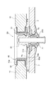
図1は、本発明の一実施形態によるマット固定具で自動車用フロアマットをフロアに固定した状態を示す概略断面図である。図において、マット固定具、特に、自動車用フロアマット固定具20は、自動車のフロア7に固定された雄固定具30と、フロアマット10に形成された開口11に固定された雌固定具40とを備えており、雄固定具30及び雌固定具40によってフロアマット10がフロア7に固定されている。
【0019】
図2は、雄固定具30を示す概略断面図であり、雄固定具をフロア7に固定するベース部材31に装着された状態を示している。雄固定具30は、中心軸32から円周方向に突出した突出部33が形成されたヘッド部34と、ヘッド部34の下方に延びる脚部35とを備えており、これらのヘッド部34及び脚部35の間には、突出部33との間に首部36を形成する鍔部37が設けられている。
【0020】
ベース部材31は、雄固定具30が挿入されるベース本体31aと、フロア7の端部と締結する締結部31b(図1参照)とから構成されている。図3は、ベース部材31に上方から雄固定具30が途中まで挿入された仮止め状態を示している。なお、ベース部材31がフロア7から突出して、フロアマット10との間に隙間を形成せず、フロア7とフロアマット10との一体感があるように、ベース部材31におけるベース本体31aの上面31eが、フロア7の上面7bと面一であるのが好ましい。この場合、図1に示すよりもベース本体31aの上面31eの傾斜を小さくするのが好ましい。
【0021】
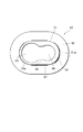
図4〜6は、雌固定具40の上部固定具50を示すそれぞれ概略側断面図、裏面図及び平面図である。これらの図において、上部固定具50は、第1の胴部51と、この第1の胴部51の上端に形成される第1の外向きフランジ52とを備えている。第1の胴部51には、雄固定具30のヘッド部34が挿入される第1の開口53が形成されている。ヘッド部34は、第1の開口53の外端面53aに鍔部37が当接するまで第1の開口53に挿入されるので、第1の開口53の内径は、突出部33の外径とほぼ等しいか、又はやや大きい。ここで、第1の開口53が大きいと、フロア7におけるベース部材31の設置位置に誤差があっても確実に固定できるため、デザイン上、許容できる範囲内で、第1の開口53が大きいのが好ましい。特に、フロア7の2カ所以上にベース部材31を設置する場合、第1の開口53が大きいのがより好ましい。
【0022】
第1の開口53に隣接して、雄固定具30の首部36に嵌り合う凸縁部54が形成された第2の開口55が設けられている。また、第1の開口53と第2の開口55との間に、第2の開口55における凸縁部54の内径よりやや小さい幅の凸縁部56を有する連結部57を備えても良い。この連結部57により、第2の開口55内に収容された雄固定具30が第1の開口53に戻るのを確実に防止することができる。なお、第1の胴部51の外壁には、上部固定具50と下部固定具60とが嵌合された際に、上部固定具50と下部固定具60との緩みや抜け落ちを防止する抜け止め51aが形成されている。この抜け止め51aは、多数の線状凹凸や、爪部材など種々の部材により作製することができる。
【0023】
図7及び8は、雌固定具40の下部固定具60を示すそれぞれ概略平面図及び側面図である。これらの図において、下部固定具60は、上部固定具50の第1の胴部51に嵌合される第2の胴部61と、この第2の胴部61の下端に形成される第2の外向きフランジ62とを備えている。第2の胴部61の内壁には、第1の胴部51に形成された抜け止め51aと噛み合う抜け止め61aが形成されている。
【0024】
次に、自動車用フロアマットの固定方法について説明する。まず、図1に示すように、フロア7に形成された開口7aに締結部31bが設けられたベース部材31を挿入し、フロア7の端面を締結部31bで挟み込むことにより、ベース部材31をフロア7に固定する。次に、図3に示すように、ベース部材31の開口31dに雄固定具30を挿入し、さらに図2に示すように、鍔部37がベース本体31aに当接するまで雄固定具30を押し込む。このとき、ベース本体31aの開口31dに形成された凸部31cと、雄固定具30の脚部35に形成された凹部35aとが嵌り合い、雄固定具30がベース部材31に固定される。
【0025】
フロアマット10には、予め形成されている開口11に、雌固定具40の上部固定具50及び下部固定具60をそれぞれ上下から挿入し、第1の胴部51と第2の胴部61とを嵌め込む。このとき、第2の外向きフランジ62の下面と第1の胴部51の外端面53aとは、フロア7との間に隙間ができないように、面一となることが望ましい。こうして、フロアマット10の開口側端部10aが第1及び第2の外向きフランジ52及び62により挟持され、フロアマット10に雌固定具40が固定される。
【0026】
マット固定具20によるフロアマット10のフロア7への固定は、図9及び10に示すように行われる。なお、これらの図では、簡略化のために雄固定具30及び雌固定具40の上部固定具50だけを概略的に示す。まず、図9の矢印Aに示すように、フロア7に固定された雄固定具30に対し、フロアマット10に固定された雌固定具40の第1の開口53を被せるようにして挿入する。このとき、第1の開口53はヘッド部34の突出部33の外径に比べて大きいので、フロアマット10を雄固定具30の上方から被せるだけで、雄固定具30を第1の開口53に容易に挿入することができる。
【0027】
続いて、図10の矢印Bに示すように、フロアマット10をヘッド部34が第2の開口55に収容されるように摺動させる。すると、ヘッド部34の突出部33及び鍔部37により形成される首部36が凸縁部54に嵌り合うので、雄固定具30が雌固定具40から抜けず、フロアマット10をフロア7に固定することができる。このように、雄固定具30に雌固定具40を被せてスライドさせるだけで、フロアマット10をフロア7に固定することができるので、フロアマット10の装着作業性に優れている。
【0028】
また、雄固定具30の突出部33及び鍔部37により形成される首部36と、雌固定具40の凸縁部54との嵌り合いにより、雄固定具30と雌固定具40とは十分な強度で固定され、フロアマット10が浮き上がって外れることがない。さらに、第2の開口55における凸縁部54の内径よりやや小さい幅の凸縁部56を有する連結部57を備えることにより、雄固定具30が第1の開口53に戻るのを防止できるので、フロアマット10を一層確実に固定することができる。
【0029】
上述した実施形態においては、自動車のフロア7にベース部材31を1個設けてフロアマット10を固定する場合について説明したが、フロア7の2カ所以上にそれぞれベース部材31を設け、2個以上の雌固定具40を固定したフロアマット10を雄固定具30で固定しても良く、このようにすれば、フロアマット10をより確実に固定することができる。この場合であっても、フロアへの装着作業性に優れている。
【0030】
また、図6に示すように、上部固定具50の上面は開放されているので、上方から雄固定具30の位置を確認し易いが、異物が第1の開口53内に入るのを防止し、又は意匠性を向上させるために、図11に示すように、蓋部材58を設けることもできる。蓋部材58を設ける場合には、第1の開口53及び第2の開口55の全体を覆うように設けることもできるが、装着状態を確認できるように、第2の開口55の一部又は全部は覆われていないように蓋部材58を設けるのが好ましく、第2の開口55の全部が覆われていないように蓋部材58を設けるのがより好ましい。
【0031】
また、雌固定具40の下部固定具60の第2の胴部61よりも大きな開口を有するフロアマット10に対して、上部固定具50と下部固定具60とを嵌め合わせて雌固定具40をフロアマット10に固定するのが好ましい。このように雌固定具40を固定することによって、フロア7におけるベース部材31の設置位置に誤差があっても、雌固定具40がフロアマット10の開口11内で適宜移動し、前記誤差を吸収して、フロアマット10を確実に固定することができる。
【0032】
これは、特にフロアの2カ所以上にベース部材31を設置する場合に有効である。なお、この場合、上部固定具50の第1の外向きフランジ52及び下部固定具60の第2の外向きフランジ62の大きさを適宜調節することにより、フロアマット10の開口側端部10aの露出を防ぎ、フロアマット10の構成繊維の脱落や、意匠性の低下を抑えるのが好ましい。
【0033】
また、雄固定具30及び/又は雌固定具40は種々の合成樹脂等から作製されるが、この合成樹脂に顔料を配合するなどして、フロアマット10表面の繊維層の色とコーディネートすることや、各種形状にデザインすることにより、フロアマット10とマット固定具20との一体感を増し、意匠性を向上させることができる。
【0034】
さらに、雄固定具30及び/又は雌固定具40は種々の合成樹脂等から作製することができ、フロアマット10と共に回収、廃棄することができ、リサイクル性に優れている。或いは、雌固定具40は上部固定具50と下部固定具60とを脱着することも可能であり、これらの固定具とフロアマット10とを別々に回収してリサイクルすることもできる。
【0035】
また、図12に示すように、ヘッド部70の中心軸71と脚部35の中心軸72とが一致しておらず、偏心していても良い。このような場合であっても、両軸のぶれと第1の開口53の内径とを調節することにより、フロアマット10を雄固定具30の上方から被せるだけで、雄固定具30を第1の開口53に容易に挿入することができる。
【0036】
フロアマット10における雌固定具40の設置位置は、運転操作の邪魔にならず、固定性に優れているように、ペダル側とは反対側の位置(座席シート付近)であるのが好ましい。また、雌固定具40の第2の開口55が座席シート側に位置しているのが好ましい。このように位置していることによって、第2の開口55に雄固定具30が位置するように、運転操作中の踏力(自動車の進行方向)が作用し、運転操作中にフロアマット10が外れにくいためである。
【0037】
【発明の効果】
以上説明したように、請求項1の発明によれば、雌固定具を装着したマットを雄固定具の上方から被せるだけで、雄固定具のヘッド部を雌固定具の第1の開口に挿入することができ、その後単にスライドさせるだけで雄固定具のヘッド部を雌固定具の第2の開口へ移動させて固定できるので、装着作業性に優れているという効果を奏する。また、雄固定具及び雌固定具によりマットが浮き上がって外れることがないという効果を奏する。
【0038】
請求項2の発明によれば、雌固定具の上部固定具における第1の開口及び第2の開口の間に第2の開口における凸縁部の内径よりやや小さい幅の凸縁部を有する連結部を備えるので、雄固定具が第1の開口に戻るのを防止し、マットの固定をより確実にすることができるという効果を奏する。
【0039】
請求項3の発明によれば、自動車用フロアマットに形成された少なくとも1カ所の開口に雌固定具が固定されているので、自動車のフロアへの装着作業性に優れ、また、フロアマットが浮き上がって外れることがないという効果を奏する。さらに、フロアマットを2カ所以上でフロアに固定する場合であっても、フロアへの装着作業性に優れ、また、フロアマットをより確実にフロアに固定することができるという効果を奏する。
【0040】
請求項4の発明によれば、雄固定具が自動車のフロアに形成された開口に固定され、雌固定具における第2の開口に、前記雄固定具が固定されているので、装着作業性に優れ、雄固定具及び雌固定具によりフロアマットがフロアから浮き上がって外れることがないという効果を奏する。
【図面の簡単な説明】
【図1】本発明の一実施形態によるマット固定具で自動車用フロアマットをフロアに固定した状態を示す概略断面図である。
【図2】マット固定具の雄固定具を示す概略断面図である。
【図3】ベース部材に上方から雄固定具が途中まで挿入された状態を示す概略断面図である。
【図4】雌固定具の上部固定具を示す概略側断面図である。
【図5】雌固定具の上部固定具を示す裏面図である。
【図6】雌固定具の上部固定具を示す平面図である。
【図7】雌固定具の下部固定具を示す平面図である。
【図8】雌固定具の下部固定具を示す側面図である。
【図9】雌固定具の上部固定具に雄固定具が挿入される状態を示す説明図である。
【図10】雌固定具の上部固定具に挿入された雄固定具が第1の開口から第2の開口に摺動する状態を示す説明図である。
【図11】本発明の他の実施の形態による雌固定具の上部固定具を示す平面図である。
【図12】本発明のさらに他の実施の形態による雄固定具を示す概略断面図である。
【図13】従来の自動車用フロアマットの固定治具を示す概略斜視図である。
【図14】従来の他のマット固定具を示す概略断面図である。
【符号の説明】
1…固定治具、2…上部クリップ、2a…先端部、3…下部クリップ、3a…先端部、4…固定部、5…固定具、6…脚部、7…フロア、7a…開口、7b…上面、8…リング、9…フック部、10…フロアマット、10a…開口側端部、11…開口、12…リング、13…軸、20…固定具、30…雄固定具、31…ベース部材、31a…ベース本体、31b…締結部、31c…凸部、31d…開口、31e…上面、32…中心軸、33…突出部、34…ヘッド部、35…脚部、35a…凹部、36…首部、37…鍔部、40…雌固定具、50…上部固定具、51…第1の胴部、51a…抜け止め、52…第1の外向きフランジ、53…第1の開口、53a…外端面、54…凸縁部、55…第2の開口、56…凸縁部、57…連結部、58…蓋部材、60…下部固定具、61…第2の胴部、61a…抜け止め、62…第2の外向きフランジ、70…ヘッド部、71…中心軸、72…中心軸、A,B…矢印。[0001]
TECHNICAL FIELD OF THE INVENTION
The present invention relates to a mat fixing device, an automobile floor mat and a fixing structure thereof, and more particularly to a mat fixing device which does not come off and is excellent in mounting workability, an automobile floor mat and a fixing structure thereof.
[0002]
[Prior art]
2. Description of the Related Art Conventionally, floor mats have been laid in automobiles in order to prevent soil, sand, mud, gravel or the like adhering to shoes or the like from adhering to the floor and soiling the floor. This floor mat is fixed to the floor by various methods in order to exhibit the above function.
[0003]
FIG. 13 is a schematic perspective view showing a conventional jig for fixing a floor mat for an automobile. (For example, see Patent Document 1).
[0004]
In the drawing, a fixing jig 1 includes an
[0005]
As another mat fixing method, there is a method using a fixing tool 5 as shown in FIG. That is, the leg 6 of the fixture 5 is inserted into the
[0006]
According to this method, the movement of the
[0007]
[Patent Document 1]
Japanese Utility Model Publication No. 5-29943 (
[0008]
[Problems to be solved by the invention]
However, even if the
[0009]
The present invention has been made in order to solve such a conventional problem, and provides a mat fixing device, a floor mat for automobiles, and a fixing structure for the floor mat which does not come off due to the floor mat being lifted up and which is excellent in workability of mounting. The purpose is to do.
[0010]
[Means for Solving the Problems]
The invention according to claim 1 of the present invention is a mat fixing device including a male fixing device and a female fixing device, wherein the male fixing device has a head portion having a protruding portion in a circumferential direction, and a lower portion below the head portion. An adjoining leg, and a flange provided between the head and the leg and forming a neck between the protrusion and the protrusion, the female fixing device includes a first part into which the head is inserted. An opening, a first body portion provided adjacent to the first opening and having a second opening having a protruding edge portion fitted to the neck portion, and formed at an upper end of the first body portion. An upper fixing device having a first outward flange to be fitted, a second trunk portion fitted to the first trunk portion, and a second outward flange formed at a lower end of the second trunk portion. And a lower fixing device.
[0011]
The invention according to
[0012]
The invention according to
[0013]
The invention according to claim 4 is a fixing structure of a floor mat for an automobile, wherein the male fixing tool according to claim 1 is fixed to an opening formed in a floor of the automobile, and the female fixing tool according to
[0014]
According to the invention of claim 1, the head portion of the male fixing tool can be inserted into the first opening of the female fixing tool simply by covering the mat on which the female fixing tool is mounted from above the male fixing tool. Since the head portion of the male fixture can be moved to and fixed to the second opening of the female fixture by simply sliding, the mounting workability is excellent. Further, the mat is not lifted off by the male fixture and the female fixture.
[0015]
According to the invention of
[0016]
According to the third aspect of the present invention, since the female fixture is fixed to at least one opening formed in the floor mat for an automobile, the workability for mounting on the floor of the automobile is excellent, and the floor mat rises. Never come off. Further, even when the floor mat is fixed to the floor at two or more locations, the workability for mounting on the floor is excellent, and the floor mat can be more securely fixed to the floor.
[0017]
According to the invention of claim 4, since the male fixing tool is fixed to the opening formed on the floor of the automobile, and the male fixing tool is fixed to the second opening of the female fixing tool, the mounting workability is improved. Excellent, the floor mat is not lifted off the floor by the male fixture and the female fixture.
[0018]
BEST MODE FOR CARRYING OUT THE INVENTION
FIG. 1 is a schematic sectional view showing a state in which an automobile floor mat is fixed to a floor with a mat fixture according to an embodiment of the present invention. In the figure, a mat fixing device, in particular, an automobile floor
[0019]
FIG. 2 is a schematic cross-sectional view showing the
[0020]
The
[0021]
4 to 6 are a schematic side sectional view, a rear view, and a plan view, respectively, showing the
[0022]
Adjacent to the
[0023]
FIGS. 7 and 8 are a schematic plan view and a side view, respectively, showing the
[0024]
Next, a method of fixing the floor mat for an automobile will be described. First, as shown in FIG. 1, a
[0025]
In the
[0026]
The fixing of the
[0027]
Subsequently, as shown by an arrow B in FIG. 10, the
[0028]
In addition, the fitting of the
[0029]
In the above-described embodiment, the case where one
[0030]
Further, as shown in FIG. 6, since the upper surface of the
[0031]
The
[0032]
This is particularly effective when the
[0033]
The
[0034]
Furthermore, the
[0035]
In addition, as shown in FIG. 12, the
[0036]
The installation position of the
[0037]
【The invention's effect】
As described above, according to the first aspect of the present invention, the head portion of the male fixing device is inserted into the first opening of the female fixing device simply by covering the mat on which the female fixing device is mounted from above the male fixing device. After that, the head portion of the male fixture can be moved to the second opening of the female fixture and fixed by simply sliding thereafter, so that there is an effect that the mounting workability is excellent. In addition, there is an effect that the mat is not lifted off by the male fixture and the female fixture.
[0038]
According to the invention of
[0039]
According to the third aspect of the present invention, since the female fixture is fixed to at least one opening formed in the floor mat for an automobile, the workability for mounting on the floor of the automobile is excellent, and the floor mat is raised. This has the effect of not falling off. Further, even when the floor mat is fixed to the floor at two or more locations, the workability of mounting the floor mat is excellent, and the floor mat can be more securely fixed to the floor.
[0040]
According to the invention of claim 4, since the male fixing tool is fixed to the opening formed on the floor of the automobile, and the male fixing tool is fixed to the second opening of the female fixing tool, the mounting workability is improved. Excellent, the male mat and the female fixture have the effect of preventing the floor mat from being lifted off the floor.
[Brief description of the drawings]
FIG. 1 is a schematic sectional view showing a state in which an automobile floor mat is fixed to a floor with a mat fixture according to an embodiment of the present invention.
FIG. 2 is a schematic sectional view showing a male fixture of the mat fixture.
FIG. 3 is a schematic cross-sectional view showing a state in which a male fixture is partially inserted into the base member from above.
FIG. 4 is a schematic side sectional view showing an upper fixing tool of the female fixing tool.
FIG. 5 is a rear view showing the upper fixing tool of the female fixing tool.
FIG. 6 is a plan view showing an upper fixing device of the female fixing device.
FIG. 7 is a plan view showing a lower fixture of the female fixture.
FIG. 8 is a side view showing a lower fixture of the female fixture.
FIG. 9 is an explanatory view showing a state where the male fixing tool is inserted into the upper fixing tool of the female fixing tool.
FIG. 10 is an explanatory view showing a state in which the male fixing tool inserted into the upper fixing tool of the female fixing tool slides from the first opening to the second opening.
FIG. 11 is a plan view showing an upper fixing device of a female fixing device according to another embodiment of the present invention.
FIG. 12 is a schematic sectional view showing a male fixture according to still another embodiment of the present invention.
FIG. 13 is a schematic perspective view showing a conventional jig for fixing a floor mat for an automobile.
FIG. 14 is a schematic sectional view showing another conventional mat fixture.
[Explanation of symbols]
DESCRIPTION OF SYMBOLS 1 ... Fixing jig, 2 ... Upper clip, 2a ... Tip, 3 ... Lower clip, 3a ... Tip, 4 ... Fixing part, 5 ... Fixing tool, 6 ... Leg, 7 ... Floor, 7a ... Opening, 7b ... Top, 8 ... Ring, 9 ... Hook, 10 ... Floor mat, 10a ... Open end, 11 ... Opening, 12 ... Ring, 13 ... Shaft, 20 ... Fixing tool, 30 ... Male fixing tool, 31 ... Base Member, 31a: Base body, 31b: Fastening portion, 31c: Convex portion, 31d: Opening, 31e: Upper surface, 32: Central axis, 33: Projecting portion, 34: Head portion, 35: Leg portion, 35a: Depressed portion, 36 ... Neck part, 37 ... Flange part, 40 ... Female fixing part, 50 ... Top fixing part, 51 ... First body part, 51a ... Retaining, 52 ... First outward flange, 53 ... First opening, 53a ... Outer end face, 54... Convex edge, 55... Second opening, 56. Lid member, 60 lower fixture, 61 second body, 61a retaining, 62 second outward flange, 70 head part, 71 central axis, 72 central axis, A, B ... Arrow.
Claims (4)
前記雄固定具は、
周方向に突出部を有するヘッド部と、
前記ヘッド部の下方に隣接する脚部と、
前記ヘッド部及び脚部の間に設けられ、前記突出部との間に首部を形成する鍔部とを備え、
前記雌固定具は、
前記ヘッド部が挿入される第1の開口、前記第1の開口に隣接して設けられ、前記首部に嵌合する凸縁部を有する第2の開口が形成された第1の胴部、及び前記第1の胴部上端に形成される第1の外向きフランジを備える上部固定具と、
前記第1の胴部に嵌合される第2の胴部、前記第2の胴部下端に形成される第2の外向きフランジを備える下部固定具と
を備えることを特徴とする、マット固定具。A mat fixture comprising a male fixture and a female fixture,
The male fastener is
A head portion having a circumferentially projecting portion,
Legs adjacent below the head,
A flange portion provided between the head portion and the leg portion and forming a neck portion with the protruding portion;
The female fixture,
A first opening into which the head portion is inserted, a first body portion provided adjacent to the first opening and having a second opening having a convex edge portion fitted to the neck portion; An upper fixture having a first outward flange formed at an upper end of the first trunk;
A mat fixing device comprising: a second body portion fitted to the first body portion; and a lower fixing device having a second outward flange formed at a lower end of the second body portion. Utensils.
前記フロアマットに形成された少なくとも1カ所の開口に、請求項1に記載の雌固定具の上部固定具及び下部固定具がそれぞれ挿入され、前記上部固定具及び下部固定具のそれぞれ第1の胴部及び第2の胴部が互いに嵌合することにより、前記雌固定具が前記少なくとも1カ所の開口に固定されていることを特徴とする、自動車用フロアマット。A floor mat for an automobile,
The upper fixing tool and the lower fixing tool of the female fixing tool according to claim 1 are inserted into at least one opening formed in the floor mat, respectively, and the first body of the upper fixing tool and the lower fixing tool respectively. An automobile floor mat, wherein the female fixing device is fixed to the at least one opening by fitting the portion and the second body portion with each other.
請求項1に記載の雄固定具が自動車のフロアに形成された開口に固定され、請求項3に記載の雌固定具における第2の開口に、前記雄固定具が固定されていることを特徴とする、自動車用フロアマットの固定構造。A fixed structure for an automobile floor mat,
The male fixing device according to claim 1 is fixed to an opening formed in a floor of an automobile, and the male fixing device is fixed to a second opening of the female fixing device according to claim 3. The fixing structure of floor mats for automobiles.
Priority Applications (1)
| Application Number | Priority Date | Filing Date | Title |
|---|---|---|---|
| JP2003062330A JP2004268731A (en) | 2003-03-07 | 2003-03-07 | Mat anchor, floor mat and its fixing structure for vehicle |
Applications Claiming Priority (1)
| Application Number | Priority Date | Filing Date | Title |
|---|---|---|---|
| JP2003062330A JP2004268731A (en) | 2003-03-07 | 2003-03-07 | Mat anchor, floor mat and its fixing structure for vehicle |
Publications (1)
| Publication Number | Publication Date |
|---|---|
| JP2004268731A true JP2004268731A (en) | 2004-09-30 |
Family
ID=33124281
Family Applications (1)
| Application Number | Title | Priority Date | Filing Date |
|---|---|---|---|
| JP2003062330A Pending JP2004268731A (en) | 2003-03-07 | 2003-03-07 | Mat anchor, floor mat and its fixing structure for vehicle |
Country Status (1)
| Country | Link |
|---|---|
| JP (1) | JP2004268731A (en) |
Cited By (6)
| Publication number | Priority date | Publication date | Assignee | Title |
|---|---|---|---|---|
| EP2223637A1 (en) | 2009-02-25 | 2010-09-01 | Newfrey LLC | Fastening assembly for securing a floor mat to a carpet |
| JP2011079446A (en) * | 2009-10-07 | 2011-04-21 | Honda Access Corp | Floor mat and method for laying the same |
| WO2012039058A1 (en) * | 2010-09-24 | 2012-03-29 | Ykk株式会社 | Fixtures, locking system, and method for securing object |
| US20120183745A1 (en) * | 2008-09-02 | 2012-07-19 | Stanesic John M | Vehicle Floor Tray |
| JP2020097306A (en) * | 2018-12-18 | 2020-06-25 | トヨタ車体株式会社 | Mounting structure of vehicular interior component |
| WO2023112043A1 (en) * | 2021-12-13 | 2023-06-22 | Saurabh Kapoor | Anti-skid clip |
-
2003
- 2003-03-07 JP JP2003062330A patent/JP2004268731A/en active Pending
Cited By (12)
| Publication number | Priority date | Publication date | Assignee | Title |
|---|---|---|---|---|
| US20120183745A1 (en) * | 2008-09-02 | 2012-07-19 | Stanesic John M | Vehicle Floor Tray |
| EP2223637A1 (en) | 2009-02-25 | 2010-09-01 | Newfrey LLC | Fastening assembly for securing a floor mat to a carpet |
| JP2010195179A (en) * | 2009-02-25 | 2010-09-09 | Nippon Pop Rivets & Fasteners Ltd | Fixing device for fixing floor mat to carpet |
| US8375514B2 (en) | 2009-02-25 | 2013-02-19 | Newfrey Llc | Fastening assembly for securing floor mat to carpet |
| JP2011079446A (en) * | 2009-10-07 | 2011-04-21 | Honda Access Corp | Floor mat and method for laying the same |
| WO2012039058A1 (en) * | 2010-09-24 | 2012-03-29 | Ykk株式会社 | Fixtures, locking system, and method for securing object |
| CN103052812A (en) * | 2010-09-24 | 2013-04-17 | Ykk株式会社 | Fixtures, locking system, and method for securing object |
| JP5558576B2 (en) * | 2010-09-24 | 2014-07-23 | Ykk株式会社 | Fixing tool, locking system, and fixing method of fixing object |
| CN103052812B (en) * | 2010-09-24 | 2015-07-29 | Ykk株式会社 | The fixation method of fixed block, locking system and fixed object thing |
| JP2020097306A (en) * | 2018-12-18 | 2020-06-25 | トヨタ車体株式会社 | Mounting structure of vehicular interior component |
| JP7159846B2 (en) | 2018-12-18 | 2022-10-25 | トヨタ車体株式会社 | Mounting structure for vehicle interior parts |
| WO2023112043A1 (en) * | 2021-12-13 | 2023-06-22 | Saurabh Kapoor | Anti-skid clip |
Similar Documents
| Publication | Publication Date | Title |
|---|---|---|
| JP2004268731A (en) | Mat anchor, floor mat and its fixing structure for vehicle | |
| JP4098518B2 (en) | Floor covering for powered vehicles | |
| KR101357393B1 (en) | Fixing device of auxiliary mat automobile | |
| CN107264369B (en) | Fixing device for mounting foot pad | |
| KR20100061173A (en) | Hook for Automobile Sub-Mat | |
| KR101592715B1 (en) | Car Mat fixate device | |
| KR101477924B1 (en) | Fixing device of auxiliary mat automobile | |
| JP3684255B2 (en) | Parts mounting structure | |
| JPH11230134A (en) | Hook fastener | |
| JP2006168679A (en) | Roof structure of vehicle | |
| JP4181739B2 (en) | Floor mat fixing reinforcement | |
| JP5952368B2 (en) | Floor mat fixing structure | |
| KR100559049B1 (en) | Assist mat hook for automobile | |
| JPH0237050Y2 (en) | ||
| FR2803866B1 (en) | LOCK ASSEMBLY, PARTICULARLY FOR FIXING A SEAT ON A MOTOR VEHICLE FLOOR | |
| JP2021020623A (en) | Rail end cap | |
| JP3651292B2 (en) | Floor panel seat mounting structure | |
| JPS637103Y2 (en) | ||
| JPH0554809U (en) | clip | |
| JPH0624278Y2 (en) | Locking member for floor mat | |
| JP2005246982A (en) | Assist grip and its mounting structure | |
| JPS61215133A (en) | Floor mat for automobile provided with setting part and manufacture thereof | |
| KR101734672B1 (en) | Fastener of auxiliary mat for vehicle and operating method thereof | |
| JPS6116168Y2 (en) | ||
| JPH02126935U (en) |