JP2004264635A - camera - Google Patents
camera Download PDFInfo
- Publication number
- JP2004264635A JP2004264635A JP2003055348A JP2003055348A JP2004264635A JP 2004264635 A JP2004264635 A JP 2004264635A JP 2003055348 A JP2003055348 A JP 2003055348A JP 2003055348 A JP2003055348 A JP 2003055348A JP 2004264635 A JP2004264635 A JP 2004264635A
- Authority
- JP
- Japan
- Prior art keywords
- focus position
- evaluation value
- focus
- determined
- predetermined positions
- Prior art date
- Legal status (The legal status is an assumption and is not a legal conclusion. Google has not performed a legal analysis and makes no representation as to the accuracy of the status listed.)
- Pending
Links
Images
Landscapes
- Focusing (AREA)
- Indication In Cameras, And Counting Of Exposures (AREA)
- Automatic Focus Adjustment (AREA)
- Studio Devices (AREA)
Abstract
【課題】オートフォーカス機能を有するカメラにおいて、より確実なピント合わせを可能にする。
【解決手段】デジタルカメラ100において、評価値算出手段が至近撮像位置から最遠撮像位置までの間の複数の所定位置における被写体光像の合焦状態を示す評価値を算出し、算出された複数の所定位置の評価値に基づいて、合焦位置決定手段が合焦位置を決定するようにオートフォーカス機能が動作する。そして、表示手段が、その算出された複数の所定位置の評価値と、決定された合焦位置とを対応させて表示する。さらに、表示された評価値と合焦位置を確認しつつ、合焦位置調整手段が、合焦位置決定手段により決定された合焦位置とをマニュアル操作による調整を行い、より確実にピント合わせする構成にした。
【選択図】 図1An object of the present invention is to enable more accurate focusing in a camera having an autofocus function.
In a digital camera, an evaluation value calculation unit calculates an evaluation value indicating an in-focus state of a subject light image at a plurality of predetermined positions from a closest imaging position to a farthest imaging position. The auto focus function operates so that the focus position determining means determines the focus position based on the evaluation value of the predetermined position. Then, the display means displays the calculated evaluation values of the plurality of predetermined positions in correspondence with the determined in-focus positions. Further, while confirming the displayed evaluation value and the in-focus position, the in-focus position adjusting means adjusts the in-focus position determined by the in-focus position determining means by manual operation to more reliably focus. Was configured.
[Selection diagram] Fig. 1
Description
【0001】
【発明の属する技術分野】
本発明は、カメラに係り、詳細にはオートフォーカス調整及びマニュアル操作でフォーカス調整を行うことが可能なカメラに関する。
【0002】
【従来の技術】
従来より、自動で焦点調整(合焦)を行うオートフォーカスカメラが知られている。オートフォーカスカメラは、ほとんどの被写体に自動でピント合わせを行うが、なかにはオートフォーカスではピント合わせが難しい被写体もあり、マニュアル操作でピント合わせを行った方が確実に行えるものもある。
そのようなマニュアル操作でピント合わせを行う際に、ピントの合い具合(合焦状態)を確認することができるカメラが知られている(例えば、特許文献1参照。)。
【0003】
【特許文献1】
特開平6−113184号公報
【0004】
【発明が解決しようとする課題】
しかしながら、上記特許文献1の場合、オートフォーカスカメラの使用に慣れた者にとっては、マニュアル操作でピントをうまく合わせること自体が難しい場合があり、マニュアル操作によりピントが合った状態をカメラの使用者が確認することも困難である場合があった。
【0005】
本発明の課題は、オートフォーカス機能を有するカメラにおいて、より確実にピント合わせを行うことができるカメラを提供することである。
【0006】
【課題を解決するための手段】
以上の課題を解決するため、請求項1記載の発明は、
至近撮像位置から最遠撮像位置までの間の複数の所定位置に対応するレンズ位置での被写体光像の合焦状態を示す評価値を算出する評価値算出手段と、
前記評価値算出手段により算出された前記複数の所定位置の評価値に基づいて、合焦位置を決定する合焦位置決定手段と、
前記評価値算出手段により算出された前記複数の所定位置の評価値と、前記合焦位置決定手段により決定された合焦位置とを対応させて表示する表示手段と、
を備えることを特徴とする。
【0007】
請求項1記載の発明によれば、評価値算出手段が至近撮像位置から最遠撮像位置までの間の複数の所定位置に対応するレンズ位置での被写体光像の合焦状態を示す評価値を算出し、算出された複数の所定位置の評価値に基づいて、合焦位置決定手段が合焦位置を決定する。そして、表示手段が、その算出された複数の所定位置の評価値と、決定された合焦位置とを対応させて表示する。
よって、カメラは、オートフォーカス機能により決定した合焦位置を、合焦位置を決定する基準とした評価値とともに表示することができるので、カメラの使用者は、その合焦位置についての確認、例えば、どのように分布する評価値から合焦位置に対応する評価値が選択、決定されたかという確認や、決定された合焦位置に対応する評価値とそれ以外の評価値との差の程度、つまり、合焦位置に対応する評価値と類似する評価値の有無の確認などを行うことができる。従って、オートフォーカス機能を利用し、被写体を撮像する場合であっても、合焦位置の適正程度や、ピントの合い具合を確認することができる。
そして、その表示をピント合わせの指標とすることで、オートフォーカスをし直す等により確実に合焦位置を調整し、より確実なピント合わせを行うことができる。
【0008】
なお、複数の所定位置とは、例えば、至近撮像位置としてのカメラから0mの位置から、最遠撮像位置としてのカメラから∞(無限大)の位置までの間において、任意の間隔(例えば、1m毎、或いはカメラのレンズがパルス駆動制御により移動制御される場合は、所定のパルス数(例えば、10パルス)毎)に設定された複数の基準位置のことである。
【0009】
請求項2記載の発明は、請求項1に記載のカメラにおいて、
前記合焦位置決定手段により決定された合焦位置を、マニュアル操作により調整する合焦位置調整手段と、
前記合焦位置調整手段により調整された合焦位置に応じて、前記表示手段によって表示される合焦位置の変更を行う表示変更手段と、
を備えることを特徴とする。
【0010】
請求項2記載の発明によれば、請求項1に記載の発明と同様の作用を奏するとともに、合焦位置調整手段が合焦位置決定手段により決定された合焦位置をマニュアル操作による調整を行い、調整された合焦位置に応じて、表示変更手段が表示手段によって表示される合焦位置の変更を行う。
つまり、カメラが、オートフォーカス機能により決定した合焦位置を、マニュアル操作により調整することができるので、オートフォーカス機能により決定した合焦位置を微調整し、所望する合焦位置に変更することができる。特に、合焦位置を決定する基準とした評価値とともに合焦位置が表示されているので、その評価値を参考にすることで容易に合焦位置の調整、変更を行うことができる。
また、調整、変更された合焦位置に応じて、その表示も変更されるので、変更履歴を確認しつつ、合焦位置の調整、変更を行うことができる。
よって、より確実に合焦位置を調整し、より確実なピント合わせを行うことができる。
【0011】
請求項3記載の発明は、
至近撮像位置から最遠撮像位置までの間の複数の所定位置に対応するレンズ位置での被写体光像の合焦状態を示す評価値を算出する評価値算出手段と、
前記評価値算出手段により算出された前記複数の所定位置の評価値に基づいて、合焦位置を決定する合焦位置決定手段と、
前記評価値算出手段により算出された前記複数の所定位置の評価値が、予め設定された合焦位置確定条件を満たすか否かを判断する判断手段と、
前記判断手段によって、前記評価値算出手段により算出された前記複数の所定位置の評価値が、予め設定された合焦位置確定条件を満たさないと判断された場合に、前記評価値算出手段により算出された前記複数の所定位置の評価値と、前記合焦位置決定手段により決定された合焦位置とを対応させて表示する表示手段と、
を備えることを特徴とする。
【0012】
請求項3記載の発明によれば、評価値算出手段が至近撮像位置から最遠撮像位置までの間の複数の所定位置に対応するレンズ位置での被写体光像の合焦状態を示す評価値を算出し、算出された複数の所定位置の評価値に基づいて、合焦位置決定手段が合焦位置を決定する。そして、判断手段が、その算出された評価値が予め設定された合焦位置確定条件を満たすか否かを判断し、所定の合焦位置確定条件を満たさないと判断した場合に、表示手段が、その算出された複数の所定位置の評価値と、決定された合焦位置とを対応させて表示する。
つまり、カメラは、オートフォーカス機能により決定した合焦位置に関して、その合焦位置を決定する基準とした評価値が予め設定された合焦位置確定条件を満たすか否かを判断することで、適正な合焦位置か否かの判断を行う。そして、その評価値が、所定の合焦位置確定条件を満たさないと判断した場合に、表示手段が、その算出された複数の所定位置の評価値と、決定された合焦位置とを対応させて表示するので、カメラの使用者は、決定された合焦位置が適正か否かの確認、例えば、決定された合焦位置に対応する評価値と類似する評価値の有無の確認などを行うことができる。
そして、その表示をピント合わせの指標とすることで、より確実に合焦位置を調整し、より確実なピント合わせを行うことができる。
【0013】
なお、複数の所定位置とは、例えば、至近撮像位置としてのカメラから0mの位置から、最遠撮像位置としてのカメラから∞(無限大)の位置までの間において、等間隔(例えば、1m毎)に設定された複数の基準位置のことである。
【0014】
請求項4記載の発明は、請求項3に記載のカメラにおいて、
前記合焦位置決定手段により決定された合焦位置を、マニュアル操作により調整する合焦位置調整手段と、
前記合焦位置調整手段により調整された合焦位置に応じて、前記表示手段によって表示される合焦位置の変更を行う表示変更手段と、
を備えることを特徴とする。
【0015】
請求項4記載の発明によれば、請求項3に記載の発明と同様の作用を奏するとともに、合焦位置調整手段が合焦位置決定手段により決定された合焦位置をマニュアル操作による調整を行い、調整された合焦位置に応じて、表示変更手段が表示手段によって表示される合焦位置の変更を行う。
つまり、カメラが、オートフォーカス機能により決定した合焦位置を、マニュアル操作により調整することができるので、オートフォーカス機能により決定した合焦位置を微調整し、所望する合焦位置に変更することができる。また、合焦位置を決定する基準とした評価値とともに合焦位置が表示されているので、その評価値を参考にすることで容易に合焦位置の調整、変更を行うことができる。また、調整、変更された合焦位置に応じて、その表示も変更されるので、変更履歴を確認しつつ、合焦位置の調整、変更を行うことができる。
特に、その合焦位置を決定する基準とした評価値が、所定の合焦位置確定条件を満たさず、オートフォーカス機能が不十分である可能性がある場合に、その算出された複数の所定位置の評価値と、決定された合焦位置とが対応するように表示させて、その合焦位置の調整を行うことにより、より確実に合焦位置を調整し、より確実なピント合わせを行うことができる。
【0016】
請求項5記載の発明は、請求項3又は4に記載のカメラにおいて、
前記判断手段により、前記評価値算出手段により算出された前記複数の所定位置の評価値が、予め設定された合焦位置確定条件を満たさないと判断された場合に、所定の態様の報知を行う報知手段を備えることを特徴とする。
【0017】
請求項5記載の発明によれば、請求項3又は4に記載の発明と同様の作用を奏するとともに、判断手段が、その算出された評価値が予め設定された合焦位置確定条件を満たさないと判断した場合に、報知手段が所定の態様により、判断手段が行ったその判断を通知する報知を行う。
つまり、カメラは、オートフォーカス機能により決定した合焦位置に関して、その合焦位置を決定する基準とした評価値が予め設定された合焦位置確定条件を満たすか否かを判断することで、適正な合焦位置か否かの判断を行う。そして、カメラの判断手段が、その評価値は所定の合焦位置確定条件を満たさないと判断した場合に、報知手段が所定の態様により、評価値は予め設定された合焦位置確定条件を満たさないと判断された旨を通知する報知を行う。
よって、カメラの使用者は、決定された合焦位置が適正でないことを認識することができるので、撮像動作のやり直しや、合焦位置の調整を行うなど対処することにより、より確実に合焦位置を調整し、より確実なピント合わせを行うことができる。
【0018】
【発明の実施の形態】
以下、本発明の実施の形態を図1から図7に基づいて説明する。
〔第1の実施の形態〕
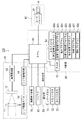
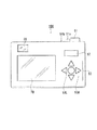
図1は、本発明の第1の実施の形態におけるデジタルカメラの要部構成を示すブロック図である。図2は、同デジタルカメラの背面図である。
図1、図2に示されるように、デジタルカメラ100は、被写体の画像を撮像する撮像部10と、撮像部10が撮像した画像のデータを記録する記録部40と、デジタルカメラ100を操作する操作入力を行う操作部50と、デジタルカメラ100に電力を供給するバッテリ60と、デジタルカメラ100の動作に関する表示を行う画像表示装置70と、上記各構成の動作制御を行う制御部80とを備えている。
【0019】
撮像部10は、レンズ11と、CCD12と、画像処理部13と、レンズ駆動回路14と、レンズ駆動モータ15とにより構成されている。
レンズ11は、CCD12の受光面に被写体の画像を結像する。
CCD12は、受光面に結像された画像に基づく電気信号(アナログ信号)を画像処理部13に出力する。
画像処理部13は、CCD12から入力された電気信号(アナログ信号)をA/D変換し、デジタル画像信号にする。そして、画像処理部13は、そのデジタル画像信号となった画像データを制御部80に出力する。
【0020】
レンズ駆動回路14は、後述する操作部50等から制御部80を介して入力される操作信号(レンズ駆動信号)に基づき、レンズ駆動モータ15にモータ駆動信号を出力する。
レンズ駆動モータ15は、モータ駆動信号に応じて回転駆動し、レンズ11を移動させる。そして、レンズ11は、移動された合焦位置において、CCD12の受光面に被写体の画像を結像する
【0021】
記録部40は、例えば、カードスロット41と、カードスロット41に着脱自在に備えられるメモリーカードAとにより構成されている。
記録部40は、画像処理部13から制御部80を介して入力される画像データをメモリーカードAに記録する。
【0022】
操作部50は、撮像動作(記録動作)の開始を指定するレリーズSW(スイッチ)51、機能モードや撮像モード等の変更を指定するメニューSW52、メモリーカードAに記録された画像の再生の指定や、画像表示装置70の表示画面上で入力を行う位置を指定するためのカーソルSW53等を有し、各SWの操作信号は、制御部80のCPU81に出力される。
【0023】
レリーズSW51は、図2に示されるように、フォーカスSW51aとシャッターSW51bとの機能を有する2段階のスイッチであり、レリーズSW51を半押しした1段階目のフォーカスSW51aが操作されたことに伴い、後述する制御部80の評価値算出手段と合焦位置決定手段とによる合焦位置の決定、つまり、オートフォーカス機能の動作を行うための操作信号が制御部80に出力される。
また、レリーズSW51を全押しした2段階目のシャッターSW51bが操作されたことに伴い、撮像部10が撮像した画像データを記録部40へ記録させるための操作信号が制御部80に出力される。
【0024】
メニューSW52は、例えば、後述するオートフォーカス撮影モード、セミオートフォーカス撮影モード、マニュアルフォーカス撮影モード等の選択、変更を行う際のスイッチであり、選択された各撮影モードによる動作を行うための操作信号が制御部80に出力される。
【0025】
カーソルSW53は、図2に示されるように、左カーソルSW53L、右カーソルSW53Rを有する。左カーソルSW53Lと右カーソルSW53Rは、特に、マニュアル操作により合焦位置調整を行う操作入力キーとしての機能を有する。例えば、左カーソルSW53Lが操作されたことに伴い、レンズ11を至近撮像位置側へ移動させるためのレンズ駆動信号(操作信号)が制御部80に出力され、右カーソルSW53Rが操作されたことに伴い、レンズ11を最遠撮像位置側へ移動させるためのレンズ駆動信号(操作信号)が制御部80に出力される。
【0026】
バッテリ60は、例えば、繰り返し使用可能な充電式二次電池であり、電池スロット(図示略)に装着されて、デジタルカメラ100内の各部に電力を供給する。
【0027】
画像表示装置70は、例えば、LCD等のディスプレイにより構成されており、制御部80により入力された表示信号に従って、所定の画面表示、例えば、デジタルカメラ100の機能モード設定を行う設定入力用画面の表示や、メモリーカードに記録された画像の再生表示等を行う。また、画像表示装置70は、撮像時においては、撮像部10により撮像された画像を連続的に表示するファインダとしての機能を有する。
また、図2に示されるように、デジタルカメラ100には、光学式ファインダ20も設けられている。
【0028】
制御部80は、CPU81と、EEPROM82と、RAM83とで概略構成されている。
CPU81は、EEPROM82に格納されたデジタルカメラ用の制御プログラムに従って、各種の制御動作を実行する。
【0029】
EEPROM82は、電気的に書き換え可能な読み出し専用のメモリで、CPU81によって実行される各種制御プログラムや、各種動作に使用するデータ、情報等を予め記憶、格納している。
本発明においてEEPROM82は、撮像する被写体(被写体光像)の合焦状態を示す評価値を算出する評価値算出プログラム82aや、算出された評価値に基づき被写体に対する合焦位置を決定する合焦位置決定プログラム82bや、算出された評価値と合焦位置とを対応させて表示する表示プログラム82cや、操作部50の操作入力に伴い合焦位置を調整する合焦位置調整プログラム82dや、調整された合焦位置に応じて合焦位置を示す表示を変更する表示変更プログラム82eや、算出された評価値が所定の合焦位置確定条件を満たすか否かを判断する判断プログラム82fや、判断手段によって評価値が所定の合焦位置確定条件を満たさないと判断された場合にその旨の報知を行う報知プログラム82g等を格納するプログラム記憶領域が設けられている。
【0030】
RAM83は、CPU81が上記各種処理プログラムを実行する際に、この各種プログラムをRAM83内の図示しないプログラム格納領域に展開するとともに、CPU81が上記各種処理プログラムを実行する際に生じるデータ等を、図示しないデータ格納領域に一時的に格納する。
【0031】
そして、制御部80は、撮像部10における動作信号や、操作部50における操作信号等に基づく制御、判断等を行い、評価値算出手段、合焦位置決定手段、表示手段、合焦位置調整手段、表示変更手段、判断手段、報知手段として機能する。
より具体的に、制御部80は、評価値算出プログラム82aに基づき評価値算出手段として、レンズ駆動信号を出力し、レンズ11をレンズ駆動モータ15の駆動により至近撮像位置から最遠撮像位置の間を移動させつつ、複数の所定位置において被写体(被写体光像)を撮像し、画像処理部13で処理された画像データの解析を行い、所定位置におけるその被写体光像の合焦状態を示す評価値を算出する制御動作を行う。例えば、この評価値は、画像処理部13で処理された画像データについて特定周波数解析を行い計測される画像データ中に含まれる細かい成分の量に基づき算出され、細かい成分の量が多いほど大きな評価値、少ないほど小さな評価値が算出、設定される。
【0032】
また、制御部80は、合焦位置決定プログラム82bに基づき合焦位置決定手段として、評価値算出手段により算出された評価値に基づき被写体に対する合焦位置を決定する制御動作を行う。例えば、評価値が大きいほど撮像された画像データ中に含まれる細かい成分の量が多いことになるので、評価値が大きいほど、ボケていないシャープな画像であり、ピントがあった合焦位置であるといえる。
つまり、制御部80は、最大の評価値が算出、設定されたレンズ11の位置が合焦位置であると判断する。そして、制御部80は、合焦位置と判断した位置にレンズ11を移動し、配置するためのレンズ駆動信号をレンズ駆動回路14に出力する。
なお、レンズ11が移動され配置される位置と、レンズ11(デジタルカメラ100)からの焦点距離は対応つけられているので、その合焦位置に基づき焦点距離を定めることができる。
【0033】
また、制御部80は、表示プログラム82cに基づき表示手段として、評価値算出手段により算出された評価値と、合焦位置決定手段により決定された合焦位置とを対応させて画像表示装置70に表示する制御動作を行う。例えば、評価値をヒストグラムとして表示し、そのヒストグラムのうち合焦位置に対応する評価値を指し示すマーカーを表示する。
【0034】
また、制御部80は、合焦位置調整プログラム82dに基づき合焦位置調整手段として、操作部50が操作され入力された操作信号(合焦位置調整信号)に基づき、レンズ駆動モータ15の駆動によりレンズ11を移動させる合焦位置の変更、調整する動作制御を行う。
【0035】
また、制御部80は、表示変更プログラム82eに基づき表示変更手段として、合焦位置が、合焦位置調整手段により変更、調整されたことに伴い、画像表示装置70に表示されている合焦位置を示す表示(例えば、その評価値を指し示すマーカー)の位置を変更する動作制御を行う。
【0036】
また、制御部80は、判断プログラム82fに基づき判断手段として、評価値算出手段により算出された評価値が、予め設定された合焦位置確定条件を満たすか否かを判断する動作制御を行う。例えば、最大の評価値と、2番目に大きい評価値との差が所定値以上であれば合焦位置確定条件を満たすと判断し、その差が所定値以下であれば合焦位置確定条件を満たさないと判断する。制御部80が、合焦位置確定条件を満たすと判断すると、合焦位置決定手段により決定された合焦位置は有効であるとしてオートフォーカスする際の基準に用いる。一方、制御部80が、合焦位置確定条件を満たさないと判断すると、後述する報知プログラム82gに基づく報知手段としての動作制御を行う。
【0037】
また、制御部80は、報知プログラム82gに基づき報知手段として、判断手段により予め設定された合焦位置確定条件を満たさないと判断された場合に、所定の態様により、その旨を報知する制御手段を行う。例えば、合焦位置決定手段により決定された合焦位置はオートフォーカスする際の基準には不向き、不十分であり、マニュアル操作による合焦位置(焦点距離)調整を行うべきとの旨を通知、指示するための表示を画像表示装置70に表示する報知を行ったり、図示しない音声出力部から警告音を発したりする報知を行ったりする。
【0038】
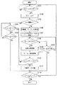
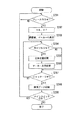
次に、前述のように構成されているデジタルカメラ100の画像の撮像動作におけるオートフォーカス撮影モードついて、図3に基づき説明する。
デジタルカメラ100のメインスイッチがONにされ、デジタルカメラ100がオートフォーカス撮影モードで起動している状態で、レリーズSW51のフォーカスSW51aが操作されたことに伴う操作信号が制御部80に入力されると(ステップS101;YES)、ステップS102へ進む。また、レリーズSW51のフォーカスSW51aが操作されたことに伴う操作信号が制御部80に入力されるまでは(ステップS101;NO)、その状態で待機する。
【0039】
そして、制御部80は、撮像部10における自動露出(AE)を行うとともに、デジタルカメラ100と被写体との距離を評価、判定し、レンズ11を合焦位置に移動させるオートフォーカス(AF)機能に基づく動作を行う(ステップS102)。
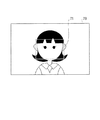
ここで、制御部80は、至近撮像位置から最遠撮像位置の間において、被写体が存在するであろう位置を撮像した画像データの解析により評価値を算出し(評価値算出手段)、評価値が最も大きい位置が合焦位置であると決定する(合焦位置決定手段)。なお、評価値は、後述する図4、図5におけるファインダとしての画像表示装置70における略中央部分の評価領域71に相当する画像の画像データの解析により評価し、設定する。
【0040】
次いで、制御部80は、評価、設定した評価値に基づき、オートフォーカス撮像の信頼性を判断する(ステップS103)。
制御部80が、所定の合焦位置確定条件を満たすと判断し、オートフォーカス撮像の信頼性が高いと判断すると(ステップS103;YES)、ステップS104へ進む。なお、オートフォーカス撮像の信頼性が高い画像とは、例えば、図4に示されるような、画像表示装置70の評価領域71に撮像対象物である被写体が捕らえられている場合などである。
【0041】
そして、レリーズSW51のシャッターSW51bが操作されたことに伴う操作信号が制御部80に入力されると(ステップS104;YES)、ステップS113へ進み、制御部80は、撮像部10が撮像した画像データを記録部40へ記録する(ステップS113)。一方、レリーズSW51のシャッターSW51bが操作されたことに伴う操作信号が制御部80に入力されないと(ステップS104;NO)、ステップS105へ進む。
そして、レリーズSW51のフォーカスSW51aが操作されたことに伴う操作信号が制御部80に入力されていれば(ステップS105;YES)、ステップS104へ戻る。一方、レリーズSW51のフォーカスSW51aが操作されたことに伴う操作信号が制御部80に入力されていないと(ステップS105;NO)、ステップS114へ進む。
【0042】
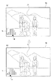
一方、制御部80が、所定の合焦位置確定条件を満たさないと判断し、オートフォーカス撮像の信頼性が低いと判断すると(ステップS103;NO)、制御部80は、図5(a)に示されるように、画像表示装置70の所定の位置に、評価値を表すヒストグラムhと、合焦位置であると決定した評価値を示すマーカーmとを表示する(ステップS106)。なお、オートフォーカス撮像の信頼性が低い画像とは、例えば、図5に示されるような、画像表示装置70の評価領域71に人物とその背景とが捕らえられており、そのどちらが撮像対象物である被写体か(どちらに合焦位置を合わせるか)、制御部80が判断しかねる場合などである。
ここで、制御部80は、暫定的に合焦位置とした最大の評価値を点滅するマーカーmで示すとともに、このようにマーカーmを点滅させて表示することにより、マニュアル操作により合焦位置の調整(マニュアルフォーカス)を行うべきとの旨を報知する(ステップS107)。
【0043】
そして、合焦位置の調整、変更をマニュアル操作により行われず、その操作信号が制御部80に入力されないと(ステップS108;NO)、ステップS109へ進む。
そして、レリーズSW51のフォーカスSW51aが操作されたことに伴う操作信号が制御部80に入力されていれば(ステップS109;YES)、ステップS108へ戻る。一方、レリーズSW51のフォーカスSW51aが操作されたことに伴う操作信号が制御部80に入力されていないと(ステップS109;NO)、ステップS114へ進む。
【0044】
一方、合焦位置の調整、変更をマニュアル操作により行われた操作信号(カーソルSW53の左カーソルSW53L、右カーソルSW53Rが操作されたことに伴う合焦位置調整信号)が制御部80に入力されると(ステップS108;YES)、制御部80は、その操作信号に基づきレンズ11を移動させ、合焦位置を変更する(ステップS110)。次いで、制御部80は、合焦位置の変更に伴い、図5(b)に示されるように、合焦位置である評価値を示すマーカーmの移動(表示変更)を行う(ステップS111)。そして、ステップS112へ進む。
【0045】
レリーズSW51のシャッターSW51bが操作されたことに伴う操作信号が制御部80に入力されると(ステップS112;YES)、制御部80は、撮像部10が撮像した画像データを記録部40へ記録する(ステップS113)。一方、レリーズSW51のシャッターSW51bが操作されたことに伴う操作信号が制御部80に入力されないと(ステップS112;NO)、ステップS108へ戻る。
【0046】
そして、メインスイッチがONであれば(ステップS114;YES)、ステップS201に戻り、メインスイッチがOFFにされれば(ステップS114;NO)、デジタルカメラ100は停止される。
【0047】
このように、本発明のデジタルカメラ100によれば、オートフォーカス撮影モードにより撮像を行う場合、デジタルカメラ100のオートフォーカス機能により合焦位置を決定する基準となる評価値が、所定の合焦位置確定条件を満たす場合には、オートフォーカス撮像が可能であると判断され、通常どおりのオートフォーカス機能に基づくオートフォーカス撮像を行うことができる。
【0048】
また、その合焦位置を決定する基準となる評価値が、所定の合焦位置確定条件を満たさない場合には、オートフォーカス撮像は信頼性が低いと判断され、マニュアル操作による合焦位置、ピント合わせを行うべきである旨が通知、報知される。よって、デジタルカメラ100において、合焦位置の調整、ピント合わせが困難である画像(オートフォーカス撮像の信頼性が低い画像)を撮像する際に、デジタルカメラ100は、無理な合焦位置の調整、ピント合わせを行わずに、使用者に対し、マニュアル操作による合焦位置調整、ピント合わせを行うよう報知し、促すことで、使用者がより好適な合焦位置調整、ピント合わせを行い、好適な撮像を行うことができる。
特に、合焦位置を決定する基準とした評価値とともにその合焦位置が画像表示装置70に表示されるので、デジタルカメラ100が判断、決定した合焦位置に基づき、デジタルカメラ100が合焦位置を決定した基準である評価値を確認しつつ、合焦位置の調整を行うことができるので、容易にピント合わせの調整を行うことができる。
よって、より確実に合焦位置を調整し、より確実なピント合わせを行うことができる。
【0049】
なお、本実施の形態では、ステップS106、S107において、暫定的に合焦位置とした評価値を点滅するマーカーmで示し、暫定的な合焦位置から所望する合焦位置へマニュアル操作により調整するとしたが、暫定的が合焦位置は設定せず、完全にマニュアル操作によって合焦位置調整、ピント合わせを行うようにしてもよい。
【0050】
〔第2の実施の形態〕
次に、本発明の第2の実施の形態について説明する。なお、デジタルカメラ100の構成は第1の実施の形態と同一であるので説明は省略し、デジタルカメラ100の画像の撮像動作におけるセミオートフォーカス撮影モードついて、図6に基づき説明する。
【0051】
デジタルカメラ100のメインスイッチがONにされ、デジタルカメラ100がオートフォーカス撮影モードで起動している状態で、レリーズSW51のフォーカスSW51aが操作されたことに伴う操作信号が制御部80に入力されると(ステップS201;YES)、制御部80は、撮像部10における自動露出(AE)を行うとともに、デジタルカメラ100と被写体との距離を評価、判定し、レンズ11を合焦位置に移動させるオートフォーカス機能(AF)に基づく動作を行う(ステップS202)。
ここで、制御部80は、至近撮像位置から最遠撮像位置の間において、被写体が存在するであろう位置を撮像した画像データの解析により評価値を算出し(評価値算出手段)、評価値が最も大きい位置が合焦位置であると決定する(合焦位置決定手段)。なお、評価値は、後述する図7におけるファインダとしての画像表示装置70における略中央部分の評価領域71に相当する画像の画像データの解析により評価し、設定する。
【0052】
また、レリーズSW51のフォーカスSW51aが操作されたことに伴う操作信号が制御部80に入力されるまでは(ステップS201;NO)、その状態で待機する。
【0053】
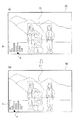
次いで、制御部80は、図7(a)に示されるように、画像表示装置70の所定の位置に、評価値を表すヒストグラムhと、合焦位置であると判断した評価値を示すマーカーmとを表示する(ステップS203)。なお、ここで、制御部80は、画像表示装置70の評価領域71に捕らえられている二人の人物の何れか、或いは評価領域71に捕らえられている人物とその背景との何れかが、合焦位置であると判断し、合焦位置の候補である評価値が2つのピークのヒストグラムとして表示されている。
【0054】
そして、合焦位置の調整、変更をマニュアル操作により行われた操作信号(カーソルSW53の左カーソルSW53L、右カーソルSW53Rが操作されたことに伴う合焦位置調整信号)が制御部80に入力されると(ステップS204;YES)、制御部80は、その操作信号に基づきレンズ11を移動させ、合焦位置を変更する(ステップS205)。次いで、制御部80は、合焦位置の変更に伴い、図7(b)に示されるように、合焦位置である評価値を示すマーカーmの移動(表示変更)を行う(ステップS206)。そして、ステップS207へ進む。
一方、合焦位置の調整、変更をマニュアル操作により行われず、その操作信号が制御部80に入力されないと(ステップS204;NO)、ステップS207へ進む。
【0055】
レリーズSW51のシャッターSW51bが操作されたことに伴う操作信号が制御部80に入力されると(ステップS207;YES)、制御部80は、撮像部10が撮像した画像データを記録部40へ記録する(ステップS208)。一方、レリーズSW51のシャッターSW51bが操作されたことに伴う操作信号が制御部80に入力されないと(ステップS207;NO)、ステップS204へ戻る。
【0056】
そして、メインスイッチがONであれば(ステップS109;YES)、ステップS201に戻り、メインスイッチがOFFにされれば(ステップS209;NO)、デジタルカメラ100は停止される。
【0057】
このように、本発明のデジタルカメラ100によれば、セミオートフォーカス撮影モードにより撮像を行う場合、デジタルカメラ100のオートフォーカス機能により決定した合焦位置が、合焦位置を決定する基準とした評価値とともに画像表示装置70に表示されるので、デジタルカメラ100が判断、決定した合焦位置を、評価値の分布のなかの位置として確認することができる。よって、その合焦位置の精度や、他の合焦位置の候補となりえる評価値の有無を確認することができる。
また、デジタルカメラ100のオートフォーカス機能により判断、決定された合焦位置から、マニュアル操作によって合焦位置の調整、つまり、ピント合わせの微調整を行うことができる。特に、デジタルカメラ100が合焦位置を決定した基準である評価値を確認しつつ、合焦位置の調整を行うことができるので、容易にピント合わせの微調整を行うことができる。
よって、より確実に合焦位置を調整し、より確実なピント合わせを行うことができる。
【0058】
また、従来のオートフォーカスカメラにおいては、ピントが合った撮像を行うことがその機能であったが、本発明のデジタルカメラ100においては、オートフォーカス機能により合焦位置を定め、ピントが合った状態から、マニュアル操作によって合焦位置を移動させ、故意にピントをずらすことによる「ぼかし」画像の撮像を行うことができる。
【0059】
なお、以上の実施の形態においては、評価値を表すヒストグラムhと合焦位置であると決定した評価値を示すマーカーmとを画像表示装置70に表示するとしたが、本発明はこれに限定されるものではなく、光学式ファインダ20で視認可能なように表示してもよい。
また、被写体に対する合焦位置を評価するための評価領域71を、図4、図5、図7に示されるように、撮像範囲のほぼ中央の一箇所に有する例で説明したが、評価領域は複数(例えば、撮像範囲中の左右二箇所)有していてもよく、複数の評価領域を有する場合には、その評価領域毎に合焦状態を示すヒストグラムを表示してもよい。なお、それらの表示を複数同時に行ってもよく、また、選択した評価領域のもののみを表示してもよい。
【0060】
また、以上の実施の形態においては、制御部80にEEPROM82を備える構成を例に説明したが、本発明はこれに限定されるものではなく、例えば、FLASH−ROMなどのように、電源(バッテリ60)がオフになっても記憶が保持できるメモリであればよい。
また、カードスロットの数も任意であり、複数のメモリーカードを使用できるようにしてもよい。
【0061】
また、デジタルカメラ100において、オートフォーカス機能を使用せず、マニュアルフォーカス撮影モードにおいて、マニュアルフォーカス撮影を行ってもよい。
【0062】
また、その他、具体的な細部構造等についても適宜に変更可能であることは勿論である。
【0063】
【発明の効果】
請求項1記載の発明によれば、評価値算出手段が至近撮像位置から最遠撮像位置までの間の複数の所定位置に対応するレンズ位置での被写体光像の合焦状態を示す評価値を算出し、算出された複数の所定位置の評価値に基づいて、合焦位置決定手段が合焦位置を決定する。そして、表示手段が、その算出された複数の所定位置の評価値と、決定された合焦位置とを対応させて表示する。
よって、カメラは、オートフォーカス機能により決定した合焦位置を、合焦位置を決定する基準とした評価値とともに表示することができるので、カメラの使用者は、その合焦位置についての確認、例えば、どのように分布する評価値から合焦位置に対応する評価値が選択、決定されたかという確認や、決定された合焦位置に対応する評価値とそれ以外の評価値との差の程度、つまり、合焦位置に対応する評価値と類似する評価値の有無の確認などを行うことができる。従って、オートフォーカス機能を利用し、被写体を撮像する場合であっても、合焦位置の適正程度や、ピントの合い具合を確認することができる。
そして、その表示をピント合わせの指標とすることで、オートフォーカスをし直す等により確実に合焦位置を調整し、より確実なピント合わせを行うことができる。
【0064】
請求項2記載の発明によれば、請求項1に記載の発明と同様の作用を奏するとともに、合焦位置調整手段が合焦位置決定手段により決定された合焦位置をマニュアル操作による調整を行い、調整された合焦位置に応じて、表示変更手段が表示手段によって表示される合焦位置の変更を行う。
つまり、カメラが、オートフォーカス機能により決定した合焦位置を、マニュアル操作により調整することができるので、オートフォーカス機能により決定した合焦位置を微調整し、所望する合焦位置に変更することができる。特に、合焦位置を決定する基準とした評価値とともに合焦位置が表示されているので、その評価値を参考にすることで容易に合焦位置の調整、変更を行うことができる。
また、調整、変更された合焦位置に応じて、その表示も変更されるので、変更履歴を確認しつつ、合焦位置の調整、変更を行うことができる。
よって、より確実に合焦位置を調整し、より確実なピント合わせを行うことができる。
【0065】
請求項3記載の発明によれば、評価値算出手段が至近撮像位置から最遠撮像位置までの間の複数の所定位置に対応するレンズ位置での被写体光像の合焦状態を示す評価値を算出し、算出された複数の所定位置の評価値に基づいて、合焦位置決定手段が合焦位置を決定する。そして、判断手段が、その算出された評価値が予め設定された合焦位置確定条件を満たすか否かを判断し、所定の合焦位置確定条件を満たさないと判断した場合に、表示手段が、その算出された複数の所定位置の評価値と、決定された合焦位置とを対応させて表示する。
つまり、カメラは、オートフォーカス機能により決定した合焦位置に関して、その合焦位置を決定する基準とした評価値が予め設定された合焦位置確定条件を満たすか否かを判断することで、適正な合焦位置か否かの判断を行う。そして、その評価値が、所定の合焦位置確定条件を満たさないと判断した場合に、表示手段が、その算出された複数の所定位置の評価値と、決定された合焦位置とを対応させて表示するので、カメラの使用者は、決定された合焦位置が適正か否かの確認、例えば、決定された合焦位置に対応する評価値と類似する評価値の有無の確認などを行うことができる。
そして、その表示をピント合わせの指標とすることで、より確実に合焦位置を調整し、より確実なピント合わせを行うことができる。
【0066】
請求項4記載の発明によれば、請求項3に記載の発明と同様の作用を奏するとともに、合焦位置調整手段が合焦位置決定手段により決定された合焦位置をマニュアル操作による調整を行い、調整された合焦位置に応じて、表示変更手段が表示手段によって表示される合焦位置の変更を行う。
つまり、カメラが、オートフォーカス機能により決定した合焦位置を、マニュアル操作により調整することができるので、オートフォーカス機能により決定した合焦位置を微調整し、所望する合焦位置に変更することができる。また、合焦位置を決定する基準とした評価値とともに合焦位置が表示されているので、その評価値を参考にすることで容易に合焦位置の調整、変更を行うことができる。また、調整、変更された合焦位置に応じて、その表示も変更されるので、変更履歴を確認しつつ、合焦位置の調整、変更を行うことができる。
特に、その合焦位置を決定する基準とした評価値が、所定の合焦位置確定条件を満たさず、オートフォーカス機能が不十分である可能性がある場合に、その算出された複数の所定位置の評価値と、決定された合焦位置とが対応するように表示させて、その合焦位置の調整を行うことにより、より確実に合焦位置を調整し、より確実なピント合わせを行うことができる。
【0067】
請求項5記載の発明によれば、請求項3又は4に記載の発明と同様の作用を奏するとともに、判断手段が、その算出された評価値が予め設定された合焦位置確定条件を満たさないと判断した場合に、報知手段が所定の態様により、判断手段が行ったその判断を通知する報知を行う。
つまり、カメラは、オートフォーカス機能により決定した合焦位置に関して、その合焦位置を決定する基準とした評価値が予め設定された合焦位置確定条件を満たすか否かを判断することで、適正な合焦位置か否かの判断を行う。そして、カメラの判断手段が、その評価値は所定の合焦位置確定条件を満たさないと判断した場合に、報知手段が所定の態様により、評価値は予め設定された合焦位置確定条件を満たさないと判断された旨を通知する報知を行う。
よって、カメラの使用者は、決定された合焦位置が適正でないことを認識す ることができるので、撮像動作のやり直しや、合焦位置の調整を行うなど対 処することにより、より確実に合焦位置を調整し、より確実なピント合わせ を行うことができる。
【図面の簡単な説明】
【図1】本発明にかかるデジタルカメラの要部構成を示すブロック図である。
【図2】本発明にかかるデジタルカメラの背面図である。
【図3】本発明の第1の実施の形態におけるデジタルカメラの撮像動作を示すフローチャートである。
【図4】本発明のデジタルカメラの画像表示装置に表示される被写体の説明図である。
【図5】本発明のデジタルカメラの画像表示装置に表示される被写体の説明図である。
【図6】本発明の第2の実施の形態におけるデジタルカメラの撮像動作を示すフローチャートである。
【図7】本発明のデジタルカメラの画像表示装置に表示される被写体の説明図である。
【符号の説明】
10 撮像部
11 レンズ
12 CCD
13 画像処理部
14 レンズ駆動回路
15 レンズ駆動モータ
40 記録部
50 操作部
51 レリーズSW
52 メニューSW
53 カーソルSW
70 画像表示装置
71 評価領域
80 制御部
81 CPU(評価値算出手段、合焦位置決定手段、表示手段、合焦位置調整手段、表示変更手段、判断手段、報知手段)
82 EEPROM
82a 評価値算出プログラム(評価値算出手段)
82b 合焦位置決定プログラム(合焦位置決定手段)
82c 表示プログラム(表示手段)
82d 合焦位置調整プログラム(合焦位置調整手段)
82e 表示変更プログラム(表示変更手段)
82f 判断プログラム(判断手段)
82g 報知プログラム(報知手段)
83 RAM
100 デジタルカメラ(カメラ)[0001]
TECHNICAL FIELD OF THE INVENTION
The present invention relates to a camera, and more particularly, to a camera capable of performing autofocus adjustment and focus adjustment by manual operation.
[0002]
[Prior art]
2. Description of the Related Art Conventionally, an autofocus camera that automatically performs focus adjustment (focusing) has been known. Autofocus cameras automatically focus on most subjects, but some subjects are difficult to focus with autofocus, and some can be more reliably achieved by focusing manually.
There is known a camera capable of confirming the degree of focus (in-focus state) when performing focusing by such a manual operation (for example, see Patent Document 1).
[0003]
[Patent Document 1]
JP-A-6-113184
[0004]
[Problems to be solved by the invention]
However, in the case of Patent Document 1, it may be difficult for a person who is accustomed to using an autofocus camera to focus well by manual operation itself. It was sometimes difficult to confirm.
[0005]
It is an object of the present invention to provide a camera having an autofocus function, which can perform focusing more reliably.
[0006]
[Means for Solving the Problems]
In order to solve the above problems, the invention described in claim 1 is
Evaluation value calculation means for calculating an evaluation value indicating a focus state of the subject light image at a lens position corresponding to a plurality of predetermined positions from the closest imaging position to the farthest imaging position,
A focus position determination unit that determines a focus position based on the evaluation values of the plurality of predetermined positions calculated by the evaluation value calculation unit;
Display means for displaying the evaluation values of the plurality of predetermined positions calculated by the evaluation value calculation means and the focus position determined by the focus position determination means in association with each other;
It is characterized by having.
[0007]
According to the first aspect of the present invention, the evaluation value calculating means calculates the evaluation value indicating the in-focus state of the subject light image at the lens positions corresponding to the plurality of predetermined positions from the closest imaging position to the farthest imaging position. The in-focus position determining means determines the in-focus position based on the calculated evaluation values of the plurality of predetermined positions. Then, the display means displays the calculated evaluation values of the plurality of predetermined positions in correspondence with the determined in-focus positions.
Therefore, the camera can display the focus position determined by the autofocus function together with the evaluation value used as the reference for determining the focus position, so that the user of the camera can check the focus position, for example, The evaluation value corresponding to the in-focus position is selected and determined from how the evaluation values are distributed, and the degree of difference between the evaluation value corresponding to the determined in-focus position and the other evaluation values, That is, it is possible to check whether or not there is an evaluation value similar to the evaluation value corresponding to the in-focus position. Therefore, even when the subject is imaged using the autofocus function, it is possible to confirm the appropriate degree of the focus position and the degree of focus.
Then, by using the display as an index for focusing, the focus position can be surely adjusted by performing auto-focusing again, and more accurate focusing can be performed.
[0008]
Note that the plurality of predetermined positions are, for example, arbitrary intervals (for example, 1 m) from the position of 0 m from the camera as the closest imaging position to the position of ∞ (infinity) from the camera as the farthest imaging position. When the movement of the lens of the camera is controlled by pulse driving control, the reference position is a plurality of reference positions set for a predetermined number of pulses (for example, every 10 pulses).
[0009]
According to a second aspect of the present invention, in the camera according to the first aspect,
A focus position adjustment unit that adjusts the focus position determined by the focus position determination unit by manual operation;
Display changing means for changing a focus position displayed by the display means according to the focus position adjusted by the focus position adjusting means;
It is characterized by having.
[0010]
According to the second aspect of the invention, the same operation as that of the first aspect of the invention is provided, and the focus position adjusting means adjusts the focus position determined by the focus position determination means by manual operation. The display changing means changes the focus position displayed by the display means according to the adjusted focus position.
That is, since the camera can manually adjust the focus position determined by the autofocus function, it is possible to finely adjust the focus position determined by the autofocus function and change the focus position to a desired focus position. it can. In particular, since the in-focus position is displayed together with the evaluation value used as a reference for determining the in-focus position, the in-focus position can be easily adjusted and changed by referring to the evaluation value.
In addition, since the display is changed according to the adjusted and changed focus position, the focus position can be adjusted and changed while checking the change history.
Therefore, the in-focus position can be more reliably adjusted, and more accurate focusing can be performed.
[0011]
The invention according to claim 3 is
Evaluation value calculation means for calculating an evaluation value indicating a focus state of the subject light image at a lens position corresponding to a plurality of predetermined positions from the closest imaging position to the farthest imaging position,
A focus position determination unit that determines a focus position based on the evaluation values of the plurality of predetermined positions calculated by the evaluation value calculation unit;
Determining means for determining whether or not the evaluation values of the plurality of predetermined positions calculated by the evaluation value calculating means satisfy a preset focus position determination condition;
When the evaluation means determines that the evaluation values at the plurality of predetermined positions calculated by the evaluation value calculation means do not satisfy a preset focus position determination condition, the evaluation value calculation means calculates Display means for displaying the evaluation values of the plurality of predetermined positions and the focus position determined by the focus position determination means in association with each other;
It is characterized by having.
[0012]
According to the third aspect of the present invention, the evaluation value calculating means calculates the evaluation value indicating the in-focus state of the subject light image at the lens positions corresponding to the plurality of predetermined positions from the closest imaging position to the farthest imaging position. The in-focus position determining means determines the in-focus position based on the calculated evaluation values of the plurality of predetermined positions. Then, the determining means determines whether or not the calculated evaluation value satisfies a preset focusing position determination condition. If the determining means determines that the predetermined focusing position determination condition is not satisfied, the display means determines The calculated evaluation values of the plurality of predetermined positions are displayed in association with the determined in-focus positions.
That is, the camera determines whether or not the evaluation value used as the reference for determining the focus position with respect to the focus position determined by the autofocus function satisfies a preset focus position determination condition. It is determined whether or not the focus position is appropriate. When it is determined that the evaluation value does not satisfy the predetermined focus position determination condition, the display unit associates the calculated evaluation values of the plurality of predetermined positions with the determined focus position. Display, the user of the camera checks whether or not the determined focus position is appropriate, for example, whether or not there is an evaluation value similar to the evaluation value corresponding to the determined focus position. be able to.
Then, by using the display as an index for focusing, the in-focus position can be more reliably adjusted, and more accurate focusing can be performed.
[0013]
Note that the plurality of predetermined positions are, for example, at equal intervals (for example, every 1 m) from a position 0 m from the camera as the closest imaging position to a position ∞ (infinity) from the camera as the farthest imaging position. ) Means a plurality of reference positions.
[0014]
According to a fourth aspect of the present invention, in the camera according to the third aspect,
A focus position adjustment unit that adjusts the focus position determined by the focus position determination unit by manual operation;
Display changing means for changing a focus position displayed by the display means according to the focus position adjusted by the focus position adjusting means;
It is characterized by having.
[0015]
According to the fourth aspect of the invention, the same operation as the third aspect of the invention is achieved, and the focus position adjusting means adjusts the focus position determined by the focus position determination means by manual operation. The display changing means changes the focus position displayed by the display means according to the adjusted focus position.
That is, since the camera can manually adjust the focus position determined by the autofocus function, it is possible to finely adjust the focus position determined by the autofocus function and change the focus position to a desired focus position. it can. Further, since the in-focus position is displayed together with the evaluation value serving as a reference for determining the in-focus position, the in-focus position can be easily adjusted or changed by referring to the evaluation value. In addition, since the display is changed according to the adjusted and changed focus position, the focus position can be adjusted and changed while checking the change history.
In particular, when the evaluation value used as a reference for determining the in-focus position does not satisfy the predetermined in-focus position determination condition and there is a possibility that the auto-focus function is insufficient, the calculated plurality of predetermined positions are determined. By displaying the evaluation value of and the determined in-focus position so as to correspond to each other, and adjusting the in-focus position, the in-focus position can be more reliably adjusted, and more accurate focusing can be performed. Can be.
[0016]
According to a fifth aspect of the present invention, in the camera according to the third or fourth aspect,
In a case where the determination means determines that the evaluation values of the plurality of predetermined positions calculated by the evaluation value calculation means do not satisfy a preset focus position determination condition, notification of a predetermined mode is performed. It is characterized by having a notifying means.
[0017]
According to the fifth aspect of the invention, the same operation as the third or fourth aspect of the invention is achieved, and the judging means determines that the calculated evaluation value does not satisfy the preset focus position determination condition. When it is determined that the notification is made, the notification means notifies the determination performed by the determination means in a predetermined manner.
That is, the camera determines whether or not the evaluation value used as the reference for determining the focus position with respect to the focus position determined by the autofocus function satisfies a preset focus position determination condition. It is determined whether or not the focus position is appropriate. Then, when the determination means of the camera determines that the evaluation value does not satisfy the predetermined focus position determination condition, the notifying means determines that the evaluation value satisfies the preset focus position determination condition in a predetermined manner. A notification is sent to notify that it has not been determined.
Therefore, since the user of the camera can recognize that the determined focusing position is not appropriate, focusing can be performed more reliably by re-taking the imaging operation or adjusting the focusing position. By adjusting the position, more accurate focusing can be performed.
[0018]
BEST MODE FOR CARRYING OUT THE INVENTION
Hereinafter, an embodiment of the present invention will be described with reference to FIGS.
[First Embodiment]
FIG. 1 is a block diagram showing a main configuration of a digital camera according to the first embodiment of the present invention. FIG. 2 is a rear view of the digital camera.
As shown in FIGS. 1 and 2, the
[0019]
The
The
The
The
[0020]
The
The lens drive
[0021]
The
The
[0022]
The
[0023]
As shown in FIG. 2, the
In addition, an operation signal for causing the
[0024]
The
[0025]
As shown in FIG. 2, the cursor SW53 has a left cursor SW53L and a right cursor SW53R. In particular, the left cursor SW53L and the right cursor SW53R have a function as operation input keys for adjusting a focus position by manual operation. For example, in response to the operation of the left cursor SW53L, a lens drive signal (operation signal) for moving the
[0026]
The
[0027]
The
As shown in FIG. 2, the
[0028]
The
The
[0029]
The
In the present invention, the
[0030]
When the
[0031]
The
More specifically, the
[0032]
Further, the
That is, the
Since the position where the
[0033]
Further, the
[0034]
In addition, the
[0035]
In addition, the
[0036]
Further, the
[0037]
Further, the
[0038]
Next, an autofocus photographing mode in an image photographing operation of the
When the main switch of the
[0039]
Then, the
Here, the
[0040]
Next, the
When the
[0041]
Then, when an operation signal associated with the operation of the
If an operation signal accompanying the operation of the
[0042]
On the other hand, when the
Here, the
[0043]
If the focus position is not adjusted or changed by manual operation, and the operation signal is not input to the control unit 80 (step S108; NO), the process proceeds to step S109.
Then, if an operation signal accompanying the operation of the
[0044]
On the other hand, an operation signal (a focus position adjustment signal resulting from operation of the left cursor SW53L and the right cursor SW53R of the cursor SW53) in which the focus position is adjusted and changed by a manual operation is input to the
[0045]
When an operation signal associated with the operation of the
[0046]
If the main switch is ON (step S114; YES), the process returns to step S201, and if the main switch is turned OFF (step S114; NO), the
[0047]
As described above, according to the
[0048]
If the evaluation value serving as a reference for determining the in-focus position does not satisfy the predetermined in-focus position determination condition, the autofocus imaging is determined to be unreliable, and the in-focus position and the in-focus position by manual operation are determined. A notification that adjustment should be performed is notified and notified. Therefore, when the
In particular, since the in-focus position is displayed on the
Therefore, the in-focus position can be more reliably adjusted, and more accurate focusing can be performed.
[0049]
In this embodiment, in steps S106 and S107, the evaluation value temporarily set as the focus position is indicated by a blinking marker m, and the temporary focus position is adjusted to a desired focus position by manual operation. However, the focus position may not be set temporarily, but the focus position adjustment and the focus adjustment may be performed completely manually.
[0050]
[Second embodiment]
Next, a second embodiment of the present invention will be described. Note that the configuration of the
[0051]
When the main switch of the
Here, the
[0052]
In addition, the
[0053]
Next, as shown in FIG. 7A, the
[0054]
Then, an operation signal (a focus position adjustment signal resulting from operation of the left cursor SW53L and the right cursor SW53R of the cursor SW53) in which adjustment and change of the focus position are performed by a manual operation is input to the
On the other hand, if the focus position is not adjusted or changed by manual operation, and the operation signal is not input to the control unit 80 (step S204; NO), the process proceeds to step S207.
[0055]
When an operation signal associated with the operation of the
[0056]
If the main switch is ON (step S109; YES), the process returns to step S201. If the main switch is turned OFF (step S209; NO), the
[0057]
As described above, according to the
In addition, from the focus position determined and determined by the autofocus function of the
Therefore, the in-focus position can be more reliably adjusted, and more accurate focusing can be performed.
[0058]
Further, in a conventional autofocus camera, the function is to perform in-focus imaging, but in the
[0059]
In the above embodiment, the histogram h indicating the evaluation value and the marker m indicating the evaluation value determined to be the in-focus position are displayed on the
In addition, as shown in FIGS. 4, 5, and 7, the
[0060]
Further, in the above-described embodiment, the configuration in which the
Also, the number of card slots is arbitrary, and a plurality of memory cards may be used.
[0061]
In the
[0062]
In addition, it goes without saying that specific detailed structures and the like can be appropriately changed.
[0063]
【The invention's effect】
According to the first aspect of the present invention, the evaluation value calculating means calculates the evaluation value indicating the in-focus state of the subject light image at the lens positions corresponding to the plurality of predetermined positions from the closest imaging position to the farthest imaging position. The in-focus position determining means determines the in-focus position based on the calculated evaluation values of the plurality of predetermined positions. Then, the display means displays the calculated evaluation values of the plurality of predetermined positions in correspondence with the determined in-focus positions.
Therefore, the camera can display the focus position determined by the autofocus function together with the evaluation value used as the reference for determining the focus position, so that the user of the camera can check the focus position, for example, The evaluation value corresponding to the in-focus position is selected and determined from how the evaluation values are distributed, and the degree of difference between the evaluation value corresponding to the determined in-focus position and the other evaluation values, That is, it is possible to check whether or not there is an evaluation value similar to the evaluation value corresponding to the in-focus position. Therefore, even when the subject is imaged using the autofocus function, it is possible to confirm the appropriate degree of the focus position and the degree of focus.
Then, by using the display as an index for focusing, the focus position can be surely adjusted by performing auto-focusing again, and more accurate focusing can be performed.
[0064]
According to the second aspect of the invention, the same operation as that of the first aspect of the invention is provided, and the focus position adjusting means adjusts the focus position determined by the focus position determination means by manual operation. The display changing means changes the focus position displayed by the display means according to the adjusted focus position.
That is, since the camera can manually adjust the focus position determined by the autofocus function, it is possible to finely adjust the focus position determined by the autofocus function and change the focus position to a desired focus position. it can. In particular, since the in-focus position is displayed together with the evaluation value used as a reference for determining the in-focus position, the in-focus position can be easily adjusted and changed by referring to the evaluation value.
In addition, since the display is changed according to the adjusted and changed focus position, the focus position can be adjusted and changed while checking the change history.
Therefore, the in-focus position can be more reliably adjusted, and more accurate focusing can be performed.
[0065]
According to the third aspect of the present invention, the evaluation value calculating means calculates the evaluation value indicating the in-focus state of the subject light image at the lens positions corresponding to the plurality of predetermined positions from the closest imaging position to the farthest imaging position. The in-focus position determining means determines the in-focus position based on the calculated evaluation values of the plurality of predetermined positions. Then, the determining means determines whether or not the calculated evaluation value satisfies a preset focusing position determination condition. If the determining means determines that the predetermined focusing position determination condition is not satisfied, the display means determines The calculated evaluation values of the plurality of predetermined positions are displayed in association with the determined in-focus positions.
That is, the camera determines whether or not the evaluation value used as the reference for determining the focus position with respect to the focus position determined by the autofocus function satisfies a preset focus position determination condition. It is determined whether or not the focus position is appropriate. When it is determined that the evaluation value does not satisfy the predetermined focus position determination condition, the display unit associates the calculated evaluation values of the plurality of predetermined positions with the determined focus position. Display, the user of the camera checks whether or not the determined focus position is appropriate, for example, whether or not there is an evaluation value similar to the evaluation value corresponding to the determined focus position. be able to.
Then, by using the display as an index for focusing, the in-focus position can be more reliably adjusted, and more accurate focusing can be performed.
[0066]
According to the fourth aspect of the invention, the same operation as the third aspect of the invention is achieved, and the focus position adjusting means adjusts the focus position determined by the focus position determination means by manual operation. The display changing means changes the focus position displayed by the display means according to the adjusted focus position.
That is, since the camera can manually adjust the focus position determined by the autofocus function, it is possible to finely adjust the focus position determined by the autofocus function and change the focus position to a desired focus position. it can. Further, since the in-focus position is displayed together with the evaluation value serving as a reference for determining the in-focus position, the in-focus position can be easily adjusted or changed by referring to the evaluation value. In addition, since the display is changed according to the adjusted and changed focus position, the focus position can be adjusted and changed while checking the change history.
In particular, when the evaluation value used as a reference for determining the in-focus position does not satisfy the predetermined in-focus position determination condition and there is a possibility that the auto-focus function is insufficient, the calculated plurality of predetermined positions are determined. By displaying the evaluation value of and the determined in-focus position so as to correspond to each other, and adjusting the in-focus position, the in-focus position can be more reliably adjusted, and more accurate focusing can be performed. Can be.
[0067]
According to the fifth aspect of the invention, the same operation as the third or fourth aspect of the invention is achieved, and the judging means determines that the calculated evaluation value does not satisfy the preset focus position determination condition. When it is determined that the notification is made, the notification means notifies the determination performed by the determination means in a predetermined manner.
That is, the camera determines whether or not the evaluation value used as the reference for determining the focus position with respect to the focus position determined by the autofocus function satisfies a preset focus position determination condition. It is determined whether or not the focus position is appropriate. Then, when the determination means of the camera determines that the evaluation value does not satisfy the predetermined focus position determination condition, the notifying means determines that the evaluation value satisfies the preset focus position determination condition in a predetermined manner. A notification is sent to notify that it has not been determined.
Therefore, the user of the camera can recognize that the determined focus position is not appropriate, so that the user can more reliably focus by retrying the imaging operation or adjusting the focus position. The focus position can be adjusted to achieve more accurate focusing.
[Brief description of the drawings]
FIG. 1 is a block diagram illustrating a main configuration of a digital camera according to the present invention.
FIG. 2 is a rear view of the digital camera according to the present invention.
FIG. 3 is a flowchart illustrating an imaging operation of the digital camera according to the first embodiment of the present invention.
FIG. 4 is an explanatory diagram of a subject displayed on the image display device of the digital camera of the present invention.
FIG. 5 is an explanatory diagram of a subject displayed on the image display device of the digital camera of the present invention.
FIG. 6 is a flowchart illustrating an imaging operation of the digital camera according to the second embodiment of the present invention.
FIG. 7 is an explanatory diagram of a subject displayed on the image display device of the digital camera of the present invention.
[Explanation of symbols]
10 Imaging unit
11 lenses
12 CCD
13 Image processing unit
14 Lens drive circuit
15 Lens drive motor
40 Recorder
50 Operation unit
51 Release SW
52 Menu SW
53 Cursor SW
70 Image display device
71 Evaluation area
80 control unit
81 CPU (evaluation value calculation means, focus position determination means, display means, focus position adjustment means, display change means, determination means, notification means)
82 EEPROM
82a evaluation value calculation program (evaluation value calculation means)
82b In-focus position determination program (in-focus position determination means)
82c display program (display means)
82d Focusing position adjustment program (Focusing position adjusting means)
82e display change program (display change means)
82f judgment program (judgment means)
82g notification program (notification means)
83 RAM
100 Digital camera (camera)
Claims (5)
前記評価値算出手段により算出された前記複数の所定位置の評価値に基づいて、合焦位置を決定する合焦位置決定手段と、
前記評価値算出手段により算出された前記複数の所定位置の評価値と、前記合焦位置決定手段により決定された合焦位置とを対応させて表示する表示手段と、
を備えることを特徴とするカメラ。Evaluation value calculation means for calculating an evaluation value indicating a focus state of the subject light image at a lens position corresponding to a plurality of predetermined positions from the closest imaging position to the farthest imaging position,
A focus position determination unit that determines a focus position based on the evaluation values of the plurality of predetermined positions calculated by the evaluation value calculation unit;
Display means for displaying the evaluation values of the plurality of predetermined positions calculated by the evaluation value calculation means and the focus position determined by the focus position determination means in association with each other;
A camera comprising:
前記合焦位置調整手段により調整された合焦位置に応じて、前記表示手段によって表示される合焦位置の変更を行う表示変更手段と、
を備えることを特徴とする請求項1に記載のカメラ。A focus position adjustment unit that adjusts the focus position determined by the focus position determination unit by manual operation;
Display changing means for changing a focus position displayed by the display means according to the focus position adjusted by the focus position adjusting means;
The camera according to claim 1, further comprising:
前記評価値算出手段により算出された前記複数の所定位置の評価値に基づいて、合焦位置を決定する合焦位置決定手段と、
前記評価値算出手段により算出された前記複数の所定位置の評価値が、予め設定された合焦位置確定条件を満たすか否かを判断する判断手段と、
前記判断手段によって、前記評価値算出手段により算出された前記複数の所定位置の評価値が、予め設定された合焦位置確定条件を満たさないと判断された場合に、前記評価値算出手段により算出された前記複数の所定位置の評価値と、前記合焦位置決定手段により決定された合焦位置とを対応させて表示する表示手段と、
を備えることを特徴とするカメラ。Evaluation value calculation means for calculating an evaluation value indicating a focus state of the subject light image at a lens position corresponding to a plurality of predetermined positions from the closest imaging position to the farthest imaging position,
A focus position determination unit that determines a focus position based on the evaluation values of the plurality of predetermined positions calculated by the evaluation value calculation unit;
Determining means for determining whether or not the evaluation values of the plurality of predetermined positions calculated by the evaluation value calculating means satisfy a preset focus position determination condition;
When the evaluation means determines that the evaluation values at the plurality of predetermined positions calculated by the evaluation value calculation means do not satisfy a preset focus position determination condition, the evaluation value calculation means calculates Display means for displaying the evaluation values of the plurality of predetermined positions and the focus position determined by the focus position determination means in association with each other;
A camera comprising:
前記合焦位置調整手段により調整された合焦位置に応じて、前記表示手段によって表示される合焦位置の変更を行う表示変更手段と、
を備えることを特徴とする請求項3に記載のカメラ。A focus position adjustment unit that adjusts the focus position determined by the focus position determination unit by manual operation;
Display changing means for changing a focus position displayed by the display means according to the focus position adjusted by the focus position adjusting means;
The camera according to claim 3, further comprising:
Priority Applications (1)
| Application Number | Priority Date | Filing Date | Title |
|---|---|---|---|
| JP2003055348A JP2004264635A (en) | 2003-03-03 | 2003-03-03 | camera |
Applications Claiming Priority (1)
| Application Number | Priority Date | Filing Date | Title |
|---|---|---|---|
| JP2003055348A JP2004264635A (en) | 2003-03-03 | 2003-03-03 | camera |
Publications (1)
| Publication Number | Publication Date |
|---|---|
| JP2004264635A true JP2004264635A (en) | 2004-09-24 |
Family
ID=33119386
Family Applications (1)
| Application Number | Title | Priority Date | Filing Date |
|---|---|---|---|
| JP2003055348A Pending JP2004264635A (en) | 2003-03-03 | 2003-03-03 | camera |
Country Status (1)
| Country | Link |
|---|---|
| JP (1) | JP2004264635A (en) |
Cited By (5)
| Publication number | Priority date | Publication date | Assignee | Title |
|---|---|---|---|---|
| JP2010266524A (en) * | 2009-05-12 | 2010-11-25 | Canon Inc | Optical equipment |
| JP2011085945A (en) * | 2010-12-02 | 2011-04-28 | Casio Computer Co Ltd | Photographing device and program |
| JP2013109271A (en) * | 2011-11-24 | 2013-06-06 | Keyence Corp | Image processor, focus adjustment method, and computer program |
| JP2021005064A (en) * | 2019-06-27 | 2021-01-14 | パナソニックIpマネジメント株式会社 | Imaging apparatus |
| US11924549B2 (en) | 2019-06-27 | 2024-03-05 | Panasonic Intellectual Property Management Co., Ltd. | Imaging apparatus |
-
2003
- 2003-03-03 JP JP2003055348A patent/JP2004264635A/en active Pending
Cited By (6)
| Publication number | Priority date | Publication date | Assignee | Title |
|---|---|---|---|---|
| JP2010266524A (en) * | 2009-05-12 | 2010-11-25 | Canon Inc | Optical equipment |
| JP2011085945A (en) * | 2010-12-02 | 2011-04-28 | Casio Computer Co Ltd | Photographing device and program |
| JP2013109271A (en) * | 2011-11-24 | 2013-06-06 | Keyence Corp | Image processor, focus adjustment method, and computer program |
| JP2021005064A (en) * | 2019-06-27 | 2021-01-14 | パナソニックIpマネジメント株式会社 | Imaging apparatus |
| JP7390636B2 (en) | 2019-06-27 | 2023-12-04 | パナソニックIpマネジメント株式会社 | Imaging device |
| US11924549B2 (en) | 2019-06-27 | 2024-03-05 | Panasonic Intellectual Property Management Co., Ltd. | Imaging apparatus |
Similar Documents
| Publication | Publication Date | Title |
|---|---|---|
| EP2352278B1 (en) | Imaging apparatus, a focusing method and a program for executing such a method | |
| JP5004726B2 (en) | Imaging apparatus, lens unit, and control method | |
| JP4907740B2 (en) | Imaging device | |
| EP2007135B1 (en) | Imaging apparatus | |
| JP2007086559A (en) | camera | |
| JP4403903B2 (en) | Digital camera | |
| JP2005277813A (en) | Electronic imaging device | |
| JP2007086596A (en) | camera | |
| JP2005301269A (en) | Imaging device having burst zoom mode | |
| JP2009111635A (en) | Electronic imaging device | |
| CN104246597A (en) | Imaging device, imaging method, recording medium and program | |
| JP5341214B2 (en) | Camera system | |
| JP4996221B2 (en) | Depth of field adjusting method and photographing apparatus having user interface thereof | |
| JP2007286438A (en) | Imaging apparatus and control method thereof | |
| JP2004264635A (en) | camera | |
| JP2003289468A (en) | Imaging apparatus | |
| JP4442344B2 (en) | Digital camera | |
| JP2004333924A (en) | Camera | |
| JP2006295242A (en) | Digital camera | |
| JP6544936B2 (en) | Control device of imaging device, imaging device and control method thereof | |
| JP4006627B2 (en) | Digital camera | |
| JP4674472B2 (en) | Digital camera | |
| JP5069076B2 (en) | Imaging apparatus and continuous imaging method | |
| JP2004312432A (en) | Electronic camera | |
| JP2009025507A (en) | Imaging device |
Legal Events
| Date | Code | Title | Description |
|---|---|---|---|
| A621 | Written request for application examination |
Free format text: JAPANESE INTERMEDIATE CODE: A621 Effective date: 20060124 |
|
| A977 | Report on retrieval |
Free format text: JAPANESE INTERMEDIATE CODE: A971007 Effective date: 20090226 |
|
| A131 | Notification of reasons for refusal |
Free format text: JAPANESE INTERMEDIATE CODE: A131 Effective date: 20090303 |
|
| A02 | Decision of refusal |
Free format text: JAPANESE INTERMEDIATE CODE: A02 Effective date: 20100126 |