JP2004264285A - Inspection probe for internal wall of duct - Google Patents
Inspection probe for internal wall of duct Download PDFInfo
- Publication number
- JP2004264285A JP2004264285A JP2003319023A JP2003319023A JP2004264285A JP 2004264285 A JP2004264285 A JP 2004264285A JP 2003319023 A JP2003319023 A JP 2003319023A JP 2003319023 A JP2003319023 A JP 2003319023A JP 2004264285 A JP2004264285 A JP 2004264285A
- Authority
- JP
- Japan
- Prior art keywords
- sensor
- inspection probe
- duct
- wall
- probe according
- Prior art date
- Legal status (The legal status is an assumption and is not a legal conclusion. Google has not performed a legal analysis and makes no representation as to the accuracy of the status listed.)
- Granted
Links
Images


Classifications
-
- G—PHYSICS
- G21—NUCLEAR PHYSICS; NUCLEAR ENGINEERING
- G21C—NUCLEAR REACTORS
- G21C17/00—Monitoring; Testing ; Maintaining
- G21C17/017—Inspection or maintenance of pipe-lines or tubes in nuclear installations
-
- G—PHYSICS
- G01—MEASURING; TESTING
- G01N—INVESTIGATING OR ANALYSING MATERIALS BY DETERMINING THEIR CHEMICAL OR PHYSICAL PROPERTIES
- G01N29/00—Investigating or analysing materials by the use of ultrasonic, sonic or infrasonic waves; Visualisation of the interior of objects by transmitting ultrasonic or sonic waves through the object
- G01N29/22—Details, e.g. general constructional or apparatus details
- G01N29/225—Supports, positioning or alignment in moving situation
-
- G—PHYSICS
- G01—MEASURING; TESTING
- G01N—INVESTIGATING OR ANALYSING MATERIALS BY DETERMINING THEIR CHEMICAL OR PHYSICAL PROPERTIES
- G01N29/00—Investigating or analysing materials by the use of ultrasonic, sonic or infrasonic waves; Visualisation of the interior of objects by transmitting ultrasonic or sonic waves through the object
- G01N29/22—Details, e.g. general constructional or apparatus details
- G01N29/24—Probes
-
- G—PHYSICS
- G21—NUCLEAR PHYSICS; NUCLEAR ENGINEERING
- G21C—NUCLEAR REACTORS
- G21C17/00—Monitoring; Testing ; Maintaining
- G21C17/003—Remote inspection of vessels, e.g. pressure vessels
-
- G—PHYSICS
- G01—MEASURING; TESTING
- G01N—INVESTIGATING OR ANALYSING MATERIALS BY DETERMINING THEIR CHEMICAL OR PHYSICAL PROPERTIES
- G01N2291/00—Indexing codes associated with group G01N29/00
- G01N2291/04—Wave modes and trajectories
- G01N2291/044—Internal reflections (echoes), e.g. on walls or defects
-
- G—PHYSICS
- G01—MEASURING; TESTING
- G01N—INVESTIGATING OR ANALYSING MATERIALS BY DETERMINING THEIR CHEMICAL OR PHYSICAL PROPERTIES
- G01N2291/00—Indexing codes associated with group G01N29/00
- G01N2291/26—Scanned objects
- G01N2291/263—Surfaces
- G01N2291/2636—Surfaces cylindrical from inside
-
- Y—GENERAL TAGGING OF NEW TECHNOLOGICAL DEVELOPMENTS; GENERAL TAGGING OF CROSS-SECTIONAL TECHNOLOGIES SPANNING OVER SEVERAL SECTIONS OF THE IPC; TECHNICAL SUBJECTS COVERED BY FORMER USPC CROSS-REFERENCE ART COLLECTIONS [XRACs] AND DIGESTS
- Y02—TECHNOLOGIES OR APPLICATIONS FOR MITIGATION OR ADAPTATION AGAINST CLIMATE CHANGE
- Y02E—REDUCTION OF GREENHOUSE GAS [GHG] EMISSIONS, RELATED TO ENERGY GENERATION, TRANSMISSION OR DISTRIBUTION
- Y02E30/00—Energy generation of nuclear origin
- Y02E30/30—Nuclear fission reactors
Abstract
Description
本発明は、ダクトの内壁用非破壊検査プローブに関し、より詳細には、原子力発電所内のダクトの内壁用非破壊検査プローブに関する。 The present invention relates to a nondestructive inspection probe for an inner wall of a duct, and more particularly to a nondestructive inspection probe for an inner wall of a duct in a nuclear power plant.
本発明はまた、多検査プローブからなる一組のプローブに関する。 The invention also relates to a set of probes comprising multi-inspection probes.
多くの産業設備では、産業設備の運転中の信頼性及び安全性のため、ダクトの内壁の検査を定期的に行って、ダクトの内壁が無傷であることを確かめることが必要である。したがって、オペレータは、例えば、種々の要素を相互に連結する領域に多数の検査を行わざるを得ず、万一必要が生じれば、検出された如何なる欠陥の修理をも行わざるを得ない。 In many industrial facilities, it is necessary to inspect the inner wall of the duct periodically to ensure that the inner wall of the duct is intact for reliability and safety during operation of the industrial facility. Therefore, for example, the operator is forced to perform a large number of inspections on the area where the various elements are connected to each other, and is forced to repair any detected defects if necessary.
これは、例えば、加圧水型原子力発電所の容器底内の通路についての内壁によくあることである。 This is common, for example, on the inner wall of a passage in the container bottom of a pressurized water nuclear power plant.
この理由は、容器底内のこれらの通路が、凸面底の下に突出し、且つ、容器の底を原子炉建物の建造物内に位置する制御室と連通させる非剛性の測定ダクトに接合された一端を有するからである。測定プローブを移動させるダクト及びそれに各々対応する容器底内の通路の各々を、手袋の指で通り抜けることができる。 This is because these passages in the bottom of the vessel are joined to a non-rigid measuring duct that projects below the convex bottom and communicates with the control room located in the building of the reactor building. This is because it has one end. Each of the ducts moving the measurement probe and the corresponding passages in the container bottom can be passed through with the fingers of the glove.
原子炉の運転信頼性を高めるために、容器底のクロスピース(cross-pieces)の状態を検査して、これらのクロスピースが、特に、これらのクロスピースが容器の底に溶接されている領域において、原子炉をしばらく運転した後、依然として無傷であることを確かめることが必要である。 In order to increase the operational reliability of the reactor, the condition of the cross-pieces at the bottom of the vessel is inspected, and these cross-pieces are in particular the areas where these cross-pieces are welded to the bottom of the vessel Therefore, after operating the reactor for a while, it is necessary to make sure that it is still intact.
これはまた、原子炉を備え、定期的に検査する必要がある蒸気発生器の管によくあることである。 This is also common in steam generator tubes that have a nuclear reactor and need to be inspected regularly.
これらの検査を行うために、検査中のダクトの内壁に沿って移動されるプローブ、特に、フーコー電流プローブや超音波プローブを使用することが知られている。 In order to perform these inspections, it is known to use probes, particularly Foucault current probes and ultrasonic probes, that are moved along the inner wall of the duct under inspection.
従来使用されてきたプローブ、特に、超音波プローブは、例えば、アルミニウム又はステンレススチールで作られた実質的に円筒形の金属ジャケット内に取り付けられた少なくとも一つのセンサーを有し、ジャケットは、前記プローブをダクトの内壁に平らに押し付けるための手段を有する。これらの押付け手段は、一般的に、センサーの下に配置された金属ばね、または、ダクト内にプローブを真っ先に心出しするために、通常、放射状に配置された柔軟な剛毛を有するブラシ構造によって構成される。 Conventionally used probes, in particular ultrasound probes, have at least one sensor mounted in a substantially cylindrical metal jacket, for example made of aluminum or stainless steel, the jacket being said probe Means for pressing against the inner wall of the duct. These pressing means are typically by a metal spring located under the sensor or a brush structure with flexible bristles usually arranged radially to center the probe in the duct first. Composed.
別の種類のプローブが、同軸の内部ダクトによって構成されたヒートスリーブを備えた、原子炉容器のための被覆クロスピースのような、環状空間の内壁を検査するのに、現在使用されている。 Another type of probe is currently used to inspect the inner wall of an annular space, such as a coated crosspiece for a reactor vessel, with a heat sleeve constituted by a coaxial internal duct.
しかしながら、これらの種類のプローブでは、設備が幾年間か運転された後、内壁の表面の歪み及びでこぼこのために、センサーがダクト内で移動されている間、センサーと内壁との間の一様な接触が得られない。 However, with these types of probes, after the equipment has been in operation for several years, the inner wall surface distortion and bumps can cause a uniform gap between the sensor and the inner wall while the sensor is being moved in the duct. Contact cannot be obtained.
実際、検査の有効性は、センサーと検査中のダクト領域の内壁との間の接触の有効性に依存するので、これらの接触不良は、プローブによって供給される検査信号で歪みとして表す。 In fact, since the effectiveness of the inspection depends on the effectiveness of the contact between the sensor and the inner wall of the duct area under inspection, these contact failures are represented as distortions in the inspection signal supplied by the probe.
本発明の目的は、センサーと内壁との間に信頼性のある均一な接触を行わせることによって、これらの欠点を回避し、かつ、プローブの有効寿命を延ばすことを可能にし、同時に製造コストを減じる検査プローブを提供することにある。 The object of the present invention is to avoid these drawbacks by providing a reliable and uniform contact between the sensor and the inner wall and to extend the useful life of the probe, while at the same time reducing the production costs. It is to provide a reduced inspection probe.
したがって、本発明の目的は、ダクトの内壁用の検査プローブであって、少なくとも一つのセンサーを有し、センサーは、前記センサーを内壁に押し付けながらダクトに沿って移動されるようになっている支持体に取り付けられ、支持体は、前記センサー上に成形されたシェルによって形成され、一方では、前記センサーを配置するための窓を備えた本体と、他方では、センサーをダクトの内壁に押し付けるための、本体と一体に成型される手段と、を有することを特徴とする。 Accordingly, an object of the present invention is an inspection probe for the inner wall of a duct having at least one sensor, the sensor being adapted to be moved along the duct while pressing the sensor against the inner wall Attached to the body, the support is formed by a shell molded on the sensor, on the one hand a body with a window for placing the sensor and on the other hand for pressing the sensor against the inner wall of the duct And means for being molded integrally with the main body.
本発明の更なる特徴によれば、
ダクトは、円形の横断面を示し、本体は、ダクトの横断面より僅かに小さい実質的に円形の横断面を有する;
ダクトは、前記ダクトと共に環状空間を形成する内部ダクトを有し、本体は、前記環状空間の幅より僅かに小さい厚さの実質的に台形の横断面を有する;
押付け手段は、弾性であり、かつ、前記本体に対して突出する少なくとも一つの本体部分を有し、本体部分は、窓の方向に力を及ぼし、且つ、センサーを前記内壁に平らに押し付けるように、ダクトの内壁又は環状空間の内壁に当たるように設計される;
前記弾性部分がセンサーに及ぼす押付け力は、2〜25ニュートンの間、好ましくは、5〜15ニュートンの間である;
前記弾性部分は少なくともシェルの本体の長さの一部分に亘って延びる;
前記弾性部分はシェルの本体の全長に延びる;
前記弾性部分は内壁とのセンサーの接触部の反対側で本体に設置される。
前記弾性部分は本体の側方縁に配置される;
前記弾性部分は、二つの非剛性の押付けウイングによって形成される;
押付けウイングは、内壁とのセンサーの接触部の両側に対して120°に配置される;
シェルは、少なくとも一つの高分子、例えば、ポリウレタンから作られる;
シェルは、インサート、例えば、金属インサートを有する;
センサーは超音波センサーである。
According to a further feature of the present invention,
The duct has a circular cross-section and the body has a substantially circular cross-section slightly smaller than the duct cross-section;
The duct has an internal duct that forms an annular space with the duct, and the body has a substantially trapezoidal cross section with a thickness slightly less than the width of the annular space;
The pressing means is elastic and has at least one body part projecting against the body, the body part exerting a force in the direction of the window and pressing the sensor flat against the inner wall Designed to hit the inner wall of the duct or the inner wall of the annular space;
The pressing force exerted by the elastic part on the sensor is between 2 and 25 Newtons, preferably between 5 and 15 Newtons;
The elastic portion extends over at least a portion of the length of the body of the shell;
Said elastic portion extends the entire length of the body of the shell;
The elastic portion is installed in the main body on the opposite side of the sensor contact portion with the inner wall.
Said elastic part is arranged at a lateral edge of the body;
Said elastic part is formed by two non-rigid pressing wings;
The pressing wing is arranged at 120 ° to both sides of the sensor contact with the inner wall;
The shell is made of at least one polymer, eg polyurethane;
The shell has an insert, for example a metal insert;
The sensor is an ultrasonic sensor.
本発明の更なる目的は、既に述べた種類の相互多関節式プローブを有することを特徴とする一組の検査プローブである。 A further object of the present invention is a set of inspection probes characterized by having an inter-articulated probe of the kind already described.
本発明の更なる特徴及び利点は、例示として与えられ、且つ、添付の図面を参照する以下の説明から明らかになるであろう。 Further features and advantages of the present invention will become apparent from the following description, given by way of example and with reference to the accompanying drawings.
本発明によるプローブの設計は、製造コストを低くすることを可能にし、今まで使い古されたプローブと比較したときに、含まれる工学原理を簡単にし、そして、検査プローブの信頼性及び耐用年数を向上させる。 The probe design according to the present invention allows for lower manufacturing costs, simplifies the engineering principles involved when compared to previously worn probes, and improves the reliability and service life of inspection probes Let
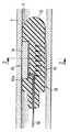
図面に擬略的に示される本発明による検査プローブは、例えば、ダクト1の内壁2、例えば、加圧水型原子力発電所の容器底内の管の内壁の超音波検査のためのものである。
The inspection probe according to the invention, which is shown schematically in the drawing, is for example for ultrasonic inspection of the
符号10によって全体的に識別された検査プローブは、ダクト1内への導入用に設計され、図面に示す実施形態では、トランシーバー型の超音波センサー11を有する。
The inspection probe, generally identified by the
ある変形例のプローブ10によれば、多センサー11を有してもよい。
According to the
センサー11は、前記センサー上に成形されたシェル12によって形成された支持体に取り付けられた支持体に取り付けられ、シェルは、一方では、本体13を有し、他方では、前記センサー11をダクト1の内壁に平らに押し付けるための手段14を有する。
The
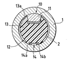
図1乃至3に示す第一実施形態によれば、ダクト1は円形の内輪郭を有し、本体13も、前記ダクトの内輪郭より僅かに小さい円形の外輪郭を有する。本体13は、センサー11の外面がシェル12の本体13の外面から非常に僅かに突出するように、センサー11を配置するための窓13aを有する。
According to the first embodiment shown in FIGS. 1 to 3, the duct 1 has a circular inner contour, and the
全ての場合に、検査プローブ10の本体13は、ダクト1の内輪郭と相補的な形状であるが、断面が前記ダクト1の内横断面より僅かに小さい外輪郭を有する。
In all cases, the
特に、図2及び図3に示すように、押付け手段14は、本体13及び本体13によって構成されたシェル12と一体的に成型され、押付け手段14は、単一部品を構成する部分を形成する。
In particular, as shown in FIGS. 2 and 3, the
概して、押付け手段は、本体に対して突出し、かつ、窓13aの方向に力を及ぼして、センサー11を前記内壁12に平らに押し付けるように、ダクト1の内壁2に当たるように(図面に示すように)設計された、前記本体13の少なくとも一つの弾性部分14を有する。
Generally, the pressing means protrudes against the body and exerts a force in the direction of the
弾性部分14がセンサー11に及ぼす押付け力は、2〜25ニュートンの間、好ましくは、5〜15ニュートンの間であるのが好ましく、前記弾性部分14は、内壁2とのセンサー11の接触部の正反対の配列で、本体13に配置される。
The pressing force exerted on the
弾性部分14は、図1に示すように、本体13の長さの少なくとも一部分に亘って延びてもよく、また、弾性部分14は前記本体13の全長に延びてもよく、さもなければ、前記本体13の長さに分布する多部分によって構成されてもよい。
The
図2に示す実施形態の一つの好適な形態によれば、弾性部分14は、それぞれ本体13と一体である二つの非剛性のウイング14a及び14bによって形成され、ウイング14a及び14bの自由端は、押付け力を各々及ぼすように内壁2に当たり、その合力は、センサー11をダクト1の内壁2に平らに押し付けるように本体13の窓13aの方に向けられる。ウイング14a及び14bは、内壁とのセンサー11の接触部の両側に、好ましくは、120°の角度で配置される。
According to one preferred form of the embodiment shown in FIG. 2, the
図3に示す一つの変形例によれば、弾性部分14は、少なくとも一つのフランジ15によって形成され、フランジは、シェル12がダクト1内へ挿入されるとき、圧縮されるようになり、そして、センサー11をダクト1の内壁2に平らに押し付けるように、本体13の窓13aに向けられた力を及ぼす。
According to one variant shown in FIG. 3, the
弾性部分14は他の形態をとってもよく、満すべき主な条件は、ダクト1の内横断面と本体13の外断面との差がプローブがダクト1の中へ挿入されるとき、弾性部分14が圧縮されるようになり、そして、センサーを内壁2に平らにさせる力をセンサー11に及ぼすように決定されなければならないことである。
The
センサー11は、シェル12の外側に通ずるワイヤ16によってデータ処理ユニットに接続され、また、ワイヤ16はプローブ10をダクト1の内側に沿って引張るためのケーブルとして役立つ。
The
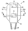
図4及び図5は、本発明によるプローブの他の用途を示し、その用途は、環状空間の内壁2を検査することである。
4 and 5 show another use of the probe according to the invention, which is to inspect the
図5に示すように、ダクト1は、前記ダクト1と同軸の内ダクト4を有し、ダクト1は、ダクト1の内壁と内ダクト4の外壁とによって構成された環状空間5を収容する。
As shown in FIG. 5, the duct 1 has an inner duct 4 that is coaxial with the duct 1, and the duct 1 accommodates an
この場合、シェル12は、環状空間5の幅より僅かに小さい厚さの実質的に台形の断面を有する本体23を有する。本体23はまた、センサー11を配置するための窓23aを有し、図4及び図5に示す例示的な実施形態では、二つのセンサー11を配置するために二つの窓23aを有する。
In this case, the
押付け手段14もまた、本体23と一体的に成型され、前記本体23の側方の縁に設置された二つの非剛性のウイング24a及び24bによって形成される。 これらのウイング24a及び24bは、本体23の長さの一部分に亘って又は全長に延びてもよい。
The pressing
環状空間5の内壁2について検査を行うために、ウイング24a及び24bは、押付け力を壁2に向けて及ぼして、センサー11を前記内壁2に平らに押し付けるように、前記環状空間5の壁6、すなわち、内ダクト4の外壁6に当たる。
In order to test the
環状空間5の外壁6について検査を行うために、ウイング24a及び24bは、押付け力を壁6に向けて及ぼして、センサー11を前記壁6に平らに押し付けるように、前記環状空間5の壁2,すなわち、外ダクト1の内壁2に当たる。
In order to inspect the
シェル12は、ポリマー、例えば、ポリウレタンで作られ、シェルは、そのポリマーに埋め込まれた金属インサートを含むのがよい。一つの変形例によれば、シェル12を、相互に相溶性の異なるポリマーで作ることができる。
The
シェル12を作るのに使用される成型技術は、例えば、ドロップ成型(drop moulding)、射出成型又はデッド成型(dead moulding)のような在来の種類のものである。
The molding technique used to make the
内壁2を検査するために、プローブ10をダクトの内側で移動させる間、内壁2の表面の歪み及びでこぼこにも拘わらず、弾性部分14は、センサー11の均一な押し付けを確保する。
While moving the
一つの変形例によれば、シェル12の本体13又は23は、種々の構成部品を位置決めするために、前記本体に収容された一つ以上の座を有してもよい。
According to one variant, the
さらに、プローブ10を、検査中のダクトに沿って移動することができる一組のプローブを構成するように、例えば、カルダン装置(cardan system)によって、さもなければ、「ドーリ車軸(dolly axle)」又は「ショックマウント(shock mount)」型の装置によって、関節連結の仕方で互いに連結された他のプローブと作動的に関連させてもよい。
In addition, the
1 ダクト
2 内壁
10 検査プローブ
11 センサー
12 シェル
13 本体
13a 窓
14 押付け手段
14a、14b ウイング
15 フランジ
16 ワイヤ
23 本体
23a 窓
24a、24b ウイング
DESCRIPTION OF SYMBOLS 1
Claims (17)
少なくとも一つのセンサーを有し、センサーが、前記センサーを内壁に平らに押し付けながら、ダクトに沿って移動されるようになっている支持体に取り付けられている、前記プローブにおいて、
支持体は、前記センサー上に成形されたシェルによって形成され、一方では、前記センサーを配置するための少なくとも一つの窓を設けた本体と、他方では、前記センサーを内壁に平らに押し付けるための、本体と一体的に成型された手段と、を有する、ことを特徴とする検査プローブ。 A probe for inspecting the inner wall of a duct,
In the probe comprising at least one sensor, wherein the sensor is attached to a support adapted to be moved along a duct while pressing the sensor flat against an inner wall,
The support is formed by a shell molded on the sensor, on the one hand a body provided with at least one window for placing the sensor and on the other hand for pressing the sensor flat against the inner wall, An inspection probe comprising: means integrally molded with the main body.
Applications Claiming Priority (1)
| Application Number | Priority Date | Filing Date | Title |
|---|---|---|---|
| FR0214542A FR2847344B1 (en) | 2002-11-20 | 2002-11-20 | PROBE FOR CONTROLLING AN INTERNAL WALL OF A CONDUIT |
Publications (2)
| Publication Number | Publication Date |
|---|---|
| JP2004264285A true JP2004264285A (en) | 2004-09-24 |
| JP4334306B2 JP4334306B2 (en) | 2009-09-30 |
Family
ID=32187777
Family Applications (1)
| Application Number | Title | Priority Date | Filing Date |
|---|---|---|---|
| JP2003319023A Expired - Fee Related JP4334306B2 (en) | 2002-11-20 | 2003-08-07 | Inspection probe for duct inner wall |
Country Status (8)
| Country | Link |
|---|---|
| US (1) | US6915715B2 (en) |
| EP (1) | EP1422520B1 (en) |
| JP (1) | JP4334306B2 (en) |
| KR (1) | KR100966535B1 (en) |
| ES (1) | ES2266755T3 (en) |
| FR (1) | FR2847344B1 (en) |
| SI (1) | SI1422520T1 (en) |
| ZA (1) | ZA200306319B (en) |
Cited By (1)
| Publication number | Priority date | Publication date | Assignee | Title |
|---|---|---|---|---|
| CN111742193A (en) * | 2018-02-19 | 2020-10-02 | 瑞纳森斯有限公司 | Sensor unit |
Families Citing this family (21)
| Publication number | Priority date | Publication date | Assignee | Title |
|---|---|---|---|---|
| US9769354B2 (en) | 2005-03-24 | 2017-09-19 | Kofax, Inc. | Systems and methods of processing scanned data |
| US9767354B2 (en) | 2009-02-10 | 2017-09-19 | Kofax, Inc. | Global geographic information retrieval, validation, and normalization |
| US9576272B2 (en) | 2009-02-10 | 2017-02-21 | Kofax, Inc. | Systems, methods and computer program products for determining document validity |
| US8519298B2 (en) * | 2010-03-25 | 2013-08-27 | Veeco Instruments, Inc. | Split laser scribe |
| KR101160662B1 (en) * | 2010-08-30 | 2012-06-28 | 한국원자력연구원 | Sensor guiding apparatus for the inspection of inner part of helical type tube |
| US10146795B2 (en) | 2012-01-12 | 2018-12-04 | Kofax, Inc. | Systems and methods for mobile image capture and processing |
| US8855375B2 (en) | 2012-01-12 | 2014-10-07 | Kofax, Inc. | Systems and methods for mobile image capture and processing |
| US9395390B2 (en) * | 2012-06-19 | 2016-07-19 | Westinghouse Electric Company Llc | Eddy current inspection probe |
| US9355312B2 (en) | 2013-03-13 | 2016-05-31 | Kofax, Inc. | Systems and methods for classifying objects in digital images captured using mobile devices |
| US9208536B2 (en) | 2013-09-27 | 2015-12-08 | Kofax, Inc. | Systems and methods for three dimensional geometric reconstruction of captured image data |
| US20140316841A1 (en) | 2013-04-23 | 2014-10-23 | Kofax, Inc. | Location-based workflows and services |
| DE202014011407U1 (en) | 2013-05-03 | 2020-04-20 | Kofax, Inc. | Systems for recognizing and classifying objects in videos captured by mobile devices |
| JP2016538783A (en) | 2013-11-15 | 2016-12-08 | コファックス, インコーポレイテッド | System and method for generating a composite image of a long document using mobile video data |
| CN103743815B (en) * | 2013-12-19 | 2016-06-22 | 安泰科技股份有限公司 | The ultrasonic wave detecting system of bend pipe composite members many bed boundarys welding quality and method |
| US9760788B2 (en) | 2014-10-30 | 2017-09-12 | Kofax, Inc. | Mobile document detection and orientation based on reference object characteristics |
| DE102015100065A1 (en) * | 2015-01-06 | 2016-07-07 | Rosen Swiss Ag | Pipe, pipe assembly, and method of measuring the thickness of a coating of a pipeline |
| US10467465B2 (en) | 2015-07-20 | 2019-11-05 | Kofax, Inc. | Range and/or polarity-based thresholding for improved data extraction |
| US10242285B2 (en) | 2015-07-20 | 2019-03-26 | Kofax, Inc. | Iterative recognition-guided thresholding and data extraction |
| US9779296B1 (en) | 2016-04-01 | 2017-10-03 | Kofax, Inc. | Content-based detection and three dimensional geometric reconstruction of objects in image and video data |
| CN106644027B (en) * | 2016-12-30 | 2019-03-05 | 中国机械工业集团有限公司 | It is a kind of for detecting the fixation device of the sensor of pipe vibration |
| US10803350B2 (en) | 2017-11-30 | 2020-10-13 | Kofax, Inc. | Object detection and image cropping using a multi-detector approach |
Family Cites Families (7)
| Publication number | Priority date | Publication date | Assignee | Title |
|---|---|---|---|---|
| JPS59149055U (en) | 1983-03-25 | 1984-10-05 | 株式会社トキメック | Ultrasonic flaw detection equipment |
| FI892088A (en) * | 1988-06-15 | 1989-12-16 | Siemens Ag | ULTRALJUDSOND FOER PROEVNING AV U-ROER I EN VAERMEVAEXLARE. |
| FR2678385B1 (en) * | 1991-06-28 | 1994-08-05 | Valdunes | METHOD AND DEVICE FOR ULTRASONIC CONTROL OF THE SURFACE CONDITION OF A BORE, ESPECIALLY THE BORE OF A RAILWAY AXLE. |
| FR2717578B1 (en) * | 1994-03-17 | 1996-06-07 | Framatome Sa | Device for non-destructive ultrasonic testing of a cylindrical wall accessible by an annular passage of small width. |
| US5533404A (en) * | 1994-12-09 | 1996-07-09 | Rjg Technologies, Inc. | Mold pressure sensor body |
| US5591912A (en) * | 1995-03-10 | 1997-01-07 | The United States Of America As Represented By The United States Department Of Energy | Method and apparatus for inspecting conduits |
| DE19617789A1 (en) * | 1996-05-05 | 1997-11-13 | Roland Thom | Inspection facility for light poles |
-
2002
- 2002-11-20 FR FR0214542A patent/FR2847344B1/en not_active Expired - Fee Related
-
2003
- 2003-08-07 SI SI200330404T patent/SI1422520T1/en unknown
- 2003-08-07 EP EP03291982A patent/EP1422520B1/en not_active Expired - Fee Related
- 2003-08-07 ES ES03291982T patent/ES2266755T3/en not_active Expired - Lifetime
- 2003-08-07 JP JP2003319023A patent/JP4334306B2/en not_active Expired - Fee Related
- 2003-08-11 US US10/637,646 patent/US6915715B2/en not_active Expired - Fee Related
- 2003-08-14 ZA ZA200306319A patent/ZA200306319B/en unknown
- 2003-08-29 KR KR1020030060083A patent/KR100966535B1/en not_active IP Right Cessation
Cited By (1)
| Publication number | Priority date | Publication date | Assignee | Title |
|---|---|---|---|---|
| CN111742193A (en) * | 2018-02-19 | 2020-10-02 | 瑞纳森斯有限公司 | Sensor unit |
Also Published As
| Publication number | Publication date |
|---|---|
| JP4334306B2 (en) | 2009-09-30 |
| EP1422520A1 (en) | 2004-05-26 |
| EP1422520B1 (en) | 2006-06-21 |
| FR2847344B1 (en) | 2005-02-25 |
| US20040093966A1 (en) | 2004-05-20 |
| US6915715B2 (en) | 2005-07-12 |
| KR100966535B1 (en) | 2010-06-29 |
| ES2266755T3 (en) | 2007-03-01 |
| KR20040044094A (en) | 2004-05-27 |
| SI1422520T1 (en) | 2006-10-31 |
| ZA200306319B (en) | 2006-12-27 |
| FR2847344A1 (en) | 2004-05-21 |
Similar Documents
| Publication | Publication Date | Title |
|---|---|---|
| JP4334306B2 (en) | Inspection probe for duct inner wall | |
| US8347724B2 (en) | Low profile ultrasound inspection scanner | |
| US4807484A (en) | Apparatus for the measurement and non-destructive material testing of laid pipelines | |
| EP2282187B1 (en) | Inspecting device including detachable probe | |
| TW201609471A (en) | Piston stroke sensor arrangement for a brake unit | |
| KR101526846B1 (en) | A lance tube diagnostic device for measuring the thickness and crack of the lance tube provided in the boilers of thermoelectric power plants | |
| KR101922111B1 (en) | Ultrasonic probe inspection apparatus | |
| WO2002082006A1 (en) | Method and instrument for measuring inside diameter of conduit | |
| JPH0254481B2 (en) | ||
| KR20200018900A (en) | Device and methodfor water wall tube inspection | |
| JP5428883B2 (en) | Roller outer surface crack diagnostic apparatus and diagnostic method | |
| EP2881700A1 (en) | Device for detecting elliptical deformation of circumferential cross section of heat-exchanger heat-transfer tube | |
| TWI767329B (en) | Inspection system for tubular members and inspection method for tubular members | |
| JP5894059B2 (en) | Eddy current flaw detector | |
| JPS60249049A (en) | Defect detecting device | |
| JPH09196713A (en) | Jig for mounting/exchanging acoustic sensor | |
| KR101885756B1 (en) | Ultrasonic sensor module structure of ultrasonic inspection device for performing non-destructive test | |
| CN205581059U (en) | Probe voussoir fixture who is fit for pipeline ultrasonic non -destructive testing | |
| RU24548U1 (en) | SENSOR CARRIER FOR IN-TUBE INSPECTION EQUIPMENT (OPTIONS) | |
| JP3180853B2 (en) | Receiving unit in remote field eddy current type flaw detector | |
| RU25593U1 (en) | SENSOR CARRIER FOR IN-TUBE INSPECTION EQUIPMENT (OPTIONS) | |
| WO2019207916A1 (en) | Pipe member flaw inspecting method, and pipe member flaw inspecting system | |
| JP2000131299A (en) | Elastic track type inspection device | |
| CN105758941A (en) | Probe wedge clamping mechanism applicable to ultrasonic nondestructive detection on pipelines | |
| KR20200002829U (en) | Phase array ultrasonic inspection system of belt type |
Legal Events
| Date | Code | Title | Description |
|---|---|---|---|
| A621 | Written request for application examination |
Free format text: JAPANESE INTERMEDIATE CODE: A621 Effective date: 20060523 |
|
| A977 | Report on retrieval |
Free format text: JAPANESE INTERMEDIATE CODE: A971007 Effective date: 20080805 |
|
| A131 | Notification of reasons for refusal |
Free format text: JAPANESE INTERMEDIATE CODE: A131 Effective date: 20081110 |
|
| A521 | Written amendment |
Free format text: JAPANESE INTERMEDIATE CODE: A523 Effective date: 20090203 |
|
| A131 | Notification of reasons for refusal |
Free format text: JAPANESE INTERMEDIATE CODE: A131 Effective date: 20090302 |
|
| A521 | Written amendment |
Free format text: JAPANESE INTERMEDIATE CODE: A523 Effective date: 20090508 |
|
| TRDD | Decision of grant or rejection written | ||
| A01 | Written decision to grant a patent or to grant a registration (utility model) |
Free format text: JAPANESE INTERMEDIATE CODE: A01 Effective date: 20090601 |
|
| A01 | Written decision to grant a patent or to grant a registration (utility model) |
Free format text: JAPANESE INTERMEDIATE CODE: A01 |
|
| A61 | First payment of annual fees (during grant procedure) |
Free format text: JAPANESE INTERMEDIATE CODE: A61 Effective date: 20090623 |
|
| FPAY | Renewal fee payment (event date is renewal date of database) |
Free format text: PAYMENT UNTIL: 20120703 Year of fee payment: 3 |
|
| R150 | Certificate of patent or registration of utility model |
Free format text: JAPANESE INTERMEDIATE CODE: R150 |
|
| LAPS | Cancellation because of no payment of annual fees |