JP2004262445A - Air vent structure of aeration device - Google Patents
Air vent structure of aeration device Download PDFInfo
- Publication number
- JP2004262445A JP2004262445A JP2004058617A JP2004058617A JP2004262445A JP 2004262445 A JP2004262445 A JP 2004262445A JP 2004058617 A JP2004058617 A JP 2004058617A JP 2004058617 A JP2004058617 A JP 2004058617A JP 2004262445 A JP2004262445 A JP 2004262445A
- Authority
- JP
- Japan
- Prior art keywords
- air
- circulation chamber
- perforated wall
- ventilation structure
- housing
- Prior art date
- Legal status (The legal status is an assumption and is not a legal conclusion. Google has not performed a legal analysis and makes no representation as to the accuracy of the status listed.)
- Pending
Links
- 238000005273 aeration Methods 0.000 title abstract 3
- 238000009423 ventilation Methods 0.000 claims description 37
- 238000011144 upstream manufacturing Methods 0.000 claims description 5
- 230000002093 peripheral effect Effects 0.000 claims description 2
- 238000010276 construction Methods 0.000 claims 1
- 230000004941 influx Effects 0.000 abstract 3
- 230000000694 effects Effects 0.000 description 7
- 230000000903 blocking effect Effects 0.000 description 3
- 230000015572 biosynthetic process Effects 0.000 description 2
- 238000009792 diffusion process Methods 0.000 description 2
- 238000013022 venting Methods 0.000 description 2
- 238000000576 coating method Methods 0.000 description 1
Images


Classifications
-
- B—PERFORMING OPERATIONS; TRANSPORTING
- B60—VEHICLES IN GENERAL
- B60H—ARRANGEMENTS OF HEATING, COOLING, VENTILATING OR OTHER AIR-TREATING DEVICES SPECIALLY ADAPTED FOR PASSENGER OR GOODS SPACES OF VEHICLES
- B60H1/00—Heating, cooling or ventilating [HVAC] devices
- B60H1/34—Nozzles; Air-diffusers
- B60H1/3414—Nozzles; Air-diffusers with means for adjusting the air stream direction
-
- E—FIXED CONSTRUCTIONS
- E04—BUILDING
- E04F—FINISHING WORK ON BUILDINGS, e.g. STAIRS, FLOORS
- E04F15/00—Flooring
- E04F15/18—Separately-laid insulating layers; Other additional insulating measures; Floating floors
- E04F15/20—Separately-laid insulating layers; Other additional insulating measures; Floating floors for sound insulation
- E04F15/206—Layered panels for sound insulation
-
- E—FIXED CONSTRUCTIONS
- E04—BUILDING
- E04B—GENERAL BUILDING CONSTRUCTIONS; WALLS, e.g. PARTITIONS; ROOFS; FLOORS; CEILINGS; INSULATION OR OTHER PROTECTION OF BUILDINGS
- E04B1/00—Constructions in general; Structures which are not restricted either to walls, e.g. partitions, or floors or ceilings or roofs
- E04B1/62—Insulation or other protection; Elements or use of specified material therefor
- E04B1/74—Heat, sound or noise insulation, absorption, or reflection; Other building methods affording favourable thermal or acoustical conditions, e.g. accumulating of heat within walls
- E04B1/88—Insulating elements for both heat and sound
- E04B1/90—Insulating elements for both heat and sound slab-shaped
-
- E—FIXED CONSTRUCTIONS
- E04—BUILDING
- E04C—STRUCTURAL ELEMENTS; BUILDING MATERIALS
- E04C2/00—Building elements of relatively thin form for the construction of parts of buildings, e.g. sheet materials, slabs, or panels
- E04C2/30—Building elements of relatively thin form for the construction of parts of buildings, e.g. sheet materials, slabs, or panels characterised by the shape or structure
- E04C2/34—Building elements of relatively thin form for the construction of parts of buildings, e.g. sheet materials, slabs, or panels characterised by the shape or structure composed of two or more spaced sheet-like parts
- E04C2/36—Building elements of relatively thin form for the construction of parts of buildings, e.g. sheet materials, slabs, or panels characterised by the shape or structure composed of two or more spaced sheet-like parts spaced apart by transversely-placed strip material, e.g. honeycomb panels
- E04C2/365—Building elements of relatively thin form for the construction of parts of buildings, e.g. sheet materials, slabs, or panels characterised by the shape or structure composed of two or more spaced sheet-like parts spaced apart by transversely-placed strip material, e.g. honeycomb panels by honeycomb structures
Abstract
Description
本発明は車両における通気装置のための空気通気構造に関する。 The present invention relates to an air ventilation structure for a ventilation device in a vehicle.
既知の通気装置においては、空気は通常調整可能で出口表面の近傍にある羽根又は回転かごの如き空気ガイド素子を有する流出通気構造を通って流出する。出口表面の外観はガイド素子の位置により特徴づけられ、一様ではない。格子等による出口表面でのガイド素子の被覆は不可能である。その理由は、このような被覆により方位効果が失われるからである。 In known venting devices, air exits through an outflow ventilation structure that is usually adjustable and has air guide elements such as vanes or rotating cages near the outlet surface. The appearance of the outlet surface is characterized by the position of the guide element and is not uniform. It is not possible to coat the guide element on the exit surface with a grid or the like. The reason is that such coatings lose the orientation effect.
空気通気構造はまた拡散効果を有するものも知られる。かかる空気通気構造においては、出口表面は一様な外観を有することができるが、方位効果を得ることは不可能であり、そのため、拡散効果を有する流出装置は、空気分布の両方のモードが設けられる場合は、方位効果を備えたものに加えて、車両内に設置される。 Air vent structures are also known to have a diffusion effect. In such an air ventilation structure, the outlet surface can have a uniform appearance, but it is not possible to obtain an azimuthal effect, so that the outflow device with diffusion effect is provided with both modes of air distribution. If installed, it will be installed in the vehicle in addition to the one with the azimuth effect.
下記特許文献1は軸線のまわりで回転でき、通路を具備した空気出口素子を有する、車両の内部のための空気流出装置を記載している。空気出口素子の位置に応じて、空気は拡散される又は方向付けられる態様で乗員コンパートメント内へ送給される。出口表面はこの空気出口素子の位置に応じてその外観が変わる。 US Pat. No. 5,077,064 describes an air outlet device for the interior of a vehicle that has an air outlet element rotatable about an axis and having a passage. Depending on the position of the air outlet element, air is delivered into the occupant compartment in a diffused or directed manner. The outlet surface changes its appearance depending on the position of the air outlet element.
下記特許文献2は乗員コンパートメント内へ空気を送給する装置を開示しており、この装置は2つの空気流出開口を具備する。ここでは、一方の空気流出開口は直接通気のために役立ち、第2の開口は拡散空気送給のために役立つ。 U.S. Pat. No. 5,077,064 discloses a device for delivering air into an occupant compartment, which device has two air outlet openings. Here, one air outlet opening serves for direct ventilation and the second serves for diffused air delivery.
本発明は、その設定に関係なく、出口表面の一様な外観を有し、任意の空気分布モードを許容する空気通気構造を提供することを目的とする。 An object of the present invention is to provide an air ventilation structure that has a uniform appearance of an outlet surface and allows an arbitrary air distribution mode regardless of its setting.
より詳しくは、本発明は実質的にたる形状(即ち丸みを帯びた形状)を有するハウジングにより画定される空気循環室を備えた、車両における通気装置のための空気通気構造を提供する。流入ダクトは循環室のハウジングに接続され、その中へ開口している。ハウジングは孔付き壁領域を有する。使用において、空気ストリームは流入ダクトを通って循環室へ入り、空気循環室を通って循環し、孔付き壁領域を通って流出する。空気通気構造は更に流入ダクトの軸方向に対して横断方向に空気ストリームを偏向させるように位置する可動の空気偏向部材を有する。 More specifically, the present invention provides an air ventilation structure for a ventilation system in a vehicle, comprising an air circulation chamber defined by a housing having a substantially barrel shape (ie, a rounded shape). The inlet duct is connected to the housing of the circulation chamber and opens into it. The housing has a perforated wall area. In use, the air stream enters the circulation chamber through the inlet duct, circulates through the air circulation chamber, and exits through the perforated wall area. The air venting structure further includes a movable air deflecting member positioned to deflect the air stream transverse to an axial direction of the inlet duct.
たる形状の循環室及び流入する空気ストリームの軸方向に対して横断方向に空気ストリームを偏向させる可動の空気偏向部材の配列は、空気流の一部を循環室の内部で回転させる。可動の空気偏向部材の使用により、循環室内での部分的な空気流の回転方向を所望通りに変更できる。回転の結果として、出口表面を形成する孔付き壁領域に平行な速度成分が形成される。出現する空気はこれに対応して偏向される。換言すれば、たる形状の循環室のある領域において、空気流は内側の壁に沿って進み、循環室から出るときにその方向を維持する。カバー格子によってさえ、この方向は影響されない。 An array of barrel-shaped circulation chambers and a movable air deflecting member that deflects the air stream transversely to the axial direction of the incoming air stream causes a portion of the air flow to rotate within the circulation chamber. By using a movable air deflection member, the direction of rotation of the partial airflow in the circulation chamber can be changed as desired. As a result of the rotation, a velocity component parallel to the perforated wall area forming the outlet surface is formed. The emerging air is correspondingly deflected. In other words, in some areas of the barrel-shaped circulation chamber, the air flow travels along the inner wall and maintains its direction as it leaves the circulation chamber. Even with a cover grid, this direction is unaffected.
1つの実施の形態においては、空気偏向部材は流入ダクトの端部において孔付き壁領域に対向して位置し、ほぼボール状の本体を有する。これは流入ダクトの端部における環状の軸受セット内に回転自在に収容される。空気偏向部材はボール状の本体を通って直径方向に延びる円筒形状のチャンネル区分を画定する。 In one embodiment, the air deflecting member is located at the end of the inlet duct opposite the perforated wall region and has a generally ball-shaped body. It is rotatably housed in an annular bearing set at the end of the inlet duct. The air deflecting member defines a cylindrical channel section that extends diametrically through the ball-shaped body.
このような空気偏向部材により、流入する空気ストリームをハウジングの内部に沿って直接案内することができ、部分的な空気ストリームの回転を生じさせる。空気偏向部材は孔付き壁領域に対向して位置し、空気ストリームを任意の方向でハウジングの内側に沿って案内できる。 Such an air deflecting member allows the incoming air stream to be guided directly along the interior of the housing, causing a partial air stream rotation. The air deflecting member is located opposite the perforated wall area and can guide the air stream in any direction along the inside of the housing.
好ましい実施の形態においては、空気ガイドが孔付き壁領域に隣接して空気循環室内に配置される。循環室の内部に位置するこの空気ガイドにより、回転効果により既に生じた空気流の偏向を更に強めることができる。この空気ガイドは、微細なメッシュのカバー格子のための支持板として同時に使用できるような方法で設計することができる。空気ガイドは孔付き壁領域の上流側で空気循環室内に枢着された一組の直線状のバッフル部材を有することができる。これらのバッフル部材の設定は方向付けられた空気流を支持できるか又は空気ストリームを拡散することができる。 In a preferred embodiment, an air guide is located in the air circulation chamber adjacent to the perforated wall area. With this air guide located inside the circulation chamber, the deflection of the air flow already caused by the rotation effect can be further increased. The air guide can be designed in such a way that it can simultaneously be used as a support plate for a fine mesh cover grid. The air guide may have a set of straight baffle members pivotally mounted in the air circulation chamber upstream of the perforated wall area. The setting of these baffle members can support a directed air flow or diffuse the air stream.
別の実施の形態においては、空気偏向部材はシールド部材からなる。このシールド部材は空気循環室内で軸方向に移動することができる。流入ダクトを閉じる遮断位置へシールド部材を運動させることもできる。このようにして、流出する空気の方向の変化及び空気ストリームの完全な中断をたった1つの空気偏向部材即ちシールド部材で達成することができる。 In another embodiment, the air deflecting member comprises a shielding member. This shield member can move axially in the air circulation chamber. The shield member can also be moved to a blocking position that closes the inflow duct. In this way, a change in the direction of the outflowing air and a complete interruption of the air stream can be achieved with only one air deflecting or shielding member.
好ましい実施の形態においては、シールド部材は環状のディフューザ構造体と相互作用する。ここでは、ディフューザ構造体及びシールド部材は空気循環室内で可動である。互いに関するシールド部材及びディフューザ構造体の位置に応じて、同じ空気通気構造が乗員コンパートメントの拡散された又は方向付けられた通気を達成できる。覆われた位置においては、シールド部材はディフューザ構造体を覆う。そこでは、ディフューザ構造体はシールド部材により方向付けられた空気流の偏向に影響を与えない。ディフューザ構造体は循環室の孔付き壁領域の近傍に位置する場合にのみ有効である。その理由は、この場合にのみ、空気がそこを通って流れるからである。 In a preferred embodiment, the shield member interacts with the annular diffuser structure. Here, the diffuser structure and the shield member are movable in the air circulation chamber. Depending on the position of the shield member and the diffuser structure relative to each other, the same air ventilation structure can achieve diffused or directed ventilation of the occupant compartment. In the covered position, the shield member covers the diffuser structure. There, the diffuser structure does not affect the deflection of the air flow directed by the shield member. The diffuser structure is only effective when located near the perforated wall area of the circulation chamber. The reason is that only in this case is the air flowing through it.
好ましい実施の形態では、孔付き壁領域は微細なメッシュ格子により形成される。この構成は空気通気構造の可視の前部に一様な外観を与える。 In a preferred embodiment, the perforated wall region is formed by a fine mesh grid. This arrangement provides a uniform appearance to the visible front of the air vent structure.
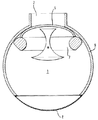
図1はそのハウジング9を備えたたる形状(丸みを帯びた形状)の循環室1及び流入ダクト2の断面図を示す。孔付き壁領域3は微細なメッシュ格子8により形成される。流入ダクト2はハウジング9に接続し、孔付き壁領域3に対向して循環室1に開口している。空気偏向部材4はほぼボール状の本体を有する。この部材は流入ダクト2の端部において環状の軸受座内に回転自在に収容される。空気偏向部材4はボール状の本体を通って直径方向に延びる円筒形状のチャンネル区分を画定する。空気循環室1へ入るためには、空気ストリームはこのチャンネル区分を通らねばならない。空気偏向部材4のボール状の本体の回転位置を調整することにより、空気ストリームが偏向される。可動の空気偏向部材4の図示の位置においては、使用時に流入ダクトを通って流入する矢印10で示す流入空気はハウジング9の内表面に沿って左方へ進む。従って、空気循環室1を通って循環する空気ストリームは可動の空気偏向部材4により流入ダクト2の軸方向に対して横断方向に偏向される。次いで、空気ストリームはハウジング9の壁に対して向けられ、そこで、壁の湾曲に従って変向される。空気ストリームの一部はハウジング9の壁に沿って延び、一方、空気流の別な部分は室1内で循環する傾向を有する。変向のため、孔付き壁領域3を通って流出する空気は偏向部材4を調整した方向とは反対の方向における成分を有する。空気ガイド5は孔付き壁領域に平行な速度成分の形成を強める。ガイドは孔付き壁領域3に隣接して空気循環室1内に配置され、孔付き壁領域3から離間した連続的な壁を有する。この壁は孔付き壁領域3に平行に延びる。
FIG. 1 is a sectional view of a barrel (rounded shape)
図2は図1のものに関して僅かに修正された実施の形態を示す。ここでは、空気ガイド5は孔付き壁領域3の上流側の固定の位置に一組の湾曲したバッフル部材11を有する。循環室1内の空気流の一部は可動の空気偏向部材4の位置により決定される円形運動を与えられる。図1の実施の形態と比較して、矢印10で示す図2の空気流は一層少ない程度しか邪魔されない。湾曲したバッフル部材11は、これらの部材が空気循環室1から出現する空気の偏向を強め、室1内の部分的な回転する流れを促進するような方法で、配置される。
FIG. 2 shows a slightly modified embodiment with respect to that of FIG. Here, the air guide 5 has a set of
図3に示す別の実施の形態においては、空気循環室1の内部で孔付き壁領域3に隣接して配置された空気ガイド5は孔付き壁領域3の上流側で空気循環室1内に枢着された一組の直線状のバッフル部材12を有する。図3に示すような空気偏向部材4及び直線状のバッフル部材12の位置により、拡散空気流出流が発生する。循環室1の内部での空気流の循環を図1、2に示すように空気偏向部材4を仕向けることにより得る場合は、この方向付けされた空気流出流は直線状のバッフル部材12を適当に位置決めすることによりさらに強めることができる。
In another embodiment shown in FIG. 3, an air guide 5 arranged inside the
図4は空気循環室1と、シールド部材6と、ディフューザ構造体7と、微細なメッシュ格子8とを備えた別の実施の形態の分解部品図を示す。空気循環室1の内部に配置されたシールド部材6はたる形状の循環室1の内部で空気循環を発生させる役目を行う。シールド部材6は凸状に湾曲した面を有する。ここでは、空気流はシールド部材6と空気循環室1のハウジング9との間で案内される。空気循環室の内部に配置されたディフューザ構造体7はシールド部材6により覆われることができるか、又は拡散空気流出流の形成が可能になるように空気流内へ移動することができる。微細なメッシュの格子8は空気通気構造を覆う役目を果たし、一様な外観を提供する。
FIG. 4 is an exploded view of another embodiment including the
図5、6は図4の分解部品図に対応する空気通気構造の断面図をそれぞれ示すが、ディフューザ構造体は示さない。たる形状の空気循環室1はほぼ球状形状のハウジング9により取り囲まれる。流入ダクト2を介して、空気は空気循環室1へ入る。シールド部材6の凸状に湾曲した面は入来する空気ストリームに曝される。孔付き壁領域は微細なメッシュ格子8により形成される。図5において、円形形状のシールド部材6は軸方向に対して横断方向に運動できるように装着される。図示の位置においては、空気流は右手側のみでシールド部材6を通過することができ、空気循環室1のハウジング壁9に沿って位置するようになる。格子8を通過した後でさえ、空気流はその方向を維持する。
5 and 6 show cross-sectional views of the air ventilation structure corresponding to the exploded view of FIG. 4, respectively, but do not show the diffuser structure. The barrel-shaped
図6に示すように、シールド部材6は軸方向に垂直な枢軸のまわりで枢動するように装着することができる。ここでは、また、空気流10は循環室1のハウジング9の内壁とシールド部材6との間を通る。空気流は微細なメッシュ格子8を通過し、方向付けされた態様で空気通気構造を去る。
As shown in FIG. 6, the
図7、8を参照してディフューザ構造体7の作動モードを説明する。これら両方の図は流入ダクト2、シールド部材6及びディフューザ構造体7を備えた空気循環室1を示す。環状のディフューザ構造体7は外側リングと、母線を回転して形成される形状の凹状の周辺表面を備えた中央の偏向本体とを有する。図7において、シールド部材6及びディフューザ構造体7は互いにじかに隣接する。従って、シールド部材はディフューザ構造体を覆う覆い位置にある。流入する空気10はシールド部材6により偏向され、ディフューザ構造体7の外部のまわりで案内される。ディフューザ構造体7は空気流に効果を与えない。微細なメッシュ格子8により形成された孔付き壁領域ははっきりとした空気ジェットとなって出る空気流の束を形成する。空気通気構造から流れる空気は軸方向に方向付けられる。微細なメッシュ格子8は空気流の方向に影響を与えない。
The operation mode of the
ディフューザ構造体7は孔付き壁領域に対して進退するように空気循環室1内で可動である。図8において、ディフューザ構造体7は孔付き壁領域の方向に移動される。孔付き壁領域に対向するディフューザ構造体7の中央の偏向本体の端面は孔付き壁領域の中央部分を覆うようになっており、ここでは、微細なメッシュ格子8に接触するように移動される。シールド部材6はもはやディフューザ構造体7を覆わない。このとき、シールド部材6を通過して流れる空気10はディフューザ構造体7を通って流れる。
The
図9において、シールド部材6及びディフューザ構造体7は遮断位置へ移動される。シールド部材6は流入ダクト2をハウジング9に接続するハウジング9の開口に対して進退するように空気循環室1内で軸方向に運動できる。シールド部材6は、更なる空気が空気循環室1へ入らないように、流入ダクト2を閉じる。この遮断位置で、本発明に係る空気通気構造を通る空気流を完全に阻止することができる。
In FIG. 9, the
1 空気循環室
2 流入ダクト
3 孔付き壁領域
4 空気偏向部材
5 空気ガイド
6 シールド部材
7 ディフューザ構造体
8 微細なメッシュ格子
9 ハウジング
11、12 バッフル部材
DESCRIPTION OF
Claims (16)
実質上たる形状を有するハウジングにより画定される空気循環室(1)と、
上記ハウジングに接続され、上記循環室(1)内へ開口する流入ダクト(2)と、
を有し、上記ハウジングが孔付き壁領域(3)を有し、使用時に、空気ストリームが上記流入ダクト(2)を通って上記循環室(1)へ入り、当該空気循環室を通って循環し、上記孔付き壁領域(3)を通って流出するようになっており、
さらに上記流入ダクト(2)の軸方向に対して横断方向に空気ストリームを偏向させるように位置する可動の空気偏向部材(4;6)を有する、
ことを特徴とする空気通気構造。 In an air ventilation structure for a ventilation device in a vehicle,
An air circulation chamber (1) defined by a housing having a substantially barrel shape;
An inflow duct (2) connected to the housing and opening into the circulation chamber (1);
Wherein the housing has a perforated wall area (3), and in use an air stream enters the circulation chamber (1) through the inlet duct (2) and circulates through the air circulation chamber And flows out through the perforated wall region (3).
Further comprising a movable air deflecting member (4; 6) positioned to deflect the air stream transversely to the axial direction of said inlet duct (2);
An air ventilation structure characterized by the following.
Applications Claiming Priority (1)
| Application Number | Priority Date | Filing Date | Title |
|---|---|---|---|
| DE20303401 | 2003-03-03 |
Publications (1)
| Publication Number | Publication Date |
|---|---|
| JP2004262445A true JP2004262445A (en) | 2004-09-24 |
Family
ID=32798213
Family Applications (1)
| Application Number | Title | Priority Date | Filing Date |
|---|---|---|---|
| JP2004058617A Pending JP2004262445A (en) | 2003-03-03 | 2004-03-03 | Air vent structure of aeration device |
Country Status (4)
| Country | Link |
|---|---|
| US (1) | US7201650B2 (en) |
| EP (1) | EP1454780A3 (en) |
| JP (1) | JP2004262445A (en) |
| KR (1) | KR20040078069A (en) |
Cited By (1)
| Publication number | Priority date | Publication date | Assignee | Title |
|---|---|---|---|---|
| JP2008037376A (en) * | 2006-08-09 | 2008-02-21 | Toyota Motor Corp | Air conditioning register |
Families Citing this family (32)
| Publication number | Priority date | Publication date | Assignee | Title |
|---|---|---|---|---|
| DE60320687T2 (en) * | 2002-03-15 | 2009-07-02 | Trw Automotive Electronics & Components Gmbh | Ventilation nozzle for ventilation systems |
| US20120195749A1 (en) | 2004-03-15 | 2012-08-02 | Airius Ip Holdings, Llc | Columnar air moving devices, systems and methods |
| FR2872260B1 (en) * | 2004-06-24 | 2008-10-03 | Faurecia Interieur Ind Snc | AERATEUR |
| JP4287848B2 (en) * | 2005-07-29 | 2009-07-01 | 株式会社ケーヒン | Air conditioner for vehicles |
| JP4670749B2 (en) * | 2006-06-20 | 2011-04-13 | トヨタ自動車株式会社 | Air conditioner outlet structure |
| DE102006062178B3 (en) * | 2006-12-22 | 2008-02-28 | Faurecia Innenraum Systeme Gmbh | Air outflow device has nozzle housing, air inlet opening, air outlet opening and air guiding element, where air guiding element is arranged with pointed side towards air outlet opening |
| DE102007019602B3 (en) * | 2007-04-24 | 2008-06-26 | Faurecia Innenraum Systeme Gmbh | Air discharging device for use in e.g. railcar, has laminar element arranged at end of another laminar element, and nozzle housing and air guidance element formed for producing Coanda effects so that air flow is discharged from opening |
| US8616842B2 (en) * | 2009-03-30 | 2013-12-31 | Airius Ip Holdings, Llc | Columnar air moving devices, systems and method |
| US9459020B2 (en) | 2008-05-30 | 2016-10-04 | Airius Ip Holdings, Llc | Columnar air moving devices, systems and methods |
| US9151295B2 (en) | 2008-05-30 | 2015-10-06 | Airius Ip Holdings, Llc | Columnar air moving devices, systems and methods |
| WO2012174155A1 (en) | 2011-06-15 | 2012-12-20 | Airius Ip Holdings, Llc | Columnar air moving devices, systems and methods |
| USD698916S1 (en) | 2012-05-15 | 2014-02-04 | Airius Ip Holdings, Llc | Air moving device |
| CA2875339A1 (en) | 2013-12-19 | 2015-06-19 | Airius Ip Holdings, Llc | Columnar air moving devices, systems and methods |
| CA2875347C (en) | 2013-12-19 | 2022-04-19 | Airius Ip Holdings, Llc | Columnar air moving devices, systems and methods |
| CA2953226C (en) | 2014-06-06 | 2022-11-15 | Airius Ip Holdings, Llc | Columnar air moving devices, systems and methods |
| US9963015B1 (en) | 2015-01-16 | 2018-05-08 | Ultra Manufacturing Limited | Vent outlet assembly |
| JP6368328B2 (en) * | 2016-02-10 | 2018-08-01 | 株式会社豊田自動織機 | Register and vehicle |
| USD805176S1 (en) | 2016-05-06 | 2017-12-12 | Airius Ip Holdings, Llc | Air moving device |
| USD820967S1 (en) | 2016-05-06 | 2018-06-19 | Airius Ip Holdings Llc | Air moving device |
| US10487852B2 (en) | 2016-06-24 | 2019-11-26 | Airius Ip Holdings, Llc | Air moving device |
| DE102016225128A1 (en) * | 2016-12-15 | 2018-06-21 | Bayerische Motoren Werke Aktiengesellschaft | Air vents for a motor vehicle and motor vehicle equipped therewith |
| USD886275S1 (en) | 2017-01-26 | 2020-06-02 | Airius Ip Holdings, Llc | Air moving device |
| DE202017101922U1 (en) * | 2017-03-31 | 2017-05-26 | Reamotion Gmbh | Device for heating and / or cooking food |
| KR102141273B1 (en) | 2017-05-24 | 2020-08-04 | 주식회사 엘지화학 | A baffle apparatus for improving a flow deviation |
| USD885550S1 (en) | 2017-07-31 | 2020-05-26 | Airius Ip Holdings, Llc | Air moving device |
| FR3086585B1 (en) * | 2018-09-27 | 2020-09-04 | Valeo Systemes Thermiques | AUTOMOTIVE VEHICLE VENTILATOR, DEVICE AND METHOD FOR THERMAL MANAGEMENT USING SUCH A MOTOR VEHICLE VENTILATOR |
| CN109835143B (en) * | 2019-01-07 | 2020-07-28 | 南京塔塔汽车零部件系统有限公司 | Air outlet method for realizing no front blade of automobile air conditioner |
| USD887541S1 (en) | 2019-03-21 | 2020-06-16 | Airius Ip Holdings, Llc | Air moving device |
| AU2020257205A1 (en) | 2019-04-17 | 2021-11-04 | Airius Ip Holdings, Llc | Air moving device with bypass intake |
| DE102019118239A1 (en) | 2019-07-05 | 2021-01-07 | Fischer Automotive Systems Gmbh & Co. Kg | Air vents |
| DE102019118243A1 (en) * | 2019-07-05 | 2021-01-07 | Fischer Automotive Systems Gmbh & Co. Kg | Air vents |
| CN113212117B (en) * | 2021-06-24 | 2022-08-05 | 宁波均胜群英汽车系统股份有限公司 | Three-channel air outlet of automobile air conditioner |
Family Cites Families (11)
| Publication number | Priority date | Publication date | Assignee | Title |
|---|---|---|---|---|
| DE2716993A1 (en) * | 1977-04-18 | 1978-10-26 | Schmid Reuter Ingenieurgesells | DEVICE FOR VENTILATION AND / OR AIR CONDITIONING OF ROOMS |
| US4437392A (en) | 1980-12-17 | 1984-03-20 | Bowles Fluidics Corporation | Sweeping air stream apparatus and method |
| US4637298A (en) * | 1984-05-03 | 1987-01-20 | Toyota Jidosha Kabushiki Kaisha | Windshield defroster |
| US5297989A (en) * | 1993-01-13 | 1994-03-29 | Bowles Fluidics Corporation | Nozzle for discharging air and method |
| ATE174556T1 (en) * | 1992-03-17 | 1999-01-15 | Bowles Fluidics Corp | NOZZLE AND VENTILATION METHOD |
| GB2292797B (en) | 1994-09-02 | 1998-07-08 | Rover Group | An air vent for a vehicle interior |
| DE19508983C1 (en) | 1995-03-13 | 1996-02-15 | Daimler Benz Ag | Device for diffuse ventilation of vehicle interior |
| US5816907A (en) * | 1997-02-25 | 1998-10-06 | Bowles Fluidics Corporation | Vehicle air outlet with combined flow straightener and shutoff door |
| DE19721831B4 (en) | 1997-05-24 | 2007-05-24 | Reum Gmbh & Co. Betriebs Kg | air vents |
| DE10011932C1 (en) | 2000-03-11 | 2001-03-08 | Daimler Chrysler Ag | Ventilation device for automobile passenger compartment has direct and diffuse air flow openings controlled by respective blocking elements to provide required air distribution |
| FR2815295B1 (en) | 2000-10-17 | 2003-04-18 | Visteon Systemes Interieurs | DEVICE FOR BROADCASTING AN AIR FLOW WITHIN A MOTOR VEHICLE INTERIOR |
-
2004
- 2004-02-26 EP EP04004436A patent/EP1454780A3/en not_active Withdrawn
- 2004-03-02 US US10/791,206 patent/US7201650B2/en not_active Expired - Fee Related
- 2004-03-03 KR KR1020040014287A patent/KR20040078069A/en not_active Application Discontinuation
- 2004-03-03 JP JP2004058617A patent/JP2004262445A/en active Pending
Cited By (1)
| Publication number | Priority date | Publication date | Assignee | Title |
|---|---|---|---|---|
| JP2008037376A (en) * | 2006-08-09 | 2008-02-21 | Toyota Motor Corp | Air conditioning register |
Also Published As
| Publication number | Publication date |
|---|---|
| US20040224625A1 (en) | 2004-11-11 |
| US7201650B2 (en) | 2007-04-10 |
| KR20040078069A (en) | 2004-09-08 |
| EP1454780A2 (en) | 2004-09-08 |
| EP1454780A3 (en) | 2006-02-15 |
Similar Documents
| Publication | Publication Date | Title |
|---|---|---|
| JP2004262445A (en) | Air vent structure of aeration device | |
| US6364760B1 (en) | Air outlet system | |
| CN101622144B (en) | Air outlet having a swirling flow, and conventional flow | |
| KR20030074455A (en) | Air vent for ventilation systems | |
| KR102499701B1 (en) | Nozzle for fan assembly | |
| RU2518092C2 (en) | Air outlet device | |
| US5725159A (en) | Air directing device for a hair dryer | |
| KR20110052472A (en) | Vehicle ventilation system | |
| KR102499694B1 (en) | Nozzle for fan assembly | |
| KR102269827B1 (en) | Air vent for vehicle | |
| CN211174828U (en) | Nozzle for fan assembly and fan assembly | |
| CN111791676A (en) | Ventilation device with improved directionality comprising a mesh panel | |
| US20210046805A1 (en) | Fluid discharge device | |
| JP2005538899A (en) | Air inflow | |
| CN109996999A (en) | The adjustable air purifier of wind direction | |
| US20020142715A1 (en) | Air outlet system | |
| US11554632B2 (en) | Air vent for introducing air into a motor vehicle interior | |
| EP3632725A1 (en) | Air diffuser for a vehicle | |
| US20060116063A1 (en) | Outlet device for the interior of a vehicle | |
| EP1582749B1 (en) | Air intake | |
| US20200290432A1 (en) | Air vents for the interior of a motor vehicle | |
| KR900001876B1 (en) | Fluid deflecting assembly | |
| JP4398217B2 (en) | Air outlet device | |
| US11280517B1 (en) | Air vent with rotating control elements and a central element defining channels and method of controlloing air flow via same | |
| CN113631400A (en) | Vehicle ventilation assembly |
Legal Events
| Date | Code | Title | Description |
|---|---|---|---|
| A521 | Request for written amendment filed |
Free format text: JAPANESE INTERMEDIATE CODE: A821 Effective date: 20040519 |
|
| A621 | Written request for application examination |
Free format text: JAPANESE INTERMEDIATE CODE: A621 Effective date: 20061212 |
|
| A131 | Notification of reasons for refusal |
Free format text: JAPANESE INTERMEDIATE CODE: A131 Effective date: 20080820 |
|
| A02 | Decision of refusal |
Free format text: JAPANESE INTERMEDIATE CODE: A02 Effective date: 20090202 |