JP2004259657A - Lighting apparatus state monitor system - Google Patents
Lighting apparatus state monitor system Download PDFInfo
- Publication number
- JP2004259657A JP2004259657A JP2003051153A JP2003051153A JP2004259657A JP 2004259657 A JP2004259657 A JP 2004259657A JP 2003051153 A JP2003051153 A JP 2003051153A JP 2003051153 A JP2003051153 A JP 2003051153A JP 2004259657 A JP2004259657 A JP 2004259657A
- Authority
- JP
- Japan
- Prior art keywords
- infrared signal
- lighting
- lighting fixture
- unit
- dimming
- Prior art date
- Legal status (The legal status is an assumption and is not a legal conclusion. Google has not performed a legal analysis and makes no representation as to the accuracy of the status listed.)
- Pending
Links
Images


Classifications
-
- Y—GENERAL TAGGING OF NEW TECHNOLOGICAL DEVELOPMENTS; GENERAL TAGGING OF CROSS-SECTIONAL TECHNOLOGIES SPANNING OVER SEVERAL SECTIONS OF THE IPC; TECHNICAL SUBJECTS COVERED BY FORMER USPC CROSS-REFERENCE ART COLLECTIONS [XRACs] AND DIGESTS
- Y02—TECHNOLOGIES OR APPLICATIONS FOR MITIGATION OR ADAPTATION AGAINST CLIMATE CHANGE
- Y02B—CLIMATE CHANGE MITIGATION TECHNOLOGIES RELATED TO BUILDINGS, e.g. HOUSING, HOUSE APPLIANCES OR RELATED END-USER APPLICATIONS
- Y02B20/00—Energy efficient lighting technologies, e.g. halogen lamps or gas discharge lamps
- Y02B20/40—Control techniques providing energy savings, e.g. smart controller or presence detection
Abstract
Description
【0001】
【発明の属する技術分野】
本発明は例えば複数の照明装置の消費電力量等の調光状態を監視、記録、制御及び他設備への情報伝達を可能とする照明器具状態監視システムに関するものである。
【0002】
【従来の技術】
従来の電力量計は、テレビ、冷蔵庫、照明器具等の各種電気機器が接続された屋内の電灯線と屋外の送電線から延びる電力線との間に設けられた筐体に各種電気機器の電力使用量を計測する電力量計測器を内蔵するようにして構成されている(例えば、特許文献1参照)。
【0003】
【特許文献1】
特開2001−28093号公報(第2頁、第1図)
【0004】
【発明が解決しようとする課題】
従来の電力量計は、屋内の電灯線と屋外の送電線から延びる電力線との間に設けられた筐体に各種電気機器の電力使用量を計測する電力量計測器を内蔵するようにして構成されているから、電力量計の設置には、電気工事が必要となり、電力量計の設置場所も電灯線に対しての作業ができ、メンテナンスがし易い場所等の制約があるという問題点があった。
【0005】
本発明は、このような問題点を解決するためになされたものであり、照明器具の電力量をリアルタイムに監視することができ、照明器具の電力量を計測する場合にも電気工事を不要とし、設置場所等の制約をなくし、よりユーザに使い易い照明器具状態監視システムを得ることを目的とする。
【0006】
【課題を解決するための手段】
本発明に係る照明器具状態監視システムは、調光制御情報を赤外線信号で送信する親機と、親機から受信した赤外線信号の調光制御情報に基づいてランプに対して調光制御を行う機能及び必要に応じて該赤外線信号を送信する機能を有する子機に相当する照明器具コントローラを有する複数の照明器具と、親機が送信する赤外線信号及び各照明器具の照明器具コントローラの赤外線信号を受信して照明器具の調光制御状態を監視する照明器具状態監視装置とを有する照明器具状態監視システムであって、前記照明器具状態監視装置は、親機が送信する赤外線信号及び各照明器具の照明器具コントローラの赤外線信号を受信する赤外線信号受信部と、赤外線信号受信部が受信した赤外線信号の調光制御情報に基づいて照明器具の調光情報を演算して求める監視制御手段とを有しているものである。
【0007】
【発明の実施の形態】
図1は本発明の実施の形態に係る照明器具状態監視システムの構成を示すブロック図、図2は同照明器具状態監視システムの照明器具の構成を示すブロック図、図3は同照明器具状態監視システムの動作を示すランプ点灯時間−記憶部カウンタ値の図、図4は同照明器具状態監視システムのリモコンの構成を示すブロック図、図5は同照明器具状態監視システムの照明器具状態監視装置の構成を示すブロック図、図6は同照明器具状態監視システムの動作を示す調光率−消費電力の関係図である。
図1及び図2において、照明装置は4つの照明器具1とリモコン10とで構成されている。
各照明器具1は、ランプ2とランプ2を点灯制御する照明器具コントローラ3とで構成されている。その照明器具1には分電盤4から配線された電灯線5が接続されている。また、分電盤4には他電力消費設備6が接続されている。
【0008】
照明器具コントローラ3は、ランプ2を点灯させる点灯回路部11と、点灯回路部11を制御し、照明器具1の総合動作状態の内の調光率を検出する動作検出部12a及びランプ2の点灯時間を計時する計時手段12bを有する器具制御部12と、不揮発性メモリ等から構成され、動作検出部21で検出された照明器具1の動作状態を記憶する記憶部13と、赤外線信号を送信する器具赤外線送信部14と、赤外線信号を受信する器具赤外線受信部15とから構成されている。
【0009】
また、各照明器具1にはそれぞれに照明器具を個別に特定する識別番号であるアドレスと、グループ分けされたグループ番号が設定されている。本実施の形態では、アドレスを1〜4,グループ番号をアドレス1とアドレス2の照明器具についてグループ番号1,アドレス3とアドレス4の照明器具についてグループ番号2を設定している。これらのアドレスとグループ番号は照明器具コントローラ3の記憶部に記憶格納されている。また、リモコン10にもアドレス0を設定しておく。
【0010】
図1及び図4に示すリモコン10は、赤外線信号を送信する赤外線送信部16と、赤外線信号を受信する赤外線受信部17と、リモコン3の制御を行うリモコン制御部18、リモコン制御部18を介して、送信又は受信内容を表示する表示部19とで構成されている。
また、図1ではリモコン10から送信する赤外線信号を実線で、照明器具1から送信する赤外線信号を点線で表している。
【0011】
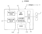
図1及び図5において、照明器具状態監視装置21は、照明器具1の調光率、ランプ2の点灯/消灯等の調光状態を監視、記録し、制御し、他設備への情報伝達を行うものである。
この照明装置状態監視装置21は、リモコン10又は照明器具コントローラ3から別の照明器具コントローラ3へ送信される赤外線信号を受信する赤外線信号受信部22と、受信した赤外線信号から照明器具1の調光率、消費電力等を演算するCPU23と、演算した照明器具1の調光率、消費電力等を表示する表示部24と、演算した照明器具1の調光率、消費電力等を記憶する記憶部25と、単独、複数及び時系列の調光情報の表示や記録の指示を行う操作部26と、受信した赤外線信号を同一又は別の照明器具コントローラ3に伝達又は中継する赤外線信号送信部27と、集中制御装置31に有線で消費電力等の調光情報や記憶部25の格納された調光情報を送ったり、集中制御装置31からの情報を受け取る外部入出力部28と、記憶部25に記憶された調光情報を記録出力するための記録出力部29と、時刻を計時して測定時刻等のタイムスタンプを付加するためのタイマ部30とで構成されている。
【0012】
また、照明装置状態監視装置21の記憶部25には、図5に示すように照明器具1の調光率と消費電力の関係を示す調光率−消費電力テーブルTが記憶格納されている。
なお、赤外線信号受信部22は赤外線受信素子を含む回路で構成され、CPU23はパソコンで構成され、表示部24はCRT等であり、記憶部25はRAM、HDD等の記憶素子/媒体で形成され、操作部26は例えばキーボード等であり、赤外線信号送信部27は赤外線送信素子を含む回路で構成され、外部入出力部28はRS−232Cやイーサネット(登録商標)等で構成され、記録出力部29は例えばプリンタやペンレコーダ等記録計等であり、タイマ部30は時刻を計時する時計である。また、集中制御装置31はビルの部屋、階又はビル全体の照明器具を集中管理し、制御するものである。
【0013】
次に、本発明の実施の形態に係る照明装置状態監視システムの動作について説明する。
まず、その前にリモコン10を用いて例えば4つの照明器具1に対して行う調光制御について説明する。
ここではリモコン10により4つの照明器具1が所定の調光率で点灯制御され、それ以降に調光率を代える場合について説明する。
例えば、リモコン10の赤外線送信部16より、特定のアドレス4の照明器具1の照明器具コントローラ3に対して、調光制御情報である例えば光出力UPの指令を赤外線信号で送信するときには、送信される赤外線信号に、さらにUPさせるべき照明器具のアドレス情報を付与する。このとき、リモコン10から送信する赤外線信号はアドレス4の照明器具1の照明器具コントローラ3ではなく、アドレス1の照明器具1の照明器具コントローラ3に向けて送信したとする。
ここで、アドレス1の照明器具1の照明器具コントローラ3は受信した赤外線信号が自分自身(アドレス1)に対する指令ではないことを器具制御部12で判断し、ランプの光出力を増加させる制御は行わず、その受信した赤外線信号と同じ内容の赤外線信号を器具赤外線送信部14から送信する。
【0014】
次に、アドレス1の照明器具1の照明器具コントローラ3から送信された赤外線信号は、直接もしくは床面の反射によってアドレス2の照明器具1の照明器具コントローラ3で受信される。アドレス2の照明器具1の照明器具コントローラ3は前述のアドレス1の照明器具1の照明器具コントローラ3と同様に、自分自身に対する指令でないことから、その受信した赤外線信号と同じ内容の赤外線信号を器具赤外線送信部14から送信する。同様にアドレス2から送信された赤外線信号はアドレス3の照明器具1で受信されるが、ここも同様に自分自身に対する指令でないことから、その受信した赤外線信号と同じ内容の赤外線信号を器具赤外線送信部14から送信する。
【0015】
次に、アドレス3の照明器具1の照明器具コントローラ3が送信した赤外線信号をアドレス4の照明器具1の照明器具コントローラ3が受信した場合は、受信した赤外線信号は自分自身(アドレス4)に対する指定であることから、受信した赤外線信号を器具制御部12で解読処理し、アドレス4の照明器具1の光出力を増加するよう点灯回路部11を制御する。このとき、動作検出部12aで出力しているランプ2の光出力の度合いを示す調光率が検出され、アドレス4の照明器具1の照明器具コントローラ3の記憶部13には、出力しているランプの光出力の度合いを示す調光率が記憶格納される。
【0016】
次に、リモコン10からアドレス4の照明器具1の動作情報、ここでは例えば、現在の点灯しているランプ2の調光率がいくつなのかを要求する赤外線信号がリモコン10の赤外線信号送信部16から送信された場合、リモコン10から送信された赤外線信号がアドレス1の照明器具1の照明器具コントローラ3で受信された場合は、自分自身(アドレス1)に対する要求ではないことを器具制御部12で判断し、器具赤外線受信部15で受信した赤外線信号と同じ内容の赤外線信号を器具赤外線送信部14が送信する。ここで、この赤外線信号をアドレス2の照明器具1の照明器具コントローラ3が受信したとすると、アドレス1の照明器具1が受信した場合と同様に受信した赤外線信号と同じ内容の赤外線信号を送信する。さらに、アドレス3の器具が受信した場合も同様である。
【0017】
この赤外線信号をアドレス4の照明器具1の照明器具コントローラ3が受信した場合、自分自身(アドレス4)に対する要求であることから、アドレス4の照明器具1の照明器具コントローラ3は記憶部13に記憶格納している調光率を器具制御部12で読み出し、器具赤外線送信部14よりリモコン10へリモコン10のアドレス0としたアドレス情報と調光率情報を付与した赤外線信号を送信する。
アドレス4の照明器具1の照明器具コントローラ3より送信された、調光率情報を付与した赤外線信号は、アドレス3の照明器具1の照明器具コントローラ3で受信された場合、自分自身(アドレス3)への指令信号ではなくリモコン10に対する信号であると器具制御部12で判断し、受信した赤外線信号と同じ内容の赤外線信号を送信する。以下同様にアドレス2の照明器具、アドレス1の照明器具が受信した場合でも自分自身に対する指令信号ではないことから、受信した赤外線信号と同様の赤外線信号を送信する。
【0018】
そして、リモコン10が赤外線受信部17で、アドレス4の照明器具1の照明器具コントローラ3が送信した調光率情報を付与した赤外線信号を受信し、又は他のアドレスの照明器具を経由したアドレス4の照明器具1の照明器具コントローラ3が送信したアドレス情報と調光率情報を付与した赤外線信号を受信した場合には、アドレス情報が自分自身のアドレス0と一致するので、リモコン制御部18によって赤外線信号の解読処理を行い、リモコン10の表示部19へアドレス4の照明器具1の調光率情報を表示する。
【0019】
また、照明器具1のランプ2がリモコン10の操作によって点灯させられた場合には、照明器具コントローラ3の記憶部13内にはカウンタが設けられており、図3に示すように当初はランプ2の点灯時間がゼロ時間でカウンタ値は0にセットされているが、ランプ2が点灯されると、器具制御部12の計時手段12bがランプ2の点灯時間を計測し、点灯時間がある所定時間(図3では10時間に設定)に達すると、器具制御部12は記憶部13内のカウンタ値を1として記憶部13に記憶格納する。次にまた所定時間(ここでは10時間)を計測すると、記憶部13内に記憶格納されていたカウンタ値1をカウントアップしてカウンタ値2として記憶部13に記憶格納する。このようにある所定時間を計時し、所定時間経過毎に記憶部13のカウンタ値を増加していくように動作する。
【0020】
ここで、リモコン10から照明器具1の照明器具コントローラ3に対して照明器具1の動作情報としてランプ2の累積点灯時間を要求する赤外線信号がリモコン10の赤外線信号送信部6から赤外線信号として送信された場合に、照明器具1の照明器具コントローラ3はリモコン10からの赤外線信号を受信し、器具制御部12で赤外線信号の解読処理を行い、記憶部13に格納されているカウンタ値を読み出す。ここで図3のA点で示すように、カウンタ値が5であればランプ2の累積点灯時間は50時間から60時間の間であることが分かる。
そこで、器具制御部12は累積点灯時間が略50時間であるという情報を付与した赤外線信号を生成し、器具赤外線送信部14を介して送信する。
次に、累積点灯時間が略50時間であるという情報を付与した赤外線信号をリモコン10の赤外線受信部17で受信すると、リモコン制御部18で赤外線信号の解読処理を行い、表示部19に照明器具1の累積点灯時間は略50時間である旨を表示する。
【0021】
なお、ここでは点灯時間計時のためのある所定時間を10時間としているが、この時間は特に決められたものではなく任意の時間で構わず、例えば1分毎にカウントアップするように計時すれば、より高精度に累積点灯時間を示すことができる。また、記憶部13は不揮発性メモリ等で構成するため、照明器具1の電源を遮断しランプ2を消灯し、再度電源投入により点灯させるような場合においても、記憶部13のカウンタ値は保持されるため、累積して点灯時間を計時することが可能である。
【0022】
なお、上述の動作説明において、リモコン10からアドレス4の照明器具1までの赤外線信号の通信順序をリモコン10送信→アドレス1(送信、受信)→アドレス2(受信、送信)→アドレス3(受信、送信)→アドレス4(受信)と説明し、アドレス4からリモコン3まではその逆順で説明したが、これは赤外線通信の状態をわかりやすく説明するためで、赤外線の床面反射の条件や、照明器具設置状態で赤外線の通信に関与する器具は異なる。
また、設置されている照明器具の全数が中継の為の赤外線通信に関与するとは限らず、リモコン10と対象照明器具のみの場合や、設置台数のうち数台が中継のために赤外線通信に関与する場合がある。
【0023】
また、上述の動作説明では、特定のアドレスをリモコン3から指定する例を挙げたが、グループ等を指定してもよい。また、記憶部13に記憶格納する動作情報は調光率だけでなく、ランプの点灯/消灯の情報や、照明器具自身又はランプの異常を示すような情報でも良く、この場合は容易にランプの状態や照明器具のメンテナンス情報を手元で確認することができる。
【0024】
以上のようにリモコン10により4つの照明器具1に対して調光制御を行っており、その調光制御の状態を照明器具状態監視装置21が監視している。
以下、照明器具状態監視装置21の動作について説明する。
照明器具状態監視装置21の赤外線信号受信部22では、リモコン10から照明器具1の照明コントローラ3へ、又は照明コントローラ3から別の照明コントローラ3へ、或いは照明器具1の照明コントローラ3からリモコン10へ送信される赤外線信号を受信している。
照明器具状態監視装置21のCPU23では赤外線信号受信部22が受信した赤外線信号に基づいて各照明器具1のランプの点滅状態、調光状態である調光率等の調光情報から消費電力を演算する。
即ち、照明装置状態監視装置21の記憶部25には、図5に示すように各照明器具1の調光率と消費電力の関係を示す調光率−消費電力テーブルTが記憶格納されており、また各照明器具1の照明コントローラ3の器具制御部12は累積点灯時間の情報を付与した赤外線信号を生成し、器具赤外線送信部14を介してリモコン10へ送信している。
【0025】
従って、CPU23では、例えば照明器具1について見ると、記憶部25に格納記憶されている照明器具1の調光率と消費電力の関係を示す調光率−消費電力テーブルTから調光率が98%と分かると、その調光率における消費電力は97Wであり、また照明器具1の照明器具コントローラ3の器具赤外線送信部14からリモコン10へ送信している累積点灯時間の情報とで消費電力量を演算することができることとなる。なお、照明器具1の点灯時間はリモコン10からの点灯/消灯の調光制御情報に基づいても演算することができる。
【0026】
また、CPU23が演算した照明器具1の消費電力量は、操作部26で表示操作することによって表示部24に表示される。従って、表示部24に表示された照明器具の消費電力量を見ることにより、リアルタイムに消費電力量の監視をすることができる。
このような照明装置状態監視装置21はリモコン10又は照明器具1の照明器具コントローラ3と赤外線通信を行うので、照明器具の消費電力を監視するために照明装置状態監視装置21を設置する場合には電気工事を不要とし、設置場所の制約もないことによりユーザに使い易いものとなっている。
さらに、表示部24に表示された照明器具1の消費電力量は、操作部26で記録出力操作すると、記録部出力部29により記録出力される。即ち、記録出力部29がプリンタであれば、照明器具1の消費電力量をプリントアウトすることができる。このとき、タイマ部30は時刻を計時しているので、測定時刻のタイムスタンプを付加してプリントアウトすることもできる。
【0027】
以上は、CPU23が照明器具1についての消費電力量を算出する例であるが、各照明器具にはアドレス番号がついているために、それぞれの照明器具を特定してそれについての消費電力量を演算することができる。
従って、操作部26で単独、複数又は全ての照明器具について表示するように表示操作することにより、単独、複数又は全ての照明器具についての消費電力量を表示部24に表示させることができ、必要に応じてこれらの時系列での消費電力量も表示させることができる。さらに、表示部24に表示されたこれらの消費電力量は、操作部26で記録出力操作すると、記録出力部29により記録出力される。
【0028】
また、表示部24には照明器具1の消費電力量だけでなく、照明器具1の点滅状態や調光状態である調光率も表示させることができることは勿論であり、記録出力部29に照明器具の点滅状態や調光状態も記録出力させることができる。
従って、照明器具の消費電力、点滅状態、調光状態である調光率を手元で確認できるため、照明器具の電力管理を容易に行うことができる。
また、記憶部25に記憶させた時系列の照明器具の調光状態や消費電力の情報を記録出力部29に記録出力させ、記録出力された情報に基づいて省エネ効果を検討したり、国際標準化機構の国際標準規格であるISO14001等の情報収集に用いることができる。
【0029】
さらに、記録出力部29に記録出力させた照明器具の調光状態や消費電力の情報から、逆に電力カット、例えば調光率を1割下げる等の制御を行うために、操作部26を操作して赤外線信号送信部27から照明器具1の照明器具コントローラ3に例えば調光率を1割下げるという修正した調光制御情報を送信することもできる。
また、照明装置状態監視装置21の外部入出力部28は、照明器具1の照明器具コントローラ3より受けた情報や、記憶部25に格納されている照明器具の調光状態や消費電力の情報を、直接は赤外線信号が届かない場所である外部の集中制御装置31に有線で送ったりすることもできる。
【0030】
このような複数の照明器具が部屋単位、又は階単位でリモコンでそれぞれ調光制御されている場合には、部屋単位、又は階単位の照明器具の調光状態や消費電力の情報を集中制御装置31が得ることにより、集中制御装置31は集中的に調光状態や消費電力を管理することができる。
さらに、外部入出力部28は外部の人感センサ等の信号を集中制御装置31を経由して受け取った場合に、その信号に基づいて照明器具1の照明器具コントローラ3に照明器具の点滅の信号を赤外線信号送信部27から送信することにより、人の有無に応じて照明器具1を点灯/消灯させるというよりきめの細かい調光制御も可能となる。なお、これらの動作は操作部26で操作してCPU23に指示することにより行う。
また、外部入出力部28は、照明器具コントローラ3から受信した情報を赤外線信号送信部27より同一、又は他の照明器具コントローラ3に中継、伝達することもできる。
【0031】
また、この実施の形態では、リモコン10を親機とし、複数の照明器具1の照明器具コントローラ3を子機及び中継器とし、リモコン10から照明器具1に対する調光制御情報を出すと、その調光制御情報が複数の照明器具1の照明器具コントローラ3で受信されるようにしているが、リモコン10に代わる固定式の親機としてもよく、さらに複数の照明器具1の照明器具コントローラ3のうちの1つに照度センサ等を設けてそれを親機としてもよいことは勿論である。
また、照明装置状態監視装置21の操作部26にリモコン10と同様の機能を持たせるようにすることもできる。
【0032】
【発明の効果】
以上のように本発明によれば、複数の照明器具の子機に相当する照明器具コントローラが親機から受信した赤外線信号の調光制御情報に基づいてランプに対して調光制御を行い、必要に応じて親機から受信した赤外線信号を送信するようにして複数の照明器具が調光制御されている場合に、照明器具状態監視装置の監視制御手段は、その赤外線信号受信部が受信した親機又は子機からの赤外線信号の調光制御情報に基づいて照明器具の調光情報を演算して求めるようにしたので、その照明器具の調光情報を監視することが可能となるという効果がある。
また、照明装置状態監視装置は親機又は照明器具の子機と赤外線通信を行うので、照明器具の消費電力を監視するために照明装置状態監視装置を設置する場合には電気工事を不要とし、設置場所の制約もないことによりユーザに使い易いものとなるという効果がある。
【図面の簡単な説明】
【図1】本発明の実施の形態に係る照明器具状態監視システムの構成を示すブロック図。
【図2】同照明器具状態監視システムの照明器具の構成を示すブロック図。
【図3】同照明器具状態監視システムの動作を示すランプ点灯時間−記憶部カウンタ値の図。
【図4】同照明器具状態監視システムのリモコンの構成を示すブロック図。
【図5】同照明器具状態監視システムの照明器具状態監視装置の構成を示すブロック図。
【図6】同照明装置状態監視システムの動作を示す調光率−消費電力の関係図である。
【符号の説明】
1 照明器具、2 ランプ、3 照明器具コントローラ、10 リモコン(親機)、21 照明器具状態監視装置、22赤外線信号送信部、23 CPU(監視制御手段)、24 表示部、25 記憶部、26 操作部、27 赤外線信号送信部、28 外部入出力部、29 記録部、30 タイマ部。[0001]
TECHNICAL FIELD OF THE INVENTION
The present invention relates to a lighting fixture state monitoring system that enables, for example, monitoring, recording, controlling, and transmitting information to other facilities of dimming states such as power consumption of a plurality of lighting apparatuses.
[0002]
[Prior art]
A conventional watt-hour meter uses power of various electric devices in a housing provided between an indoor power line to which various electric devices such as a television, a refrigerator, and a lighting device are connected and a power line extending from an outdoor power line. It is configured so as to incorporate a power amount measuring device for measuring the amount (for example, see Patent Document 1).
[0003]
[Patent Document 1]
JP-A-2001-28093 (
[0004]
[Problems to be solved by the invention]
A conventional watt-hour meter is configured such that a housing provided between an indoor power line and a power line extending from an outdoor power line has a built-in watt-hour meter for measuring the power consumption of various electric devices. Therefore, the installation of the watt-hour meter requires electric work, and the installation place of the watt-hour meter can be used for the power line, and there is a problem that there is a restriction on the place where the maintenance is easy. there were.
[0005]
The present invention has been made in order to solve such a problem, and it is possible to monitor the electric energy of a lighting fixture in real time, thereby eliminating the need for electrical work when measuring the electric energy of the lighting fixture. It is an object of the present invention to obtain a lighting equipment condition monitoring system which eliminates restrictions on installation locations and the like and is more user-friendly.
[0006]
[Means for Solving the Problems]
A lighting fixture condition monitoring system according to the present invention has a function of transmitting light control control information as an infrared signal and a function of performing light control on a lamp based on the light control information of the infrared signal received from the master. And a plurality of luminaires having a luminaire controller corresponding to a slave unit having a function of transmitting the infrared signal as required, and receiving an infrared signal transmitted by the master unit and an infrared signal of a luminaire controller of each luminaire. A lighting fixture status monitoring system for monitoring the dimming control state of the lighting fixture by performing an infrared signal transmitted by the master unit and lighting of each lighting fixture. An infrared signal receiving unit that receives the infrared signal of the fixture controller, and calculates the dimming information of the lighting fixture based on the dimming control information of the infrared signal received by the infrared signal receiving unit Those having a monitoring control means for obtaining Te.
[0007]
BEST MODE FOR CARRYING OUT THE INVENTION
FIG. 1 is a block diagram showing a configuration of a lighting fixture condition monitoring system according to an embodiment of the present invention, FIG. 2 is a block diagram showing a configuration of a lighting fixture of the lighting fixture condition monitoring system, and FIG. FIG. 4 is a block diagram showing a configuration of a remote control of the lighting fixture condition monitoring system, and FIG. 5 is a block diagram showing a configuration of a remote control of the lighting fixture condition monitoring system. FIG. 6 is a block diagram showing the configuration, and FIG. 6 is a relationship diagram between the dimming rate and the power consumption showing the operation of the lighting fixture state monitoring system.
1 and 2, the lighting device includes four
Each
[0008]
The
[0009]
Each
[0010]
The
In FIG. 1, the infrared signal transmitted from the
[0011]
1 and 5, a lighting fixture
The lighting device
[0012]
In addition, the
Note that the infrared
[0013]
Next, the operation of the lighting device state monitoring system according to the embodiment of the present invention will be described.
First, dimming control performed on, for example, four
Here, a case will be described in which the lighting of the four
For example, when the
Here, the
[0014]
Next, the infrared signal transmitted from the
[0015]
Next, when the
[0016]
Next, the
[0017]
When the
When the infrared signal to which the dimming rate information is added is transmitted from the
[0018]
Then, the
[0019]
When the
[0020]
Here, an infrared signal requesting the cumulative lighting time of the
Therefore, the
Next, when an infrared signal provided with information indicating that the cumulative lighting time is approximately 50 hours is received by the
[0021]
Note that, here, a predetermined time for lighting time measurement is set to 10 hours, but this time is not particularly determined and may be an arbitrary time. For example, if the time is counted up every minute, Thus, the accumulated lighting time can be indicated with higher accuracy. Further, since the
[0022]
In the above description of the operation, the communication order of the infrared signal from the
Also, not all of the installed lighting fixtures are involved in infrared communication for relaying, and only the
[0023]
In the above description of the operation, an example in which a specific address is specified from the
[0024]
As described above, dimming control is performed on the four
Hereinafter, the operation of the lighting fixture
In the infrared
The
That is, the
[0025]
Therefore, in the
[0026]
The power consumption of the
Since such a lighting device
Further, the power consumption of the
[0027]
The above is an example in which the
Therefore, by performing a display operation on the
[0028]
The
Accordingly, the power consumption of the lighting fixture, the dimming rate in the blinking state, and the dimming state can be checked at hand, so that the power management of the lighting fixture can be easily performed.
Further, the information on the dimming state and the power consumption of the time-series lighting fixtures stored in the
[0029]
Further, the user operates the
Further, the external input /
[0030]
In the case where such a plurality of lighting fixtures are individually controlled by a remote controller in units of rooms or floors, the information on the dimming state and power consumption of the lighting fixtures in units of rooms or floors is centrally controlled. As a result, the
Further, when the external input /
In addition, the external input /
[0031]
Also, in this embodiment, when the
Further, the
[0032]
【The invention's effect】
As described above, according to the present invention, the lighting fixture controller corresponding to the slave units of the plurality of lighting fixtures performs the dimming control on the lamp based on the dimming control information of the infrared signal received from the master unit, and In the case where a plurality of lighting fixtures are subjected to dimming control by transmitting an infrared signal received from the master unit according to the condition, the monitoring control means of the lighting fixture state monitoring device transmits the infrared signal received by the infrared signal receiving unit. Since the dimming information of the lighting fixture is calculated and obtained based on the dimming control information of the infrared signal from the handset or the slave unit, it is possible to monitor the dimming information of the lighting fixture. is there.
Also, since the lighting device condition monitoring device performs infrared communication with the parent device or the slave device of the lighting device, when installing the lighting device condition monitoring device to monitor the power consumption of the lighting device, electrical work is unnecessary, Since there is no restriction on the installation place, there is an effect that it becomes easy for the user to use.
[Brief description of the drawings]
FIG. 1 is a block diagram showing a configuration of a lighting fixture condition monitoring system according to an embodiment of the present invention.
FIG. 2 is a block diagram showing a configuration of a lighting fixture of the lighting fixture condition monitoring system.
FIG. 3 is a diagram showing a lamp lighting time versus a storage unit counter value showing an operation of the lighting fixture condition monitoring system.
FIG. 4 is a block diagram showing a configuration of a remote controller of the lighting fixture condition monitoring system.
FIG. 5 is a block diagram showing a configuration of a lighting fixture state monitoring device of the lighting fixture state monitoring system.
FIG. 6 is a diagram showing the relationship between the dimming rate and the power consumption showing the operation of the lighting device state monitoring system.
[Explanation of symbols]
REFERENCE SIGNS
Claims (5)
前記照明器具状態監視装置は、
親機が送信する赤外線信号及び各照明器具の照明器具コントローラの赤外線信号を受信する赤外線信号受信部と、
赤外線信号受信部が受信した赤外線信号の調光制御情報に基づいて照明器具の調光情報を演算して求める監視制御手段と、
を有していることを特徴とする照明器具状態監視システム。A base unit for transmitting dimming control information as an infrared signal, a function for performing dimming control on the lamp based on dimming control information of the infrared signal received from the base unit, and transmitting the infrared signal as necessary A plurality of lighting fixtures having a lighting fixture controller corresponding to a slave unit having a function, and an infrared signal transmitted from the master unit and an infrared signal of the lighting fixture controller of each lighting fixture are received to monitor the dimming control state of the lighting fixture. A lighting fixture condition monitoring system having a lighting fixture condition monitoring device,
The lighting fixture condition monitoring device,
An infrared signal receiving unit that receives an infrared signal transmitted by the master unit and an infrared signal of a lighting fixture controller of each lighting fixture,
Monitoring control means for calculating and calculating the dimming information of the lighting fixture based on the dimming control information of the infrared signal received by the infrared signal receiving unit,
A lighting fixture condition monitoring system, comprising:
前記調光情報を表示する表示部、前記調光情報を外部に送る外部入出力部、前記調光情報を記録出力する記録出力部、前記調光情報を記憶する記憶部、前記赤外線信号を送信する赤外線信号送信部のいずれか1つ又はこれらを任意に組合せたものを有することを特徴とする請求項1記載の照明器具状態監視システム。The lighting fixture condition monitoring device,
A display unit for displaying the dimming information, an external input / output unit for sending the dimming information to the outside, a recording output unit for recording and outputting the dimming information, a storage unit for storing the dimming information, and transmitting the infrared signal The lighting equipment condition monitoring system according to claim 1, further comprising any one of the infrared signal transmitting units or a combination thereof.
Priority Applications (1)
| Application Number | Priority Date | Filing Date | Title |
|---|---|---|---|
| JP2003051153A JP2004259657A (en) | 2003-02-27 | 2003-02-27 | Lighting apparatus state monitor system |
Applications Claiming Priority (1)
| Application Number | Priority Date | Filing Date | Title |
|---|---|---|---|
| JP2003051153A JP2004259657A (en) | 2003-02-27 | 2003-02-27 | Lighting apparatus state monitor system |
Publications (1)
| Publication Number | Publication Date |
|---|---|
| JP2004259657A true JP2004259657A (en) | 2004-09-16 |
Family
ID=33116369
Family Applications (1)
| Application Number | Title | Priority Date | Filing Date |
|---|---|---|---|
| JP2003051153A Pending JP2004259657A (en) | 2003-02-27 | 2003-02-27 | Lighting apparatus state monitor system |
Country Status (1)
| Country | Link |
|---|---|
| JP (1) | JP2004259657A (en) |
Cited By (9)
| Publication number | Priority date | Publication date | Assignee | Title |
|---|---|---|---|---|
| JP2007287671A (en) * | 2006-03-23 | 2007-11-01 | Mitsubishi Electric Corp | Discharge lamp lighting device, lighting control system, and control management system |
| CN102355772A (en) * | 2008-01-28 | 2012-02-15 | 上海市南供电设计有限公司 | Single-lamp energy-saving controller for street lamps |
| KR101178426B1 (en) | 2011-04-18 | 2012-08-30 | 임태환 | Apparatus and method for management of energy consumption using remote control |
| JP2012227013A (en) * | 2011-04-20 | 2012-11-15 | Panasonic Corp | Illumination system |
| CN104735875A (en) * | 2015-03-24 | 2015-06-24 | 上海大学 | LED illumination real-time simulation control system and simulation control method thereof |
| US9750117B2 (en) | 2015-06-01 | 2017-08-29 | Panasonic Intellectual Property Management Co., Ltd. | Lighting system, lighting device, and method of communication in lighting system |
| US9854652B2 (en) | 2016-01-15 | 2017-12-26 | Panasonic Intellectual Property Management Co., Ltd. | Lighting apparatus and lighting system |
| WO2018150158A1 (en) * | 2017-02-16 | 2018-08-23 | Robert Wilkes | Lighting apparatus and system |
| US10582594B2 (en) | 2017-08-09 | 2020-03-03 | Panasonic Intellecutal Property Management Co., Ltd. | Lighting system, wireless controller, and control method |
-
2003
- 2003-02-27 JP JP2003051153A patent/JP2004259657A/en active Pending
Cited By (9)
| Publication number | Priority date | Publication date | Assignee | Title |
|---|---|---|---|---|
| JP2007287671A (en) * | 2006-03-23 | 2007-11-01 | Mitsubishi Electric Corp | Discharge lamp lighting device, lighting control system, and control management system |
| CN102355772A (en) * | 2008-01-28 | 2012-02-15 | 上海市南供电设计有限公司 | Single-lamp energy-saving controller for street lamps |
| KR101178426B1 (en) | 2011-04-18 | 2012-08-30 | 임태환 | Apparatus and method for management of energy consumption using remote control |
| JP2012227013A (en) * | 2011-04-20 | 2012-11-15 | Panasonic Corp | Illumination system |
| CN104735875A (en) * | 2015-03-24 | 2015-06-24 | 上海大学 | LED illumination real-time simulation control system and simulation control method thereof |
| US9750117B2 (en) | 2015-06-01 | 2017-08-29 | Panasonic Intellectual Property Management Co., Ltd. | Lighting system, lighting device, and method of communication in lighting system |
| US9854652B2 (en) | 2016-01-15 | 2017-12-26 | Panasonic Intellectual Property Management Co., Ltd. | Lighting apparatus and lighting system |
| WO2018150158A1 (en) * | 2017-02-16 | 2018-08-23 | Robert Wilkes | Lighting apparatus and system |
| US10582594B2 (en) | 2017-08-09 | 2020-03-03 | Panasonic Intellecutal Property Management Co., Ltd. | Lighting system, wireless controller, and control method |
Similar Documents
| Publication | Publication Date | Title |
|---|---|---|
| US7965174B2 (en) | Integrated building device monitoring network | |
| US8452554B2 (en) | Networked device with power usage estimation | |
| US20150185752A1 (en) | Wireless Load Control System | |
| US9191107B2 (en) | Hazardous location visible light communication networks | |
| KR101182599B1 (en) | Apparatus and method for controlling of power consumption appliance | |
| JP5170361B2 (en) | Lighting system | |
| JP2014003600A (en) | Power line communication system | |
| US20160056971A1 (en) | Wireless lighting control | |
| JP2004259657A (en) | Lighting apparatus state monitor system | |
| JP2014241024A (en) | Sensor network system, server device, and sensor network control program | |
| JP2008091160A (en) | Lighting control system | |
| JP2014195227A (en) | Electric apparatus remote control system | |
| JP2010175388A (en) | Power consumption monitoring system | |
| JP2002260877A (en) | Illumination device | |
| WO2012086705A1 (en) | Apparatus management system, and mobile terminal which is used in apparatus management system | |
| JP7100916B2 (en) | Lighting system | |
| KR20180110716A (en) | IoT SYSTEM USING LAMPS AND A METHOD FOR CONTROLLING THE SAME | |
| KR102107651B1 (en) | A system for management of an air-conditioning unit | |
| JP2012509527A (en) | Power saving device and system, and methods of use and manufacture thereof | |
| JP2007329781A (en) | Monitoring device | |
| JP5003943B2 (en) | Monitoring terminal | |
| KR20100030394A (en) | Standby power control system, standby power control device, and standby power control method | |
| JP4566342B2 (en) | Measurement control system | |
| KR200377874Y1 (en) | The cctv camera combine to intensity of illumination measurement and that of using lighting control system | |
| KR20190052442A (en) | Iot-based smart lighting module |