JP2004257525A - Gas supply device, and method for controlling the same - Google Patents
Gas supply device, and method for controlling the same Download PDFInfo
- Publication number
- JP2004257525A JP2004257525A JP2003051531A JP2003051531A JP2004257525A JP 2004257525 A JP2004257525 A JP 2004257525A JP 2003051531 A JP2003051531 A JP 2003051531A JP 2003051531 A JP2003051531 A JP 2003051531A JP 2004257525 A JP2004257525 A JP 2004257525A
- Authority
- JP
- Japan
- Prior art keywords
- filling
- pressure
- gas supply
- amount
- gas
- Prior art date
- Legal status (The legal status is an assumption and is not a legal conclusion. Google has not performed a legal analysis and makes no representation as to the accuracy of the status listed.)
- Granted
Links
Images


Abstract
Description
【0001】
【発明の属する技術分野】
本発明は、ガス充填終了後に充填ホース内に残留するガス残量を総充填量から補正するよう構成されたガス供給装置及びその制御方法に関する。
【0002】
【従来の技術】
例えば、天然ガスを圧縮した圧縮天然ガス(CNG)等を別のタンクに供給するガス供給装置としては、例えば、圧縮機、蓄ガスユニットとディスペンサユニットとを有しており、ディスペンサユニットは流量計、制御弁、圧力センサを有する(例えば、特許文献1参照)。
【0003】
このガス供給装置では、圧縮機により所定圧以上(例えば25MPa)に昇圧されたガスが供給源としてのガス供給タンクに貯留されている。そして、燃料供給を受ける自動車が到着すると、充填ホースの先端に設けられた充填カップリングを自動車の燃料タンク(被充填タンク)の接続部(カップリング)に結合させる。尚、自動車側の接続部は、逆止弁が内蔵されており、充填カップリングが結合され燃料タンクの圧力よりも充填ホース側圧力が大きいとき圧力差によって逆止弁が開弁する。
【0004】
その後、充填カップリングの三方弁が切り替え操作されてガス供給タンクに貯留されたガスが充填ホース及び充填カップリングを介して自動車の燃料タンクに充填される。このとき、自動車の燃料タンクには、ガスが残っているが、ガス供給タンクの圧力(供給圧力)が燃料タンクの圧力よりも十分に大きいので、圧力差によりガス充填が行われる。
【0005】
そして、ガス供給タンクに貯められたガスを自動車の燃料タンクに供給され燃料タンク内が所定の満タン圧(例えば、20MPa)に達するまで充填し、充填カップリングの三方弁を切り替えることによりガス充填が終了する。
【0006】
ガス充填が終了すると、作業者は、充填カップリングを自動車側のカップリングから分離させ、充填カップリングをカップリング収納部に収納させる。
【0007】
また、自動車の燃料タンクへのガス供給量は、流量計により計測されており、燃料タンクに充填された総流量を知ることができ、燃料タンクに充填された圧力は圧力センサ(圧力測定手段)により測定できる。さらに、充填ホースの先端には、燃料タンクの接続部に接続される充填カップリングが設けられており、この充填カップリングはガス供給前に自動車の燃料タンクに接続され、ガス充填完了後に燃料タンクから外される。
【0008】
ところが、充填ホース内の圧力が高圧になっていると充填カップリングを燃料タンクの接続部から外すことができない。そのため、作業者は、手動式の三方弁を切り換えて充填カップリング内のガスを大気中に放出するか、あるいはドレンタンクに回収させて充填ホース内を大気圧に減圧させる。このように、充填カップリングの減圧操作を行うことにより、上記充填カップリングを燃料タンクの接続部から外すことが可能になる。
【0009】
【特許文献1】
特開平8−68496号公報
【0010】
【発明が解決しようとする課題】
上記構成のガス供給装置では、2台の自動車に連続して燃料タンクに満タン充填を行う場合、燃料タンクの耐圧基準値により満タン圧力が決められているので、充填ホースに残留する充填開始前圧力と今回充填終了圧力とがほぼ同一であるので、誤差が生じない。
【0011】
しかるに、1台目の自動車に対して任意の所定圧力でプリセット充填した後に2台目の自動車に対して満タン充填を行う場合、充填ホースに残留する充填開始前圧力と今回充填終了圧力が同一でないので、誤差が生じる。
【0012】
さらに、ガス供給装置においては、流量計が制御弁の上流にあるので、制御弁を閉弁した状態で充填カップリングを自動車の接続部に接続する場合、充填ホースに残留するガスが充填カップリングを介して自動車の燃料タンクに供給されるガス供給量を測定することができない。
【0013】
一方、流量計で計測できるのは、今回の充填開始(開閉弁、制御弁の開弁)から今回の充填終了(開閉弁、制御弁の閉弁)までの間に供給されたガス供給量である。また、圧力センサにより検出できるのは、制御弁より下流の圧力値であり、充填ホースの圧力である。
【0014】
従って、ガス供給装置においては、充填開始される前の充填カップリングの接続によって充填ホース内に残留していたガスがどれだけ自動車側に供給されたかを流量計で測定できず、正確なガス供給量が分からないので、充填開始前のホース残留圧力と充填終了後のホース残留圧力との圧力差による流量誤差が生じてしまうという問題がある。
【0015】
また、充填開始される前(充填カップリングの接続前)に充填ホース内に残留していたガス圧力よりも、充填終了後のホース残留圧力が高くなった場合には、この圧力差分のガスは流量計により測定されるが自動車側に供給されないことになり流量誤差が生じてしまうという問題がある。
そこで、本発明は上記課題を解決したガス供給装置及びその制御方法を提供することを目的とする。
【0016】
【課題を解決するための手段】
上記課題を解決するため、本発明は以下のような特徴を有する。
上記請求項1記載の発明は、圧力測定部により測定されたガス充填開始前圧力値と充填終了時点のガス充填終了圧力値との圧力差を求め、この圧力差に流量計から充填カップリングまでのガス供給経路内の容積を乗算して充填量補正値を演算する充填量補正演算手段と、流量計により測定されたガスの供給量と充填量補正演算手段により演算された充填量補正値とから充填カップリングから充填された充填量を演算する充填量演算手段と、を備えており、充填開始前圧力と充填終了時圧力に差があっても流量計から充填カップリングまでのガス供給経路内の圧力の差異による流量誤差を無くすように流量補正することが可能になる。
【0017】
上記請求項2記載の発明は、圧力測定部により測定されたガス充填開始前圧力値と任意に設定した圧力値との圧力差を求め、この圧力差に流量計から充填カップリングまでのガス供給経路内の容積を乗算して開始前充填量補正値を演算する充填量補正演算手段と、流量計により測定されたガスの供給量と充填量補正演算手段により演算された充填量補正値とから充填カップリングから充填された充填量を演算する充填量演算手段と、を備えており、充填開始前圧力が変動しても開始前充填量補正値を求めて流量計から充填カップリングまでのガス供給経路内の圧力の差異による流量誤差を無くすように流量補正することが可能になる。
【0018】
上記請求項3記載の発明は、圧力測定部により測定された充填終了時点のガス充填終了圧力値と任意に設定した圧力値との圧力差を求め、この圧力差に流量計から充填カップリングまでのガス供給経路内の容積を乗算して終了時充填量補正値を演算する充填量補正演算手段と、流量計により測定されたガスの供給量と充填量補正演算手段により演算された充填量補正値とから充填カップリングから充填された充填量を演算する充填量演算手段と、を備えており、充填終了時圧力が変動しても終了時充填量補正値を求めて流量計から充填カップリングまでのガス供給経路内の残留圧力の差異による流量誤差を無くすように流量補正することが可能になる。
【0019】
上記請求項4記載の発明は、充填終了時におけるガス充填量の所定量手前から充填終了時までの間に充填量補正演算を行うものであり、流量計から充填カップリングまでのガス供給経路内の圧力の差異による流量を正確に補正することが可能になる。
【0020】
上記請求項5記載の発明は、ガスの供給流量を制御するためにガス供給経路に設けられた制御弁と、制御弁によるガスの供給流量を制御する供給量制御手段とを設け、供給量制御手段は、充填終了時におけるガス充填量の所定量手前からガスの供給量を所定の流量に低下させるものであり、できるだけ低い流量で一定制御することによって、ディスペンサーの圧力測定部と燃料タンクとの圧力差を極力等しくし、流量計から充填カップリングまでのガス供給経路内に充填される充填量を正確に測定することができるので、充填開始前圧力と充填終了時圧力に差があっても流量を正確に補正することが可能になる。
【0021】
上記請求項6記載の発明は、ガスの供給圧力を制御するためにガス供給経路に設けられた制御弁と、制御弁によるガスの供給圧力を制御する供給圧力制御手段とを設け、供給圧力制御手段は、充填終了時におけるガス充填量の所定量手前からガスの供給圧力を所定の圧力に調節するものであり、できるだけ小さな弁開度で一定制御することによって、ディスペンサーの圧力測定部と燃料タンクとの圧力差を極力等しくし、充填終了時における流量測定を正確に行うことで、充填終了時圧力が変動しても流量を正確に補正することが可能になる。
【0022】
上記請求項7記載の発明は、ガスの供給流量を制御するためにガス供給経路に設けられた制御弁と、制御弁によるガスの供給流量を制御する供給量制御手段とを設け、供給量制御手段は、充填終了時におけるガス充填量の所定量手前からガスの供給量を徐々に低下させるものであり、できるだけ低い流量でディスペンサーの圧力測定部によって測定することにより燃料タンクとの圧力差を極力等しくし、充填終了時における流量測定を正確に行うことで、充填終了時圧力が変動しても流量を正確に補正することが可能になる。
【0023】
上記請求項8記載の発明は、流量計から充填カップリングまでのガス供給経路内の容積は、充填カップリングを閉弁した状態を維持した状態で、開閉弁を閉弁している際において圧力測定部により計測された充填前圧力値と、当該状態において開閉弁を開弁させた際における圧力測定部により計測された充填後圧力値とから、圧力差を演算し、当該圧力差と充填前圧力値から充填後圧力値までに圧力を昇圧させた際に流量計で測定された供給量とに基づき求めるものであり、流量計から充填カップリングまでのガス供給経路内の容積を正確に求めて、圧力差に伴う充填量の誤差を正確に補正することが可能になる。
【0024】
上記請求項9記載の発明は、充填量補正演算手段が演算した補正量を流量計で測定された供給量から減算するものであり、充填開始前圧力と充填終了時圧力に差があっても流量計から充填カップリングまでのガス供給経路内の圧力の差異による流量誤差を無くすように流量補正することが可能になる。
【0025】
【発明の実施の形態】
以下、図面と共に本発明の実施の形態について説明する。
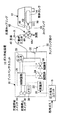
図1は本発明になるガス供給装置のシステム構成を示す構成図である。
図1中、ガス供給装置10は、例えば自動車12の燃料タンク(被充填容器)14に都市ガスを所定圧力に圧縮した圧縮天然ガス(CNG)を供給するガス供給ステーションなどに設置されている。尚、上記圧縮天然ガスは一例であり、ガス供給装置10が扱うガスは、これに限らず圧縮されて使用される他のガスを含む。
【0026】
ガス供給装置10は、大略、都市ガスを所定圧力に昇圧する圧力発生ユニット16と、圧力発生ユニット16により圧縮されたガスを燃料タンク14に供給するためのディスペンサユニット18とより構成されている。
【0027】
圧力発生ユニット16は、中圧(家庭で使用される圧力よりも高い圧力)で給送される中圧管路(図示せず)を介して供給された都市ガスを圧縮する多段式のコンプレッサを有する。本実施例においては、上記燃料タンク14の最高圧力が20MPaとした場合、圧力発生ユニット16では25MPaの圧力に加圧する。
【0028】
さらに、圧力発生ユニット16の吐出口には、ディスペンサユニット18のガス供給管路20が接続されており、ガス供給管路20には燃料タンク14に供給されたガス供給量を測定する流量計22と、ガス供給管路20を開閉する開閉弁24と、燃料タンク14に供給されるガス圧及び流量を所定値に制御する制御弁26と、燃料タンク14に供給された供給ガス圧を測定する圧力センサ(圧力測定部)28とが配設されている。
【0029】
ディスペンサユニット18の側面には、カップリング掛け30が設けられており、カップリング掛け30には、カップリングスイッチ32が設けられている。また、ディスペンサユニット18は、充填開始スイッチ34、充填停止スイッチ36が設けられている。
【0030】
また、ディスペンサユニット18は、上記流量計22、開閉弁24、制御弁26、圧力センサ28、カップリングスイッチ32、充填開始スイッチ34、充填停止スイッチ36に電気的に接続された制御回路38を有する。制御回路38は、マイクロコンピュータなどからなり、後述するように開閉弁24、制御弁26を制御する。
【0031】
制御回路38は、流量計22からの流量信号、及び圧力センサ28からの圧力信号、及びカップリングスイッチ32からのカップリング検出信号が入力されると共に、開閉弁24の開弁または閉弁制御、及び制御弁26の弁開度を調整して流量、圧力制御を行う。
【0032】
制御回路38のメモリ39には、圧力センサ28により測定されたガス充填開始前圧力値と充填終了時点のガス充填終了圧力値との圧力差を求め、この圧力差に流量計22から充填カップリング42までのガス供給経路内の容積(流量計22から下流のガス供給管路20及び充填ホース40の容積)を乗算して充填量補正値を演算する制御プログラム(充填量補正演算手段)が格納されている。また、制御回路38は、演算した補正量を総充填量から減算することにより、充填ホース40のガス充填開始前圧力値と充填終了時点での残留圧力の差異による流量誤差を補正する流量補正装置としても機能する。
【0033】
ディスペンサユニット18の側面から引出された充填ホース40は、一端がガス供給管路20に接続され、他端に充填カップリング42が連通されている。充填カップリング42は、作業者が手動操作する手動式三方弁44と、燃料タンク14のカップリング46に結合されるカップリング48とから構成されている。
【0034】
手動式三方弁44は、手動操作用ハンドル44aと、ガス供給側のaポートと、ガス吐出側のbポートと、脱圧側のcポートとを有する。手動式三方弁42のaポートには、充填ホース40が連通されており、bポートにはカップリング48が設けられている。また、手動式三方弁42のcポートは、充填終了後にカップリング48の残圧を外部(大気中または回収経路)に排出するための排気ポートである。
【0035】
また、燃料タンク14とカップリング46とを連通する管路50には、燃料タンク14に充填されたガスが充填カップリング42へ逆流しないように逆止弁52が配設されている。尚、逆止弁52の代わりに手動式の開閉弁を設ける構成としても良い。
【0036】
図2はガス充填開始からガス充填終了までの圧力変化及び流量変化の一例を示すグラフである。尚、図2において、グラフIは圧力センサ28により測定された圧力の変化を示し、グラフIIは流量計22により測定された流量の変化を示す。
図2のグラフIに示されるように、P1は充填開始前圧力、P2は充填開始圧力、P3は充填開始時の定流量制御終了圧力、P4は定圧上昇制御終了圧力、P5は充填終了時の定流量制御終了圧力である。
【0037】
グラフIは圧力センサ28により測定された圧力であり、燃料タンク14に充填される圧力、すなわち、ガス供給管路20及び充填ホース40の圧力変化を示している。そして、カップリング48を燃料タンク14のカップリング46に結合させ、手動式三方弁44のa,bポートを連通させると、充填ホース40内に残留するガスが燃料タンク14に供給される。これにより、充填ホース40内の圧力は、充填開始前圧力P1から今回充填開始圧力P2に低下する。
【0038】
このときの充填開始前の圧力変化ΔP(=P1−P2)は、充填開始前圧力P1と燃料タンク14の残圧及び容積によって変動する。充填開始前圧力P1は、前回充填がプリセット充填である場合、一定値ではないので、毎回異なる値になる。また、燃料タンク14の残圧は、運転者の判断で充填を行うので、毎回異なる値になる。
【0039】
従って、上記圧力変化ΔPは、毎回満タン充填を行う場合を除いて変動することになる。しかしながら、この圧力変化ΔPは、開閉弁24が閉弁された充填開始前の圧力変化であるので、充填ホース40から燃料タンク14へ供給されたガスの流量を流量計22によって計測することはできない。
【0040】
また、充填終了後の圧力変化ΔP’(=P4−P3)は、制御弁26の下流の充填による圧力上昇であり、燃料タンク14内への充填量のほか、同時に充填ホース40への充填量を含む。そして、充填終了後の圧力変化がΔP’(=P4−P3)>0の場合には、流量計22によって計測されるが流量計22より下流のガス供給管路20及び充填ホース40への充填量は燃料タンク14内に入らずガス供給管路20及び充填ホース40内に残ることになる。
【0041】
図2のグラフIIに示されるように、Q1は充填開始の流量、Q2は定圧上昇制御開始の流量、Q3は流量上昇分岐点の流量、Q4は絞り開始の流量、Q5は充填終了の流量、Q6は充填終了の流量である。
【0042】
尚、Q1〜Q2及びQ5〜Q6は、圧力センサ28の検出精度を安定的に行うため、低流量による定量制御が行われる。また、Q2〜Q4は定圧上昇制御に応じた流量変化を示す。
【0043】
ここで、流量計22により測定された積算流量を充填ホース40の充填開始圧力と充填終了圧力との圧力差に応じた補正量Kの演算方法について説明する。
補正量Kは、次式(1)により求まる。
【0044】
K=V×(Pe−Ps)/Pa …(1)
尚、(1)式のPaは大気圧、Vは流量計22より下流のガス供給管路20及び充填ホース40の内部に形成された流路の幾何容積である。
【0045】
そして、補正量Kが正の場合には、この補正量を流量計22で測定された積算流量から減算することにより正確な充填量を演算する。また、補正量Kが負の場合には、積算流量に補正量を加算して充填量表示値を補正する。
【0046】
なお、この充填量の補正は、充填終了の直前においての定流量制御を行っているときに行なわれる。
【0047】
ここで、定圧上昇制御(P3〜P4)から定流量制御(P4〜P5)への充填制御の切替条件は、残充填量または(定量設定量−現在の充填量)が予め設定された値に達したときであり、充填終了条件は満タン圧力(P5)または定量設定値(プリセット値)に達したときである。
前述した(1)式は、次のようになる。
【0048】
K={V×(P−Pe)/Pa}−{V×(P−Ps)/Pa}…(2)
(2)式のPは予め設定された設定圧力であり、ここでは満タン圧力である。そのため、この(2)式では、V×(P−Ps)/Paの演算を充填開始直後から行うことができる。そして、充填ホース40内が満タン圧力から充填開始して充填停止スイッチ36をオンに操作して充填途中でガス供給を停止しても充填開始時の流量誤差を補正することが可能になる。
【0049】
また、予め設定する充填ホース40の内容積(V)は、通常、設計寸法から既知となるが、以下のように実際の充填量から求めることにより、さらに精度が高まる。
【0050】
充填ホース40の圧力を大気圧(Pa)に減圧してから充填開始スイッチ34を操作することにより、開閉弁24を開弁し、ガス充填を開始する。このとき、充填カップリング44のカップリング48が自動車12のカップリング46に結合されていないことを保証するために、カップリングスイッチ32からの信号の有無により監視する。
【0051】
そして、満タン圧力(P5)に達すると、開閉弁24を閉弁して充填終了し、流量計22により計測された積算流量をメモリ39に記憶する。
【0052】
{計量値(体積値)/(満タン圧力/大気圧)}…(3)
この(3)式により流量計22より下流のガス供給管路20及び充填ホース40の幾何容積(V)を算出し、メモリ39に記憶する。この演算処理は、幾何容積設定モード等の特定の操作により行う。
【0053】
さらに、予め圧力に関するガスの圧縮係数データをデータベースに記憶させ、上記(1)(2)式をそのときの圧力に応じて圧縮係数の補正を行うことにより流量補正演算処理の精度が高められる。
【0054】
ここで、幾何容積設定モードが設定された場合に制御回路38が実行する制御処理の処理手順(請求項8の記載に相当する)について説明する。
【0055】
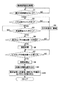
図3は制御回路38が実行する幾何容積設定モード処理を説明するためのフローチャートである。尚、幾何容積設定モードは、メンテナンス時あるいは充填ホース40の交換時などで行なわれる。
【0056】
幾何容積設定モードを設定する場合、例えば、設定操作を行う操作者は、予め手動式三方弁44のa,bポートを連通させることにより、充填ホース40内に残留するガスが大気中に放出されて充填ホース40の圧力を大気圧(Pa)に減圧させる。そして、手動式三方弁44の手動操作用ハンドル44aを操作してb,cポートを連通させ,aポートを遮断(閉弁状態)する。このように、充填ホース40の圧力を大気圧(Pa)にした状態で充填ホース40の圧力を上限圧力(満タン圧力)まで昇圧させることで、前述した流量計22から充填カップリング42までの幾何容積Vを正確に算出することが可能になる。
【0057】
図3に示されるように、制御回路38は、ステップS1(以下「ステップ」を省略する)において、ホース内容積設定モードが設定されたか否かを確認する。S1で操作者の操作により幾何容積設定モードが設定された場合、S2に進み、カップリングスイッチ32がオンかどうかをチェックする。
【0058】
カップリングスイッチ32がオンであるときは、カップリング掛け30に充填カップリング42が掛けられているものと判断してS3に進む。
【0059】
S3では、充填開始スイッチ34がオンかどうかをチェックする。S3において、充填開始スイッチ34がオンに操作されると、S4に進み、圧力センサ28により測定された圧力値と読み込み、充填ホース40の圧力が大気圧(Pa)かどうかをチェックする。
【0060】
S4において、圧力センサ28により測定された圧力値が大気圧(Pa)でない場合には、S5に進み、充填ホース40の圧力が大気圧(Pa)以上であることを表示すると共に、警報を発して報知する。この場合、操作者は、前述した手動式三方弁44の手動操作用ハンドル44aを開閉操作して充填ホース40に残留するガスを大気中に放出させて充填ホース40の圧力が大気圧(Pa)する。
【0061】
そして、再度、S2〜S4の処理を行う。上記S4において、圧力センサ28により測定された圧力値が大気圧(Pa)である場合には、S6に進み、開閉弁24を開弁させて、充填ホース40にガスを充填する。
【0062】
次のS7では、圧力センサ28により測定された圧力値が上限圧力(P5)に達したかどうかをチェックする。S7において、圧力センサ28により測定された圧力値が上限圧力(P5)に達した時点で、S8に進み、開閉弁24を閉弁させて、充填ホース40へのガス充填を停止する。
【0063】
そして、S9では、大気圧から上限圧力(P5)に達するまでの間に流量計22によって計測された流量値を読み込む。続いて、S10では、前述した(3)式により流量計22より下流のガス供給管路20及び充填ホース40の幾何容積(V)を算出し、メモリ39に記憶する。
【0064】
尚、上記説明では、充填ホース40の圧力を大気圧(Pa)にした状態で充填ホース40の圧力を上限圧力(満タン圧力)まで昇圧させることで、前述した流量計22から充填カップリング42までの幾何容積Vを正確に算出する方法について説明したが、これに限らず、開始圧力を大気圧(Pa)以外の任意の圧力、あるいは上限圧力を満タン圧力以外の任意の圧力(この場合、開始圧力より大きい圧力)に設定することも可能である。
【0065】
すなわち、流量計22から充填カップリング42までのガス供給経路内の容積は、充填カップリング42を閉弁した状態を維持した状態で、開閉弁22を閉弁している際において圧力センサ28により計測された充填前圧力値と、当該状態において開閉弁24を開弁させた際における圧力センサ28により計測された充填後圧力値とから、圧力差を演算し、当該圧力差と充填前圧力値から充填後圧力値までに圧力を昇圧させた際に流量計22で測定された供給量とに基づき求めることができる。
【0066】
ここで、制御回路38が実行する充填制御処理の処理手順について説明する。図4は制御回路38が実行する充填処理を説明するためのフローチャートである。
図4に示されるように、S11において、カップリングスイッチ32がオフになると、充填カップリング42がカップリング掛け30から外されたものと判断する。作業者は、充填カップリング42をカップリング掛け30から外した後、カップリング48を燃料タンク14のカップリング46に結合させる。
【0067】
そして、作業者は、手動式三方弁44の手動操作用ハンドル44aを回動操作してaポートとbポートとを連通させる。これにより、充填ホース40に残留していたガスが自動車12の燃料タンク14に供給され、充填ホース40の圧力は充填開始前圧力P1から今回充填開始圧力P2に低下する。
【0068】
次のS12では、圧力センサ28により測定された充填開始時の圧力値(ホース内圧力Ps=P1)を読み込み、メモリ39に記憶する。このとき、前回の充填処理において、メモリ39に記憶された充填開始時の圧力値は、消去される。
【0069】
続いて、S13に進み、充填開始スイッチ34がオンに操作されたかどうかをチェックする。S13において、充填開始スイッチ34がオフのときは、S14に移行してカップリングスイッチ32がオフかどうかをチェックする。S14において、カップリングスイッチ32がオンの場合には、充填カップリング42がカップリング掛け30に戻されたものと判断して上記S11に戻る。
【0070】
また、上記S14において、カップリングスイッチ32がオフの場合には、充填カップリング42がカップリング掛け30から外されているので、S13に戻る。また、上記S13において、充填開始スイッチ34がオンのときは、S15に進み、開閉弁24を開弁させる。これで、圧力発生ユニット16で生成された高圧ガスがガス供給管路20及び充填ホース40及び充填カップリング42を介して燃料タンク14に供給される。
【0071】
次のS16では、充填開始から所定時間が経過するまで定流量制御を行うように制御弁26の弁開度を制御する。この定流量制御は、図2のグラフIIに示すQ1〜Q2である。
【0072】
次のS17では、定流量制御において、流量計22により測定された流量値(計量値)が予め設定された設定量に達したか否かを確認しており、流量計22により測定された流量値が設定量に達していない場合にはS16に戻り、流量値が設定量となるように制御弁26の弁開度を制御する。
【0073】
また、S17において、流量計22により測定された流量値(計量値)が予め設定された設定量に達したときは、S18に進み、定圧上昇制御となるように制御弁26の弁開度を制御する。この定圧上昇制御は、図2のグラフIに示すP3〜P4である。
【0074】
次のS19では、流量計22により測定された流量値(計量値)が定量設定値(プリセット値)から所定設定量(絞り開始から充填終了までの流量)を差し引いた値(プリセット値の直前値)と等しいかどうかをチェックする。S19において、流量計22により測定された流量値が定量設定値から所定設定量を差し引いた値に達していないときは、S27に移行して充填停止スイッチ36がオンに操作されたかどうかをチェックする。
【0075】
S27において、充填停止スイッチ36がオンに操作されていないときは、上記S18に戻り、S18,S19,S27の処理を繰り返す。
【0076】
また、S19において、流量計22により測定された流量値が定量設定値から所定設定量を差し引いた値に達したときは、S20に進み、充填終了時の定流量制御となるように制御弁26の弁開度を制御する。この定流量制御は、図2のグラフIIに示すQ5〜Q6である。
【0077】
続いて、S21に進み、充填終了時の圧力(Pe=P4)を圧力センサ28から読み込み、メモリ39に記憶する。このとき、前回の充填処理において、メモリ39に記憶された充填終了時の圧力値は、消去される。
【0078】
次のS22では、充填開始圧力Psと充填終了圧力Peとの圧力差に幾何容積Vを乗算して圧力差に応じた充填ホース40に残留するガス量(補正量K)を演算する。
【0079】
続いて、S23に進み、充填開始から充填終了までの計量値に上記補正量を加減算することにより充填量を算出する。
【0080】
次のS24では、圧力センサ28により測定された圧力値が予め設定された上限圧力(燃料タンク14の許容圧力)に達したかどうかをチェックする。S24において、圧力センサ28により測定された圧力値が予め設定された上限圧力に達していないときは、S25に進み、流量計22により計測された計量値と充填量とが等しいかどうかをチェックする。
【0081】
S25において、流量計22により計測された計量値と充填量とが等しくないときは、上記S24に戻り、再度、圧力センサ28により測定された圧力値が予め設定された上限圧力に達したかどうかをチェックする。
【0082】
そして、S24において、圧力センサ28により測定された圧力値が予め設定された上限圧力に達すると、S26に進み、開閉弁24を閉弁させる。これで、燃料タンク14へのガス充填処理が終了する。
【0083】
また、上記S27において、充填停止スイッチ36がオフであるときは、作業者がガス充填を中断したものと判断してS28に進み、開閉弁24を閉弁させる。続いて、S29に進み、充填終了時の圧力(Pe=P4)を圧力センサ28から読み込み、メモリ39に記憶する。このとき、前回の充填処理において、メモリ39に記憶された充填終了時の圧力値は、消去される。
【0084】
そして、S30で充填開始圧力Psと充填終了圧力Peとの圧力差に応じた流量計22より下流のガス供給管路20及び充填ホース40に残留するガス量(補正量K)を演算する。続いて、S31に進み、充填開始から充填終了までの計量値に上記補正量を加算または減算した充填量を算出する。
【0085】
このように、充填開始前と充填終了後の流量計22より下流のガス供給管路20及び充填ホース40に残留するガス量の差を演算し、この値を補正量Kとして流量計22により計量された総流量値から減算(Kが負の場合には加算)することにより流量計22より下流のガス供給管路20及び充填ホース40に残留するガス量の差異による誤差を無くすため、流量計22より下流のガス供給管路20及び充填ホース40の残圧が毎回異なるプリセット充填を行う場合も満タン充填を連続させる場合と同様により高精度な充填が可能になる。
【0086】
ここで、変形例1について説明する。図5は制御回路38が実行する充填処理の変形例1を説明するためのフローチャートである。
図5において、S41〜S46の処理は、前述した図4のS11〜S16と同一であるので、その説明を省略する。
【0087】
S47では、充填開始前圧力(Ps1=P1)を圧力センサ28から読み込み、メモリ39に記憶する。このとき、前回の充填処理において、メモリ39に記憶された充填開始時の圧力値は、消去される。
【0088】
次のS48では、充填開始前圧力Ps1(=P1)と予め設定した満タン圧力(任意に設定した圧力でもよい)Pとの圧力差(P−P1)に幾何容積Vを乗算して圧力差に応じた流量計22より下流のガス供給管路20及び充填ホース40に残留するガス量(補正量K)を演算する。
【0089】
続いて、S49に進み、カップリング48の結合前(充填開始前)から開閉弁24の開弁(充填開始)までの計量値に上記補正量を加算または減算した充填量を算出する。
【0090】
次のS50では、定流量制御において、流量計22により測定された流量値(計量値)が予め設定された設定量に達したか否かを確認しており、流量計22により測定された流量値が設定量に達していない場合にはS51に移行して流量値が設定量となるように制御弁26の弁開度を定流量制御する。
【0091】
そして、上記S50において、流量計22により測定された流量値(計量値)が予め設定された設定量に達したときは、S52に進み、定圧上昇制御となるように制御弁26の弁開度を制御する。この定圧上昇制御は、図2のグラフIに示すP3〜P4である。
【0092】
次のS53では、流量計22により測定された流量値(計量値)が定量設定値(プリセット値)から所定設定量(絞り開始から充填終了までの流量)を差し引いた値(プリセット値の直前値)と等しいかどうかをチェックする。S53において、流量計22により測定された流量値が定量設定値から所定設定量を差し引いた値に達していないときは、S61に移行して充填停止スイッチ36がオンに操作されたかどうかをチェックする。
【0093】
S61において、充填停止スイッチ36がオンに操作されていないときは、上記S52に戻り、S52,S53,S61の処理を繰り返す。
【0094】
また、上記S53において、流量計22により測定された流量値が定量設定値から所定設定量を差し引いた値に達したときは、S54に進み、充填終了時の定流量制御となるように制御弁26の弁開度を制御する。この定流量制御は、図2のグラフIIに示すQ5〜Q6である。
【0095】
続いて、S55に進み、充填終了時の圧力(Pe=P4)を圧力センサ28から読み込み、メモリ39に記憶する。このとき、前回の充填処理において、メモリ39に記憶された充填終了時の圧力値は、消去される。
【0096】
次のS56では、充填終了圧力Peと予め設定した満タン圧力Pとの圧力差に幾何容積Vを乗算して圧力差(P−Pe)に応じた流量計22より下流のガス供給管路20及び充填ホース40に残留するガス量(補正量K)を演算する。
【0097】
続いて、S57に進み、充填終了時の計量値に上記補正量を加算または減算した充填量を算出する。
【0098】
尚、S58〜S60は、前述した図4のS24〜S26と同一であるので、説明を省略する。これで、一連の充填制御処理は終了する。
【0099】
また、上記S61において、充填停止スイッチ36がオンであるときは、作業者がガス充填を中断したものと判断してS62に進み、開閉弁24を閉弁させる。続いて、S63に進み、充填停止スイッチ36がオンに操作されたときの充填停止圧力Pを圧力センサ28から読み込み、メモリ39に記憶する。このとき、前回の充填処理において、メモリ39に記憶された充填停止時の圧力値は、消去される。
【0100】
そして、S64では、充填停止スイッチ36がオンに操作されたときの充填停止圧力Pと充填開始圧力Ps2との圧力差に幾何容積Vを乗算して圧力差(P−Ps2)に応じた流量計22より下流のガス供給管路20及び充填ホース40に残留するガス量(補正量K)を演算する。続いて、S65に進み、充填開始から充填停止までの計量値に上記補正量を加算または減算した充填量を算出する。
【0101】
このように、充填開始前の流量計22より下流のガス供給管路20及び充填ホース40に残留するガス量を演算し、且つ充填停止後の流量計22より下流のガス供給管路20及び充填ホース40に残留するガス量を演算して、充填開始前と充填停止後の流量計22より下流のガス供給管路20及び充填ホース40の残量を個別に求めて補正することにより、流量計22により計量された流量値を2回に分けて補正することができる。よって、充填途中で充填停止操作を行っても少なくとも充填開始時の流量計22より下流のガス供給管路20及び充填ホース40に残留するガス量の差異による誤差を無くすことが可能になるため、残圧が毎回異なるプリセット充填を行う場合も満タン充填を連続させる場合と同様により高精度な充填が可能になる。
【0102】
ここで、変形例2について説明する。図6は制御回路38が実行する充填処理の変形例2を説明するためのフローチャートである。
図6において、S71〜S80の処理は、前述した図5のS41〜S50と同一であるので、説明を省略する。
【0103】
次のS80では、定流量制御において、流量計22により測定された流量値(計量値)が予め設定された設定量に達したか否かを確認しており、流量計22により測定された流量値が設定量に達していない場合にはS81に移行して圧力センサ28から現在の圧力(Ps2’)を読み込み、メモリ39に記憶する。このとき、前回の充填処理において、メモリ39に記憶された充填開始時の圧力値は、消去される。
【0104】
次のS82では、S77で読み込んだ前回補正時の圧力PとS81で読み込んだ現時点における圧力Ps2’との圧力差(P−Ps2’)に幾何容積Vを乗算して圧力差に応じた流量計22より下流のガス供給管路20及び充填ホース40に残留するガス量(補正量K)を演算する。
【0105】
続いて、S83に進み、開閉弁24の開弁(充填開始)から現在までの計量値に上記補正量を加算または減算した充填量を算出する。そして、次のS84では、メモリ39に記憶された充填開始圧力Ps2の値をS81で読み込んだ圧力Ps2’に更新してS80に戻る。
【0106】
そして、上記S80において、流量計22により測定された流量値(計量値)が予め設定された設定量に達したときは、S85に進み、定圧上昇制御となるように制御弁26の弁開度を制御する。この定圧上昇制御は、図2のグラフIに示すP3〜P4である。
【0107】
次のS86では、流量計22により測定された流量値(計量値)が定量設定値(プリセット値)から所定設定量(絞り開始から充填終了までの流量)を差し引いた値(プリセット値の直前値)と等しいかどうかをチェックする。S86において、流量計22により測定された流量値が定量設定値から所定設定量を差し引いた値に達していないときは、S87に移行して充填停止スイッチ36がオンに操作されたかどうかをチェックする。
【0108】
S87において、充填停止スイッチ36がオンに操作されていないときは、S88に進み、圧力センサ28から現在の圧力(Ps2’)を読み込み、メモリ39に記憶する。このとき、前回の充填処理において、メモリ39に記憶された圧力値は、消去される。
【0109】
次のS89では、S81で読み込んだ圧力PとS88で読み込んだ圧力Ps2’との圧力差(P−Ps2’)に幾何容積Vを乗算して圧力差に応じた流量計22より下流のガス供給管路20及び充填ホース40に残留するガス量(補正量K)を演算する。
【0110】
続いて、S90に進み、開閉弁24の開弁(充填開始)から現在までの計量値に上記補正量を加算または減算した充填量を算出する。そして、次のS91では、メモリ39に記憶された圧力Ps2の値をS88で読み込んだ圧力Ps2’に更新してS85に戻る。
【0111】
従って、定圧上昇制御を行っている間は、上記S85〜S91の処理を繰り返す。そして、S86において、流量計22により測定された流量値が定量設定値から所定設定量を差し引いた値に達したときは、S92に進み、充填終了時の定流量制御となるように制御弁26の弁開度を制御する。この定流量制御は、図2のグラフIIに示すQ5〜Q6である。
【0112】
続いて、S93に進み、充填終了時の圧力(Pe1=P4)を圧力センサ28から読み込み、メモリ39に記憶する。このとき、前回の充填処理において、メモリ39に記憶された充填終了時の圧力値は、消去される。
【0113】
次のS94では、充填終了時の圧力Pe1と予め設定された満タン圧力Pとの圧力差に幾何容積Vを乗算して圧力差(P−Pe1)に応じた流量計22より下流のガス供給管路20及び充填ホース40に残留するガス量(補正量K)を演算する。
【0114】
続いて、S95に進み、充填終了時の計量値に上記補正量を加算または減算した充填量を算出する。次のS96では、メモリ39に記憶された充填終了圧力Pe2の値をS93で読み込んだ充填終了圧力Pe2’に更新する。
【0115】
次のS97では、圧力センサ28により測定された圧力値が予め設定された上限圧力(燃料タンク14の許容圧力)に達したかどうかをチェックする。S97において、圧力センサ28により測定された圧力値が予め設定された上限圧力に達していないときは、S98に進み、流量計22により計測された計量値と充填量とが等しいかどうかをチェックする。
【0116】
上記S98において、流量計22により計測された計量値と充填量とが等しくないときは、S99に進み、圧力センサ28から充填終了時の圧力Pe2’を読み込み、メモリ39に記憶する。このとき、前回の充填処理において、メモリ39に記憶された充填終了時の圧力値は、消去される。
【0117】
次のS100では、予め設定された満タン圧力Pと現在の圧力Pe2’との圧力差に幾何容積Vを乗算して圧力差(P−Pe2’)に応じた流量計22より下流のガス供給管路20及び充填ホース40に残留するガス量(補正量K)を演算する。
【0118】
続いて、S101に進み、充填終了時の計量値に上記補正量を加算または減算した充填量を算出する。次のS102では、メモリ39に記憶された充填終了圧力Pe2の値をS99で読み込んだ充填終了圧力Pe2’に更新して、S97に戻る。
【0119】
また、上記S97において、圧力センサ28により測定された圧力値が予め設定された上限圧力に達したとき、あるいは、S98において、流量計22により計測された計量値と充填量とが等しいときは、S103に進み、開閉弁24を閉弁させる。これで、一連の充填制御処理は終了する。
【0120】
また、上記S87において、充填停止スイッチ36がオンに操作されたときは、ガス充填を中断させるものと判断してS104に進み、開閉弁24を閉弁させる。次のS105では、圧力センサ28から充填終了時の圧力Pe2’を読み込み、メモリ39に記憶する。このとき、前回の充填処理において、メモリ39に記憶された充填終了時の圧力値は、消去される。
【0121】
次のS106では、充填終了時の圧力Pと現在の圧力Pe2’との圧力差に幾何容積Vを乗算して圧力差(P−Pe2’)に応じた流量計22より下流のガス供給管路20及び充填ホース40に残留するガス量(補正量K)を演算する。
【0122】
続いて、S107に進み、充填終了時の計量値に上記補正量を加算または減算した充填量を算出する。
【0123】
このように、流量計22より下流のガス供給管路20及び充填ホース40に残留するガス量(補正量K)に応じた流量補正処理は、常時行うようにすれば、何時充填処理が中断されてもその時点での流量計22より下流のガス供給管路20及び充填ホース40の圧力に応じた補正量を算出して流量誤差をなくすことが可能になり、ガス充填の流量をより高精度に測定しながら燃料タンク14へガス充填を行うことができる。
【0124】
このように、充填開始前の流量計22より下流のガス供給管路20及び充填ホース40に残留するガス量を演算し、且つ充填終了後の流量計22より下流のガス供給管路20及び充填ホース40に残留するガス量を演算して、充填開始前と充填終了後の流量計22より下流のガス供給管路20及び充填ホース40の残量を個別に求めて補正することにより、流量計22により計量された流量値を2回に分けて補正することができ、充填ホース40に残留するガス量の差異による誤差を無くすことが可能になるため、流量計22より下流のガス供給管路20及び充填ホース40の残圧が毎回異なるプリセット充填を行う場合も満タン充填を連続させる場合と同様により高精度な充填が可能になる。
尚、上記実施例では、都市ガスを圧縮した圧縮天然ガス(CNG)を供給する場合を一例として挙げたが、これに限らず、例えばブタン、プロパン等のガスを供給するのにも適用できるのは勿論である。
【0125】
又、上記実施例では、自動車12の燃料タンク14に圧縮されたガスを充填する場合を一例として挙げたが、これに限らず、他の容器等に圧縮されたガスを供給する装置にも適用でき、あるいは単に圧縮されたガスを他の場所に給送するための管路途中に設置する構成の装置にも適用できるのは勿論である。
【0126】
【発明の効果】
上述の如く、請求項1記載の発明によれば、圧力測定部により測定されたガス充填開始前圧力値と充填終了時点のガス充填終了圧力値との圧力差を求め、この圧力差に流量計から充填カップリングまでのガス供給経路内の容積を乗算して充填量補正値を演算する充填量補正演算手段と、流量計により測定されたガスの供給量と充填量補正演算手段により演算された充填量補正値とから充填カップリングから充填された充填量を演算する充填量演算手段と、を備えたため、充填開始前圧力と充填終了時圧力に差があっても流量計から充填カップリングまでのガス供給経路内の圧力の差異による流量誤差を無くすように流量補正することができる。
【0127】
上記請求項2記載の発明によれば、圧力測定部により測定されたガス充填開始前圧力値と任意に設定した圧力値との圧力差を求め、この圧力差に流量計から充填カップリングまでのガス供給経路内の容積を乗算して開始前充填量補正値を演算する充填量補正演算手段と、流量計により測定されたガスの供給量と充填量補正演算手段により演算された充填量補正値とから充填カップリングから充填された充填量を演算する充填量演算手段と、を備えたため、充填開始前圧力が変動しても開始前充填量補正値を求めて流量計から充填カップリングまでのガス供給経路内の圧力の差異による流量誤差を無くすように流量補正することができる。
【0128】
上記請求項3記載の発明によれば、圧力測定部により測定された充填終了時点のガス充填終了圧力値と任意に設定した圧力値との圧力差を求め、この圧力差に流量計から充填カップリングまでのガス供給経路内の容積を乗算して終了時充填量補正値を演算する充填量補正演算手段と、流量計により測定されたガスの供給量と充填量補正演算手段により演算された充填量補正値とから充填カップリングから充填された充填量を演算する充填量演算手段と、を備えため、充填終了時圧力が変動しても終了時充填量補正値を求めて流量計から充填カップリングまでのガス供給経路内の残留圧力の差異による流量誤差を無くすように流量補正することができる。
【0129】
上記請求項4記載の発明によれば、充填終了時におけるガス充填量の所定量手前から充填終了時までの間に充填量補正演算を行うため、流量計から充填カップリングまでのガス供給経路内の圧力の差異による流量を正確に補正することができる。
【0130】
上記請求項5記載の発明によれば、ガスの供給流量を制御するためにガス供給経路に設けられた制御弁と、制御弁によるガスの供給流量を制御する供給量制御手段とを設け、供給量制御手段は、充填終了時におけるガス充填量の所定量手前からガスの供給量を所定の流量に低下させるため、できるだけ低い流量で一定制御することによって、ディスペンサーの圧力測定部と燃料タンクとの圧力差を極力等しくし、流量計から充填カップリングまでのガス供給経路内に充填される充填量を正確に測定することができるので、充填開始前圧力と充填終了時圧力に差があっても流量を正確に補正することができる。
【0131】
上記請求項6記載の発明によれば、ガスの供給圧力を制御するためにガス供給経路に設けられた制御弁と、制御弁によるガスの供給圧力を制御する供給圧力制御手段とを設け、供給圧力制御手段は、充填終了時におけるガス充填量の所定量手前からガスの供給圧力を所定の圧力に調節するため、できるだけ小さな弁開度で一定制御することによって、ディスペンサーの圧力測定部と燃料タンクとの圧力差を極力等しくし、充填終了時における流量測定を正確に行うことで、充填終了時圧力が変動しても流量を正確に補正することができる。
【0132】
上記請求項7記載の発明によれば、ガスの供給流量を制御するためにガス供給経路に設けられた制御弁と、制御弁によるガスの供給流量を制御する供給量制御手段とを設け、供給量制御手段は、充填終了時におけるガス充填量の所定量手前からガスの供給量を徐々に低下させるため、できるだけ低い流量で一定制御することによって、ディスペンサーの圧力測定部と燃料タンクとの圧力差を極力等しくし、充填終了時における流量測定を正確に行うことで、充填終了時圧力が変動しても流量を正確に補正することができる。
【0133】
上記請求項8記載の発明によれば、流量計から充填カップリングまでのガス供給経路内の容積は、充填カップリングを閉弁した状態を維持した状態で、開閉弁を閉弁している際において圧力測定部により計測された充填前圧力値と、当該状態において開閉弁を開弁させた際における圧力測定部により計測された充填後圧力値とから、圧力差を演算し、当該圧力差と充填前圧力値から充填後圧力値までに圧力を昇圧させた際に流量計で測定された供給量とに基づき求めるため、流量計から充填カップリングまでのガス供給経路内の容積を正確に求めて、圧力差に伴う充填量の誤差を正確に補正することができる。
【0134】
上記請求項9記載の発明によれば、充填量補正演算手段が演算した補正量を流量計で測定された供給量から減算するため、充填開始前圧力と充填終了時圧力に差があっても流量計から充填カップリングまでのガス供給経路内の圧力の差異による流量誤差を無くすように流量補正することができる。
【図面の簡単な説明】
【図1】本発明になるガス供給装置のシステム構成を示す構成図である。
【図2】ガス充填開始からガス充填終了までの圧力変化及び流量変化の一例を示すグラフである。
【図3】制御回路38が実行する幾何容積設定モード処理を説明するためのフローチャートである。
【図4】制御回路38が実行する充填処理を説明するためのフローチャートである。
【図5】制御回路38が実行する充填処理の変形例1を説明するためのフローチャートである。
【図6】制御回路38が実行する充填処理の変形例2を説明するためのフローチャートである。
【符号の説明】
10 ガス供給装置
12 自動車
14 燃料タンク
16 圧力発生ユニット
18ディスペンサユニット
20 ガス供給管路
22 流量計
24 開閉弁
26 制御弁
28 圧力センサ
30 カップリング掛け
32 カップリングスイッチ
34 充填開始スイッチ
36 充填停止スイッチ
38 制御回路
39 メモリ
40 充填ホース
42 充填カップリング
44 手動式三方弁
46 カップリング
48 カップリング
52 逆止弁[0001]
TECHNICAL FIELD OF THE INVENTION
The present invention relates to a gas supply device configured to correct a residual gas amount remaining in a filling hose after completion of gas filling from a total filling amount and a control method thereof.
[0002]
[Prior art]
For example, a gas supply device that supplies compressed natural gas (CNG) or the like obtained by compressing natural gas to another tank includes, for example, a compressor, a gas storage unit, and a dispenser unit, and the dispenser unit is a flow meter. , A control valve, and a pressure sensor (for example, see Patent Document 1).
[0003]
In this gas supply device, gas whose pressure has been increased to a predetermined pressure or higher (for example, 25 MPa) by a compressor is stored in a gas supply tank as a supply source. Then, when the vehicle receiving the fuel supply arrives, the filling coupling provided at the tip of the filling hose is connected to the connection (coupling) of the fuel tank (the tank to be filled) of the vehicle. A check valve is built in the connecting portion on the vehicle side, and when the filling coupling is connected and the filling hose side pressure is larger than the pressure of the fuel tank, the check valve opens due to a pressure difference.
[0004]
Thereafter, the three-way valve of the filling coupling is switched, and the gas stored in the gas supply tank is filled into the fuel tank of the vehicle via the filling hose and the filling coupling. At this time, the gas remains in the fuel tank of the vehicle, but the pressure (supply pressure) of the gas supply tank is sufficiently higher than the pressure of the fuel tank, so that the gas is filled by the pressure difference.
[0005]
Then, the gas stored in the gas supply tank is supplied to the fuel tank of the automobile and filled until the inside of the fuel tank reaches a predetermined full pressure (for example, 20 MPa), and the gas filling is performed by switching the three-way valve of the filling coupling. Ends.
[0006]
When the gas filling is completed, the operator separates the filling coupling from the coupling on the vehicle side and stores the filling coupling in the coupling storage section.
[0007]
The amount of gas supplied to the fuel tank of the automobile is measured by a flow meter, so that the total flow rate filled in the fuel tank can be known, and the pressure filled in the fuel tank is measured by a pressure sensor (pressure measuring means). Can be measured. Further, at the end of the filling hose, there is provided a filling coupling connected to a connection portion of the fuel tank. This filling coupling is connected to a fuel tank of an automobile before gas supply, and is connected to a fuel tank after gas filling is completed. Removed from
[0008]
However, if the pressure in the filling hose is high, the filling coupling cannot be removed from the connection of the fuel tank. Therefore, the operator switches the manual three-way valve to release the gas in the filling coupling into the atmosphere, or collects the gas in the drain tank and reduces the pressure in the filling hose to atmospheric pressure. As described above, by performing the pressure reducing operation of the filling coupling, the filling coupling can be removed from the connection portion of the fuel tank.
[0009]
[Patent Document 1]
JP-A-8-68496
[0010]
[Problems to be solved by the invention]
In the gas supply device having the above-described configuration, when two vehicles are continuously filled with a full fuel tank, the full tank pressure is determined by the reference value of the pressure resistance of the fuel tank. Since the previous pressure and the current filling end pressure are substantially the same, no error occurs.
[0011]
However, when the first vehicle is pre-filled at an arbitrary predetermined pressure and then the second vehicle is full-filled, the pre-filling pressure remaining in the filling hose and the current filling end pressure are the same. Therefore, an error occurs.
[0012]
Further, in the gas supply device, since the flow meter is located upstream of the control valve, when the filling coupling is connected to the connection portion of the automobile with the control valve closed, the gas remaining in the filling hose is filled with the filling coupling. It is not possible to measure the amount of gas supplied to the fuel tank of the vehicle via the system.
[0013]
On the other hand, the flow meter can measure the amount of gas supplied between the start of the current filling (opening of the on-off valve and control valve) and the end of the current filling (opening of the on-off valve and control valve). is there. What can be detected by the pressure sensor is the pressure value downstream of the control valve, that is, the pressure of the filling hose.
[0014]
Therefore, in the gas supply device, it is not possible to measure with the flow meter how much gas remaining in the filling hose was supplied to the vehicle side by the connection of the filling coupling before the start of filling. Since the amount is not known, there is a problem that a flow rate error occurs due to a pressure difference between the hose residual pressure before the filling is started and the hose residual pressure after the filling is completed.
[0015]
If the hose residual pressure after filling is higher than the gas pressure remaining in the filling hose before filling is started (before connection of the filling coupling), the gas of this pressure difference is There is a problem that the flow rate is measured by the flow meter but not supplied to the automobile side, and a flow rate error occurs.
Therefore, an object of the present invention is to provide a gas supply device and a control method thereof that solve the above-mentioned problems.
[0016]
[Means for Solving the Problems]
In order to solve the above problems, the present invention has the following features.
The invention according to claim 1 obtains a pressure difference between a pressure value before gas filling started measured by a pressure measuring unit and a gas filling end pressure value at the time of filling end, and this pressure difference is calculated from a flow meter to a filling coupling. A filling amount correction calculating means for multiplying the volume in the gas supply path to calculate a filling amount correction value, a gas supply amount measured by a flow meter and a filling amount correction value calculated by the filling amount correction calculating means. From the flow meter to the filling coupling, even if there is a difference between the pre-filling pressure and the filling end pressure, It is possible to correct the flow rate so as to eliminate the flow rate error due to the difference in the internal pressure.
[0017]
According to the second aspect of the present invention, the pressure difference between the pressure value before the gas filling start measured by the pressure measuring unit and the arbitrarily set pressure value is obtained, and the gas difference from the flow meter to the filling coupling is determined based on the pressure difference. A filling amount correction calculating means for calculating a pre-starting filling amount correction value by multiplying the volume in the path, and a filling amount correction value calculated by the gas supply amount measured by the flow meter and the filling amount correcting calculating means. And a filling amount calculating means for calculating a filling amount filled from the filling coupling, and obtains a correction value of the filling amount before the start even if the pressure before the start of the filling varies, and obtains a gas correction value from the flow meter to the filling coupling. The flow rate can be corrected so as to eliminate the flow rate error due to the difference in the pressure in the supply path.
[0018]
The invention according to
[0019]
According to the fourth aspect of the present invention, the filling amount correction calculation is performed between a predetermined amount before the gas filling amount at the end of filling and the end of filling, and the gas supply path from the flow meter to the filling coupling is performed. It is possible to accurately correct the flow rate due to the difference in the pressures.
[0020]
According to a fifth aspect of the present invention, there is provided a control valve provided in a gas supply path for controlling a gas supply flow rate, and a supply amount control means for controlling a gas supply flow rate by the control valve. The means is to reduce the gas supply amount to a predetermined flow rate from a predetermined amount before the gas filling amount at the end of filling, and by performing constant control at a flow rate as low as possible, the dispenser pressure measurement unit and the fuel tank Since the pressure difference is made as equal as possible and the filling amount filled in the gas supply path from the flow meter to the filling coupling can be measured accurately, even if there is a difference between the pressure before filling and the pressure at the end of filling. The flow rate can be accurately corrected.
[0021]
According to a sixth aspect of the present invention, there is provided a control valve provided in a gas supply path for controlling a gas supply pressure, and a supply pressure control means for controlling a gas supply pressure by the control valve. The means adjusts the gas supply pressure to a predetermined pressure from a predetermined amount before the gas filling amount at the time of completion of the filling, and performs constant control with a valve opening as small as possible, so that the pressure measuring unit of the dispenser and the fuel tank are controlled. By making the pressure difference as small as possible and accurately measuring the flow rate at the end of filling, the flow rate can be accurately corrected even if the pressure at the end of filling varies.
[0022]
According to a seventh aspect of the present invention, there is provided a control valve provided in a gas supply path for controlling a gas supply flow rate, and a supply amount control means for controlling a gas supply flow rate by the control valve. The means gradually reduces the gas supply amount from a predetermined amount before the gas filling amount at the end of filling, and measures the pressure difference with the fuel tank as much as possible by measuring with a pressure measuring unit of the dispenser at a flow rate as low as possible. By making them equal and accurately measuring the flow rate at the end of filling, it is possible to accurately correct the flow rate even if the pressure at the end of filling varies.
[0023]
In the invention according to claim 8, the volume in the gas supply path from the flow meter to the filling coupling is such that the pressure is maintained when the on-off valve is closed while the filling coupling is kept closed. A pressure difference is calculated from the pre-filling pressure value measured by the measuring unit and the post-filling pressure value measured by the pressure measuring unit when the on-off valve is opened in this state, and the pressure difference and the pre-filling value are calculated. It is obtained based on the supply amount measured by the flow meter when the pressure is increased from the pressure value to the pressure value after filling, and the volume in the gas supply path from the flow meter to the filling coupling is accurately obtained. As a result, it is possible to accurately correct the error of the filling amount due to the pressure difference.
[0024]
According to the ninth aspect of the present invention, the correction amount calculated by the charging amount correction calculating means is subtracted from the supply amount measured by the flow meter, and even if there is a difference between the pre-filling pressure and the filling end pressure. It is possible to correct the flow rate so as to eliminate a flow rate error due to a difference in pressure in the gas supply path from the flow meter to the filling coupling.
[0025]
BEST MODE FOR CARRYING OUT THE INVENTION
Hereinafter, embodiments of the present invention will be described with reference to the drawings.
FIG. 1 is a configuration diagram showing a system configuration of a gas supply device according to the present invention.
In FIG. 1, a gas supply device 10 is installed at a gas supply station that supplies compressed natural gas (CNG) obtained by compressing city gas to a predetermined pressure into a fuel tank (filled container) 14 of an
[0026]
The gas supply device 10 generally includes a
[0027]
The
[0028]
Further, a
[0029]
A
[0030]
The
[0031]
The
[0032]
In the
[0033]
One end of the filling hose 40 drawn out from the side surface of the
[0034]
The manual three-
[0035]
In addition, a
[0036]
FIG. 2 is a graph showing an example of a pressure change and a flow rate change from the start of gas filling to the end of gas filling. In FIG. 2, a graph I shows a change in pressure measured by the
As shown in the graph I of FIG. 2, P1 is the pressure before filling, P2 is the filling start pressure, P3 is the constant flow control end pressure at the start of filling, P4 is the constant pressure rise control end pressure, and P5 is the end of filling. This is the constant flow control end pressure.
[0037]
Graph I is the pressure measured by the
[0038]
The pressure change ΔP (= P1−P2) before the start of filling at this time varies depending on the pressure P1 before the start of filling and the residual pressure and volume of the
[0039]
Therefore, the pressure change ΔP fluctuates except when full filling is performed every time. However, since this pressure change ΔP is a pressure change before the start of filling when the on-off
[0040]
The pressure change ΔP ′ (= P4−P3) after the completion of filling is a pressure increase due to the filling downstream of the
[0041]
As shown in the graph II of FIG. 2, Q1 is the flow rate at the start of filling, Q2 is the flow rate at the start of the constant pressure rise control, Q3 is the flow rate at the branch point of the flow rise, Q4 is the flow rate at the start of the throttle, Q5 is the flow rate at the end of the filling, Q6 is the flow rate at the end of filling.
[0042]
In addition, in order to stably perform the detection accuracy of the
[0043]
Here, a method of calculating the correction amount K based on the pressure difference between the filling start pressure and the filling end pressure of the filling hose 40 based on the integrated flow rate measured by the
The correction amount K is obtained by the following equation (1).
[0044]
K = V × (Pe−Ps) / Pa (1)
In the equation (1), Pa is the atmospheric pressure, and V is the geometric volume of the flow path formed inside the
[0045]
When the correction amount K is positive, an accurate filling amount is calculated by subtracting the correction amount from the integrated flow rate measured by the
[0046]
The correction of the filling amount is performed when the constant flow rate control is performed immediately before the completion of the filling.
[0047]
Here, the switching condition of the filling control from the constant pressure increase control (P3 to P4) to the constant flow rate control (P4 to P5) is such that the remaining filling amount or (a fixed amount-current filling amount) is set to a preset value. The filling end condition is when the tank filling pressure (P5) or the fixed amount set value (preset value) is reached.
The above equation (1) is as follows.
[0048]
K = {V × (P−Pe) / Pa} − {V × (P−Ps) / Pa} (2)
P in the equation (2) is a preset pressure, which is a full tank pressure here. Therefore, in this equation (2), the calculation of V × (P−Ps) / Pa can be performed immediately after the start of filling. Even if the filling hose 40 starts filling from the full tank pressure and the filling stop switch 36 is turned on to stop the gas supply during filling, it is possible to correct the flow rate error at the start of filling.
[0049]
The preset internal volume (V) of the filling hose 40 is usually known from the design dimensions, but the accuracy is further improved by obtaining the actual filling amount as described below.
[0050]
The pressure of the filling hose 40 is reduced to the atmospheric pressure (Pa), and then the filling start switch 34 is operated to open the on-off
[0051]
When the tank pressure reaches the full tank pressure (P5), the on-off
[0052]
{Measured value (volume value) / (full tank pressure / atmospheric pressure)}… (3)
The geometric volume (V) of the
[0053]
Further, the accuracy of the flow rate correction calculation process can be improved by storing the compression coefficient data of the gas relating to the pressure in a database in advance and correcting the compression coefficient according to the above equations (1) and (2) according to the pressure at that time.
[0054]
Here, a processing procedure (corresponding to claim 8) of the control processing executed by the
[0055]
FIG. 3 is a flowchart for explaining the geometric volume setting mode processing executed by the
[0056]
When the geometric volume setting mode is set, for example, the operator performing the setting operation connects the a and b ports of the manual three-
[0057]
As shown in FIG. 3, the
[0058]
When the
[0059]
In S3, it is checked whether the filling start switch 34 is on. When the filling start switch 34 is turned on in S3, the process proceeds to S4, where the pressure value measured by the
[0060]
In S4, if the pressure value measured by the
[0061]
Then, the processing of S2 to S4 is performed again. In S4, if the pressure value measured by the
[0062]
In the next S7, it is checked whether or not the pressure value measured by the
[0063]
Then, in S9, the flow rate value measured by the
[0064]
In the above description, the pressure of the filling hose 40 is raised to the upper limit pressure (full tank pressure) while the pressure of the filling hose 40 is set to the atmospheric pressure (Pa). The method for accurately calculating the geometric volume V up to the above has been described. However, the present invention is not limited to this, and the starting pressure is any pressure other than the atmospheric pressure (Pa), or the upper limit pressure is any pressure other than the full tank pressure (in this case, , Higher than the starting pressure).
[0065]
That is, the volume in the gas supply path from the
[0066]
Here, a processing procedure of the filling control processing executed by the
As shown in FIG. 4, when the
[0067]
Then, the operator turns the
[0068]
In the next step S12, the pressure value at the start of filling (the pressure in the hose Ps = P1) measured by the
[0069]
Subsequently, the process proceeds to S13, where it is checked whether or not the filling start switch 34 has been turned on. If the filling start switch 34 is off in S13, the process goes to S14 to check whether the
[0070]
If the
[0071]
In the next step S16, the valve opening of the
[0072]
In the next step S17, in the constant flow rate control, it is confirmed whether or not the flow rate value (measurement value) measured by the
[0073]
When the flow rate value (measurement value) measured by the
[0074]
In the next step S19, the flow rate value (measured value) measured by the
[0075]
If the filling stop switch 36 has not been turned on in S27, the process returns to S18, and the processing of S18, S19, and S27 is repeated.
[0076]
When the flow rate value measured by the
[0077]
Then, the process proceeds to S21, where the pressure at the time of completion of filling (Pe = P4) is read from the
[0078]
In the next S22, the pressure difference between the filling start pressure Ps and the filling end pressure Pe is multiplied by the geometric volume V to calculate the amount of gas (correction amount K) remaining in the filling hose 40 according to the pressure difference.
[0079]
Then, the process proceeds to S23, in which the filling amount is calculated by adding or subtracting the correction amount to or from the measured value from the start of filling to the end of filling.
[0080]
In the next S24, it is checked whether or not the pressure value measured by the
[0081]
In S25, when the weighing value measured by the
[0082]
Then, in S24, when the pressure value measured by the
[0083]
When the filling stop switch 36 is off in S27, it is determined that the operator has interrupted the gas filling, and the process proceeds to S28 to close the on-off
[0084]
Then, in S30, a gas amount (correction amount K) remaining in the
[0085]
In this manner, the difference between the gas amount remaining in the
[0086]
Here, Modification 1 will be described. FIG. 5 is a flowchart illustrating a first modification of the filling process performed by the
In FIG. 5, the processes in S41 to S46 are the same as those in S11 to S16 in FIG. 4 described above, and a description thereof will be omitted.
[0087]
In S47, the pressure before filling (Ps1 = P1) is read from the
[0088]
At the next S48, the pressure difference (P-P1) between the pre-filling pressure Ps1 (= P1) and a preset full tank pressure (may be an arbitrarily set pressure) P is multiplied by the geometric volume V to obtain a pressure difference. The amount of gas (correction amount K) remaining in the gas
[0089]
Then, the process proceeds to S49, in which the correction amount is added or subtracted from the measured value from before coupling of the coupling 48 (before filling is started) to when the on-off
[0090]
In the next step S50, in the constant flow rate control, it is confirmed whether or not the flow rate value (measurement value) measured by the
[0091]
When the flow rate value (measurement value) measured by the
[0092]
In the next step S53, the flow rate value (weighing value) measured by the
[0093]
If the filling stop switch 36 is not turned on in S61, the process returns to S52, and the processing of S52, S53, and S61 is repeated.
[0094]
When the flow value measured by the
[0095]
Subsequently, the process proceeds to S55, where the pressure at the time of completion of filling (Pe = P4) is read from the
[0096]
In the next S56, the pressure difference between the filling end pressure Pe and the preset full tank pressure P is multiplied by the geometric volume V, and the
[0097]
Then, the process proceeds to S57, in which the filling amount is calculated by adding or subtracting the correction amount to or from the weighing value at the end of filling.
[0098]
Steps S58 to S60 are the same as steps S24 to S26 in FIG. 4 described above, and a description thereof will be omitted. Thus, a series of filling control processing ends.
[0099]
When the filling stop switch 36 is ON in S61, it is determined that the gas filling has been interrupted by the operator, and the process proceeds to S62 to close the on-off
[0100]
In S64, the pressure difference between the filling stop pressure P and the filling start pressure Ps2 when the filling stop switch 36 is turned on is multiplied by the geometric volume V, and the flow meter according to the pressure difference (P-Ps2) is obtained. The amount of gas (correction amount K) remaining in the gas
[0101]
In this way, the amount of gas remaining in the
[0102]
Here,
6, the processes in S71 to S80 are the same as those in S41 to S50 in FIG.
[0103]
In the next step S80, in the constant flow rate control, it is confirmed whether or not the flow rate value (measurement value) measured by the
[0104]
In the next step S82, the pressure difference (P-Ps2 ') between the pressure P at the previous correction read in step S77 and the current pressure Ps2' read in step S81 is multiplied by the geometric volume V, and the flowmeter is determined according to the pressure difference. The amount of gas (correction amount K) remaining in the gas
[0105]
Then, the process proceeds to S83, in which the charging amount is calculated by adding or subtracting the correction amount to or from the measured value from the opening of the on-off valve 24 (the start of filling) to the present. Then, in the next S84, the value of the filling start pressure Ps2 stored in the
[0106]
When the flow rate value (measurement value) measured by the
[0107]
In the next step S86, the flow rate value (weighing value) measured by the
[0108]
If the filling stop switch 36 has not been turned on in S87, the process proceeds to S88, where the current pressure (Ps2 ') is read from the
[0109]
In the next S89, the pressure difference (P-Ps2 ') between the pressure P read in S81 and the pressure Ps2' read in S88 is multiplied by the geometric volume V to supply gas downstream from the
[0110]
Then, the process proceeds to S90, in which a filling amount is calculated by adding or subtracting the correction amount to or from the measured value from the opening of the on-off valve 24 (the start of filling) to the present. Then, in the next S91, the value of the pressure Ps2 stored in the
[0111]
Therefore, the processes in S85 to S91 are repeated while the constant pressure rise control is being performed. Then, in S86, when the flow rate value measured by the
[0112]
Subsequently, the flow proceeds to S93, where the pressure at the time of completion of filling (Pe1 = P4) is read from the
[0113]
In the next step S94, the pressure difference between the pressure Pe1 at the end of filling and the preset full tank pressure P is multiplied by the geometric volume V to supply the gas downstream from the
[0114]
Then, the process proceeds to S95, in which a filling amount is calculated by adding or subtracting the correction amount to or from the weighing value at the time of finishing filling. In the next S96, the value of the filling end pressure Pe2 stored in the
[0115]
In the next S97, it is checked whether or not the pressure value measured by the
[0116]
In S98, when the measured value measured by the
[0117]
In the next S100, the pressure difference between the preset full tank pressure P and the current pressure Pe2 'is multiplied by the geometric volume V to supply gas downstream from the
[0118]
Then, the process proceeds to S101, in which a filling amount is calculated by adding or subtracting the correction amount to or from the weighing value at the time of finishing filling. In the next S102, the value of the filling end pressure Pe2 stored in the
[0119]
Further, when the pressure value measured by the
[0120]
When the filling stop switch 36 is turned on in S87, it is determined that the gas filling is to be interrupted, and the process proceeds to S104, where the on-off
[0121]
In the next step S106, the pressure difference between the pressure P at the end of filling and the current pressure Pe2 'is multiplied by the geometric volume V, and the gas supply line downstream from the
[0122]
Then, the process proceeds to S107, in which the filling amount is calculated by adding or subtracting the correction amount to or from the weighing value at the time of completing the filling.
[0123]
In this way, if the flow correction processing according to the gas amount (correction amount K) remaining in the
[0124]
As described above, the amount of gas remaining in the
In the above-described embodiment, the case where compressed natural gas (CNG) obtained by compressing city gas is supplied as an example. However, the present invention is not limited to this. For example, the present invention can be applied to supply gas such as butane and propane. Of course.
[0125]
Further, in the above embodiment, the case where the compressed gas is filled in the
[0126]
【The invention's effect】
As described above, according to the first aspect of the present invention, the pressure difference between the gas filling pre-start pressure value measured by the pressure measuring section and the gas filling end pressure value at the time of filling end is determined, and this pressure difference is used as a flow meter. Correction amount calculating means for calculating a correction value of the filling amount by multiplying the volume in the gas supply path from to the filling coupling, and the gas supply amount measured by the flow meter and the charging amount calculated by the correction amount calculating means. A filling amount calculating means for calculating a filling amount filled from the filling coupling from the filling amount correction value, so that even if there is a difference between the pressure before filling and the pressure at the end of filling, from the flow meter to the filling coupling. The flow rate can be corrected so as to eliminate the flow rate error due to the difference in pressure in the gas supply path.
[0127]
According to the second aspect of the present invention, the pressure difference between the pressure value before the gas filling start measured by the pressure measuring unit and the arbitrarily set pressure value is obtained, and the pressure difference between the flow meter and the filling coupling is determined. Filling amount correction calculating means for multiplying the volume in the gas supply path to calculate the filling amount correction value before starting, and the gas supply amount measured by the flow meter and the filling amount correction value calculated by the filling amount correcting calculating means And a filling amount calculating means for calculating the filling amount filled from the filling coupling from the above. The flow rate can be corrected so as to eliminate a flow rate error due to a difference in pressure in the gas supply path.
[0128]
According to the third aspect of the present invention, the pressure difference between the gas filling end pressure value at the time of filling end measured by the pressure measuring section and the arbitrarily set pressure value is obtained, and the pressure difference is calculated from the flow meter by the filling cup. Filling amount correction calculating means for multiplying the volume in the gas supply path to the ring to calculate the filling amount correction value at the end, and the gas supply amount measured by the flow meter and the filling calculated by the filling amount correcting calculating means. And a filling amount calculating means for calculating a filling amount filled from the filling coupling from the filling amount correction value. The flow rate can be corrected so as to eliminate the flow rate error due to the difference in the residual pressure in the gas supply path up to the ring.
[0129]
According to the fourth aspect of the present invention, since the filling amount correction calculation is performed from a predetermined amount before the gas filling amount at the end of filling to the end of filling, the gas supply path from the flow meter to the filling coupling is performed. The flow rate due to the pressure difference can be accurately corrected.
[0130]
According to the fifth aspect of the present invention, there is provided a control valve provided in a gas supply path for controlling a gas supply flow rate, and a supply amount control means for controlling a gas supply flow rate by the control valve. The amount control means reduces the gas supply amount to a predetermined flow rate from a predetermined amount before the gas filling amount at the end of the filling, and by performing constant control at a flow rate as low as possible, the dispenser pressure measurement unit and the fuel tank Since the pressure difference is made as equal as possible and the filling amount filled in the gas supply path from the flow meter to the filling coupling can be measured accurately, even if there is a difference between the pressure before filling and the pressure at the end of filling. The flow rate can be accurately corrected.
[0131]
According to the invention described in claim 6, the control valve provided in the gas supply path for controlling the gas supply pressure and the supply pressure control means for controlling the gas supply pressure by the control valve are provided. The pressure control means adjusts the gas supply pressure to a predetermined pressure from a predetermined amount before the gas filling amount at the time of completion of the filling. By making the pressure difference as small as possible and accurately measuring the flow rate at the end of filling, the flow rate can be accurately corrected even if the pressure at the end of filling varies.
[0132]
According to the seventh aspect of the present invention, there is provided a control valve provided in a gas supply path for controlling a gas supply flow rate, and a supply amount control means for controlling a gas supply flow rate by the control valve. The amount control means controls the pressure difference between the pressure measuring unit of the dispenser and the fuel tank by performing constant control at a flow rate as low as possible in order to gradually decrease the gas supply amount from a predetermined amount before the gas filling amount at the end of filling. Are equalized as much as possible, and the flow rate measurement at the end of filling is accurately performed, whereby the flow rate can be accurately corrected even if the pressure at the end of filling varies.
[0133]
According to the eighth aspect of the invention, the volume in the gas supply path from the flow meter to the filling coupling is such that when the on-off valve is closed while the filling coupling is kept closed. A pressure difference is calculated from the pressure value before filling measured by the pressure measuring unit and the pressure value after filling measured by the pressure measuring unit when the on-off valve is opened in this state, and the pressure difference is calculated. When the pressure is increased from the pre-fill pressure value to the post-fill pressure value, it is determined based on the supply amount measured by the flow meter, so the volume in the gas supply path from the flow meter to the fill coupling is accurately determined. As a result, it is possible to accurately correct the error in the filling amount due to the pressure difference.
[0134]
According to the ninth aspect of the present invention, since the correction amount calculated by the filling amount correction calculating means is subtracted from the supply amount measured by the flow meter, even if there is a difference between the pre-filling pressure and the filling end pressure. The flow rate can be corrected so as to eliminate a flow rate error due to a difference in pressure in the gas supply path from the flow meter to the filling coupling.
[Brief description of the drawings]
FIG. 1 is a configuration diagram showing a system configuration of a gas supply device according to the present invention.
FIG. 2 is a graph showing an example of a pressure change and a flow rate change from the start of gas filling to the end of gas filling.
FIG. 3 is a flowchart illustrating a geometric volume setting mode process executed by a
FIG. 4 is a flowchart illustrating a filling process performed by a
FIG. 5 is a flowchart illustrating a first modification of the filling process executed by the
FIG. 6 is a flowchart illustrating a second modification of the filling process executed by the
[Explanation of symbols]
10 Gas supply device
12 cars
14 Fuel tank
16 Pressure generating unit
18 dispenser unit
20 Gas supply pipeline
22 Flow meter
24 On-off valve
26 Control valve
28 Pressure sensor
30 Coupling hook
32 coupling switch
34 Filling start switch
36 Filling stop switch
38 Control circuit
39 memory
40 filling hose
42 Filling coupling
44 Manual three-way valve
46 Coupling
48 coupling
52 check valve
Claims (9)
前記圧力測定部により測定されたガス充填開始前圧力値と充填終了時点のガス充填終了圧力値との圧力差を求め、この圧力差に前記流量計から前記充填カップリングまでのガス供給経路内の容積を乗算して充填量補正値を演算する充填量補正演算手段と、
前記流量計により測定されたガスの供給量と前記充填量補正演算手段により演算された充填量補正値とから前記充填カップリングから充填された充填量を演算する充填量演算手段と、
を備えてなることを特徴とするガス供給装置。A filling hose connected to a gas supply path, a filling coupling coupled to an end of the filling hose, an on-off valve provided in the gas supply path, and a gas supply path provided in the middle of the gas supply path. In a gas supply device having a flow meter that measures a supply amount of gas flowing through a supply path and a pressure measurement unit that measures a pressure downstream of the on-off valve,
The pressure difference between the pressure value before the gas filling start measured by the pressure measurement unit and the gas filling end pressure value at the time of filling end is determined, and this pressure difference is determined in the gas supply path from the flow meter to the filling coupling. Filling amount correction calculating means for calculating a filling amount correction value by multiplying the volume,
Filling amount calculating means for calculating a filling amount filled from the filling coupling from a gas supply amount measured by the flow meter and a filling amount correction value calculated by the filling amount correction calculating means,
A gas supply device comprising:
前記圧力測定部により測定されたガス充填開始前圧力値と任意に設定した圧力値との圧力差を求め、この圧力差に前記流量計から前記充填カップリングまでのガス供給経路内の容積を乗算して開始前充填量補正値を演算する充填量補正演算手段と、
前記流量計により測定されたガスの供給量と前記充填量補正演算手段により演算された充填量補正値とから前記充填カップリングから充填された充填量を演算する充填量演算手段と、
を備えてなることを特徴とするガス供給装置。A filling hose communicated with the gas supply path, a filling coupling communicated with the filling hose, an on-off valve provided in the gas supply path, and a gas supply path provided in the middle of the gas supply path. In a gas supply device having a flow meter that measures the supply amount of flowing gas and a pressure measurement unit that measures the pressure downstream of the on-off valve,
Obtain a pressure difference between the pre-gas filling pressure value measured by the pressure measuring unit and an arbitrarily set pressure value, and multiply this pressure difference by a volume in a gas supply path from the flow meter to the filling coupling. Filling amount correction calculating means for calculating a filling amount correction value before starting
Filling amount calculating means for calculating a filling amount filled from the filling coupling from a gas supply amount measured by the flow meter and a filling amount correction value calculated by the filling amount correction calculating means,
A gas supply device comprising:
前記圧力測定部により測定された充填終了時点のガス充填終了圧力値と任意に設定した圧力値との圧力差を求め、この圧力差に前記流量計から前記充填カップリングまでのガス供給経路内の容積を乗算して終了時充填量補正値を演算する充填量補正演算手段と、
前記流量計により測定されたガスの供給量と前記充填量補正演算手段により演算された充填量補正値とから前記充填カップリングから充填された充填量を演算する充填量演算手段と、
を備えてなることを特徴とするガス供給装置。A filling hose communicated with the gas supply path, a filling coupling communicated with the filling hose, an on-off valve provided in the gas supply path, and a gas supply path provided in the middle of the gas supply path. In a gas supply device having a flow meter that measures the supply amount of flowing gas and a pressure measurement unit that measures the pressure downstream of the on-off valve,
The pressure difference between the gas filling end pressure value at the time of filling end measured by the pressure measuring unit and the arbitrarily set pressure value is determined, and this pressure difference is determined in the gas supply path from the flow meter to the filling coupling. A filling amount correction calculating means for calculating an end filling amount correction value by multiplying the volume,
Filling amount calculating means for calculating a filling amount filled from the filling coupling from a gas supply amount measured by the flow meter and a filling amount correction value calculated by the filling amount correction calculating means,
A gas supply device comprising:
前記充填量補正演算手段は、充填終了時におけるガス充填量の所定量手前から充填終了時までの間に充填量補正演算を行うことを特徴とするガス供給装置。The gas supply device according to claim 1 or 3, wherein
The gas supply device, wherein the filling amount correction calculating means performs a filling amount correction calculation from a predetermined amount before a gas filling amount at the end of filling to a time at the end of filling.
ガスの供給流量を制御するために前記ガス供給経路に設けられた制御弁と、
前記制御弁によるガスの供給流量を制御する供給量制御手段とを設け、
前記供給量制御手段は、充填終了時におけるガス充填量の所定量手前からガスの供給量を所定の流量に低下させることを特徴とするガス供給装置。The gas supply device according to claim 1 or 2, wherein
A control valve provided in the gas supply path to control a gas supply flow rate,
Supply amount control means for controlling a gas supply flow rate by the control valve,
The gas supply device, wherein the supply amount control means reduces the gas supply amount to a predetermined flow rate a predetermined amount before the gas filling amount at the end of filling.
ガスの供給圧力を制御するために前記ガス供給経路に設けられた制御弁と、
前記制御弁によるガスの供給圧力を制御する供給圧力制御手段とを設け、
前記供給圧力制御手段は、充填終了時におけるガス充填量の所定量手前からガスの供給圧力を所定の圧力に調節することを特徴とするガス供給装置。The gas supply device according to claim 1 or 2, wherein
A control valve provided in the gas supply path to control a gas supply pressure;
Supply pressure control means for controlling the gas supply pressure by the control valve,
The gas supply device, wherein the supply pressure control means adjusts a gas supply pressure to a predetermined pressure before a predetermined amount of the gas filling amount at the end of the filling.
ガスの供給流量を制御するために前記ガス供給経路に設けられた制御弁と、
前記制御弁によるガスの供給流量を制御する供給量制御手段とを設け、
前記供給量制御手段は、充填終了時におけるガス充填量の所定量手前からガスの供給量を徐々に低下させることを特徴とするガス供給装置。The gas supply device according to claim 1 or 2, wherein
A control valve provided in the gas supply path to control a gas supply flow rate,
Supply amount control means for controlling a gas supply flow rate by the control valve,
The gas supply device, wherein the supply amount control means gradually reduces the gas supply amount from a predetermined amount before the gas filling amount at the end of the filling.
前記流量計から前記充填カップリングまでのガス供給経路内の容積は、前記充填カップリングを閉弁した状態を維持した状態で、前記開閉弁を閉弁している際において前記圧力測定部により計測された充填前圧力値と、当該状態において前記開閉弁を開弁させた際における前記圧力測定部により計測された充填後圧力値とから、圧力差を演算し、当該圧力差と前記充填前圧力値から前記充填後圧力値までに圧力を昇圧させた際に前記流量計で測定された供給量とに基づき求めることを特徴とするガス供給装置。The gas supply device according to any one of claims 1 to 3, wherein
The volume in the gas supply path from the flow meter to the filling coupling is measured by the pressure measuring unit when the on-off valve is closed while the filling coupling is kept closed. From the pre-filled pressure value and the post-fill pressure value measured by the pressure measuring unit when the on-off valve is opened in this state, the pressure difference is calculated, and the pressure difference and the pre-fill pressure are calculated. A gas supply device characterized in that when the pressure is increased from the value to the post-filling pressure value, the pressure is obtained based on the supply amount measured by the flow meter.
前記充填量補正演算手段が演算した補正量を前記流量計で測定された供給量から減算することを特徴とするガス供給装置の制御方法。It is a control method of the gas supply apparatus in any one of Claims 1 thru | or 8, Comprising:
A control method for a gas supply device, wherein a correction amount calculated by the filling amount correction calculating means is subtracted from a supply amount measured by the flow meter.
Priority Applications (1)
| Application Number | Priority Date | Filing Date | Title |
|---|---|---|---|
| JP2003051531A JP4361744B2 (en) | 2003-02-27 | 2003-02-27 | Gas supply device and control method thereof |
Applications Claiming Priority (1)
| Application Number | Priority Date | Filing Date | Title |
|---|---|---|---|
| JP2003051531A JP4361744B2 (en) | 2003-02-27 | 2003-02-27 | Gas supply device and control method thereof |
Publications (2)
| Publication Number | Publication Date |
|---|---|
| JP2004257525A true JP2004257525A (en) | 2004-09-16 |
| JP4361744B2 JP4361744B2 (en) | 2009-11-11 |
Family
ID=33116653
Family Applications (1)
| Application Number | Title | Priority Date | Filing Date |
|---|---|---|---|
| JP2003051531A Expired - Fee Related JP4361744B2 (en) | 2003-02-27 | 2003-02-27 | Gas supply device and control method thereof |
Country Status (1)
| Country | Link |
|---|---|
| JP (1) | JP4361744B2 (en) |
Cited By (9)
| Publication number | Priority date | Publication date | Assignee | Title |
|---|---|---|---|---|
| JP2006029424A (en) * | 2004-07-15 | 2006-02-02 | Toho Gas Co Ltd | Gas supply device and gas supply method |
| JP2007024152A (en) * | 2005-07-14 | 2007-02-01 | Tokiko Techno Kk | Gas supply device |
| WO2009064713A1 (en) * | 2007-11-13 | 2009-05-22 | Gilbarco Inc. | Nozzle snap flow compensation |
| US7681460B2 (en) | 2007-04-20 | 2010-03-23 | Gilbarco Inc. | System and method for detecting pressure variations in fuel dispensers to more accurately measure fuel delivered |
| US8042376B2 (en) | 2008-06-02 | 2011-10-25 | Gilbarco Inc. | Fuel dispenser utilizing pressure sensor for theft detection |
| JP2020516869A (en) * | 2017-04-07 | 2020-06-11 | レール・リキード−ソシエテ・アノニム・プール・レテュード・エ・レクスプロワタシオン・デ・プロセデ・ジョルジュ・クロード | Method and filling station for measuring the amount of gas introduced into a reservoir |
| CN114992511A (en) * | 2022-06-29 | 2022-09-02 | 厚普清洁能源(集团)股份有限公司 | Gas cylinder gas filling quality determination method and gas filling system |
| CN115076597A (en) * | 2022-06-29 | 2022-09-20 | 厚普清洁能源(集团)股份有限公司 | Filling pressure and quality determination method and filling system of filling machine |
| CN114992511B (en) * | 2022-06-29 | 2024-04-30 | 厚普清洁能源(集团)股份有限公司 | Method for determining gas filling quality of gas storage bottle and gas filling system |
-
2003
- 2003-02-27 JP JP2003051531A patent/JP4361744B2/en not_active Expired - Fee Related
Cited By (13)
| Publication number | Priority date | Publication date | Assignee | Title |
|---|---|---|---|---|
| JP2006029424A (en) * | 2004-07-15 | 2006-02-02 | Toho Gas Co Ltd | Gas supply device and gas supply method |
| JP2007024152A (en) * | 2005-07-14 | 2007-02-01 | Tokiko Techno Kk | Gas supply device |
| US7681460B2 (en) | 2007-04-20 | 2010-03-23 | Gilbarco Inc. | System and method for detecting pressure variations in fuel dispensers to more accurately measure fuel delivered |
| US7954386B2 (en) | 2007-04-20 | 2011-06-07 | Gilbarco Inc. | System and method for detecting pressure variations in fuel dispensers to more accurately measure fuel delivered |
| WO2009064713A1 (en) * | 2007-11-13 | 2009-05-22 | Gilbarco Inc. | Nozzle snap flow compensation |
| US7725271B2 (en) | 2007-11-13 | 2010-05-25 | Gilbarco Inc. | Nozzle snap flow compensation |
| US8042376B2 (en) | 2008-06-02 | 2011-10-25 | Gilbarco Inc. | Fuel dispenser utilizing pressure sensor for theft detection |
| JP2020516869A (en) * | 2017-04-07 | 2020-06-11 | レール・リキード−ソシエテ・アノニム・プール・レテュード・エ・レクスプロワタシオン・デ・プロセデ・ジョルジュ・クロード | Method and filling station for measuring the amount of gas introduced into a reservoir |
| US11624479B2 (en) | 2017-04-07 | 2023-04-11 | L'Air Liquide, Société Anonyme pour l'Etude et l'Exploitation des Procédés Georges Claude | Method for measuring the quantity of gas introduced into a reservoir and filling station |
| CN114992511A (en) * | 2022-06-29 | 2022-09-02 | 厚普清洁能源(集团)股份有限公司 | Gas cylinder gas filling quality determination method and gas filling system |
| CN115076597A (en) * | 2022-06-29 | 2022-09-20 | 厚普清洁能源(集团)股份有限公司 | Filling pressure and quality determination method and filling system of filling machine |
| CN115076597B (en) * | 2022-06-29 | 2024-03-12 | 厚普清洁能源(集团)股份有限公司 | Filling pressure and quality determining method and filling system of filling machine |
| CN114992511B (en) * | 2022-06-29 | 2024-04-30 | 厚普清洁能源(集团)股份有限公司 | Method for determining gas filling quality of gas storage bottle and gas filling system |
Also Published As
| Publication number | Publication date |
|---|---|
| JP4361744B2 (en) | 2009-11-11 |
Similar Documents
| Publication | Publication Date | Title |
|---|---|---|
| JP2007024152A (en) | Gas supply device | |
| JP2007092927A (en) | Gas feeder | |
| JP2004257525A (en) | Gas supply device, and method for controlling the same | |
| JP4223835B2 (en) | Gas supply device and control method thereof | |
| JP2009074586A (en) | Gas feeder | |
| JP3628752B2 (en) | Gas supply device | |
| JP3571453B2 (en) | Gas supply device | |
| JP3688824B2 (en) | Gas supply device | |
| JP3538236B2 (en) | Gas supply device | |
| JP4751014B2 (en) | Gas filling device | |
| JP2005127430A (en) | Gas filling device | |
| JP3589753B2 (en) | Gas supply device | |
| JP3571382B2 (en) | Gas supply device | |
| JP5147164B2 (en) | Gas supply device | |
| JP4878809B2 (en) | Gas supply device | |
| JPH10103594A (en) | Gas feeder | |
| JP4688539B2 (en) | Gas supply device | |
| JP2002188797A (en) | Fuel mixing and filling system | |
| JPH08291897A (en) | Gas supplying device | |
| JPH0868494A (en) | Gas feeder | |
| JPH06331098A (en) | Gas supply device | |
| JP2005265067A (en) | Gas supply device | |
| JP2006105307A (en) | Gas supply device | |
| JP2006266384A (en) | Gas supply device | |
| JP5706813B2 (en) | Gas supply device |
Legal Events
| Date | Code | Title | Description |
|---|---|---|---|
| A621 | Written request for application examination |
Free format text: JAPANESE INTERMEDIATE CODE: A621 Effective date: 20050712 |
|
| A521 | Request for written amendment filed |
Free format text: JAPANESE INTERMEDIATE CODE: A821 Effective date: 20050712 |
|
| A977 | Report on retrieval |
Free format text: JAPANESE INTERMEDIATE CODE: A971007 Effective date: 20080603 |
|
| A131 | Notification of reasons for refusal |
Free format text: JAPANESE INTERMEDIATE CODE: A131 Effective date: 20090120 |
|
| A521 | Request for written amendment filed |
Free format text: JAPANESE INTERMEDIATE CODE: A523 Effective date: 20090316 |
|
| TRDD | Decision of grant or rejection written | ||
| A01 | Written decision to grant a patent or to grant a registration (utility model) |
Free format text: JAPANESE INTERMEDIATE CODE: A01 Effective date: 20090811 |
|
| A01 | Written decision to grant a patent or to grant a registration (utility model) |
Free format text: JAPANESE INTERMEDIATE CODE: A01 |
|
| A61 | First payment of annual fees (during grant procedure) |
Free format text: JAPANESE INTERMEDIATE CODE: A61 Effective date: 20090813 |
|
| R150 | Certificate of patent or registration of utility model |
Free format text: JAPANESE INTERMEDIATE CODE: R150 Ref document number: 4361744 Country of ref document: JP Free format text: JAPANESE INTERMEDIATE CODE: R150 |
|
| FPAY | Renewal fee payment (event date is renewal date of database) |
Free format text: PAYMENT UNTIL: 20120821 Year of fee payment: 3 |
|
| FPAY | Renewal fee payment (event date is renewal date of database) |
Free format text: PAYMENT UNTIL: 20130821 Year of fee payment: 4 |
|
| S533 | Written request for registration of change of name |
Free format text: JAPANESE INTERMEDIATE CODE: R313533 |
|
| R350 | Written notification of registration of transfer |
Free format text: JAPANESE INTERMEDIATE CODE: R350 |
|
| R250 | Receipt of annual fees |
Free format text: JAPANESE INTERMEDIATE CODE: R250 |
|
| R250 | Receipt of annual fees |
Free format text: JAPANESE INTERMEDIATE CODE: R250 |
|
| R250 | Receipt of annual fees |
Free format text: JAPANESE INTERMEDIATE CODE: R250 |
|
| R250 | Receipt of annual fees |
Free format text: JAPANESE INTERMEDIATE CODE: R250 |
|
| S533 | Written request for registration of change of name |
Free format text: JAPANESE INTERMEDIATE CODE: R313533 |
|
| R350 | Written notification of registration of transfer |
Free format text: JAPANESE INTERMEDIATE CODE: R350 |
|
| R250 | Receipt of annual fees |
Free format text: JAPANESE INTERMEDIATE CODE: R250 |
|
| LAPS | Cancellation because of no payment of annual fees |