JP2004257374A - Compressor for refrigeration - Google Patents
Compressor for refrigeration Download PDFInfo
- Publication number
- JP2004257374A JP2004257374A JP2003375063A JP2003375063A JP2004257374A JP 2004257374 A JP2004257374 A JP 2004257374A JP 2003375063 A JP2003375063 A JP 2003375063A JP 2003375063 A JP2003375063 A JP 2003375063A JP 2004257374 A JP2004257374 A JP 2004257374A
- Authority
- JP
- Japan
- Prior art keywords
- valve plate
- compressor
- center
- spacer
- gasket
- Prior art date
- Legal status (The legal status is an assumption and is not a legal conclusion. Google has not performed a legal analysis and makes no representation as to the accuracy of the status listed.)
- Pending
Links
Images


Classifications
-
- F—MECHANICAL ENGINEERING; LIGHTING; HEATING; WEAPONS; BLASTING
- F04—POSITIVE - DISPLACEMENT MACHINES FOR LIQUIDS; PUMPS FOR LIQUIDS OR ELASTIC FLUIDS
- F04B—POSITIVE-DISPLACEMENT MACHINES FOR LIQUIDS; PUMPS
- F04B39/00—Component parts, details, or accessories, of pumps or pumping systems specially adapted for elastic fluids, not otherwise provided for in, or of interest apart from, groups F04B25/00 - F04B37/00
- F04B39/10—Adaptations or arrangements of distribution members
- F04B39/1066—Valve plates
Abstract
Description
この発明は、往復動ピストン型の冷凍用圧縮機に関するものである。特にこの発明は弁
板ガスケットのクランプ特性を改善して弁板ガスケットのシール性を改善する、独特の設
計の弁板組立体を組み込んである圧縮機に関する。
The present invention relates to a reciprocating piston type refrigerating compressor. In particular, the present invention relates to a compressor incorporating a uniquely designed valve plate assembly that improves the clamping characteristics of the valve plate gasket and improves the sealing of the valve plate gasket.
往復動ピストン型の圧縮機は普通、圧縮機ボデーにより形成されたシリンダの端に位置
させてある弁板組立体上に配置されていて吸入圧力及び吐出圧力により作動されるバルブ
機構を、備えている。弁板組立体は普通、圧縮機ヘッドと圧縮機ボデー間で挟持されてい
る。弁板組立体と圧縮機ボデー間にはその境界面を密封するために弁板ガスケットを配置
してある。
Reciprocating piston type compressors typically include a valve mechanism located on a valve plate assembly located at the end of a cylinder formed by the compressor body and actuated by suction and discharge pressures. I have. The valve plate assembly is usually sandwiched between the compressor head and the compressor body. A valve plate gasket is disposed between the valve plate assembly and the compressor body to seal the interface.
弁板ガスケットは普通、圧縮機ボデーに対する圧縮機ヘッドの取付けにより生ぜしめら
れるクランプ荷重によって圧縮される。圧縮機ヘッドは圧縮機ボデーに対し圧縮機ヘッド
、ヘッドガスケット、弁板組立体及び弁板ガスケットを通し圧縮機ボデーへとねじ込まれ
る複数本のヘッドボルトによって、取り付けられる。これらのヘッドボルトが締め付けら
れると弁板ガスケットの圧縮がおきる。
ヘッドボルトは圧縮機ヘッド、弁板組立体及び弁板ガスケットの外周部まわりに配置さ
れている。したがって弁板ガスケットはそのクランプ荷重のほとんどを、同外周部から受
け取る。クランプ荷重が弁板ガスケットの外周部で生ぜしめられることから同外周部から
隔てられている、弁板ガスケットの中心部では該弁板ガスケットのクランプ荷重、したが
って圧縮量が小さい。中心部での弁板ガスケットの圧縮量が小さいことからして、弁板ガ
スケットの損傷はたいてい、同中心部でおきる。
The head bolt is located around the outer periphery of the compressor head, valve plate assembly and valve plate gasket. Therefore, the valve plate gasket receives most of its clamp load from the outer periphery. Since the clamp load is generated on the outer periphery of the valve plate gasket, the clamp load of the valve plate gasket, and hence the compression amount, is small at the center of the valve plate gasket, which is separated from the outer periphery. Due to the small amount of compression of the valve plate gasket at the center, damage to the valve plate gasket usually occurs at the center.
ヘッドボルトによる弁板ガスケットの圧縮に加えて同弁板ガスケットの圧縮荷重は、弁
板組立体の上方に位置する高圧力吐出ガスによっても生ぜしめられる。この高圧力吐出ガ
スは弁板組立体を、弁板ガスケット及び圧縮機ボデーに対し押しつける。弁板組立体は普
通、上部弁板と下部弁板、及びこれらの上下の弁板間に配置した1個又は複数個のスペー
サから構成されている。弁板組立体の中心領域にはヘッドボルトとスペーサが何ら存在せ
ずして、上下の弁板間にはスペーサの欠如からする開放空間がつくり出されている。この
ことは高圧力吐出ガスによって及ぼされる荷重が上部弁板には加わるが、この加えられた
圧力が同中心部では下部弁板に対し直接には伝えられないことを意味している。
In addition to the compression of the valve plate gasket by the head bolts, the compression load of the valve plate gasket is also generated by the high pressure discharge gas located above the valve plate assembly. This high pressure discharge gas presses the valve plate assembly against the valve plate gasket and the compressor body. A valve plate assembly typically comprises an upper valve plate, a lower valve plate, and one or more spacers disposed between the upper and lower valve plates. No head bolts and spacers are present in the central region of the valve plate assembly, creating an open space between the upper and lower valve plates due to the lack of spacers. This means that the load exerted by the high pressure discharge gas is applied to the upper valve plate, but this applied pressure is not directly transmitted to the lower valve plate at the same center.
この発明は中心部での弁板ガスケットのクランプ荷重を改善して、弁板ガスケットの損
傷を大きく減らすこととしてある独特の弁板組立体を提供しようとするものである。
The present invention seeks to provide a unique valve plate assembly which improves the clamping load of the valve plate gasket at the center and greatly reduces damage to the valve plate gasket.
この発明に従った独特の弁板組立体は、該弁板組立体の中心部分で上部弁板と下部弁板
間に配置してあるセンタースペーサを備える。このセンタースペーサを追加して設けるこ
とによって弁板組立体はその中心部分でクランプ力が増大され、弁板ガスケットの圧縮度
が増して性能と耐久性が改善される。
A unique valve plate assembly according to the present invention includes a center spacer located between the upper and lower valve plates at a central portion of the valve plate assembly. The additional provision of this center spacer increases the clamping force at the center of the valve plate assembly, increases the compression of the valve plate gasket, and improves performance and durability.
この発明の一実施態様においてはセンタースペーサに、該スペーサを貫通するボルト孔
を形成する。このボルト孔を用いて弁板組立体にセンターボルトを組み込み、同センター
ボルトを圧縮機ボデーに対しねじ嵌めする。このセンターボルトが締め付けられると該セ
ンターボルトが弁板ガスケットに対しその中心部分で追加のクランプ力を付与し、弁板ガ
スケットの全体にわたりより大きなクランプ荷重を生じさせて、損傷を減少させつつ性能
と耐久性を改善する。センターボルトは弁板組立体と弁板ガスケットのみを貫通して圧縮
機ボデーにねじ込まれるものであっても、圧縮機ヘッドと弁板組立体と弁板ガスケットを
貫通して圧縮機ボデーにねじ込まれるものであってもよい。
In one embodiment of the present invention, a bolt hole that penetrates the center spacer is formed in the center spacer. A center bolt is assembled into the valve plate assembly using the bolt holes, and the center bolt is screw-fitted to the compressor body. When the center bolt is tightened, the center bolt exerts an additional clamping force on the valve plate gasket at its center, creating a greater clamping load throughout the valve plate gasket to reduce damage and improve performance and performance. Improve durability. The center bolt is screwed into the compressor body through the compressor head, valve plate assembly and valve plate gasket, even if the center bolt is screwed into the compressor body through only the valve plate assembly and valve plate gasket It may be something.
この発明の他の実施態様では、センタースペーサがボルト孔を有しない。センタースペ
ーサは弁板組立体の中心部分内に配置されていてクランプ荷重と高圧力吐出ガスにより加
えられる圧力との両者を、上部弁板から下部弁板、弁板ガスケット、そして圧縮機ボデー
へと伝達する。弁板ガスケットに対し中心部分で加えられる追加の荷重によって該ガスケ
ットの圧縮度が中心部分で増大され、弁板ガスケットの全体にわたりより大きなクランプ
荷重を生じさせて、損傷を減少させつつ性能と耐久性を改善する。本実施態様は圧縮機ア
ンローダ系のため、或いは弁板組立体の中心部分に対するアクセスが制限される位置に圧
縮機が配置されているといった他の制限事項のため、センターボルトを組み込むことがで
きない場合に有効である。
In another embodiment of the present invention, the center spacer has no bolt hole. The center spacer is located in the center of the valve plate assembly and transfers both the clamp load and the pressure applied by the high pressure discharge gas from the upper valve plate to the lower valve plate, the valve plate gasket, and the compressor body. introduce. The additional load applied at the center to the valve plate gasket increases the degree of compression of the gasket at the center, creating a greater clamping load throughout the valve plate gasket, reducing damage and reducing performance and durability. To improve. This embodiment may not incorporate a center bolt due to the compressor unloader system or other restrictions such as the compressor being located in a location where access to the central portion of the valve plate assembly is restricted. It is effective for
この発明の他の利用範囲は、以下の詳細な説明から明らかとなる。以下の詳細な説明と
特定の例はこの発明の好ましい実施例を示してはいるが、例示のためのみのものであって
この発明の範囲を限定する意図のものでない点を、理解すべきである。
Other uses of the present invention will become apparent from the following detailed description. While the following detailed description and specific examples illustrate preferred embodiments of the present invention, it should be understood that they are for purposes of illustration only and are not intended to limit the scope of the invention. is there.
好ましい実施例についての以下の説明は単に例示的なものであって、この発明、その利
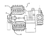
用分野、或いは用途を限定する意図のものでは決してない。図1−5にはこの発明に従っ
た独特の弁板組立体を組み込んである圧縮機装置10を示してある。この圧縮機装置10
は圧縮機ボデー12、圧縮機ヘッド14、ヘッドガスケット16、弁板組立体18、及び
弁板ガスケット20を備えている。
The following description of the preferred embodiment is illustrative only and is not intended to limit the invention, its application, or applications. 1-5 show a
1 includes a
圧縮機ボデー12には1対の圧縮シリンダ22を形成してあり、各圧縮シリンダ22内
にはピストン24を摺動可能に配置してある。各圧縮シリンダ22は吐出チャンバと吸入
チャンバとの両者に、弁板組立体18を介して連通している。
A pair of
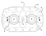
弁板組立体18は上部弁板26、下部弁板28、環状スペーサ30、複数個の内部スペ
ーサ32、及びセンタースペーサ34を備える。弁板組立体18は圧縮機装置10の吸入
チャンバと連通する1対の吸入通路36、及び圧縮機装置10の吐出チャンバと連通する
1対の吐出通路38を区画形成している。各吐出通路38は弁板組立体18の上面42と
下面44間にまたがる、放射方向内向きに傾斜した側壁40によって形成されている。傾
斜側壁40は上部弁板26から形成されている。傾斜側壁40の面46は吐出弁部材48
用の弁座を提供しており、吐出弁部材48は同弁座に対し吐出ガス圧力、及び吐出弁部材
48とブリッジ状リテーナ52との間に延在させたスプリング50によって密封係合する
ように付勢されている。
The
A valve seat is provided for the discharge valve member 48 to sealingly engage the valve seat by discharge gas pressure and a spring 50 extending between the discharge valve member 48 and the bridge-like retainer 52. Has been energized.
図示のように吐出弁部材48はその寸法と形状を吐出通路38に対し相対的に、その下
面54が弁板組立体18の下面44と実質的に同一平面上におかれるように設定されてい
る。スプリング50は、リテーナ52中に設けた溝穴56内に配置してある。吐出弁部材
48は本質的に圧力作動型のものであり、スプリング50は主として安定性を付与するた
め、及び初期シールを達成するための初期の閉鎖付勢ないし予荷重を付与するために選択
されている。この目的のために図示以外の他のタイプのスプリングも勿論、使用可能であ
る。吐出弁部材48の開放運動を制限するストップとしても機能するリテーナ52は、1
対の適当な締付け具58によって弁板組立体18に固定してある。
As shown, discharge valve member 48 is dimensioned and shaped relative to
It is secured to the
環状スペーサ30は上部弁板26と下部弁板28間に配置されており、上部弁板26及
び下部弁板28と共に吸入通路36を形成している。複数個の内部スペーサ32は図4に
示すように、各圧縮シリンダ22のまわりに位置させてある。弁板組立体18は圧縮機ボ
デー12に対し、圧縮機ヘッド14が圧縮機ボデー12に対し固定されるのと同時に固定
される。弁板組立体18は圧縮機ヘッド14と圧縮機ボデー12間で、弁板ガスケット2
0が弁板組立体18と圧縮機ボデー12間で挟持されヘッドガスケット16が弁板組立体
18と圧縮機ヘッド14間で挟持された状態の下で、挟持される。
The annular spacer 30 is disposed between the
0 is sandwiched between the
圧縮機ヘッド14、ヘッドガスケット16、弁板組立体18の上部弁板26、環状スペ
ーサ30、弁板組立体18の下部弁板28、及び弁板ガスケット20を貫通させた複数本
のボルト60を、圧縮機ボデー12に対しねじ嵌めしてある。ボルト60を締め付けるこ
とにより弁板ガスケット20が圧縮されて弁板組立体18と圧縮機ボデー12間のシール
が得られ、ヘッドガスケット16が圧縮されて弁板組立体18と圧縮機ヘッド14間のシ
ールが得られる。図示のように複数本のボルト60と弁板組立体18の環状スペーサ30
とは、圧縮機ヘッド14と弁板組立体18の外周部分に配置されている。従来技術による
と圧縮機ヘッド14、ヘッドガスケット16、弁板組立体18及び弁板ガスケット20を
貫通させ圧縮機ボデー12に対しねじ嵌めしたボルト60は、弁板ガスケット20に対し
圧縮荷重を与えるための唯一の機械的手段であった。この圧縮荷重は弁板ガスケット20
の外周部分に対しては十分なものであったけれども、弁板ガスケット20の中心部分に対
しては外周部分と対比して、該中心部分と複数本のボルト60のそれぞれとの間の間隔の
ために圧縮荷重が少な過ぎた。
The
Is disposed on the outer peripheral portion of the
Is sufficient for the outer peripheral portion of the valve plate gasket 20, but the distance between the central portion and each of the plurality of bolts 60 is smaller than the outer peripheral portion of the valve plate gasket 20. Therefore, the compression load was too small.
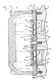
この発明はセンタースペーサ34を追加することによって弁板ガスケット20の圧縮特
性、したがって同ガスケット20の性能と耐久性を改善するものである。センタースペー
サ34は1個の圧縮シリンダ22の幾何学的中心と隣接する圧縮シリンダ22の幾何学的
中心とを通る直線上の位置で、弁板組立体18のほぼ幾何学的中心に配置してある。これ
によってセンタースペーサ34は、弁板組立体18の長さ及び幅の両者のほぼ中間に位置
している。センタースペーサ34は上部弁板26と下部弁板28間に配置され、下部弁板
28に形成した穴62に支承されている。下部弁板28中の穴62に支承させる構造を図
示したが、所望の場合には穴62を上部弁板26に設けてセンタースペーサ34を図示の
場合とは上下逆にすることもできる。センタースペーサ34には貫通孔64を形成してあ
り、同貫通孔64は上部弁板26を貫通する孔66と整列位置している。上部弁板26の
孔66とセンタースペーサ34の貫通孔64とを通してセンターボルト68を設けて、同
ボルト68を圧縮機ボデー12に対しねじ嵌めしてある。センターボルト68を締め付け
ることによって弁板ガスケット20の中心部で該弁板ガスケット20に対する追加の圧縮
荷重が与えられて弁板ガスケット20の圧縮度が増し、弁板ガスケット20の全体に対し
てより大きなクランプ荷重が生ぜしめられて、同ガスケット20の性能とシール機能の耐
久性が改善される。
The present invention improves the compression characteristics of the valve plate gasket 20 and therefore the performance and durability of the gasket 20 by adding a center spacer 34. The center spacer 34 is disposed substantially at the geometric center of the
弁板組立体18にはさらに環状の弁座70が形成され、また側壁40にはその端で環状
の弁座72が形成されている。これらの弁座70,72間に吸入通路36を配置してある
。
The
側壁40の弁座72は弁板組立体18の弁座70と同一平面上に位置させてある。環状
リングの形式の吸入リード弁部材76がその閉鎖位置において側壁40の弁座72と弁板
組立体18の弁座70とに対し密封的に係合して、圧縮シリンダ22から吸入通路36中
への流体通路を遮断する。吸入リード弁部材76には中央の開口78を、圧縮シリンダ2
2と吐出弁部材48の下面54間の直接の流体連通を許容するように吐出通路38と同心
的に配置して設けてある。吸入リード弁部材76は一直径線上に位置し放射方向外向きに
延出する1対のタブ80も、有する。1個のタブ80は吸入リード弁部材76を、1対の
駆動植込みボルト82を用いて弁板組立体18に対し固定するために用いられている。
The valve seat 72 on the side wall 40 is flush with the valve seat 70 on the
It is provided concentrically with the
吸入行程において圧縮シリンダ22内でピストン24が弁板組立体18から遠ざかるに
つれ、圧縮シリンダ22と吸入通路36間の圧力差によって吸入リード弁部材76が圧縮
シリンダ22に関し相対的に内向きに開放位置(図3に破線図示)へと屈折し、それによ
って吸入通路36から圧縮シリンダ22内へのガス流れが弁座70,72間で可能とされ
る。吸入リード弁部材76のタブ80のみが圧縮シリンダ22の側壁を越えて放射方向外
向きに延出していることから吸入流体流れは圧縮シリンダ22内へ容易に、吸入リード弁
部材76の実質的に全内外周まわりで流入する。ピストン24の圧縮行程が開始するにつ
れ吸入リード弁部材76は、弁座70及び弁座72との密封係合状態へともたらされる。
圧縮シリンダ22内の圧力が吐出通路38内の圧力及びスプリング50により及ぼされる
力を越えることによって、吐出弁部材48が開放し始める。圧縮ガスは中央の開口78を
介し、吐出弁部材48を通して吐出通路38中へともたらされる。弁板組立体18と吸入
リード弁部材76とを同心的に配置したことによって圧縮シリンダ22上にある実質的に
全有効面積を、吸入及び吐出弁作用及びポート開閉作用のために利用でき、それによって
圧縮シリンダ22中への、そして同シリンダ22からの最大限のガス流れが可能となって
いる。
As the piston 24 moves away from the
When the pressure in
圧縮シリンダ22内でのピストン24の連続した往復動によって吸入リード弁部材76
と吐出弁部材48は、これらの弁部材の開放位置と閉鎖位置との間で連続的に動かされる
。圧縮機ボデー12は吸入リード弁部材76の自由端に隣接する圧縮シリンダ22の外縁
において、吸入リード弁部材76がそれに対し湾曲できる補助的な面を付与するための湾
曲部分84を含んでおり、それによって自由端のタブ80内で発生する曲げ応力が有意義
に減少される。
The continuous reciprocation of the piston 24 in the
And the discharge valve member 48 are continuously moved between an open position and a closed position of these valve members. The
図6にはこの発明の他の実施例に従った圧縮機装置110を示してある。図6に示す実
施例は図3に示す実施例と、前記センターボルト68がセンターボルト168に置き換え
られている点を除いて同一である。センターボルト68は弁板組立体18と弁板ガスケッ
ト20を貫通させ、圧縮機ボデー12に対しねじ込まれていた。これに対し図6に示すセ
ンターボルト168は圧縮機ヘッド14、弁板組立体18及び弁板ガスケット20を貫通
させ、圧縮機ボデー12に対しねじ込まれている。追加の圧縮荷重を加えるために圧縮機
ヘッド14には延長部170を付加してあり、センターボルト168は該延長部170内
を通過させてある。圧縮機装置110の動作、機能及び特徴は、圧縮機装置10について
前述したのと同一である。
FIG. 6 shows a
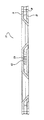
図7にはこの発明の別の実施例に従った弁板組立体118を示してある。弁板組立体1
18は前記弁板組立体18と、前記センタースペーサ34がセンタースペーサ134に置
き換えられている点を除いて同一である。センタースペーサ134は前記センタースペー
サ34と同一の位置、つまり弁板組立体118のほぼ幾何学的中心に配置してある。これ
によってセンタースペーサ134は弁板組立体118の長さ及び幅の両者のほぼ中間、つ
まり図4に示したセンタースペーサ34と同一の位置におかれている。センタースペーサ
134は上部弁板26と下部弁板28間に配置され、上部弁板26に形成した穴162に
支承されている。上部弁板26中の穴162に支承させる構造を図示したが、所望の場合
には穴162を下部弁板28に設けてセンタースペーサ134を図示の場合とは上下逆に
することもできる。
FIG. 7 shows a
センタースペーサ134が剛性部材であることからセンターボルト68又は168は設
けてなく、弁板ガスケット20はその中心部分で、センターボルトの締め付けによる追加
の圧縮を何ら受けない。その代わりに弁板ガスケット20の中心部分に対する追加の圧縮
荷重は、図6に示した延長部170に類似したセンターリブ(図示せず)を追加して設け
ることによって、そして弁板組立体118の上方に位置するガス吐出チャンバ内の圧縮ガ
スからする吐出圧力によって、加えられる。吐出圧力の圧縮ガスは上部弁板26に対し荷
重を加え、この荷重はセンタースペーサ134を介して下部弁板28に対し直接に伝えら
れる。またボルト60の締め付けによってセンターリブ(図示せず)を介し上部弁板26
に対し荷重が加わり、この荷重もセンタースペーサ134を介して下部弁板28に対し直
接に伝えられる。下部弁板28に対し加わる荷重は次に弁板ガスケット20に加わって、
弁板ガスケット20の中心で該弁板ガスケット20のための追加の圧縮荷重が付与され、
弁板ガスケット20の圧縮度が増して弁板ガスケット20の全体にわたりより大きなクラ
ンプ力が生ぜしめられ、該弁板ガスケット20の性能とシール機能の耐久度が改善される
。センタースペーサ134を設けていなかった従来構造では、上部弁板26に加わる圧力
荷重が下部弁板28に対し直接には伝えられなかった。
Because the
, And this load is also transmitted directly to the
An additional compressive load for the valve plate gasket 20 is applied at the center of the valve plate gasket 20,
The degree of compression of the valve plate gasket 20 is increased, causing a greater clamping force over the entire valve plate gasket 20, and the performance of the valve plate gasket 20 and the durability of the sealing function are improved. In the conventional structure without the
以上に述べた実施例についての説明は単に例示的なものであり、この発明の要旨とする
ところを外れることのない変形例はこの発明の範囲内であることを意図したものである。
そのような変形例を、この発明の範囲から逸脱するものと見做すべきではない。
The description of the embodiments described above is merely illustrative, and modifications that do not depart from the gist of the present invention are intended to be within the scope of the present invention.
Such modifications should not be deemed to depart from the scope of the present invention.
10,110 圧縮機装置
12 圧縮機ボデー
14 圧縮機ヘッド
16 ヘッドガスケット
18,118 弁板組立体
20 弁板ガスケット
22 圧縮シリンダ
26 上部弁板
28 下部弁板
30 環状スペーサ
34,134 センタースペーサ
60 ボルト
62 穴
64 貫通孔
66 孔
68,168 センターボルト
162 穴
170 延長部
10,110
Claims (12)
この圧縮機ボデーに取り付けられた圧縮機ヘッド、及び
これらの圧縮機ヘッドと圧縮機ボデー間に配置された弁板組立体、
を備えた冷凍用圧縮機において、上記弁板組立体が、
上部弁板、
下部弁板、
これらの上下の弁板間に配置され上記した第1及び第2の圧縮シリンダを取り囲む環状
スペーサ、及び
上記した上下の弁板間に配置されたセンタースペーサであって、上記した第1及び第2
の圧縮シリンダ間に位置させてあるセンタースペーサ、
を備えている冷凍用圧縮機。 A compressor body forming a first compression cylinder and a second compression cylinder;
A compressor head mounted on the compressor body, and a valve plate assembly disposed between the compressor head and the compressor body;
In the refrigeration compressor provided with, the valve plate assembly,
Upper valve plate,
Lower valve plate,
An annular spacer disposed between the upper and lower valve plates and surrounding the first and second compression cylinders, and a center spacer disposed between the upper and lower valve plates,
A center spacer located between the compression cylinders of
Refrigeration compressor equipped with.
機シリンダの幾何学的中心とを結ぶ直線上に配置してある請求項1の冷凍用圧縮機。 2. The refrigerating compressor according to claim 1, wherein the center spacer is disposed on a straight line connecting a geometric center of the first compressor cylinder and a geometric center of the second compressor cylinder.
又は2の冷凍用圧縮機。 2. The valve of claim 1, wherein the center spacer is disposed substantially at a geometric center of the valve plate assembly.
Or the compressor for refrigeration of 2.
貫通孔を形成してある請求項1の冷凍用圧縮機。 2. The refrigerating compressor according to claim 1, wherein a through hole is formed in the center spacer so as to be concentric with a hole passing through the upper valve plate and a hole passing through the lower valve plate.
ボデーに対しねじ込んであるボルトを設けてある請求項5の冷凍用圧縮機。 6. The refrigerating compressor according to claim 5, further comprising a bolt which is screwed into the compressor body through the hole of the upper valve plate, the through hole of the center spacer, and the hole of the lower valve plate.
機シリンダの幾何学的中心とを結ぶ直線上に配置してある請求項6の冷凍用圧縮機。 7. The refrigerating compressor according to claim 6, wherein the center spacer is arranged on a straight line connecting a geometric center of the first compressor cylinder and a geometric center of the second compressor cylinder.
又は7の冷凍用圧縮機。 7. The valve of claim 6, wherein the center spacer is disposed substantially at the geometric center of the valve plate assembly.
Or the compressor for refrigeration of 7.
用圧縮機。 2. The refrigerating compressor according to claim 1, wherein said center spacer is supported in a hole formed in said upper valve plate.
用圧縮機。 2. The refrigerating compressor according to claim 1, wherein said center spacer is supported in a hole formed in said lower valve plate.
機シリンダの幾何学的中心とを結ぶ直線上に配置してある請求項9又は10の冷凍用圧縮
機。 11. The refrigerating compressor according to claim 9, wherein the center spacer is arranged on a straight line connecting a geometric center of the first compressor cylinder and a geometric center of the second compressor cylinder. .
,10又は11の冷凍用圧縮機。
10. The valve of claim 9, wherein the center spacer is disposed substantially at a geometric center of the valve plate assembly.
, 10 or 11 refrigeration compressor.
Applications Claiming Priority (1)
| Application Number | Priority Date | Filing Date | Title |
|---|---|---|---|
| US10/374,385 US7040877B2 (en) | 2003-02-25 | 2003-02-25 | Compressor valve plate |
Publications (1)
| Publication Number | Publication Date |
|---|---|
| JP2004257374A true JP2004257374A (en) | 2004-09-16 |
Family
ID=32771444
Family Applications (1)
| Application Number | Title | Priority Date | Filing Date |
|---|---|---|---|
| JP2003375063A Pending JP2004257374A (en) | 2003-02-25 | 2003-11-05 | Compressor for refrigeration |
Country Status (10)
| Country | Link |
|---|---|
| US (2) | US7040877B2 (en) |
| EP (1) | EP1452735B1 (en) |
| JP (1) | JP2004257374A (en) |
| KR (1) | KR100991710B1 (en) |
| CN (2) | CN100480509C (en) |
| AR (1) | AR041844A1 (en) |
| BR (1) | BR0304779B1 (en) |
| CA (1) | CA2444082C (en) |
| MX (1) | MXPA04001581A (en) |
| TW (1) | TWI223052B (en) |
Cited By (1)
| Publication number | Priority date | Publication date | Assignee | Title |
|---|---|---|---|---|
| WO2007049554A1 (en) * | 2005-10-25 | 2007-05-03 | Sanden Corporation | Reciprocating fluid machine |
Families Citing this family (18)
| Publication number | Priority date | Publication date | Assignee | Title |
|---|---|---|---|---|
| US7040877B2 (en) * | 2003-02-25 | 2006-05-09 | Copeland Corporation | Compressor valve plate |
| BRPI0505902A (en) * | 2005-12-22 | 2007-09-25 | Brasil Compressores Sa | compact compressor |
| US8197240B2 (en) * | 2007-10-02 | 2012-06-12 | Emerson Climate Technologies, Inc. | Compressor having improved valve plate |
| CN101915327A (en) * | 2010-08-25 | 2010-12-15 | 吕文孝 | Control valve for heat flow instrument |
| DE102015015177A1 (en) | 2014-12-22 | 2016-06-23 | Gea Bock Gmbh | compressor |
| US10436187B2 (en) | 2015-10-29 | 2019-10-08 | Emerson Climate Technologies, Inc. | Cylinder head assembly for reciprocating compressor |
| US11105326B2 (en) | 2016-05-07 | 2021-08-31 | Emerson Climate Technologies, Inc. | Single piece valve plate assembly for a reciprocating compressor |
| US10328771B2 (en) | 2016-06-30 | 2019-06-25 | Emerson Climated Technologies, Inc. | System and method of controlling an oil return cycle for a refrigerated container of a vehicle |
| US10315495B2 (en) | 2016-06-30 | 2019-06-11 | Emerson Climate Technologies, Inc. | System and method of controlling compressor, evaporator fan, and condenser fan speeds during a battery mode of a refrigeration system for a container of a vehicle |
| US10300766B2 (en) | 2016-06-30 | 2019-05-28 | Emerson Climate Technologies, Inc. | System and method of controlling passage of refrigerant through eutectic plates and an evaporator of a refrigeration system for a container of a vehicle |
| US10569620B2 (en) | 2016-06-30 | 2020-02-25 | Emerson Climate Technologies, Inc. | Startup control systems and methods to reduce flooded startup conditions |
| US10828963B2 (en) | 2016-06-30 | 2020-11-10 | Emerson Climate Technologies, Inc. | System and method of mode-based compressor speed control for refrigerated vehicle compartment |
| US10532632B2 (en) | 2016-06-30 | 2020-01-14 | Emerson Climate Technologies, Inc. | Startup control systems and methods for high ambient conditions |
| US10414241B2 (en) | 2016-06-30 | 2019-09-17 | Emerson Climate Technologies, Inc. | Systems and methods for capacity modulation through eutectic plates |
| US10562377B2 (en) | 2016-06-30 | 2020-02-18 | Emerson Climate Technologies, Inc. | Battery life prediction and monitoring |
| EP3327287A1 (en) * | 2016-11-23 | 2018-05-30 | Almatec Maschinenbau GmbH | Membrane pump |
| CN110905769B (en) * | 2019-12-11 | 2021-10-26 | 珠海格力节能环保制冷技术研究中心有限公司 | Exhaust valve assembly, compressor and household appliance |
| KR20210105565A (en) * | 2020-02-19 | 2021-08-27 | 한온시스템 주식회사 | Scroll compressor |
Family Cites Families (29)
| Publication number | Priority date | Publication date | Assignee | Title |
|---|---|---|---|---|
| US886045A (en) * | 1906-03-06 | 1908-04-28 | Herman J Ehrlich | Valve. |
| US1852033A (en) * | 1925-11-25 | 1932-04-05 | Frigidaire Corp | Check valve |
| US1834589A (en) * | 1927-12-29 | 1931-12-01 | Sullivan Machinery Co | Valve mechanism |
| NL108432C (en) * | 1959-03-23 | 1900-01-01 | ||
| AT350702B (en) * | 1976-10-06 | 1979-06-11 | Enfo Grundlagen Forschungs Ag | LAMELLA VALVE FOR PISTON COMPRESSORS |
| US4368755A (en) * | 1978-12-20 | 1983-01-18 | Copeland Corporation | Valve assembly |
| US4445534A (en) * | 1980-12-23 | 1984-05-01 | Copeland Corporation | Valve assembly |
| US4478243A (en) * | 1978-12-20 | 1984-10-23 | Copeland Corporation | Valve assembly |
| US4543989A (en) * | 1981-11-04 | 1985-10-01 | Copeland Corporation | Discharge valve assembly for refrigeration compressors |
| US4548234A (en) * | 1981-11-04 | 1985-10-22 | Copeland Corporation | Discharge valve assembly |
| US4470774A (en) * | 1981-11-04 | 1984-09-11 | Copeland Corporation | Valve plate assembly for refrigeration compressors |
| US4469126A (en) * | 1981-11-04 | 1984-09-04 | Copeland Corporation | Discharge valve assembly for refrigeration compressors |
| US4643139A (en) * | 1983-07-20 | 1987-02-17 | Hargreaves Bernard J | Reed valves for internal combustion engines |
| US4642037A (en) * | 1984-03-08 | 1987-02-10 | White Consolidated Industries, Inc. | Reed valve for refrigeration compressor |
| US4696263A (en) * | 1985-07-12 | 1987-09-29 | Performance Industries, Inc. | Reed valves for internal combustion engines |
| US4729402A (en) * | 1986-08-01 | 1988-03-08 | Copeland Corporation | Compressor valve noise attenuation |
| DE3721464A1 (en) * | 1987-06-30 | 1989-01-12 | Wabco Westinghouse Fahrzeug | STOP FOR A COMPRESSOR LAMBER VALVE |
| US5022833A (en) * | 1989-12-06 | 1991-06-11 | Tecumseh Products Company | Single piece gasket valve plate assembly |
| US5016669A (en) * | 1990-06-04 | 1991-05-21 | Dresser-Rand Company | Valve assembly |
| BR9002787A (en) * | 1990-06-08 | 1991-12-10 | Brasil Compressores Sa | VALVE FOR HERMETIC COMPRESSOR |
| EP0491026B1 (en) * | 1990-07-10 | 1995-03-01 | Westonbridge International Limited | Valve, method for producing said valve and micropump incorporating said valve |
| US5213487A (en) * | 1991-06-26 | 1993-05-25 | Holset Engineering Company, Inc. | Ring valve type air compressor with deformable ring valves |
| US5213125A (en) * | 1992-05-28 | 1993-05-25 | Thomas Industries Inc. | Valve plate with a recessed valve assembly |
| US5934305A (en) * | 1996-09-12 | 1999-08-10 | Samsung Electronics Co., Ltd. | Method of manufacturing a reciprocating compressor |
| US6044832A (en) | 1998-08-10 | 2000-04-04 | Piersons, Jr.; Donald W. | Fall away arrow rest assembly |
| US6044862A (en) * | 1999-02-16 | 2000-04-04 | Copeland Corporation | Compressor reed valve |
| US6164334A (en) * | 1999-04-27 | 2000-12-26 | Copeland Corporation | Reed valve retention |
| JP2001032774A (en) | 1999-07-22 | 2001-02-06 | Mitsubishi Electric Corp | Valve device of reciprocating coolant compressor |
| US7040877B2 (en) * | 2003-02-25 | 2006-05-09 | Copeland Corporation | Compressor valve plate |
-
2003
- 2003-02-25 US US10/374,385 patent/US7040877B2/en not_active Expired - Lifetime
- 2003-10-07 CA CA2444082A patent/CA2444082C/en not_active Expired - Fee Related
- 2003-10-08 TW TW092127993A patent/TWI223052B/en not_active IP Right Cessation
- 2003-10-08 KR KR1020030069857A patent/KR100991710B1/en active IP Right Grant
- 2003-10-09 EP EP03256361.1A patent/EP1452735B1/en not_active Expired - Fee Related
- 2003-10-28 BR BRPI0304779-2A patent/BR0304779B1/en not_active IP Right Cessation
- 2003-10-28 AR ARP030103932A patent/AR041844A1/en active IP Right Grant
- 2003-11-05 JP JP2003375063A patent/JP2004257374A/en active Pending
- 2003-12-09 CN CNB200610092497XA patent/CN100480509C/en not_active Expired - Fee Related
- 2003-12-09 CN CNB2003101202214A patent/CN1270088C/en not_active Expired - Lifetime
-
2004
- 2004-02-20 MX MXPA04001581A patent/MXPA04001581A/en active IP Right Grant
-
2006
- 2006-04-07 US US11/400,809 patent/US7618244B2/en active Active
Cited By (1)
| Publication number | Priority date | Publication date | Assignee | Title |
|---|---|---|---|---|
| WO2007049554A1 (en) * | 2005-10-25 | 2007-05-03 | Sanden Corporation | Reciprocating fluid machine |
Also Published As
| Publication number | Publication date |
|---|---|
| TWI223052B (en) | 2004-11-01 |
| AU2004200755A1 (en) | 2004-09-09 |
| CN1525067A (en) | 2004-09-01 |
| TW200416372A (en) | 2004-09-01 |
| CA2444082C (en) | 2010-12-21 |
| CN100480509C (en) | 2009-04-22 |
| BR0304779A (en) | 2005-05-17 |
| US20040166006A1 (en) | 2004-08-26 |
| US7618244B2 (en) | 2009-11-17 |
| CA2444082A1 (en) | 2004-08-25 |
| US20060177331A1 (en) | 2006-08-10 |
| US7040877B2 (en) | 2006-05-09 |
| CN1896514A (en) | 2007-01-17 |
| KR100991710B1 (en) | 2010-11-03 |
| AR041844A1 (en) | 2005-06-01 |
| EP1452735A3 (en) | 2006-05-17 |
| KR20040076567A (en) | 2004-09-01 |
| CN1270088C (en) | 2006-08-16 |
| MXPA04001581A (en) | 2004-08-30 |
| EP1452735A2 (en) | 2004-09-01 |
| EP1452735B1 (en) | 2018-12-05 |
| BR0304779B1 (en) | 2012-03-20 |
Similar Documents
| Publication | Publication Date | Title |
|---|---|---|
| JP2004257374A (en) | Compressor for refrigeration | |
| US5169296A (en) | Air driven double diaphragm pump | |
| JPH0353477B2 (en) | ||
| US5022832A (en) | Ring valve type air compressor | |
| JPS5912907B2 (en) | Compressa | |
| KR960031793A (en) | compressor | |
| JP2002371963A (en) | Compressor piston with reduced discharge clearance | |
| US4834631A (en) | Separator and biasing plate | |
| KR910018672A (en) | Refrigeration compressor | |
| EP0522745B1 (en) | A ring valve assembly for a reciprocating fluid pump | |
| JPH0154554B2 (en) | ||
| CA1037926A (en) | Valve plate having improved suction gas flow path | |
| JP2688809B2 (en) | air compressor | |
| KR20040076569A (en) | Compressor discharge valve retainer | |
| JPH0418148B2 (en) | ||
| US20230057129A1 (en) | Alternative compressor head arrangement | |
| JP2001032774A (en) | Valve device of reciprocating coolant compressor | |
| US20190285185A1 (en) | Clamping Arrangement for Valves in Reciprocating Compressor Cylinders | |
| CN100572808C (en) | The compressor that is used for gas tight seal formula small-sized refrigerator | |
| JP2000087857A (en) | Fluid machine | |
| JPH0295783A (en) | Discharge valve system for compressor | |
| KR200184074Y1 (en) | Suction gasket for hermetic compressor | |
| AU2002351744A1 (en) | Reciprocating compressor | |
| US20110064590A1 (en) | Valve Arrangement for Peripherally Pivoted Oscillating Vane Machine | |
| KR20030042817A (en) | Cylinder head for compressor |