JP2004257312A - Valve timing controller - Google Patents
Valve timing controller Download PDFInfo
- Publication number
- JP2004257312A JP2004257312A JP2003049244A JP2003049244A JP2004257312A JP 2004257312 A JP2004257312 A JP 2004257312A JP 2003049244 A JP2003049244 A JP 2003049244A JP 2003049244 A JP2003049244 A JP 2003049244A JP 2004257312 A JP2004257312 A JP 2004257312A
- Authority
- JP
- Japan
- Prior art keywords
- lock
- phase
- engine
- rotation
- control
- Prior art date
- Legal status (The legal status is an assumption and is not a legal conclusion. Google has not performed a legal analysis and makes no representation as to the accuracy of the status listed.)
- Granted
Links
Images


Classifications
-
- Y—GENERAL TAGGING OF NEW TECHNOLOGICAL DEVELOPMENTS; GENERAL TAGGING OF CROSS-SECTIONAL TECHNOLOGIES SPANNING OVER SEVERAL SECTIONS OF THE IPC; TECHNICAL SUBJECTS COVERED BY FORMER USPC CROSS-REFERENCE ART COLLECTIONS [XRACs] AND DIGESTS
- Y02—TECHNOLOGIES OR APPLICATIONS FOR MITIGATION OR ADAPTATION AGAINST CLIMATE CHANGE
- Y02T—CLIMATE CHANGE MITIGATION TECHNOLOGIES RELATED TO TRANSPORTATION
- Y02T10/00—Road transport of goods or passengers
- Y02T10/10—Internal combustion engine [ICE] based vehicles
- Y02T10/12—Improving ICE efficiencies
Landscapes
- Valve Device For Special Equipments (AREA)
- Output Control And Ontrol Of Special Type Engine (AREA)
- Combined Controls Of Internal Combustion Engines (AREA)
Abstract
Description
【0001】
【発明の属する技術分野】
本発明は、クランクシャフトに対して同期回転する駆動側回転部材と、前記駆動側回転部材に対して同軸状に配置され、カムシャフトとともに回転する従動側回転部材とを備え、
油圧制御により前記駆動側回転部材と前記従動側回転部材との相対回転位相が調整される回転位相調整機構と、前記相対回転位相をロック位相において拘束する回転位相拘束機構とを備え、
前記ロック位相が最遅角位相と最進角位相との中間位相域に設定され、
前記回転位相拘束機構が、油圧制御により前記両回転部材の相対回転を許容するロック解除姿勢と、拘束するロック姿勢との間で姿勢変更可能とされる弁開閉時期制御装置に関する。
【0002】
【従来の技術】
この種の弁開閉時期制御装置は、駆動側回転部材と従動側回転部材との相対回転位相を流体圧室内に設けられたベーンの回転位置制御により変更・設定可能とされており、内燃機関の運転状態に対応して相対回転位相を適切に設定することで好適な運転状態を達成する。
【0003】
簡単に、この種の開閉時期制御装置の基本構造を説明すると、図2、3に示すように、ベーン5は流体圧室40を進角室43と遅角室42とに仕切る。さらに、ベーン5は、従動側回転部材である内部ロータ1の径方向に設けられるベーン溝41に出退移動可能に収納され、内部ロータ1に収納されているベーンスプリング51により、駆動側回転部材である外部ロータ2の流体圧室内壁面wに付勢されている。
【0004】
この種の弁開閉時期制御装置にあって、エンジン停止時に、両ロータの相対回転位相をロック位相に導き、ロックがかかった状態で次回のエンジン始動を開始するように制御を行なうものがある。
この種の制御は、弁開閉時期制御装置に設けられる進角室、遅角室内の油圧制御により、相対回転位相をイグニッションスイッチオフ(以降IG−OFFと記載する)後、油圧が残存している短時間に、前記相対回転位相をロック位相に制御するもの(以下の前者の技術)と、エンジン停止時のエンジン逆回転を利用するもの(以下の後者の技術)とがある。
【0005】
前者の技術は、中間ロックを対象とするものであり、相対回転位相を何らかの手段で検出し、ロック位相に回転位相を近づける油圧制御を進角室・遅角室に対する油圧の制御を実行して、油圧制御によりロック位相に到達するようにする。
(特許文献1)。
【0006】
後者に属する技術としては、比較的古い技術で、中間ロック構造を採用しないもので、クランクシャフトに接続される電動機を利用してエンジンの逆転を起こさせるもの(特許文献2)、比較的新しいもので、中間ロック構造を採用しつつ、エンジンへの吸入空気量を増加させて、エンジン停止に伴った、その最終段階で、エンジン逆転を発生させるもの(特許文献3)がある。
【0007】
後者の技術にあっては、回転位相拘束機構であるロック機構に関して、エンジン停止後にはロックがかかりうる状態にロック機構が設定される必要(ロック機構にロック体を備え、ロック姿勢において、ロック体がロック溝に侵入してロックがかかる構造のものにあっては、ロック溝から油圧が解除されている状態が確立されている必要)があるが、これら従来技術にあっては、ロック溝への油圧の供給系統が、ベーンの相対移動を起こすための油圧系統と共通とされていた。
【0008】
【特許文献1】
特開2001−50063号公報
【特許文献2】
特開2002−266669号公報
【特許文献3】
特開2000−320356号公報
【0009】
【発明が解決しようとする課題】
上記ベーンに対する油圧制御を施して、停止ロックをかける技術では、IG−OFF後も、相対回転位相を検知し、停止時に確実にロック位相まで制御する手法を施したり、停止までの間で、複雑な油圧制御を実行して、停止時に確実にロック位相まで到達するように制御する必要がある。
しかしながら、この種、エンジン回転に依存して発生する油圧を利用する場合は、IG−OFF後、僅かな時間に残存する油圧を用いて、IG−OFF時の相対回転位相からロック位相近傍まで、もしくは、ロック位相まで制御を施すことが必要となるため、確実なロックの保証を得るという点で信頼性に欠ける。
【0010】
一方、後者の技術にあっては、従来、回転位相調整のために設けられている進角室、あるいは遅角室への油圧供給系統から、ロック溝への油圧の供給を受けるものとされていたため、ロック溝からの油の排出が遅れた場合、ロック機構自体がロック姿勢に移行することができず、この点で問題があった。
【0011】
本発明の目的は、IG−OFF後に、相対回転位相をロック位相に移行させ、所謂、停止ロックをかける場合に、そのロックを信頼性良く、確実にかけることが可能な開閉時期制御装置を得ることにある。
【0012】
【課題を解決するための手段】
上記目的を達成するための、本願に係る、
クランクシャフトに対して同期回転する駆動側回転部材と、前記駆動側回転部材に対して同軸状に配置され、カムシャフトとともに回転する従動側回転部材とを備え、
油圧制御により前記駆動側回転部材と前記従動側回転部材との相対回転位相が調整される回転位相調整機構と、前記相対回転位相をロック位相において拘束する回転位相拘束機構とを備え、
前記ロック位相が最遅角位相と最進角位相との中間位相域に設定され、
前記回転位相拘束機構が、油圧制御により前記両回転部材の相対回転を許容するロック解除姿勢と、拘束するロック姿勢との間で姿勢変更可能とされる弁開閉時期制御装置弁開閉時期制御装置の特徴構成は、請求項1に記載されているように、前記回転位相調整機構に対する油圧系統と、前記回転位相拘束機構に対する油圧系統とが、独立に油圧供給を受ける構成を有し、
エンジン停止指令に従って、前記回転位相拘束機構を、前記ロック解除姿勢から前記ロック姿勢への移行動作可能なロック待機状態とするロック制御手段と、エンジンを逆回転制御するエンジン制御手段とを備え、
前記ロック制御手段により実現される前記ロック待機状態において、前記エンジン制御手段により実現されるエンジン逆回転により、前記回転位相拘束機構の前記ロック姿勢が確保されることにある。
【0013】
この構成の弁開閉時期制御装置は、ロック制御手段とエンジン制御手段とが備えられ、IG−OFF後に、前記ロック手段が、回転位相拘束機構を、ロック解除姿勢から前記ロック姿勢への移行動作可能なロック待機状態とする。
従って、この制御手段の働きにより、回転位相拘束機構は、回転位相がロック位相に到達した段階において、ロック解除姿勢からロック姿勢への姿勢変更を容易、且つ確実に実行できるようになる。
この状態において、本願の弁開閉時期制御装置にあっては、回転位相調整機構に対する油圧系統と、回転位相拘束機構に対する油圧系統とが、独立に油圧供給を受ける構成とされているため、回転位相調整機構側の影響を受けることもない。従って、ロックに対する信頼性が高まる。
【0014】
一方、エンジン制御手段は、エンジン逆回転を起こさせるように制御することで、この逆回転に起因して、回転位相をロック位相側に移行させることが可能となり、結果的に、確実なロックを実現できる。
【0015】
さて、上記構成にあって、請求項2に記載されているように、エンジン停止指令以降、エンジンの逆回転以前に、前記回転位相調整機構を働かせて、相対回転位相を最遅角位相とロック位相との間のロック待機位相とする位相制御手段を備えることが好ましい。
【0016】
上記したように、エンジンの停止操作は、エンジンが正転している場合、基本的には相対回転位相を遅角側に進める方向に働き、エンジン逆転が発生する段階において、回転位相が、最遅角位相とロック位相との間に到達している可能性は高いが、この構成のように、位相制御手段を備えて、IG−OFF段階で、一旦、遅角側(最遅角位相とロック位相との間)に、回転位相を移行させておき、エンジンの逆転を起こさせて、ロック位相側への移動(進角移動)を起こさせることで、確実なロックをかけることができる。
この制御は、ロック位相が特定されているため、所定時間、あるいはそれ以下の所定時間の遅角側への移動制御とすることができる。
ここで、エンジンが逆転する時点にあっては、油圧も低下しており、ロック解除維持ができない状況に到達しているため、確実にロックがかかることとなる。
【0017】
さて、エンジン制御手段による制御としては、請求項3に記載されているようなエンジン吸入空気量の増大制御、請求項4に記載されているような、クランクシャフトを逆回転可能な電動機に対するクランクシャフトを逆回転させる制御とすることができる。
この種の制御は、従来型の機器構成において、その制御プログラムを、IG−OFF入力との関連において、適切に設定することで、容易に実現できる。
結果、従来型の構造を踏襲したまま、停止ロックを確実に実現できる。
【0018】
さて、これまで説明してきた構成において、請求項5に記載されているように、前記回転位相拘束機構が、前記駆動側回転部材と前記従動側回転部材とのいずれか一方の回転部材側から他方の回転部材内に突入して、両回転部材の相対回転を拘束するロック体と、前記他方の回転部材に設けられて前記ロック体と係合するロック溝とを備えて構成され、
前記エンジンの逆回転に伴って、前記ロック体が前記ロック溝上まで近接移動されて前記ロック溝内に突入するに、前記近接移動経路にある前記他方の回転部材表面位置が、前記ロック溝を越えた側の前記近接移動経路の延長経路にある他方の回転部材表面位置より溝の内側に設定され、前記ロック体に対する案内路が設けられていることが好ましい。
【0019】
この構成を採用することで、遅角側からロック体が他の回転部材表面に当接しながら、ロック溝上まで移動してきた段階で、ロック体の先端が、ロック溝側壁に当たり、ロック体を溝内への移動へと方向づけることで、確実なロックを実現できる。
【0020】
【発明の実施の形態】
本発明の実施の形態について、図1〜図8に基づいて説明する。
図3、4及び7は、図2におけるA−A断面の概略を一部に使用した機能説明図面である。
【0021】
〔本願のエンジン制御システムの概略構成〕
このシステムは、エンジン100に燃料及び燃焼用空気を供給する吸気系統、及びエンジンからの排気を排出するための排気系統を有して構成されるとともに、本願が対象とするバルブタイミング調整用の弁開閉時期制御装置本体VVTを備えて構成される。このシステムの全体は、弁開閉時期制御装置本体VVTに対するコントローラとしても働く、電子制御ユニットECUによる動作制御を受ける。
【0022】
エンジンまわりの機械的構成から説明すると、図1に示すように、内燃機関であるエンジン100の吸気管101に、上流側から、吸入空気量を検出するエアフローメータ103、スロットルバルブ104、サージタンク105が記載順に設けられており、吸入された空気が、エンジン100に送り込まれるように構成されている。
【0023】
前記スロットルバルブ104に対して、これをバイパスするバイパス通路104aが設けられ、このバイパス通路104aに、スロットルバルブ104をバイパスする吸入空気量を調整するバイパス空気量調整弁としてアイドルスピードコントロールバルブ(以降ISCバルブ)104bが設けられている。
従って、ISCバルブ104bを使用して、エンジン停止時に、エンジン100を逆転させることが可能となっている。
【0024】
前記サージタンク105の下手には、エンジン100の各気筒に空気を導入する吸気マニホールド106が設けられ、各気筒の吸気ポート近傍に、それぞれ燃料を噴射する燃料噴射弁107が取り付けられている。
各気筒のシリンダヘッドには、点火プラグ108が取り付けられている。
【0025】
弁開閉時期制御装置本体VVTは、前記電子制御ユニットECUからの指令を受けてオイルコントロールバルブOCVが働き、弁開閉時期制御装置本体VVTの動作が制御される。
前記電子制御ユニットECUには、イグニッションスイッチ(IG/SW)
109、スロットル開度センサ110等からの動作指令が入力されるように構成されている。
さらに、カムシャフトの位相を検知するカム角センサ111、クランクシャフトの位相を検知するクランク角センサ112、エンジンオイルの温度を検知する油温センサ113、クランクシャフトの回転数(エンジン回転数)を検知する回転数センサ114、その他の車速センサ、エンジンの冷却水温センサ、又は、スロット開度センサ等の各種センサの検知信号が入力される。
この電子制御ユニットECUは、オイルコントロールバルブOCV、ISCバルブ104b、燃料噴射弁107、点火プラグ108等への動作指令を出力する。図9、10に示す別実施の形態にあっては、電動機9に対する動作指令をも出すこととなる。
【0026】
〔弁開閉時期制御装置本体の基本構成〕
弁開閉時期制御装置本体VVTは、図1、2に示すように、自動車用エンジンのクランクシャフト8に対して同期回転する駆動側回転部材としての外部ロータ2と、前記外部ロータ2に対して同軸状に配置され、カムシャフトに対して一体回転する従動側回転部材としての内部ロータ1とを備えて構成されている。
【0027】
上記内部ロータ1は、エンジン100のシリンダヘッドに支持されたカムシャフト3の先端部に一体的に組付けられている。
【0028】
上記外部ロータ2は、上記内部ロータ1に対して所定の相対回転位相の範囲内で相対回転可能に外装され、フロントプレート22、リアプレート23及び外部ロータ2の外周に一体的に設けたタイミングスプロケット20を備える。
【0029】
タイミングスプロケット20とエンジン100のクランクシャフト8に取り付けられたギアとの間には、タイミングチェーンやタイミングベルト等の動力伝達部材24が架設されている。
【0030】
エンジン100のクランクシャフト8が回転駆動すると、動力伝達部材24を介してタイミングスプロケット20に回転動力が伝達され、上記タイミングスプロケット20を備えた外部ロータ2が図3に示す回転方向Sに沿って回転駆動し、ひいては、内部ロータ1が回転方向Sに沿って回転駆動してカムシャフト3が回転し、カムシャフト3に設けられたカムがエンジンの吸気弁又は排気弁を押し下げて開弁させる。
【0031】
〔回転位相調整機構〕
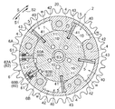
図3に示すように、上記外部ロータ2には、径内方向に突出するシューとして機能する突部4の複数個が回転方向に沿って互いに離間して並設されている。
外部ロータ2の隣接する突部4の夫々の間には、外部ロータ2と内部ロータ1で規定される流体圧室40が形成されている。図示するものにあっては、4室備えられている。
【0032】
内部ロータ1の外周部の、上記各流体圧室40に対面する個所にはベーン溝41が形成されており、このベーン溝41には、上記流体圧室40を相対回転方向(図3において矢印S1,S2方向)において進角室43と遅角室42とに仕切るベーン5が放射方向に沿って摺動可能に挿入されている。
【0033】
このベーン5は、図2に示すように、その内径側に備えられるスプリング51により、流体圧室内壁面w側に付勢されている。
【0034】
また、上記進角室43は内部ロータ1に形成された進角通路11に連通し、遅角室42は内部ロータ1に形成された遅角通路10に連通し、進角通路11及び遅角通路10は、後述する油圧回路7に接続されている。
一方、図2に示すように、内部ロータ1とフロントプレート22との間に、ベーン5を進角方向に常時付勢するためのトーションコイルスプリング27が備えられている。
【0035】
〔回転位相拘束機構〕
内部ロータ1と外部ロータ2との間には、相対回転位相が最進角位相と最遅角位相との間に設定された所定のロック位相(図3、4に示す位相)にあるときに、内部ロータ1と外部ロータ2との相対回転を拘束可能なロック機構6が設けられている。
【0036】
このロック機構6は、外部ロータ2に設けられた遅角用ロック部6A及び進角用ロック部6Bと、内部ロータ1の外周部の一部に凹状の一対のロック油溝62(これまで説明してきたロック溝である)とを備えて構成されている。
【0037】
遅角用ロック部6A及び進角用ロック部6Bは、外部ロータ2に径方向において摺動自在に設けられたロック体60と、ロック体60を径内方向に付勢するスプリング61とを備えて構成されている。尚、ロック体60の形状は、その用途に従って、プレート形状、ピン形状、又はその他の形状を採用することができる。ロック体60の具体的構成の一例を図8に示した。
【0038】
図3に示すように、上記遅角用ロック部6Aは、ロック体60をロック油溝62内に突入させることで、内部ロータ1が外部ロータ2に対して遅角方向へ相対回転することを阻止し、上記進角用ロック部6Bは、ロック体60をロック油溝62内に突入させることで、内部ロータ1が外部ロータ2に対して進角方向へ相対回転することを阻止する。
【0039】
遅角用ロック部6A及び進角用ロック部6Bの両方のロック体60が、ロック油溝62内に突入した状態で、内部ロータ1と外部ロータ2との相対回転位相を、最進角位相と最遅角位相との中間に設定された所定のロック位相に拘束する所謂ロック状態となる。
尚、上記ロック位相は、エンジン100の弁の開閉時期がエンジンの円滑な始動性が得られるような位相に設定されている。
【0040】
ここで、ロック体60のロック油溝62内への突入は、ロック油溝62内に油圧回路7を介して供給されるロック油がドレインされた状態で、スプリング61による付勢で発生する。一方、ロック体60のロック油溝62からの離脱は、ロック油溝62に油圧回路7を介してロック油が供給された状態で発生する。
従って、ロック油の給排出がロック機構6の動作を支配する。
但し、ロックされるためには、上述の外部ロータ2と内部ロータ1との相対回転位相がロック位相となっている必要があることは当然である。
【0041】
さて、図7に示すように、相対回転位相が最遅角位相とロック位相との間にある状態において、一対のロック体60について、その進角規制用に設けられているロック体60Bは、回転方向においてロック油溝62間の内部ロータ1表面に当接する。
この表面位置は、他の内部ロータ1部位の表面位置より僅かに径方向で内側に設定されている。従って、この表面部位は、進角用ロック体60Bの案内路L1として働き、このロック体60Bが進角用ロック油溝62B上に到達した段階で、進角用ロック体60Bの遅角側端面が、溝壁面に当接し、ロック体60Bの侵入を確実なものとするように構成されている。
【0042】
〔作動油の給排出構成〕
油圧回路7は、基本的に、上記進角通路11及び上記遅角通路10を介して進角室43及び遅角室42の一方若しくは両方に対する作動油としてのオイルの給排出を実行し、ベーン5の流体圧室40での相対位置を変更し、外部ロータ2と内部ロータ1との相対回転位相を最進角位相(進角室43の容積が最大となるときの相対回転位相)と最遅角位相(遅角室42の容積が最大となるときの相対回転位相)との間で調整可能な回転位相調整機構の一部として機能する。
さらに、この相対回転位相設定を実行するのに必要となる、ロック機構6によるロック、ロック解除動作をも実行する。
【0043】
さらに詳細に、以下、個々に説明する。
図3に示すように、油圧回路7は、エンジンの駆動力で駆動し、作動油又は後述のロック油となるオイルを供給するオイルポンプ70と、電子制御ユニットECUによる給電量制御によりスプールの位置を変化させて複数のポートにおけるオイルの給排出を実行するソレノイド式のオイルコントロールバルブOCVと、オイルを貯留するオイルパン75とを備えている。
【0044】
上記進角通路11及び上記遅角通路10が、上記オイルコントロールバルブOCVの所定のポートに互いに独立に接続されている。
【0045】
上記ロック油溝62は内部ロータ1に形成されたロック油通路63に連通し、ロック油通路63は上記油圧回路7のオイルコントロールバルブOCVにおける所定のポートに、前記遅角通路10、前記進角通路11に対して独立に接続されている。
【0046】
即ち、油圧回路7は、ロック油通路63を介して、ロック油溝62にロック油としてオイルの給排出を実行するように構成され、オイルコントロールバルブOCVからロック油溝62にロック油が供給されると、図4に示すように、ロック体60が外部ロータ2側に退避して、外部ロータ2と内部ロータ1との相対回転のロック状態が解除される。この姿勢をロック解除姿勢と呼び、ロックされている姿勢をロック姿勢と呼ぶ。さらに、相対回転位相がロック位相になく、ロック油の供給が断たれている状態を、本願にあっては、ロック待機姿勢と呼ぶ。
また、本願にあっては、エンジンの逆転により、ロック体がロック位相に移動される位相を、ロック待機位相と呼ぶ。本実施形態にあっては、最遅角位相からロック位相までの位相である。
【0047】
〔オイルコントロールバルブの動作制御〕
図5に示すように、油圧回路7のオイルコントロールバルブOCVは、電子制御ユニットECUからの給電量に比例してスプール位置を位置W1から位置W4まで変化させ、進角室43、遅角室42、ロック油溝62に、作動油、ロック油となるオイルの供給、ドレイン、停止等を切り替えるように構成されている。
【0048】
即ち、オイルコントロールバルブOCVのスプール位置を位置W1とすることで、進角室43及び遅角室42の作動油と共にロック油溝62のロック油をオイルパン75側にドレインするドレイン操作を実行することができる。
【0049】
オイルコントロールバルブOCVのスプール位置を位置W2とすることで、ロック油溝62にロック油が供給されて外部ロータ2と内部ロータ1との相対回転のロック状態を解除し、更に、遅角室42の作動油をドレインしつつ、進角室43に作動油を供給して、外部ロータ2と内部ロータ1との相対回転位相を進角方向S2に移動する進角移行操作を実行することができる。
【0050】
オイルコントロールバルブOCVのスプール位置を位置W3とすることで、外部ロータ2と内部ロータ1との相対回転のロックを解除しつつ、進角室43及び遅角室42に対する作動油の供給を停止して、外部ロータ2と内部ロータ1との相対回転位相をその時点での位相に保持する保持操作を実行することができる。
【0051】
オイルコントロールバルブOCVのスプール位置を位置W4とすることで、外部ロータ2と内部ロータ1との相対回転のロックを解除しつつ、更に、進角室43の作動油をドレインしつつ、遅角室42に作動油を供給して、外部ロータ2と内部ロータ1との相対回転位相を遅角方向S1に移動する遅角移行操作を実行することができる。
尚、オイルコントロールバルブOCVの作動構成は、上記のものに限定されるものではなく、適宜変更可能である。
【0052】
〔電子制御ユニット〕
電子制御ユニットECUには、所定のプログラム等を格納したメモリ、CPU、入力出力インターフェース等が内蔵されている。このユニットECUには、先に示した様々な検出信号が入力されてくる。
【0053】
電子制御ユニットECUは、カム角センサ111で検知したカムシャフト3の位相と、クランク角センサ112で検知したクランクシャフト8の位相とから、カムシャフトとクランクシャフトの相対回転位相、即ち、弁開閉時期制御装置本体VVTにおける内部ロータ1と外部ロータ2との相対回転位相を求めることができる構成とされている。この相対回転位相の導出は、相対回転位相導出手段C4が実行する。
従って、本願で問題となるIG−OFF指令の入力時に、前記相対回転位相はこのユニットECU内で判明していることとなる。
【0054】
電子制御ユニットECUには、IG−OFF指令に伴って独特の動作を実行する手段が備えられている。
図1,2に示すように、エンジン停止指令であるIG−OFF指令に従って、所定タイミングで、ロック油溝62から油圧をドレンする制御を実行するロック制御手段C1が備えられている。この手段C1が働くことにより、ロック油溝62に供給されていた油圧が解除され、ロック体60が、そのロック解除姿勢からロック姿勢への移行動作可能なロック待機状態とされる。従って、相対回転位相がロック位相に到達すれば、自動的にロックがかかることとなる。
【0055】
さらに、電子制御ユニットECUには、エンジン100を逆回転制御するための所定の操作を実行するエンジン制御手段C2が備えられている。
このエンジン制御手段C2による具体的な制御は、エンジン吸入空気量の増大制御、あるいは、元来、発電用にクランクシャフト8と一体に備えられる電動機9を利用したエンジン100の逆転制御である。
【0056】
さらに、電子制御ユニットECUには、IG−OFF指令以降、エンジンの逆回転以前に、オイルコントロールバルブOCVを制御して相対回転位相を最遅角位相とロック位相との間のロック待機位相とする位相制御手段C3が備えらている。
この位相制御手段C3による制御は、IG−OFF指令の入力時に、ユニットECU内で認識されている相対回転位相が、ロック位相と最進角位相との間にあると判別された場合に、これが働くように構成されている。
【0057】
〔動作〕
以下、本願における電子制御ユニットECUの所定機能を含む弁開閉時期制御装置のIG−OFF指令入力以降の動作について、第一の実施形態、第二の実施形態について説明する。
【0058】
1.第一実施の形態
この実施の形態は、イグニッションスイッチ109から入力されるIG−OFF指令に伴って、エンジン吸入空気量を増加させて、エンジンの逆回転をエンジン停止最終段階で起こさせロックをかける所謂、停止ロックを実現するための構成である。
【0059】
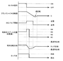
この動作形態におけるイグニッションスイッチ信号(IG/SW信号)、クランクシャフト回転数、ISCバルブ開度、制御弁スプール位置、相対回転位相、ロック油の供給・排除状態を図6に示した。
【0060】
動作は以下の順を追うこととなる。
1.エンジン100の停止信号(IG−OFF)の後、相対回転位相を中間ロック位置より遅角側へ移動させるためのオイルコントロールバルブOCVの制御をおこなう(この制御時には、相対回転位相を検知するものとはせず、ある一定時間で制御する)。但し、現状で認識されている相対回転位相が、ロック位相と最進角位相との間にある場合に限る。
この制御は、先に示した位相制御手段C3によるものであり、所定時間の制御を施すことで、自動的に相対回転位相を、最遅角位相からロック位相までのロック待機位相に、確実に設定することができる。
2. 引き続き、ロック油溝62の油圧を解除する制御を施す。この制御は、上記したロック制御手段C1による制御である。この制御を施すことで、相対回転位相がロック位相に到達した場合に、ロックがかかることとなる。
さらに、エンジン100が完全に停止する前に、ISCバルブ104bを開く指令を出す。この制御はエンジン制御手段C2によるものとなる。
エンジン100がほぼ停止する瞬間において、ISCバルブ104bが開いた状態では、エンジン100内において、インテークの負圧発生が抑えられ、ピストンを正回転方向へ回す力が弱くなり、圧縮流のシリンダの圧縮力によってピストンが逆回転方向に押され、クランクシャフト8を逆回転させることとなる。
【0061】
結果、クランクシャフト8の逆回転に伴って、これと同期回転している外部ロータ2が逆回転し、相対回転位相は進角方向へずれる。相対回転位相がロック位相に到達することによって、所謂、停止ロックがかかる。
【0062】
2.第二実施の形態
上記の実施の形態にあっては、エンジン制御手段C2による制御を施すに、エンジン吸入空気量の増大制御で、逆転を発生させるものとしたが、エンジンのクランクシャフト8に電動機9を備えたものにあっては、この電動機9を逆転用に使用することができる。
この制御が可能なエンジン制御システムの構成を図9に示した。この電動機9の運転制御は、先に示した例と同様に、電子制御ユニットECUに備えられるエンジン制御手段C2によるものとされる。
この実施形態をとる場合の動作は、先に説明した実施の形態の記載方式と同様に示すと以下のようになる。
【0063】
〔動作〕
この動作形態におけるイグニッションスイッチ信号(IG/SW信号)、クランクシャフト回転数、電動機回転、制御弁スプール位置、相対回転位相、ロック油の供給・排除状態を図10に示した。
1.エンジン100の停止信号(IG−OFF信号)の後、相対回転位相を中間ロック位置より遅角側へ移動させるためのオイルコントロールバルブOCVの制御をおこなう(この制御時には、先の実施の形態と同様に、相対回転位相を検知するものとはせず、ある一定時間での制御とする)。但し、現状で認識されている相対回転位相が、ロック位相と最進角位相との間にある場合に限る。
この制御は、先に示した位相制御手段C3によるものであり、所定時間の制御を施すことで、自動的に相対回転位相を、最遅角位相からロック位相までのロック待機位相に、確実に設定することができる。
2.引き続き、ロック油溝62の油圧を解除する制御を施す。この制御は、上記したロック制御手段C1による制御である。この制御を施すことで、相対回転位相がロック位相に到達した場合に、ロックがかかることとなる。
さらに、エンジンが完全に停止した後、エンジン制御手段C2による逆回転制御をかけ、電動機9によるクランクシャフト8の逆回転を行う。この逆回転量は、最大、相対位相回転に関し、最遅角位相からロック位相にロックされるまでの位相を回転する量とする。
こうすることで、相対回転位相は、ロック位相側に戻され、良好にロックをかけることができる。
【0064】
〔別実施の形態〕
本願の別実施の形態に関して説明する。
(1) 上記の実施の形態にあっては、エンジン停止後、一旦、遅角方向へのオイルコントロールバルブOCVを使用する油圧制御を施し、その後、ロック油をドレンするものとしたが、バルブ構成に関して、遅角方向への移動とロック油のドレン操作を同時的に実行できるものにあっては、これら操作を同時的に実行できるものとしてもよい。
(2) 上記の実施の形態にあっては、ロック体がロータの径方向に移動することで、ロック、ロック解除操作を施すものとしたが、この方向はロータの軸方向に沿ったもの、この軸あるいは径方向に対して傾斜したものとしてもよい。
(3) 上記の実施の形態にあっては、一対のロック体を備えてロック機構を構成したが、ロック体が単一で、ロック油溝が、先に示したものより幅狭のものとしてもよい。
【図面の簡単な説明】
【図1】本願の弁開閉時期制御装置を備えたエンジン周りのシステム構成を示す図
【図2】本願の弁開閉時期制御装置の概略構成を示す側断面図
【図3】ロック機構による相対回転位相のロック状態を示す立断面図
【図4】ロック機構によるロック位相でのロック解除状態を示す立断面図
【図5】オイルコントロールバルブの作動構成を示す図
【図6】第一実施の形態における、エンジン停止指令以降における弁開閉時期制御装置の状態を示すタイミングチャート
【図7】ロック待機位相における弁開閉時期制御装置の状態を示す立断面図
【図8】ロック体の斜視図
【図9】第二実施の形態におけるエンジン周りのシステム構成を示す図
【図10】第二実施の形態における、エンジン停止指令以降における弁開閉時期制御装置の状態を示すタイミングチャート
【符号の説明】
1 :内部ロータ
2 :外部ロータ
3 :カムシャフト
4 :突部
5 :ベーン
6 :ロック機構
6A :遅角用ロック部
6B :進角用ロック部
7 :油圧回路
8 :クランクシャフト
9 :電動機
100 :エンジン
104b:ICSバルブ
ECU :電子制御ユニット
OCV :オイルコントロールバルブ
VVT :弁開閉時期制御装置[0001]
BACKGROUND OF THE INVENTION
The present invention comprises a driving side rotating member that rotates synchronously with respect to the crankshaft, and a driven side rotating member that is disposed coaxially with the driving side rotating member and rotates together with the camshaft.
A rotation phase adjustment mechanism that adjusts a relative rotation phase between the drive side rotation member and the driven side rotation member by hydraulic control, and a rotation phase restriction mechanism that restricts the relative rotation phase at a lock phase;
The lock phase is set to an intermediate phase region between the most retarded angle phase and the most advanced angle phase,
The present invention relates to a valve opening / closing timing control device in which the rotational phase restricting mechanism can change its posture between a lock releasing posture in which relative rotation of the two rotating members is permitted by hydraulic control and a lock posture in which the rotational phase is restricted.
[0002]
[Prior art]
In this type of valve opening / closing timing control device, the relative rotational phase between the driving side rotating member and the driven side rotating member can be changed and set by controlling the rotational position of the vane provided in the fluid pressure chamber. A suitable operation state is achieved by appropriately setting the relative rotation phase corresponding to the operation state.
[0003]
The basic structure of this kind of opening / closing timing control device will be briefly described. As shown in FIGS. 2 and 3, the
[0004]
In this type of valve opening / closing timing control device, when the engine is stopped, the relative rotation phase of both rotors is guided to the lock phase, and control is performed so that the next engine start is started in the locked state.
In this type of control, the hydraulic pressure remains after the ignition switch is turned off (hereinafter referred to as IG-OFF) by the hydraulic control in the advance chamber and retard chamber provided in the valve timing control device. There are one that controls the relative rotational phase to the lock phase in a short time (the former technique below) and one that uses the engine reverse rotation when the engine is stopped (the latter technique below).
[0005]
The former technique is intended for intermediate locking, and detects the relative rotational phase by some means, and executes hydraulic control for the advance and retard chambers to bring the rotational phase closer to the lock phase. The lock phase is reached by hydraulic control.
(Patent Document 1).
[0006]
As the technology belonging to the latter, it is a relatively old technology that does not employ an intermediate lock structure, uses an electric motor connected to the crankshaft to cause reverse rotation of the engine (Patent Document 2), and is relatively new. Thus, there is an apparatus that increases the amount of intake air to the engine while adopting an intermediate lock structure and causes engine reverse rotation at the final stage when the engine is stopped (Patent Document 3).
[0007]
In the latter technique, the lock mechanism, which is a rotational phase restraint mechanism, needs to be set in a state where the lock can be applied after the engine is stopped (the lock mechanism is provided with a lock body, and in the lock posture, the lock body is In the case of a structure in which the lock enters the lock groove and is locked, it is necessary to establish a state in which the hydraulic pressure is released from the lock groove). The oil pressure supply system was common to the oil pressure system for causing the relative movement of the vanes.
[0008]
[Patent Document 1]
JP 2001-50063 A
[Patent Document 2]
JP 2002-266669 A
[Patent Document 3]
JP 2000-320356 A
[0009]
[Problems to be solved by the invention]
In the technology that applies the hydraulic control to the vane and locks the stop, even after IG-OFF, the relative rotation phase is detected, and a method to reliably control the lock phase at the stop is applied. It is necessary to execute a proper hydraulic pressure control so as to reliably reach the lock phase when stopped.
However, when using the oil pressure generated depending on this kind of engine rotation, from the relative rotation phase at the time of IG-OFF to the vicinity of the lock phase, using the oil pressure remaining in a short time after IG-OFF, Alternatively, since it is necessary to perform control up to the lock phase, it is not reliable in terms of obtaining a reliable lock guarantee.
[0010]
On the other hand, in the latter technique, conventionally, the hydraulic pressure is supplied to the lock groove from the hydraulic pressure supply system for the advance chamber or the retard chamber provided for adjusting the rotational phase. For this reason, when oil discharge from the lock groove is delayed, the lock mechanism itself cannot shift to the lock posture, which is problematic in this respect.
[0011]
An object of the present invention is to obtain an opening / closing timing control device that can reliably and reliably lock a so-called stop lock when the relative rotation phase is shifted to the lock phase after IG-OFF. There is.
[0012]
[Means for Solving the Problems]
In order to achieve the above object, according to the present application,
A driving-side rotating member that rotates synchronously with respect to the crankshaft; and a driven-side rotating member that is arranged coaxially with the driving-side rotating member and rotates together with the camshaft;
A rotation phase adjustment mechanism that adjusts a relative rotation phase between the drive side rotation member and the driven side rotation member by hydraulic control, and a rotation phase restriction mechanism that restricts the relative rotation phase at a lock phase;
The lock phase is set to an intermediate phase region between the most retarded angle phase and the most advanced angle phase,
A valve opening / closing timing control device in which the rotation phase restricting mechanism is changeable between a lock releasing posture in which relative rotation of the two rotating members is allowed by hydraulic control and a locking posture in which the rotation is restricted. As described in
In accordance with an engine stop command, the rotation phase restraint mechanism is provided with a lock control means for setting a lock standby state in which the transition operation from the unlocked posture to the locked posture can be performed, and an engine control means for performing reverse rotation control of the engine,
In the lock standby state realized by the lock control means, the lock posture of the rotational phase restraining mechanism is ensured by the reverse engine rotation realized by the engine control means.
[0013]
The valve opening / closing timing control device of this configuration is provided with a lock control means and an engine control means, and after the IG-OFF, the lock means can move the rotational phase restricting mechanism from the unlocked posture to the locked posture. Lock waiting state.
Therefore, the operation of this control means enables the rotational phase restraint mechanism to easily and reliably execute the posture change from the unlocked posture to the locked posture when the rotational phase reaches the lock phase.
In this state, in the valve opening / closing timing control device of the present application, the hydraulic system for the rotational phase adjustment mechanism and the hydraulic system for the rotational phase restraining mechanism are configured to receive hydraulic pressure independently. It is not affected by the adjustment mechanism. Therefore, the reliability with respect to the lock is increased.
[0014]
On the other hand, the engine control means can control the engine reverse rotation so that the rotation phase can be shifted to the lock phase side due to the reverse rotation. realizable.
[0015]
In the above configuration, as described in
[0016]
As described above, when the engine is rotating normally, the engine stop operation basically works in a direction to advance the relative rotation phase to the retard side, and at the stage where engine reverse rotation occurs, the rotation phase reaches the maximum. Although there is a high possibility that the phase has reached between the retard angle phase and the lock phase, as in this configuration, the phase control means is provided, and at the IG-OFF stage, the retard angle side (the most retarded angle phase and The rotation phase is shifted between the lock phase and the engine is reversely rotated to move toward the lock phase (advance angle movement), whereby a reliable lock can be applied.
Since the lock phase is specified, this control can be controlled to move to the retard side for a predetermined time or a predetermined time less than that.
Here, when the engine is reversely rotated, the hydraulic pressure is also lowered, and the state where the unlocking cannot be maintained has been reached, so that the locking is surely performed.
[0017]
As control by the engine control means, increase control of the engine intake air amount as described in
This type of control can be easily realized by appropriately setting the control program in relation to the IG-OFF input in the conventional device configuration.
As a result, the stop lock can be reliably realized while following the conventional structure.
[0018]
In the configuration described so far, as described in
As the engine rotates backward, the lock body is moved close to the lock groove and enters the lock groove, so that the surface position of the other rotating member in the close movement path exceeds the lock groove. It is preferable that a guide path for the lock body is provided which is set on the inner side of the groove from the surface position of the other rotating member in the extension path of the proximity movement path on the other side.
[0019]
By adopting this configuration, when the lock body moves from the retard side to the lock groove while abutting against the surface of the other rotating member, the tip of the lock body hits the side wall of the lock groove, and the lock body is moved into the groove. A certain lock can be realized by directing the movement to.
[0020]
DETAILED DESCRIPTION OF THE INVENTION
An embodiment of the present invention will be described with reference to FIGS.
3, 4 and 7 are functional explanatory drawings partially using the outline of the AA cross section in FIG.
[0021]
[Schematic configuration of the engine control system of the present application]
This system includes an intake system that supplies fuel and combustion air to the
[0022]
Referring to the mechanical configuration around the engine, as shown in FIG. 1, an
[0023]
A
Therefore, it is possible to reverse the
[0024]
Under the
A
[0025]
The valve opening / closing timing control device main body VVT receives an instruction from the electronic control unit ECU, the oil control valve OCV operates, and the operation of the valve opening / closing timing control device main body VVT is controlled.
The electronic control unit ECU has an ignition switch (IG / SW)
109, an operation command is input from the
Furthermore, a
The electronic control unit ECU outputs operation commands to the oil control valve OCV, the
[0026]
[Basic configuration of the valve timing control device body]
As shown in FIGS. 1 and 2, the valve opening / closing timing control device main body VVT is coaxial with the
[0027]
The
[0028]
The
[0029]
A
[0030]
When the
[0031]
[Rotation phase adjustment mechanism]
As shown in FIG. 3, the
A
[0032]
A
[0033]
As shown in FIG. 2, the
[0034]
The
On the other hand, as shown in FIG. 2, a
[0035]
[Rotation phase constraint mechanism]
Between the
[0036]
The
[0037]
The
[0038]
As shown in FIG. 3, the
[0039]
With the
The lock phase is set so that the valve opening / closing timing of the
[0040]
Here, the rush of the
Accordingly, the supply and discharge of the lock oil dominates the operation of the
However, in order to be locked, it is natural that the relative rotation phase between the
[0041]
Now, as shown in FIG. 7, in a state where the relative rotational phase is between the most retarded phase and the lock phase, the
This surface position is set slightly inward in the radial direction from the surface position of the other
[0042]
[Fluid supply / discharge configuration]
The
Furthermore, the locking and unlocking operations by the
[0043]
Further details will be described individually below.
As shown in FIG. 3, the
[0044]
The
[0045]
The
[0046]
That is, the
Further, in the present application, a phase in which the lock body is moved to the lock phase due to the reverse rotation of the engine is referred to as a lock standby phase. In this embodiment, the phase is from the most retarded phase to the lock phase.
[0047]
[Operation control of oil control valve]
As shown in FIG. 5, the oil control valve OCV of the
[0048]
That is, by setting the spool position of the oil control valve OCV to the position W1, a drain operation for draining the lock oil in the
[0049]
By setting the spool position of the oil control valve OCV to the position W2, the lock oil is supplied to the
[0050]
By setting the spool position of the oil control valve OCV to the position W3, the supply of hydraulic oil to the
[0051]
By setting the spool position of the oil control valve OCV to the position W4, the retardation chamber is released while unlocking the relative rotation between the
The operation configuration of the oil control valve OCV is not limited to the above, and can be changed as appropriate.
[0052]
[Electronic control unit]
The electronic control unit ECU incorporates a memory storing a predetermined program, a CPU, an input / output interface, and the like. Various detection signals described above are input to this unit ECU.
[0053]
The electronic control unit ECU determines the relative rotational phase of the camshaft and the crankshaft, that is, the valve opening / closing timing from the phase of the
Therefore, when the IG-OFF command, which is a problem in the present application, is input, the relative rotational phase is known in the unit ECU.
[0054]
The electronic control unit ECU is provided with means for executing a unique operation in accordance with the IG-OFF command.
As shown in FIGS. 1 and 2, lock control means C <b> 1 is provided that executes control for draining hydraulic pressure from the
[0055]
Further, the electronic control unit ECU is provided with engine control means C2 that executes a predetermined operation for controlling the
The specific control by the engine control means C2 is an increase control of the engine intake air amount or a reverse rotation control of the
[0056]
Further, the electronic control unit ECU controls the oil control valve OCV after the IG-OFF command and before the reverse rotation of the engine to set the relative rotation phase to the lock standby phase between the most retarded phase and the lock phase. Phase control means C3 is provided.
The control by the phase control means C3 is performed when it is determined that the relative rotation phase recognized in the unit ECU is between the lock phase and the most advanced angle phase when the IG-OFF command is input. Configured to work.
[0057]
[Operation]
Hereinafter, the first embodiment and the second embodiment will be described with respect to the operation after the IG-OFF command input of the valve timing control device including the predetermined function of the electronic control unit ECU in the present application.
[0058]
1. First embodiment
In this embodiment, in accordance with the IG-OFF command input from the
[0059]
FIG. 6 shows the ignition switch signal (IG / SW signal), crankshaft rotation speed, ISC valve opening, control valve spool position, relative rotation phase, and lock oil supply / exclusion state in this operation mode.
[0060]
The operation will follow the following order.
1. After the stop signal (IG-OFF) of the
This control is performed by the phase control means C3 described above. By performing the control for a predetermined time, the relative rotation phase is automatically set to the lock standby phase from the most retarded phase to the lock phase. Can be set.
2. Subsequently, control for releasing the hydraulic pressure of the
Further, before the
At the moment when the
[0061]
As a result, along with the reverse rotation of the
[0062]
2. Second embodiment
In the above embodiment, in order to perform the control by the engine control means C2, the reverse rotation is generated by the increase control of the engine intake air amount, but the
The configuration of an engine control system capable of this control is shown in FIG. The operation control of the electric motor 9 is performed by the engine control means C2 provided in the electronic control unit ECU, as in the example described above.
The operation in the case of adopting this embodiment is as follows when shown in the same manner as the description method of the embodiment described above.
[0063]
[Operation]
FIG. 10 shows the ignition switch signal (IG / SW signal), crankshaft rotation speed, motor rotation, control valve spool position, relative rotation phase, and lock oil supply / exclusion state in this operation mode.
1. After the stop signal (IG-OFF signal) of the
This control is performed by the phase control means C3 described above. By performing the control for a predetermined time, the relative rotation phase is automatically set to the lock standby phase from the most retarded phase to the lock phase. Can be set.
2. Subsequently, control for releasing the hydraulic pressure of the
Further, after the engine is completely stopped, reverse rotation control is performed by the engine control means C2, and the
By doing so, the relative rotational phase is returned to the lock phase side and can be locked well.
[0064]
[Another embodiment]
Another embodiment of the present application will be described.
(1) In the above embodiment, after the engine is stopped, the hydraulic control using the oil control valve OCV in the retarding direction is once performed, and then the lock oil is drained. With respect to the above, if the movement in the retarding direction and the drain operation of the lock oil can be performed simultaneously, these operations may be performed simultaneously.
(2) In the above embodiment, the lock body is moved in the radial direction of the rotor, so that the locking and unlocking operations are performed. This direction is along the axial direction of the rotor, It may be inclined with respect to this axis or radial direction.
(3) In the above embodiment, the lock mechanism is configured with a pair of lock bodies, but the lock body is single and the lock oil groove is narrower than the one shown above. Also good.
[Brief description of the drawings]
FIG. 1 is a diagram showing a system configuration around an engine provided with a valve timing control device of the present application.
FIG. 2 is a side sectional view showing a schematic configuration of the valve timing control device of the present application.
FIG. 3 is an elevational sectional view showing a locked state of a relative rotational phase by a lock mechanism.
FIG. 4 is an elevational sectional view showing an unlocked state at a lock phase by a lock mechanism.
FIG. 5 is a diagram showing an operation configuration of an oil control valve.
FIG. 6 is a timing chart showing the state of the valve opening / closing timing control device after the engine stop command in the first embodiment.
FIG. 7 is an elevational sectional view showing a state of the valve timing control device in the lock standby phase.
FIG. 8 is a perspective view of the lock body.
FIG. 9 is a diagram showing a system configuration around an engine in the second embodiment.
FIG. 10 is a timing chart showing the state of the valve opening / closing timing control device after the engine stop command in the second embodiment.
[Explanation of symbols]
1: Internal rotor
2: External rotor
3: Camshaft
4: Projection
5: Vane
6: Lock mechanism
6A: Delay angle lock section
6B: Advance lock section
7: Hydraulic circuit
8: Crankshaft
9: Electric motor
100: Engine
104b: ICS valve
ECU: Electronic control unit
OCV: Oil control valve
VVT: Valve opening / closing timing control device
Claims (5)
油圧制御により前記駆動側回転部材と前記従動側回転部材との相対回転位相が調整される回転位相調整機構と、前記相対回転位相をロック位相において拘束する回転位相拘束機構とを備え、
前記ロック位相が最遅角位相と最進角位相との中間位相域に設定され、
前記回転位相拘束機構が、油圧制御により前記両回転部材の相対回転を許容するロック解除姿勢と、拘束するロック姿勢との間で姿勢変更可能とされる弁開閉時期制御装置であって、
前記回転位相調整機構に対する油圧系統と、前記回転位相拘束機構に対する油圧系統とが、独立に油圧供給を受ける構成を有し、
エンジン停止指令に従って、前記回転位相拘束機構を、前記ロック解除姿勢から前記ロック姿勢への移行動作可能なロック待機状態とするロック制御手段と、エンジンを逆回転制御するエンジン制御手段とを備え、
前記ロック制御手段により実現される前記ロック待機状態において、前記エンジン制御手段により実現されるエンジン逆回転により、前記回転位相拘束機構の前記ロック姿勢が確保される弁開閉時期制御装置。A driving-side rotating member that rotates synchronously with respect to the crankshaft; and a driven-side rotating member that is arranged coaxially with the driving-side rotating member and rotates together with the camshaft;
A rotation phase adjustment mechanism that adjusts a relative rotation phase between the drive side rotation member and the driven side rotation member by hydraulic control, and a rotation phase restriction mechanism that restricts the relative rotation phase at a lock phase;
The lock phase is set to an intermediate phase region between the most retarded angle phase and the most advanced angle phase,
The rotational phase restraining mechanism is a valve opening / closing timing control device capable of changing a posture between a lock releasing posture that allows relative rotation of the two rotating members by hydraulic control and a lock posture that restricts the rotational phase;
The hydraulic system for the rotational phase adjustment mechanism and the hydraulic system for the rotational phase restraint mechanism have a configuration that receives hydraulic pressure independently,
In accordance with an engine stop command, the rotation phase restraint mechanism is provided with a lock control means for setting a lock standby state in which the transition operation from the unlocked posture to the locked posture can be performed, and an engine control means for performing reverse rotation control of the engine,
A valve opening / closing timing control device in which the lock posture of the rotation phase restricting mechanism is secured by reverse engine rotation realized by the engine control means in the lock standby state realized by the lock control means.
前記エンジンの逆回転に伴って、前記ロック体が前記ロック溝上まで近接移動されて前記ロック溝内に突入するに、前記近接移動経路にある前記他方の回転部材表面位置が、前記ロック溝を越えた側の前記近接移動経路の延長経路にある他方の回転部材表面位置より溝の内側に設定され、前記ロック体に対する案内路が設けられている請求項1〜4のいずれか1項記載の弁開閉時期制御装置。A locking body that the rotational phase restraining mechanism enters into the other rotating member from either one of the driving side rotating member and the driven side rotating member, and restrains the relative rotation of both rotating members; A lock groove provided on the other rotating member and engaged with the lock body,
As the engine rotates backward, the lock body is moved close to the lock groove and enters the lock groove, so that the surface position of the other rotating member in the close movement path exceeds the lock groove. The valve according to any one of claims 1 to 4, wherein the valve is set on the inner side of the groove from the surface position of the other rotating member in the extension path of the proximity movement path on the other side, and a guide path for the lock body is provided. Open / close timing control device.
Priority Applications (1)
| Application Number | Priority Date | Filing Date | Title |
|---|---|---|---|
| JP2003049244A JP4035770B2 (en) | 2003-02-26 | 2003-02-26 | Valve timing control device |
Applications Claiming Priority (1)
| Application Number | Priority Date | Filing Date | Title |
|---|---|---|---|
| JP2003049244A JP4035770B2 (en) | 2003-02-26 | 2003-02-26 | Valve timing control device |
Publications (2)
| Publication Number | Publication Date |
|---|---|
| JP2004257312A true JP2004257312A (en) | 2004-09-16 |
| JP4035770B2 JP4035770B2 (en) | 2008-01-23 |
Family
ID=33115008
Family Applications (1)
| Application Number | Title | Priority Date | Filing Date |
|---|---|---|---|
| JP2003049244A Expired - Fee Related JP4035770B2 (en) | 2003-02-26 | 2003-02-26 | Valve timing control device |
Country Status (1)
| Country | Link |
|---|---|
| JP (1) | JP4035770B2 (en) |
Cited By (5)
| Publication number | Priority date | Publication date | Assignee | Title |
|---|---|---|---|---|
| JP2009074383A (en) * | 2007-09-19 | 2009-04-09 | Aisin Seiki Co Ltd | Valve opening and closing timing control device |
| JP2010242531A (en) * | 2009-04-01 | 2010-10-28 | Toyota Motor Corp | Valve timing control device for internal combustion engine |
| WO2013031024A1 (en) * | 2011-09-02 | 2013-03-07 | トヨタ自動車株式会社 | Engine control device for vehicle |
| JP2013092107A (en) * | 2011-10-26 | 2013-05-16 | Hitachi Automotive Systems Ltd | Valve timing control device of internal combustion engine |
| KR101299749B1 (en) * | 2004-10-07 | 2013-08-23 | 섀플러 테크놀로지스 아게 운트 코. 카게 | Device for changing control time of gas-exchange valves of an internal combustion engine |
-
2003
- 2003-02-26 JP JP2003049244A patent/JP4035770B2/en not_active Expired - Fee Related
Cited By (5)
| Publication number | Priority date | Publication date | Assignee | Title |
|---|---|---|---|---|
| KR101299749B1 (en) * | 2004-10-07 | 2013-08-23 | 섀플러 테크놀로지스 아게 운트 코. 카게 | Device for changing control time of gas-exchange valves of an internal combustion engine |
| JP2009074383A (en) * | 2007-09-19 | 2009-04-09 | Aisin Seiki Co Ltd | Valve opening and closing timing control device |
| JP2010242531A (en) * | 2009-04-01 | 2010-10-28 | Toyota Motor Corp | Valve timing control device for internal combustion engine |
| WO2013031024A1 (en) * | 2011-09-02 | 2013-03-07 | トヨタ自動車株式会社 | Engine control device for vehicle |
| JP2013092107A (en) * | 2011-10-26 | 2013-05-16 | Hitachi Automotive Systems Ltd | Valve timing control device of internal combustion engine |
Also Published As
| Publication number | Publication date |
|---|---|
| JP4035770B2 (en) | 2008-01-23 |
Similar Documents
| Publication | Publication Date | Title |
|---|---|---|
| EP1781905B1 (en) | Variable valve timing control device | |
| JP5582363B2 (en) | Valve timing control device | |
| EP1672188B1 (en) | Valve timing control apparatus and method for setting minimum torque | |
| JP4000522B2 (en) | Valve timing control device | |
| US8677959B2 (en) | Variable valve timing controller for internal combustion engine | |
| JP5929300B2 (en) | Engine valve timing control device | |
| JP5321911B2 (en) | Valve timing control device | |
| JP2006144766A (en) | Valve opening/closing timing control device | |
| JP3791658B2 (en) | Variable valve timing control device for internal combustion engine | |
| US8919310B2 (en) | Valve open/close timing control device | |
| JP2010209780A (en) | Variable valve train for internal combustion engine | |
| JP4035770B2 (en) | Valve timing control device | |
| JP2011069245A (en) | Engine control device | |
| JP2001164908A (en) | Variable valve timing control device for internal combustion engine | |
| JP4531705B2 (en) | Valve timing control device | |
| US20020134334A1 (en) | Apparatus and method for controlling valve timing of engine | |
| JP6035880B2 (en) | Valve timing control device | |
| JP2009203830A (en) | Valve timing control device | |
| JP4123424B2 (en) | Valve timing control device | |
| JP6015136B2 (en) | Valve opening / closing timing control device and internal combustion engine control system | |
| JP2004340019A (en) | Valve timing control device for internal combustion engine mounted on vehicle | |
| JP2002266669A (en) | Variable valve timing control device for internal combustion engine | |
| JP2014199048A (en) | Valve opening/closing timing controller | |
| JP5584797B1 (en) | Valve timing control device for internal combustion engine |
Legal Events
| Date | Code | Title | Description |
|---|---|---|---|
| A621 | Written request for application examination |
Free format text: JAPANESE INTERMEDIATE CODE: A621 Effective date: 20051213 |
|
| A977 | Report on retrieval |
Free format text: JAPANESE INTERMEDIATE CODE: A971007 Effective date: 20070427 |
|
| A131 | Notification of reasons for refusal |
Free format text: JAPANESE INTERMEDIATE CODE: A131 Effective date: 20070510 |
|
| A521 | Written amendment |
Free format text: JAPANESE INTERMEDIATE CODE: A523 Effective date: 20070706 |
|
| TRDD | Decision of grant or rejection written | ||
| A01 | Written decision to grant a patent or to grant a registration (utility model) |
Free format text: JAPANESE INTERMEDIATE CODE: A01 Effective date: 20071004 |
|
| A61 | First payment of annual fees (during grant procedure) |
Free format text: JAPANESE INTERMEDIATE CODE: A61 Effective date: 20071017 |
|
| R151 | Written notification of patent or utility model registration |
Ref document number: 4035770 Country of ref document: JP Free format text: JAPANESE INTERMEDIATE CODE: R151 |
|
| FPAY | Renewal fee payment (event date is renewal date of database) |
Free format text: PAYMENT UNTIL: 20101109 Year of fee payment: 3 |
|
| FPAY | Renewal fee payment (event date is renewal date of database) |
Free format text: PAYMENT UNTIL: 20101109 Year of fee payment: 3 |
|
| FPAY | Renewal fee payment (event date is renewal date of database) |
Free format text: PAYMENT UNTIL: 20111109 Year of fee payment: 4 |
|
| FPAY | Renewal fee payment (event date is renewal date of database) |
Free format text: PAYMENT UNTIL: 20111109 Year of fee payment: 4 |
|
| FPAY | Renewal fee payment (event date is renewal date of database) |
Free format text: PAYMENT UNTIL: 20121109 Year of fee payment: 5 |
|
| FPAY | Renewal fee payment (event date is renewal date of database) |
Free format text: PAYMENT UNTIL: 20131109 Year of fee payment: 6 |
|
| LAPS | Cancellation because of no payment of annual fees |