JP2004250079A - Cap - Google Patents
Cap Download PDFInfo
- Publication number
- JP2004250079A JP2004250079A JP2003044703A JP2003044703A JP2004250079A JP 2004250079 A JP2004250079 A JP 2004250079A JP 2003044703 A JP2003044703 A JP 2003044703A JP 2003044703 A JP2003044703 A JP 2003044703A JP 2004250079 A JP2004250079 A JP 2004250079A
- Authority
- JP
- Japan
- Prior art keywords
- lid
- cap
- hinge block
- side hinge
- hole
- Prior art date
- Legal status (The legal status is an assumption and is not a legal conclusion. Google has not performed a legal analysis and makes no representation as to the accuracy of the status listed.)
- Granted
Links
- XLYOFNOQVPJJNP-UHFFFAOYSA-N water Substances O XLYOFNOQVPJJNP-UHFFFAOYSA-N 0.000 claims abstract description 48
- 238000000605 extraction Methods 0.000 claims description 35
- 230000008878 coupling Effects 0.000 abstract description 2
- 238000010168 coupling process Methods 0.000 abstract description 2
- 238000005859 coupling reaction Methods 0.000 abstract description 2
- 230000002093 peripheral effect Effects 0.000 description 11
- 238000004891 communication Methods 0.000 description 7
- 238000003780 insertion Methods 0.000 description 3
- 230000037431 insertion Effects 0.000 description 3
- 238000012986 modification Methods 0.000 description 3
- 230000004048 modification Effects 0.000 description 3
- 230000015572 biosynthetic process Effects 0.000 description 2
- 230000000694 effects Effects 0.000 description 2
- 238000007599 discharging Methods 0.000 description 1
- 239000000463 material Substances 0.000 description 1
- 235000013372 meat Nutrition 0.000 description 1
- 238000000465 moulding Methods 0.000 description 1
- 230000000149 penetrating effect Effects 0.000 description 1
- 239000011148 porous material Substances 0.000 description 1
- 229920005989 resin Polymers 0.000 description 1
- 239000011347 resin Substances 0.000 description 1
- 229920003002 synthetic resin Polymers 0.000 description 1
- 239000000057 synthetic resin Substances 0.000 description 1
Images


Landscapes
- Closures For Containers (AREA)
Abstract
Description
【0001】
【発明の属する技術分野】
本発明は、特段蓋体に隙間などを形成するばね片等を備える必要がなく、また外観が良好であるとともに、抽出物による目詰まりも防止でき、かつまた蓋体を閉じている状態ではキャップ本体内部が外部と直接連通されることのないキャップに関する。
【0002】
【従来の技術】
従来、各種の容器、特にチューブ容器の中には、これを逆さまに立てて置くことができるようにしたものが知られていて、このようにすることで容器を横に寝かせて置いておくよりも、場所をとらないという利点がある。このような容器に採用されるキャップはおおよそ、容器本体上部に、その抽出口周囲を取り囲んで被せられるキャップ本体と、容器本体の抽出口を開閉自在に閉じる蓋体と、蓋体をキャップ本体に回動自在に連結するヒンジとを備えて構成され、容器本体を逆さまにしてこのキャップを載置面上に設置することで、容器本体を倒立状態に支持することができるようになっている。
【0003】
ところが、このような容器を洗面所や浴室などの水場で使用し、使い終わった後、倒立させて置いておくと、容器本体に付着している水がその表面を伝って流下し、容器本体とこれに被せたキャップ本体との間から流れ込んで、当該キャップ本体内部に溜まってしまうという不具合があった。このような不具合を解消する目的で、容器本体との間からキャップ本体の内部に流入した水を蓋体側から外部へ流出させる構造を有するキャップが、例えば特許文献1〜3に開示されている。
【0004】
特許文献1では、3点ヒンジ形の弾性反転形キャップのキャップ本体が、小径の取付け用周壁と、大径の意匠周壁と、これら周壁間に位置し、抽出孔が形成された頂壁とを含み、頂壁部分に小孔を開け、この小孔から天蓋の弾性反転板両側の隙間を通して、キャップ本体内に回り込んだ水を外部に排出するようにしている。
【0005】
特許文献2では、キャップ本体を頂板、内筒および外筒から構成し、キャップ本体に、左右一対の連結片と略L字状ばね片とからなる反転ヒンジを介して開閉自在に蓋体を連結し、外筒の上部周壁部であって反転ヒンジの両連結片の間の部分に切欠穴を設けるとともに、閉蓋時にばね片の左右両側縁と蓋体との間に切欠穴と連通する空隙を設けるようにしている。
【0006】
特許文献3では、キャップ本体と上蓋とを備え、キャップ本体を天板、内筒および外筒から構成し、外筒の天板寄りに水抜き孔を設けるとともに、上蓋の外面に水抜き孔に続く水抜き誘導路を設け、この水抜き誘導路を上蓋の容器倒立時の接地面に向けて延在させるようにしている。
【0007】
【特許文献1】
実開平5−72747号公報
【特許文献2】
実開平6−18263号公報
【特許文献3】
特開2001−48203号公報
【0008】
【発明が解決しようとする課題】
ところで、上記特許文献1にあっては、頂壁部分に小孔を開けるようにしていたため、天蓋を開いたときに、頂壁部分に抽出孔と隣接して小孔が見えてしまい、外観上好ましくないとともに、抽出孔から抽出物を拭い取る際などに、抽出物で小孔に目詰まりを生じさせるおそれがあるという課題があった。また特許文献2にあっては、外筒に外部と直接連通する形態で、切欠穴を形成するようにしていたため、蓋体を開いているときはともかく、蓋体を閉じている不使用時でさえ、この切欠穴を介して水が直接外筒内に流入してしまうおそれがあるという課題があった。
【0009】
さらに、これら特許文献1および2にあっては排水のために、弾性反転板両側の隙間や、ばね片の左右両側縁と蓋体との間の、切欠穴と連通する空隙を利用するようにしていて、そのためにこれらばね片等の形成が必須であって、これらを備えないキャップには適用できない構造であった。
【0010】
他方、特許文献3は、上記弾性反転板等を備えることなく、キャップ本体内部から外部へ水を排出させることができるものであるが、外筒にその内部へ直接連通する水抜き孔を形成するようにしていたため、特許文献2と同様にこの水抜き孔が、かえって外筒内へ直接水を流入させる流入経路となってしまうという課題があった。また、上蓋の外面に水抜き誘導路を形成するようにしていたため、外観上好ましくないという課題もあった。
【0011】
本発明は上記従来の課題に鑑みて創案されたものであって、特段蓋体に隙間などを形成するばね片等を備える必要がなく、また外観が良好であるとともに、抽出物による目詰まりも防止でき、かつまた蓋体を閉じている状態ではキャップ本体内部が外部と直接連通されることのないキャップを提供することを目的とする。
【0012】
【課題を解決するための手段】
本発明にかかるキャップは、容器本体上部に、その抽出口周囲を取り囲んで被せられるキャップ本体と、該容器本体の抽出口を開閉自在に閉じる蓋体と、該蓋体を該キャップ本体に回動自在に連結するヒンジとを有し、該容器本体を倒立状態に支持しつつ、該容器本体との間から該キャップ本体の内部に流入した水を外部へ流出させるようにしたキャップにおいて、上記ヒンジを、上記キャップ本体から外方へ突出させて形成された本体側ヒンジブロックと、上記蓋体から外方へ突出させて形成されかつ該本体側ヒンジブロックに折り曲げ自在に連結され、該蓋体で上記抽出口を閉じている状態で該本体側ヒンジブロックに当接される蓋側ヒンジブロックとから構成するとともに、上記本体側ヒンジブロックと上記蓋側ヒンジブロックとの間に、上記キャップ本体内部に一端が連通され他端が外部と連通された流水孔を形成したことを特徴とする。
【0013】
本発明にあっては、キャップ本体内部と外部とを、キャップ本体および蓋体それぞれから外方へ突出形成した本体側ヒンジブロックと蓋側ヒンジブロックとの間に形成した流水孔で連通させるようにしていて、このように流水孔をヒンジブロックに形成していることから、蓋体に隙間などを形成するばね片等を備える必要性はなく、また蓋体を閉じているときはもちろんのこと、開いたときでもあまり目立つことがなくて良好な外観を得ることが可能であるとともに、抽出口から抽出物を拭い取る操作で抽出物が流水孔まで達する可能性を少なくすることができて、流水孔が抽出物で目詰まりすることを防止し得る。
【0014】
さらに、蓋体で抽出口を閉じている状態では、本体側ヒンジブロックに蓋側ヒンジブロックが当接されて、キャップ本体内部は流水孔を介してのみ、外部と連通される構造であり、蓋体を閉じている状態でキャップ本体内部が外部と直接連通されてこれに水が流入することを阻止し得る。
【0015】
また、前記流水孔の一端が、前記本体側ヒンジブロックを貫通して前記キャップ本体内部に向かって開口される貫通孔部であることを特徴とする。この貫通孔部により、キャップ本体内部は、容器本体を倒立させたときに、蓋側ヒンジブロックの上方に位置する本体側ヒンジブロックまで完全に外部と遮断されるため、外部から水が浸入することをさらに確実に阻止することが可能となる。
【0016】
さらに、前記流水孔の他端は、前記本体側ヒンジブロックおよび前記蓋側ヒンジブロックの一方に形成された溝部が、他方によって塞がれて形成されることを特徴とする。流水孔の他端が、互いに折り曲げ自在に連結された本体側ヒンジブロックと蓋側ヒンジブロックとの間で、それらの一方に形成した溝部で構成されることから、蓋体を開いたときに露出されるこの溝部を清掃することが可能で、流水孔の目詰まりをさらに確実に防止し得る。
【0017】
【発明の実施の形態】
以下に、本発明にかかるキャップの好適な一実施形態を、添付図面を参照して詳細に説明する。本実施形態にかかるキャップ1は図1〜図3に示すように、主に、チューブ容器などの容器本体2の上部に、当該容器本体2の抽出口3周囲を取り囲んで被せられるキャップ本体4と、容器本体2の抽出口3を開閉自在に閉じる蓋体5と、蓋体5をキャップ本体4に回動自在に連結するヒンジ6とが合成樹脂材により一体成形されて形成される。
【0018】
容器本体2は、抽出物を収容する筒体状の胴部7と、この胴部7上に、当該胴部7の外径よりも次第に縮径させて錐体状に形成された肩部8と、肩部8上に形成され、内部に抽出物を取り出すための抽出口3が形成された首部9とから構成される。
【0019】
キャップ本体4は、首部9上に配置される頂板10と、頂板10の下面から首部9周囲を取り囲むように垂下され、当該首部9にこれとの間に形成された係止部11を介して係止される内筒部12と、内筒部12の外側となる頂板10の外周縁から肩部8に向かって垂下され、キャップ1の外装体となる外筒部13とから構成される。頂板10の中央部には、下面から突出させて抽出口3内周に圧接される差込部14と、その上面から突出させて隆起部15が形成され、頂板10を貫通して隆起部15から差込部14にわたって抽出孔部16が形成される。
【0020】
そしてこのキャップ本体4は、抽出孔部16を抽出口3に連通させるべく、差込部14を抽出口3に差し込みつつ内筒部12を首部9に係止させることにより、その頂板10や外筒部13等で抽出口3周囲を取り囲んで、容器本体2の上部に被せて装着されるようになっている。
【0021】
蓋体5は、外形輪郭が頂板10の外形輪郭に一致させて形成された天板17と、天板17の外周縁から垂下させて形成された環状周壁18とから、全体として皿状に形成される。天板17の中央部には、抽出孔部16に挿抜自在に挿入され、これにより抽出口3を開閉自在に閉じる栓体19が突出形成される。
【0022】
栓体19は、弾性変形可能に中空軸体状に形成されるとともに、その周囲に環状突起20が形成され、抽出孔部16に挿入される際、抽出孔部16上部のテーパ面21に対し柔軟に変形しつつその内部へ進入して、環状突起20が抽出孔部16内の段付き部22に係脱自在に係合されるようになっていて、これにより抽出孔部16、ひいては抽出口3が栓体19によって液密に閉じられるとともに、キャップ本体4の頂板10上に、蓋体5の環状周壁18が重ね合わされるようになっている。
【0023】
ヒンジ6は、本体側ヒンジブロック23と蓋側ヒンジブロック24とから構成される。特に、本体側ヒンジブロック23は、キャップ本体4の外筒部13にこれより外方へ突起状に突出させて形成されるとともに、蓋側ヒンジブロック24もまた、蓋体5の環状周壁18にこれより外方へ突起状に突出させて形成される。図示例にあってはこれらヒンジブロック23,24はともに、三角柱状に形成され、一対の頂面23a,24aが横向きに、そして3つの側面のうち、一つの側面はそれぞれ外筒部13および環状周壁18との接合面となり、また一つの側面が互いに上下方向に向かい合い、さらに一つの側面が外方に突出する傾斜面23b,24bとなっている。
【0024】
本体側ヒンジブロック23および蓋側ヒンジブロック24は、蓋体5をキャップ本体4上に重ね合わせて蓋体5で抽出口3を閉じている状態で、互いに液密に当接される。図示例にあっては、本体側ヒンジブロック23および蓋側ヒンジブロック24の上記側面の一つがそれぞれ、外筒部13の上端面および環状周壁18の下端面と面一に形成した当接面23c,24cとされ、これら当接面23c,24cによって、本体側ヒンジブロック23と蓋側ヒンジブロック24とが互いに液密に当接される。また本体側ヒンジブロック23と蓋側ヒンジブロック24は、これら当接面23c,24cの外側先端で互いに折り曲げ自在に連結され、これにより蓋体5がキャップ本体4に回動自在に連結される。
【0025】
さらに、本体側ヒンジブロック23と蓋側ヒンジブロック24との間には、一端が外筒部内部に連通され、他端が外部と連通される流水孔25が形成される。本実施形態にあってはこの流水孔25は、本体側ヒンジブロック23を貫通して形成された貫通孔部26と、蓋側ヒンジブロック24を貫通して形成され、貫通孔部26と連通される連通孔部27とから構成される。
【0026】
貫通孔部26は、流水孔25の一端を形成し、上記傾斜面23bに沿って本体側ヒンジブロック23の当接面23cから外筒部13を貫通して、キャップ本体4内部に向かって開口される。また連通孔部27は、流水孔25の他端を形成し、蓋側ヒンジブロック24の当接面24cから当該蓋側ヒンジブロック24を上方に向かって貫通して、蓋側ヒンジブロック24の傾斜面24bに開口される。そして流水孔25は、ヒンジブロック23,24の当接面23c,24c同士が液密に当接されることにより、これら貫通孔部26および連通孔部27が一連に接続されて構成され、これによってキャップ本体4の外筒部13内部が外部に連通されるようになっている。
【0027】
そして容器本体2は、これを逆さまにしてキャップ1、具体的には蓋体5の天板17を載置面上に設置することにより、キャップ1で倒立状態に支持されて、立てて置かれるようになっている。なお、キャップ本体4および蓋体5には、ヒンジ6とは反対側位置に、蓋体5を開ける際の手がかりとなる窪み28とこの上に庇状に突出される指掛け部29とが形成される。
【0028】
本実施形態にかかるキャップ1の作用について説明する。不使用時にキャップ1を下にして容器本体2を倒立させて置いておくと図3に示すように、容器本体2に付着している水は流下し、容器本体2の肩部8とキャップ本体4の外筒部13との間の隙間からキャップ本体4内部に流れ込む。流れ込んだ水はキャップ本体4の外筒部13や内筒部12、さらには頂板10を伝って外筒部13に開口された、本体側ヒンジブロック23の貫通孔部26に達する。本体側ヒンジブロック23の貫通孔部26に達すると、水はこの貫通孔部26を経てさらに流下する。
【0029】
本体側ヒンジブロック23には、蓋側ヒンジブロック24が両者の当接面23c,24cを介して互いに液密に当接されているため、本体側ヒンジブロック23の貫通孔部26を流下する水は、さらに蓋側ヒンジブロック24の連通孔部27へ流れ込んで流下する。そして蓋側ヒンジブロック24の連通孔部27に流れ込んだ水は、そのまま外部へと流出されることになり、これによってキャップ本体4内部に水が溜まることを防止することができる。
【0030】
他方、容器本体2から抽出物を抽出する際には、通常通りヒンジ6を介してキャップ本体4に対し蓋体5を回動させ、栓体19を抽出孔部16から抜き出して開放すれば、抽出口3から抽出孔部16を介して抽出物を取り出すことができ、取り出し後は抽出孔部16周りの頂板10上面を拭うなどし、その後、蓋体5を回動させてキャップ本体4上に重ね合わせれば、抽出孔部16が栓体19で閉じられるとともに、ヒンジブロック23,24同士が互いに当接されて一連な流水孔25が形成される。
【0031】
以上説明した本実施形態にかかるキャップ1にあっては、キャップ本体4内部と外部とを、キャップ本体4および蓋体5それぞれから外方へ突出形成した本体側ヒンジブロック23と蓋側ヒンジブロック24との間に形成した流水孔25で連通させるようにしていて、このように流水孔25をヒンジブロック23,24に形成したので、蓋体5に隙間などを形成するばね片等を備える必要性はなく、さまざまな形態のキャップ1に適用することができ、また蓋体5を閉じているときはもちろんのこと、開いたときでもあまり目立つことがなくて、良好な外観を得ることができるとともに、頂板10上の抽出孔部16から抽出物を拭い取る際に、抽出物が流水孔25まで達する可能性を少なくすることができて、流水孔25が抽出物で目詰まりすることを防止することができる。
【0032】
さらに、蓋体5で抽出口3を閉じている状態では、本体側ヒンジブロック23に蓋側ヒンジブロック24を液密に当接させるようにしていて、外筒部13内部は、流水孔25を介してのみ、外部と連通される構造なので、蓋体5を閉じている状態で当該外筒部13内部が外部と直接連通されてこれに水が流入することを阻止できる。
【0033】
特に、本体側ヒンジブロック23を貫通して外筒部13内部に向かって開口される流水孔25の一端を、相当の長さを有する貫通孔部26としたことにより、外筒部13内部は、容器本体2を倒立させたときに、蓋側ヒンジブロック24の上方に位置する本体側ヒンジブロック23まで完全に外部と遮断されるため、外部から水が浸入することをさらに確実に阻止することができる。また、ヒンジブロック23,24への流水孔25の形成は、樹脂成形上の肉逃げとして利用することもできる。
【0034】
図4には、上記実施形態の変形例が示されている。この変形例にあっては、ヒンジ6を挟んでその両側に一対、一端が外筒部13外面に連結され他端が環状周壁18外面に連結されて、いわゆるスナップヒンジを構成するベルト状弾性片30が設けられている。したがって、ヒンジ6に流水孔25を形成した場合であっても、弾性片30を追加することで、キャップ1を、特許文献1および2と同様なスナップヒンジキャップとして構成することができる。このような変形例にあっても、上記実施形態と同様な作用・効果を奏することはもちろんである。
【0035】
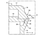
図5〜図8には、他の実施形態が示されている。図5および図6に示した実施形態では、連通孔部27が、蓋側ヒンジブロック24の当接面24cから当該蓋側ヒンジブロック24を上方に向かって貫通して蓋側ヒンジブロック24の傾斜面24bに開口される形態に代えて、蓋側ヒンジブロック24の当接面24cにその頂面24a間にわたって横方向に一連に溝部31を形成し、この溝部31を本体側ヒンジブロック23の当接面23cで塞ぐことによって形成され、貫通孔部26がこの溝部31と連通されるようになっている。
【0036】
また、図7および図8に示した実施形態では、連通孔部27が、本体側ヒンジブロック23の当接面23cにその頂面23a間にわたって横方向に一連に溝部32を形成し、この溝部32を蓋側ヒンジブロック24の当接面24cで塞ぐことによって形成され、貫通孔部26がこの溝部32と連通されるようになっている。
【0037】
いずれの実施形態にあっても、上記実施形態と同様に、流水孔25は、ヒンジブロック23,24の当接面23c,24c同士が液密に当接されることにより、貫通孔部26が溝部31,32で形成された連通孔部27に一連に接続され、これによりキャップ本体4の外筒部13内部がヒンジブロック23,24の左右の頂面23a,24aを介して外部と連通されるようになっている。
【0038】
本実施形態にあっては、流水孔25の他端を、互いに折り曲げ自在に連結された本体側ヒンジブロック23と蓋側ヒンジブロック24との間で、それらの一方に形成した溝部31,32で構成するようにしたので、蓋体5を開いたときに露出されるこの溝部31,32を清掃することが可能であり、流水孔25の目詰まりをさらに確実に防止することができる。またこの実施形態にあっては、流水孔25がヒンジ6の左右に開口されるため、蓋側ヒンジブロック24の傾斜面24bに開口される上記実施形態と比べて、流水孔25が目立つことはなく、さらに外観を向上させることができる。
【0039】
【発明の効果】
以上要するに、本発明にかかるキャップにあっては、特段蓋体に隙間などを形成するばね片等を備える必要がなく、また外観が良好であるとともに、抽出物による目詰まりも防止でき、かつまた蓋体を閉じている状態ではキャップ本体内部が外部と直接連通されることがなく、これに水が流入することを阻止することができる。
【図面の簡単な説明】
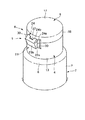
【図1】本発明にかかるキャップの好適な一実施形態を、容器本体に装着して蓋体を開いた状態で示す斜視図である。
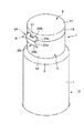
【図2】図1のキャップの蓋体を閉じた状態を示す斜視図である。
【図3】図1のキャップを閉じて、容器本体を倒立させた状態の側断面図である。
【図4】図1のキャップの変形例を示す、容器本体に装着して蓋体を閉じた状態の斜視図である。
【図5】本発明にかかるキャップの他の実施形態を示す、蓋体を開いた状態のヒンジ周辺の拡大斜視図である。
【図6】図5のキャップのヒンジ周辺を示す拡大側断面図である。
【図7】本発明にかかるキャップのさらに他の実施形態を示す、蓋体を開いた状態のヒンジ周辺の拡大斜視図である。
【図8】図7のキャップのヒンジ周辺を示す拡大側断面図である。
【符号の説明】
1 キャップ 2 容器本体
3 抽出口 4 キャップ本体
5 蓋体 6 ヒンジ
23 本体側ヒンジブロック 24 蓋側ヒンジブロック
25 流水孔 26 貫通孔部
31,32 溝部[0001]
BACKGROUND OF THE INVENTION
The present invention does not require a spring piece or the like that forms a gap or the like in the special lid body, has a good appearance, can prevent clogging due to the extract, and has a cap when the lid body is closed. The present invention relates to a cap in which the inside of the main body is not directly communicated with the outside.
[0002]
[Prior art]
Conventionally, various containers, particularly tube containers, have been known that can be placed upside down, and in this way, rather than laying the container aside. Even has the advantage of not taking up space. The cap adopted for such a container is roughly the upper part of the container body, a cap body that surrounds the periphery of the extraction port, a lid that closes the extraction port of the container body so as to be openable and closable, and the lid is the cap body. And a hinge that is pivotably connected, and the container body can be supported in an inverted state by placing the cap on the placing surface with the container body turned upside down.
[0003]
However, if you use such a container in a bathroom such as a washroom or bathroom, and leave it upside down after use, the water adhering to the container body will flow down the surface and flow down the container. There was a problem in that it flowed from between the main body and the cap main body placed on the main body and accumulated in the cap main body. For the purpose of solving such problems, for example,
[0004]
In
[0005]
In
[0006]
In
[0007]
[Patent Document 1]
Japanese Utility Model Laid-Open No. 5-72747 [Patent Document 2]
Japanese Utility Model Publication No. 6-18263 [Patent Document 3]
Japanese Patent Laid-Open No. 2001-48203
[Problems to be solved by the invention]
By the way, in the above-mentioned
[0009]
Further, in these
[0010]
On the other hand,
[0011]
The present invention was devised in view of the above-described conventional problems, and it is not necessary to provide a spring piece or the like that forms a gap or the like in the special lid body, and the appearance is good, and clogging due to the extract is also caused. An object of the present invention is to provide a cap that can be prevented and that does not allow the inside of the cap body to communicate directly with the outside when the lid is closed.
[0012]
[Means for Solving the Problems]
The cap according to the present invention includes a cap body that is placed on an upper portion of the container body so as to surround the periphery of the extraction port, a lid that closes the extraction port of the container body so as to be openable and closable, and the lid is rotated to the cap body A hinge that freely connects to the cap body and supports the container body in an inverted state while allowing water flowing into the cap body to flow out from between the container body and the hinge. A hinge block that protrudes outward from the cap body, and is formed to protrude outward from the lid and is foldably connected to the hinge block of the body. A lid-side hinge block abutting against the body-side hinge block with the extraction port closed, and between the body-side hinge block and the lid-side hinge block One end inside the cap body and the other end communicated was formed with the outside through the water flow hole.
[0013]
In the present invention, the inside and outside of the cap body are communicated with each other through a water flow hole formed between the body-side hinge block and the lid-side hinge block that project outward from the cap body and the lid body. In addition, since the water flow hole is formed in the hinge block in this way, there is no need to provide a spring piece or the like that forms a gap or the like in the lid, and of course when the lid is closed, It is not noticeable even when opened, and it is possible to obtain a good appearance, and it is possible to reduce the possibility that the extract will reach the flow hole by wiping the extract from the extraction port. It is possible to prevent the pores from being clogged with the extract.
[0014]
Further, when the extraction port is closed by the lid, the lid side hinge block is brought into contact with the body side hinge block, and the inside of the cap body is communicated with the outside only through the water flow hole. While the body is closed, the inside of the cap body can be directly communicated with the outside to prevent water from flowing into the cap body.
[0015]
Moreover, one end of the water flow hole is a through-hole portion that passes through the body-side hinge block and opens toward the inside of the cap body. The inside of the cap body is completely cut off from the outside by the through-hole when the container body is inverted, so that the body-side hinge block located above the lid-side hinge block is infiltrated from the outside. Can be more reliably prevented.
[0016]
Furthermore, the other end of the water flow hole is formed by closing a groove formed in one of the main body side hinge block and the lid side hinge block with the other. The other end of the water flow hole is composed of a groove formed on one of the main body side hinge block and the lid side hinge block that are foldably connected to each other, so that it is exposed when the lid is opened. This groove portion can be cleaned, and the clogging of the water flow holes can be more reliably prevented.
[0017]
DETAILED DESCRIPTION OF THE INVENTION
Hereinafter, a preferred embodiment of a cap according to the present invention will be described in detail with reference to the accompanying drawings. As shown in FIGS. 1 to 3, the
[0018]
The
[0019]
The
[0020]
The
[0021]
The
[0022]
The
[0023]
The
[0024]
The body-
[0025]
Furthermore, between the main body
[0026]
The through-
[0027]
The
[0028]
The operation of the
[0029]
Since the
[0030]
On the other hand, when extracting the extract from the
[0031]
In the
[0032]
Further, when the
[0033]
In particular, the inside of the
[0034]
FIG. 4 shows a modification of the above embodiment. In this modified example, a belt-like elastic piece constituting a so-called snap hinge, with a pair on both sides of the
[0035]
5 to 8 show other embodiments. In the embodiment shown in FIG. 5 and FIG. 6, the
[0036]
Further, in the embodiment shown in FIGS. 7 and 8, the
[0037]
In any embodiment, like the above-described embodiment, the flowing
[0038]
In the present embodiment, the other end of the
[0039]
【The invention's effect】
In short, the cap according to the present invention does not need to be provided with a spring piece or the like that forms a gap or the like in the special lid body, has a good appearance, can prevent clogging by the extract, and / or When the lid is closed, the inside of the cap body is not directly communicated with the outside, and water can be prevented from flowing into the cap body.
[Brief description of the drawings]
FIG. 1 is a perspective view showing a preferred embodiment of a cap according to the present invention in a state in which the cap is attached to a container body and a lid is opened.
FIG. 2 is a perspective view showing a state in which the lid of the cap of FIG. 1 is closed.
FIG. 3 is a side sectional view showing a state in which the cap body of FIG. 1 is closed and the container body is inverted.
4 is a perspective view showing a modification of the cap of FIG. 1 in a state where the cap body is mounted and the lid body is closed. FIG.
FIG. 5 is an enlarged perspective view of the vicinity of the hinge with the lid opened, showing another embodiment of the cap according to the present invention.
6 is an enlarged side sectional view showing the vicinity of the hinge of the cap of FIG. 5;
FIG. 7 is an enlarged perspective view of the vicinity of the hinge in a state where the lid is opened, showing still another embodiment of the cap according to the present invention.
8 is an enlarged side sectional view showing the vicinity of the hinge of the cap of FIG.
[Explanation of symbols]
DESCRIPTION OF
Claims (3)
上記ヒンジを、上記キャップ本体から外方へ突出させて形成された本体側ヒンジブロックと、上記蓋体から外方へ突出させて形成されかつ該本体側ヒンジブロックに折り曲げ自在に連結され、該蓋体で上記抽出口を閉じている状態で該本体側ヒンジブロックに当接される蓋側ヒンジブロックとから構成するとともに、
上記本体側ヒンジブロックと上記蓋側ヒンジブロックとの間に、上記キャップ本体内部に一端が連通され他端が外部と連通された流水孔を形成したことを特徴とするキャップ。A cap body that covers the upper part of the container body so as to surround the periphery of the extraction port, a lid that closes the extraction port of the container body so as to be openable and closable, and a hinge that pivotally connects the lid to the cap body. In a cap that allows the water flowing into the cap body to flow out from between the container body while supporting the container body in an inverted state,
A body-side hinge block formed by projecting the hinge outward from the cap body; and a body-side hinge block formed by projecting outward from the lid body and foldably connected to the body-side hinge block; A lid-side hinge block that comes into contact with the body-side hinge block while the extraction port is closed by the body,
A cap characterized in that a water flow hole having one end communicating with the inside of the cap body and the other end communicating with the outside is formed between the main body side hinge block and the lid side hinge block.
Priority Applications (1)
| Application Number | Priority Date | Filing Date | Title |
|---|---|---|---|
| JP2003044703A JP4266664B2 (en) | 2003-02-21 | 2003-02-21 | cap |
Applications Claiming Priority (1)
| Application Number | Priority Date | Filing Date | Title |
|---|---|---|---|
| JP2003044703A JP4266664B2 (en) | 2003-02-21 | 2003-02-21 | cap |
Publications (2)
| Publication Number | Publication Date |
|---|---|
| JP2004250079A true JP2004250079A (en) | 2004-09-09 |
| JP4266664B2 JP4266664B2 (en) | 2009-05-20 |
Family
ID=33027320
Family Applications (1)
| Application Number | Title | Priority Date | Filing Date |
|---|---|---|---|
| JP2003044703A Expired - Fee Related JP4266664B2 (en) | 2003-02-21 | 2003-02-21 | cap |
Country Status (1)
| Country | Link |
|---|---|
| JP (1) | JP4266664B2 (en) |
Cited By (3)
| Publication number | Priority date | Publication date | Assignee | Title |
|---|---|---|---|---|
| JP2009096478A (en) * | 2007-10-15 | 2009-05-07 | Lion Corp | Cap for inverted container |
| JP2011051612A (en) * | 2009-08-31 | 2011-03-17 | Yoshino Kogyosho Co Ltd | Pouring cap |
| JP2013079083A (en) * | 2011-09-30 | 2013-05-02 | Yoshino Kogyosho Co Ltd | Spouting cap |
-
2003
- 2003-02-21 JP JP2003044703A patent/JP4266664B2/en not_active Expired - Fee Related
Cited By (3)
| Publication number | Priority date | Publication date | Assignee | Title |
|---|---|---|---|---|
| JP2009096478A (en) * | 2007-10-15 | 2009-05-07 | Lion Corp | Cap for inverted container |
| JP2011051612A (en) * | 2009-08-31 | 2011-03-17 | Yoshino Kogyosho Co Ltd | Pouring cap |
| JP2013079083A (en) * | 2011-09-30 | 2013-05-02 | Yoshino Kogyosho Co Ltd | Spouting cap |
Also Published As
| Publication number | Publication date |
|---|---|
| JP4266664B2 (en) | 2009-05-20 |
Similar Documents
| Publication | Publication Date | Title |
|---|---|---|
| RU2004107793A (en) | COOKING TOOL INDICATING AN UNAUTHORIZED OPENING | |
| JP4266664B2 (en) | cap | |
| KR20090000673U (en) | A tumbler with filter net container | |
| JP4266665B2 (en) | cap | |
| JP3929602B2 (en) | Pouring tap with lid of shaking container | |
| JP4266663B2 (en) | cap | |
| JP2981439B2 (en) | Hydraulic oil tank for construction machinery | |
| JP2008162673A (en) | Cap and inversely-standable container having the same | |
| JPH09316957A (en) | Hop-up type drain cock | |
| JP2004250077A (en) | Cap | |
| JP3320908B2 (en) | Inverted tube container | |
| KR200190169Y1 (en) | The lid convenient of open and shut, and the straw adhere to stopper | |
| JP4141668B2 (en) | Spout cap | |
| KR200436933Y1 (en) | oral cavity waste liquid collection bottle | |
| JP2002154571A (en) | Hinged cap | |
| KR200366144Y1 (en) | Joint Structure of Case and Cradle for Case | |
| JP3816207B2 (en) | Liquid pouring tool | |
| JP4165631B2 (en) | Hinge cap | |
| JP2001048203A (en) | Container cap | |
| JP2002285604A (en) | Drain structure of water-proof pan | |
| JP3864272B2 (en) | Hinge cap | |
| JPH076222Y2 (en) | Structure of drain plug | |
| JP4530553B2 (en) | Pneumatic pot | |
| JPH0428528Y2 (en) | ||
| JP6537174B2 (en) | Hinged cap |
Legal Events
| Date | Code | Title | Description |
|---|---|---|---|
| A621 | Written request for application examination |
Free format text: JAPANESE INTERMEDIATE CODE: A621 Effective date: 20060125 |
|
| A977 | Report on retrieval |
Free format text: JAPANESE INTERMEDIATE CODE: A971007 Effective date: 20081028 |
|
| A131 | Notification of reasons for refusal |
Free format text: JAPANESE INTERMEDIATE CODE: A131 Effective date: 20081104 |
|
| A521 | Written amendment |
Free format text: JAPANESE INTERMEDIATE CODE: A523 Effective date: 20081226 |
|
| TRDD | Decision of grant or rejection written | ||
| A01 | Written decision to grant a patent or to grant a registration (utility model) |
Free format text: JAPANESE INTERMEDIATE CODE: A01 Effective date: 20090203 |
|
| A01 | Written decision to grant a patent or to grant a registration (utility model) |
Free format text: JAPANESE INTERMEDIATE CODE: A01 |
|
| A61 | First payment of annual fees (during grant procedure) |
Free format text: JAPANESE INTERMEDIATE CODE: A61 Effective date: 20090217 |
|
| R150 | Certificate of patent or registration of utility model |
Ref document number: 4266664 Country of ref document: JP Free format text: JAPANESE INTERMEDIATE CODE: R150 Free format text: JAPANESE INTERMEDIATE CODE: R150 |
|
| FPAY | Renewal fee payment (event date is renewal date of database) |
Free format text: PAYMENT UNTIL: 20120227 Year of fee payment: 3 |
|
| FPAY | Renewal fee payment (event date is renewal date of database) |
Free format text: PAYMENT UNTIL: 20130227 Year of fee payment: 4 |
|
| R250 | Receipt of annual fees |
Free format text: JAPANESE INTERMEDIATE CODE: R250 |
|
| FPAY | Renewal fee payment (event date is renewal date of database) |
Free format text: PAYMENT UNTIL: 20140227 Year of fee payment: 5 |
|
| R250 | Receipt of annual fees |
Free format text: JAPANESE INTERMEDIATE CODE: R250 |
|
| R250 | Receipt of annual fees |
Free format text: JAPANESE INTERMEDIATE CODE: R250 |
|
| R250 | Receipt of annual fees |
Free format text: JAPANESE INTERMEDIATE CODE: R250 |
|
| R250 | Receipt of annual fees |
Free format text: JAPANESE INTERMEDIATE CODE: R250 |
|
| R250 | Receipt of annual fees |
Free format text: JAPANESE INTERMEDIATE CODE: R250 |
|
| R250 | Receipt of annual fees |
Free format text: JAPANESE INTERMEDIATE CODE: R250 |
|
| LAPS | Cancellation because of no payment of annual fees |