JP2004250042A - Cap of excellent detection characteristic for cap seaming position - Google Patents
Cap of excellent detection characteristic for cap seaming position Download PDFInfo
- Publication number
- JP2004250042A JP2004250042A JP2003042051A JP2003042051A JP2004250042A JP 2004250042 A JP2004250042 A JP 2004250042A JP 2003042051 A JP2003042051 A JP 2003042051A JP 2003042051 A JP2003042051 A JP 2003042051A JP 2004250042 A JP2004250042 A JP 2004250042A
- Authority
- JP
- Japan
- Prior art keywords
- cap
- bottle
- mark
- image
- top plate
- Prior art date
- Legal status (The legal status is an assumption and is not a legal conclusion. Google has not performed a legal analysis and makes no representation as to the accuracy of the status listed.)
- Pending
Links
Images


Landscapes
- Closures For Containers (AREA)
Abstract
Description
【0001】
【発明の属する技術分野】
本発明は、ボトルの首部にキャップが螺子装着(巻締)されたボトル・キャップ組立体に関して、キャップ巻締位置の確認によりキャップの締結状態の検査を確実に行なうことが可能なキャップに関する。
【0002】
【従来の技術】
ガラス製或いは合成樹脂製のボトル形状容器と、一旦開封されたものであることを明示するタンパーエビデント機能を有するキャップから成るボトル・キャップ組立体においては、内容物充填後に、キャップがボトルに完全に密封状態に締結されていることが必須であり、このような検査は、従来は、製品の中からいくつかの試料を抜き取り、これを実際に開栓し、開栓トルク、巻締角度等を測定することによって行っていた。
しかしながら、このような抜き取り検査は製品の一部について行うにすぎず、必ずしも確実な検査結果を得ることは困難であり、また検査の確実性を向上させるために抜き取り試料を多くすればそれだけ生産コストが増加することになる。
また巻締機を最初に設定する際に、基本的な性能を出すための巻締角度に従ってトルクが決定されているため、巻締め角度を容易に測定できることが望まれている。
【0003】
このような問題を解決するために、キャップの天板周縁部にキャップ巻締位置確認マーク(キャップマーク)を設け、またボトルのサポートリングの上面にはキャップ巻締位置を確認するためのボトル位置確認マーク(ボトルマーク)を設け、このようなボトルにキャップが巻締められたボトル・キャップ組立体の上方に一台のカメラを配置し、このカメラによってキャップマーク及びボトルマークを同時に撮影し、映像データを画像処理してボトルマークに対するキャップマークの位置を検出することにより、キャップの巻締状態を検査する方法が開示されている。このような検査方法において、ボトルのサポートリング上面のボトルマーク及びキャップマークは、凹部或いは切欠きとして形成されている(特許文献1参照)。
【0004】
【特許文献1】
特開2003−2310号公報
【0005】
【発明が解決しようとする課題】
上記の従来技術によれば、試料の抜き取り及び実際の開栓という検査方法によらずに、一台のカメラによる映像に基づく画像処理によってボトル・キャップ組立体の締結状態を確認することが可能となる。
【0006】
しかしながら、上記検査方法では、ボトルマークとキャップマークとが鮮明に撮像されることが必要である。ボトルマークは、カメラで捉えられるボトル・キャップ組立体の映像の輪郭部分に位置するため、例えばサポートリングが透明であるか或いは不透明であるかによって撮像に際しての照明条件を変えることにより、映像として鮮明に捉え易いが、キャップマークは、ボトル・キャップ組立体の映像の内部に位置しているため、映像として鮮明に捉えにくいという問題があった。
【0007】
即ち、キャップマークを映像として鮮明に捉えるためには、キャップマークが影として鮮明に映し出されればよいのであるが、通常の凹部或いは切欠きとして形成されているキャップマークでは、ボトルマークを鮮明に映し出すための照明条件の変更や、生産過程でボトル或いはキャップに付着した水滴などの影響で、マークが形成されていない他の部分との輝度の差が小さくなってしまい、その映像が不鮮明となってしまうのである。
【0008】
従って、本発明の目的は、キャップに形成されているキャップの巻締位置確認マークを、上方に配置された一台のカメラによって鮮明に映像として捉えることができ、ボトルに巻締められたキャップの巻締位置を精度よく検査することが可能なキャップを提供することにある。
【0009】
【課題を解決するための手段】
本発明によれば、天板と天板周縁から降下したスカート状側壁とを有しており、スカート状側壁の内面には容器首部の外面と係合する螺条を備え、該天板周縁部分にはキャップ巻締角度確認マークが設けられているキャップにおいて、前記キャップ巻締角度確認マークは、凹部と該凹部の底部に形成された凸部とから構成されていることを特徴とするキャップが提供される。
【0010】
【発明の実施形態】
以下、本発明を添付図面に示す具体例に基づいて詳細に説明する。
図1は、本発明のキャップの代表的な構造を示す一部断面側面図であり、
図2は、図1のキャップの上面図であり、
図3は、図1のキャップに形成されているキャップ巻締位置確認マークの形状の例を示す図であり、
図4は、図1のキャップに形成されているキャップ巻締位置確認マークのカメラ映像を、従来例のキャップに形成されているキャップ巻締位置確認マークのカメラ映像と比較して説明するための図であり、
図5は、図1のキャップが装着されるボトルに形成されるボトル位置確認マークの位置を説明するための図であり、
図6は、図1のキャップがボトルに装着されたボトル・キャップ組立体の上面図であり、
図7は、図1のキャップがボトルに装着されたボトル・キャップ組立体についての巻締状態の検査を実施するための装置の配置図であり、
図8は、図7の装置で実施される検査のフローチャートである。
【0011】
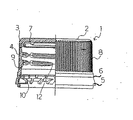
本発明のキャップの一例を示す図1及び図2において、全体を1で表すキャップは、天板2及び天板2の周縁に位置するコーナー部3を介して垂下するスカート状側壁4から成っており、スカート状側壁4の下端には、タンパーエビデント(TE)バンド5が弱化部6を介して設けられている。
【0012】
キャップ天板2の内面には、ライナー材7が形成され、ライナー材の外周凸部がボトル口部外面と接触し、容器の密封性を高めるように設けられている。また、スカート状側壁4の外面には把持しやすいようにローレット溝8が設けられ、内面には、後述するボトル首部外面に設けられたネジ部21(図5参照)と螺合するネジ部9が形成されている。
【0013】
更に、TEバンド5の内面には、後述するボトルの段差部22(図5参照)と係合してTEバンド5を固定するためのフラップ片10が設けられている。
【0014】
図2に示されているように、キャップの天板2の周縁部にキャップ巻締位置確認マーク(キャップマーク)11が設けられているが、本発明では、上方に配置されたカメラでの撮像により、このキャップマーク11が鮮明な映像として捉えられるような形状に設計されている。
【0015】
即ち、図3(a)及び図3(b)に示したように、本発明のキャップにおけるキャップマーク11は、凹部11aと凹部11aの底部に形成された凸部11bとから構成されている。この凸部11bの形状は、図3(a)に示されているように上端がフラットな平面であってもよいし、また上端が尖った形状となっていてもよい。キャップ11をこのような形態とすることにより、凸部11bの周囲の凹部11aに入射する光量が著しく制限されることになり、これを上方からのカメラで撮像した場合、鮮明な映像として捉えることが可能となる。
【0016】
例えば、図4(b)は、キャップマーク11が単なる凹部のみから形成されているキャップマーク11のカメラ映像を示すものであるが、マーク11の全体が薄い影となって映し出される。したがって、撮像に際しての照明条件の変更や水滴などが付着していた場合には、このキャップマーク11の映像が不鮮明となってしまう。
【0017】
一方、本発明にしたがい、凹部11aの底部に凸部11bを設けることによってキャップマーク11を形成した場合には、上方からのカメラ映像は、図4(a)に示すように、凸部11bの部分が明るく、その周縁が濃い影となったリングとして鮮明に映し出される。従って、照明条件の変更や水滴などの付着が合った場合にも、その影響が極めて少なく、キャップマーク11を常に鮮明な映像として捉えることが可能となるものである。
【0018】
本発明において、凹部11aの大きさは、特に制限されるものではないが、あまり大きいとキャップの外観を損ねてしまい、またあまり小さいと凸部11bの形成が困難になるため、通常は、その外径を0.5乃至2.0mm程度にするのが好ましい。また、凹部11aの深さは、天板2を貫通してしまわない程度であればよいが、通常は、少なくとも0.3mm以上あるのがよい。凹部11aが浅いと、その影が薄くなるおそれがあるためである。
【0019】
凸部11bと凹部11aの外周との間隔(図3(a)でdで示す)は、0.2乃至0.5mm程度がよい。即ち、この間隔dがあまり大きいと、その影が薄くなってしまい、一方、間隔dがあまり小さいと、影が細くなってしまい、その認識が困難となるおそれがあるためである。凸部11bの高さは、ある程度の高さを有していればよいが、外観が損なわれないように、凹部11aから突出しない程度の高さとするのがよい。
【0020】
また、図4では、凹部11a及び凸部11bの上面からみた形状が何れも円形で示されているが、影が明確に映し出される限りにおいて、その形状に制限はなく、何れも上面からみた形状が、例えば四角形であってもよい。
【0021】
上述したキャップマーク11を有するキャップがボトルに装着されたボトル・キャップ組立体についてのキャップ巻締状態の検査は、前述した特許文献1に記載と同様の原理で行われる。即ち、一台のカメラにより、ボトル・キャップ組立体を上方から撮影し、ボトルのサポートリングに形成されているボトル位置確認マーク(ボトルマーク)と上記キャップマーク11とを同時に映像として取り込み、両者の相対的位置関係から、キャップの巻き締め角度を検出する。
【0022】
例えば、上記ボトルの首部を示す図5において、この首部外面には、キャップと螺合してボトルを密封するためのネジ部21が形成されており、ネジ部21の下方には、キャップ1のTEバンド5のフラップ片10と係合する段差部22が形成されている。また段差部22の下側には充填や密封の際に、ボトルを保持するためのサポートリング23が形成されている。
このサポートリング23は、キャップ或いはTEバンドの下端の最も大きい外径部分にほぼ匹敵するか或いはそれよりも大きい外径を有している。
尚、図5には示されていないが、このボトルの口部は、通常のボトルと同様に、肩部、胴部、および底部に一体に接続されている。
【0023】
上記のボトルにおいて、サポートリング23の表面には、凹部或いは凸部から形成されているボトル位置確認マーク(ボトルマーク)24が設けられている。即ち、ボトル・キャップ組立体を上方に配置されたカメラで撮像し、取り込んだ映像から、前述したキャップマーク11とボトルマーク24との相対的位置関係からキャップの巻き締め状態が検出される。なお、ボトルマーク24の形状等は特に制限されないが、通常、これを形成する凸部或いは凹部の幅が1.0乃至4.5mm程度とするのがよく、また、そのマーク形状は平行な幅の凹部、三角形の凹部乃至凸部、或いは台形の凹部などの形状とすることができる。
【0024】
上述したキャップマーク11及びボトルマーク24の周方向位置は、巻締角度の検出が容易になるように、種々の位置に設定することができる。例えば、図5に示されているように、ボトルマーク24は、ボトル首部に設けられたネジ部21の始端位置、すなわちキャップとの螺合開始位置25に対応する、サポートリング23の外周部に設けることができる。また、キャップマーク11は、スカート部4内面に設けられたネジ部の始端位置、すなわちボトルとの螺合開始位置12(図1参照)に対応する、キャップ天板2の周縁部に設けることができる。
【0025】
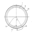
更に図6は、上述した本発明のキャップがボトルに装着されたボトル・キャップ組立体の一例を示す平面図であり、例えば、キャップ1は、図の矢印Xの方向に回転することにより巻き締められるようになっている。
図6に示されているように、マーク11及び24によって形成される巻締角度を容易に測定するために、キャップ天板2の中心に補助マーク13を設けることもできる。この補助マーク13も、キャップマーク11と同様、凹部の底部に凸部を形成することにより構成したものであるのがよい。これにより、ボトル・キャップ組立体の巻締角度は、キャップマーク11,補助マーク13,ボトルマーク24によって容易に測定することができる。
【0026】
上述した本発明において、キャップとしては、ポリエチレン、ポリプロピレン等のオレフィン系樹脂や、塩化ビニル樹脂等の合成樹脂を圧縮成形、射出成形等して得られるキャップの他、キャッピング前にネジやラグが形成された金属製のキャップでもよい。更に、キャップ下端には、TEバンドが弱化部を介して一体に設けられているキャップであることが好ましいが、巻締め後シュリンクフィルムで覆うような場合には、TEバンドのないキャップにも適用することが可能である。
【0027】
また、上記キャップに組み合わされるボトルとしては、ポリエチレンテレフタレート等の合成樹脂から成る延伸ブローボトルや、射出成形等によるボトル等に好適に用いることができるが、勿論、ガラス製ボトルにも適用することができる。
【0028】
上述したボトル・キャップ組立体を用いての検査を実施するための検査装置の一例の配置を示す図7において、ボトル・キャップ組立体30の垂直軸上方に、光学系レンズ40と、前記確認マーク11、24を撮像するためのCCD撮像素子を備えたカメラ50とが、前記組立体30の垂直軸と光学系の光軸とが一致するように配置されている。
また、カメラ50は、下端部が開口している筒状のフード51内に収納されており、このフード51の開口部中心には、上記のレンズ40及びキャップマーク11、ボトルマーク24を照明するための照明装置60が配置されており、レンズ40とカメラ50との間の光路は、筒状フード51によって覆われている。
【0029】
更に、カメラ50からケーブル52を介して送られる画像データを処理するための画像処理装置(画像処理コンピュータ)70および画像データおよび検査結果を表示するためのモニター75が配置されている。
【0030】
図に示した具体例において、レンズ40はキャップの径よりも大きい径を有する平凸レンズであり、キャップの径の約3倍程度の径を有しており、平凸レンズの平らな面がボトル・キャップ組立体の側に面している。平凸レンズの径はキャップの径の約2乃至4倍の径を有しているのが適当である。平凸レンズの代わりにメニスカス凸レンズを用いて、ボトルマーク24からの集光力をより高めることもできる。
【0031】
また、照明装置60としては、光路調整を容易に行い得るように、LEDなどを用いることが好ましい。例えば、ボトルのサポートリング23が透明である場合には、ボトルの内部に収容されている液体からの反射によるハレーションを防止するために、キャップ1のスカート状側壁8に光が直接照射されるように設定しておくことが好ましい。また、サポートリング23が不透明である場合には、サポートリング23に直接光が照射されるように光路を設定しておくことが好適である。
【0032】
上述したキャップマーク11およびボトルマーク24は、レンズ40により、カメラ50のCCD素子上に結像する。
【0033】
上記のようにして映像として取り込まれたキャップマーク11及びボトルマーク24の像に基づくボトル・キャップ組立体の巻締角度の検査は、画像処理装置(画像処理コンピュータ)70とカメラ50との間で、図8に示すフローチャートに基づいて行われる。
まず、検査装置の運転信号を検出し、この運転信号を検出した後、カメラ50からのボトル・キャップ組立体の検出信号を待つ。この検出信号があり次第、カメラ50による画像データが画像処理装置(画像処理コンピュータ)70に取り入れられる。この画像データに基づいて、ボトル・キャップ組立体の中心が検出される。この中心の検出は、キャップ天板2の中心に設けられた補助マーク13(図6)によって行ってもよいし、また補助マークがない場合にはキャップ天板2の円周から芯出しを行ってもよい。
中心の検出が行われた後、二次元座標上の画像データを、例えば特許文献1に記載されているように極座標に展開し、キャップマーク11とボトルマークとを検出する。
極座標上で検出されたキャップマーク11とボトルマーク24の位置から、直ちに両者の角度あるいは距離が算出され、測定で検出される巻締角度を、設定巻締角度に対比し、巻締状態の良否を検出する。すなわち、角度が所定の範囲外であれば、不良を表示し、範囲内であれば、次の測定に戻る。
【0034】
なお、上記の実施形態では、キャップ巻締角度確認マークを、キャップの天板周縁部分に設けた場合について説明を行ったが、キャップのスカート状側壁部分にマークを設けた場合にも同様の効果を得ることができる。
【0035】
【発明の効果】
本発明によれば、キャップに形成されているキャップの巻締位置確認マークを、上方に配置された一台のカメラによって鮮明に映像として捉えることができ、ボトルに巻締められたキャップの巻締位置を精度よく検査することができる。
【図面の簡単な説明】
【図1】本発明のキャップの代表的な構造を示す一部断面側面図。
【図2】図1のキャップの上面図。
【図3】図1のキャップに形成されているキャップ巻締位置確認マークの形状の例を示す図。
【図4】図1のキャップに形成されているキャップ巻締位置確認マークのカメラ映像を、従来例のキャップに形成されているキャップ巻締位置確認マークのカメラ映像と比較して説明するための図。
【図5】図1のキャップが装着されるボトルに形成されるボトル位置確認マークの位置を説明するための図。
【図6】図1のキャップがボトルに装着されたボトル・キャップ組立体の上面図。
【図7】図1のキャップがボトルに装着されたボトル・キャップ組立体についての巻締状態の検査を実施するための装置の一例の配置図。
【図8】図7の装置で実施される検査のフローチャート。
【符号の説明】
1:キャップ
2:天板
11:キャップマーク
23:サポートリング
24:ボトルマーク[0001]
TECHNICAL FIELD OF THE INVENTION
TECHNICAL FIELD The present invention relates to a cap capable of reliably performing an inspection of a tightened state of a cap by confirming a cap tightening position of a bottle-cap assembly in which a cap is screwed (tightened) to a neck portion of the bottle.
[0002]
[Prior art]
In a bottle-cap assembly composed of a glass or synthetic resin bottle-shaped container and a cap having a tamper-evident function that indicates that the bottle has been opened once, the cap is completely attached to the bottle after filling the contents. Conventionally, such inspections are performed by extracting several samples from the product, opening the actual sample, opening the opening torque, tightening angle, etc. Was measured.
However, such a sampling inspection is performed only on a part of the product, and it is difficult to always obtain a reliable inspection result. Will increase.
In addition, when the winding machine is initially set, the torque is determined according to the tightening angle for achieving the basic performance. Therefore, it is desired that the winding angle can be easily measured.
[0003]
In order to solve such problems, a cap tightening position confirmation mark (cap mark) is provided on the periphery of the top plate of the cap, and a bottle position for checking the cap tightening position is provided on the upper surface of the support ring of the bottle. A confirmation mark (bottle mark) is provided, and one camera is placed above the bottle-cap assembly in which the cap is wound around such a bottle, and the cap mark and the bottle mark are simultaneously photographed by this camera, and the image is taken. There is disclosed a method of inspecting a tightened state of a cap by image-processing data and detecting a position of a cap mark with respect to a bottle mark. In such an inspection method, the bottle mark and the cap mark on the upper surface of the support ring of the bottle are formed as recesses or cutouts (see Patent Document 1).
[0004]
[Patent Document 1]
JP-A-2003-2310
[Problems to be solved by the invention]
According to the above conventional technology, it is possible to confirm the fastening state of the bottle / cap assembly by image processing based on an image by one camera without using the inspection method of extracting the sample and actually opening the bottle. Become.
[0006]
However, in the above inspection method, it is necessary that the bottle mark and the cap mark are clearly imaged. Since the bottle mark is located at the outline of the image of the bottle-cap assembly captured by the camera, for example, by changing the lighting conditions at the time of imaging depending on whether the support ring is transparent or opaque, it is sharp as an image. However, since the cap mark is located inside the image of the bottle / cap assembly, there has been a problem that it is difficult to clearly capture the image as an image.
[0007]
That is, in order to clearly capture the cap mark as an image, the cap mark only needs to be clearly projected as a shadow. Due to the change of lighting conditions and the effect of water droplets attached to the bottle or cap during the production process, the difference in brightness from other parts where no mark is formed becomes small, and the image becomes unclear. It will be lost.
[0008]
Therefore, an object of the present invention is to enable a single camera disposed above to clearly capture the image of the cap tightening position mark formed on the cap, and to provide a clear image of the cap wound around the bottle. An object of the present invention is to provide a cap capable of accurately inspecting a winding position.
[0009]
[Means for Solving the Problems]
According to the present invention, it has a top plate and a skirt-like side wall descended from the periphery of the top plate, and an inner surface of the skirt-like side wall has a thread engaging with an outer surface of a container neck portion. A cap provided with a cap tightening angle confirmation mark, wherein the cap tightening angle confirmation mark comprises a concave portion and a convex portion formed at the bottom of the concave portion. Provided.
[0010]
DETAILED DESCRIPTION OF THE INVENTION
Hereinafter, the present invention will be described in detail based on specific examples shown in the accompanying drawings.
FIG. 1 is a partial cross-sectional side view showing a typical structure of the cap of the present invention,
FIG. 2 is a top view of the cap of FIG.
FIG. 3 is a diagram showing an example of the shape of a cap tightening position confirmation mark formed on the cap of FIG.
FIG. 4 is a view for explaining a camera image of a cap tightening position confirmation mark formed on the cap of FIG. 1 in comparison with a camera image of a cap tightening position confirmation mark formed on a conventional cap. FIG.
FIG. 5 is a diagram for explaining the position of a bottle position confirmation mark formed on the bottle to which the cap of FIG. 1 is attached;
FIG. 6 is a top view of the bottle cap assembly with the cap of FIG. 1 mounted on the bottle;
FIG. 7 is a layout view of an apparatus for performing an inspection of a closed state of a bottle-cap assembly in which the cap of FIG. 1 is mounted on a bottle;
FIG. 8 is a flowchart of the inspection performed by the apparatus of FIG.
[0011]
1 and 2 showing an example of the cap of the present invention, the cap generally denoted by 1 is composed of a
[0012]
A
[0013]
Further, on the inner surface of the TE band 5, a
[0014]
As shown in FIG. 2, a cap tightening position confirmation mark (cap mark) 11 is provided on the periphery of the
[0015]
That is, as shown in FIGS. 3A and 3B, the
[0016]
For example, FIG. 4B shows a camera image of the
[0017]
On the other hand, according to the present invention, when the
[0018]
In the present invention, the size of the concave portion 11a is not particularly limited, but if it is too large, the appearance of the cap is impaired, and if it is too small, it becomes difficult to form the
[0019]
The distance between the
[0020]
Further, in FIG. 4, the shapes of the concave portions 11 a and the
[0021]
Inspection of the cap-tightened state of the bottle-cap assembly in which the cap having the
[0022]
For example, in FIG. 5 showing the neck portion of the bottle, a
The
Although not shown in FIG. 5, the mouth of the bottle is integrally connected to the shoulder, the body, and the bottom similarly to a normal bottle.
[0023]
In the above-mentioned bottle, a bottle position confirmation mark (bottle mark) 24 formed from a concave portion or a convex portion is provided on the surface of the
[0024]
The circumferential positions of the
[0025]
FIG. 6 is a plan view showing an example of a bottle-cap assembly in which the above-mentioned cap of the present invention is mounted on a bottle. For example, the
As shown in FIG. 6, an auxiliary mark 13 can be provided at the center of the cap
[0026]
In the present invention described above, as the cap, other than a cap obtained by compression molding, injection molding, or the like of an olefin resin such as polyethylene or polypropylene, or a synthetic resin such as vinyl chloride resin, screws or lugs are formed before capping. Metal caps may be used. Further, it is preferable that a TE band is provided integrally with a TE band at the lower end of the cap via a weakened portion. However, in a case where the TE band is covered with a shrink film after tightening, it is also applicable to a cap without a TE band. It is possible to do.
[0027]
Further, as a bottle to be combined with the cap, a stretch blow bottle made of a synthetic resin such as polyethylene terephthalate, a bottle made by injection molding or the like can be suitably used. it can.
[0028]
In FIG. 7 showing an arrangement of an example of an inspection apparatus for performing an inspection using the above-described bottle / cap assembly, an
The camera 50 is housed in a
[0029]
Further, an image processing device (image processing computer) 70 for processing image data sent from the camera 50 via the
[0030]
In the specific example shown in the figure, the
[0031]
Further, as the
[0032]
The
[0033]
The inspection of the tightening angle of the bottle-cap assembly based on the images of the
First, the operation signal of the inspection device is detected, and after detecting the operation signal, the detection signal of the bottle / cap assembly from the camera 50 is waited. As soon as this detection signal is received, the image data from the camera 50 is taken into the image processing device (image processing computer) 70. The center of the bottle / cap assembly is detected based on the image data. The detection of the center may be performed by an auxiliary mark 13 (FIG. 6) provided at the center of the cap
After the center is detected, the image data on the two-dimensional coordinates is developed into polar coordinates, for example, as described in
From the positions of the
[0034]
In the above embodiment, the case where the cap tightening angle confirmation mark is provided on the periphery of the top plate of the cap has been described. However, the same effect can be obtained when the mark is provided on the skirt-shaped side wall of the cap. Can be obtained.
[0035]
【The invention's effect】
ADVANTAGE OF THE INVENTION According to this invention, the fastening position confirmation mark of the cap formed in the cap can be caught as a clear image by one camera arrange | positioned above, and the fastening of the cap wound around the bottle can be performed. The position can be inspected with high accuracy.
[Brief description of the drawings]
FIG. 1 is a partial cross-sectional side view showing a typical structure of a cap according to the present invention.
FIG. 2 is a top view of the cap of FIG.
FIG. 3 is a diagram showing an example of the shape of a cap tightening position confirmation mark formed on the cap of FIG. 1;
FIG. 4 is a view for comparing a camera image of a cap tightening position confirmation mark formed on the cap of FIG. 1 with a camera image of a cap tightening position confirmation mark formed on a conventional cap. FIG.
FIG. 5 is a view for explaining the position of a bottle position confirmation mark formed on the bottle to which the cap of FIG. 1 is attached.
FIG. 6 is a top view of the bottle-cap assembly in which the cap of FIG. 1 is mounted on the bottle.
7 is a layout view of an example of an apparatus for performing an inspection of a tightened state of a bottle-cap assembly in which the cap of FIG. 1 is mounted on a bottle.
FIG. 8 is a flowchart of an inspection performed by the apparatus of FIG. 7;
[Explanation of symbols]
1: Cap 2: Top plate 11: Cap mark 23: Support ring 24: Bottle mark
Claims (1)
Priority Applications (1)
| Application Number | Priority Date | Filing Date | Title |
|---|---|---|---|
| JP2003042051A JP2004250042A (en) | 2003-02-20 | 2003-02-20 | Cap of excellent detection characteristic for cap seaming position |
Applications Claiming Priority (1)
| Application Number | Priority Date | Filing Date | Title |
|---|---|---|---|
| JP2003042051A JP2004250042A (en) | 2003-02-20 | 2003-02-20 | Cap of excellent detection characteristic for cap seaming position |
Publications (1)
| Publication Number | Publication Date |
|---|---|
| JP2004250042A true JP2004250042A (en) | 2004-09-09 |
Family
ID=33025433
Family Applications (1)
| Application Number | Title | Priority Date | Filing Date |
|---|---|---|---|
| JP2003042051A Pending JP2004250042A (en) | 2003-02-20 | 2003-02-20 | Cap of excellent detection characteristic for cap seaming position |
Country Status (1)
| Country | Link |
|---|---|
| JP (1) | JP2004250042A (en) |
Cited By (1)
| Publication number | Priority date | Publication date | Assignee | Title |
|---|---|---|---|---|
| JP2010070230A (en) * | 2008-09-19 | 2010-04-02 | Nihon Yamamura Glass Co Ltd | Cap |
-
2003
- 2003-02-20 JP JP2003042051A patent/JP2004250042A/en active Pending
Cited By (1)
| Publication number | Priority date | Publication date | Assignee | Title |
|---|---|---|---|---|
| JP2010070230A (en) * | 2008-09-19 | 2010-04-02 | Nihon Yamamura Glass Co Ltd | Cap |
Similar Documents
| Publication | Publication Date | Title |
|---|---|---|
| US6643009B2 (en) | Method of inspecting a wrap-fitted state of a cap wrap-fitted to a neck of a bottle and apparatus therefor | |
| JP5090087B2 (en) | Cap winding angle inspection device for bottle and cap assembly | |
| JPH09169392A (en) | Image type capping state tester | |
| KR101690397B1 (en) | Method and apparatus for checking a screw closure torque without contact | |
| US5699152A (en) | Electro-optical inspection system and method | |
| EP2719996B1 (en) | Apparatus for inspecting a bottle can thread | |
| FI98762C (en) | Inspection of the container's surface treatment | |
| US8937656B2 (en) | Method and inspection device for testing containers | |
| CN1131740A (en) | Optical inspection of container finish dimensional parameters | |
| JPH10505680A (en) | Container flange inspection system using an annular lens | |
| CN116075715A (en) | Device and method for inspecting closed containers | |
| CN111164644A (en) | Method and device for detecting the angular position of a bottle cap relative to a bottle | |
| US7009697B2 (en) | Method of monitoring closures on containers | |
| JP2003002311A (en) | Inspection method for bottle.cap assembly and apparatus for the same | |
| JP4798883B2 (en) | Inspection method and apparatus for bottle cap assembly | |
| JP4217399B2 (en) | Bottle cap assembly inspection device | |
| JP4547073B2 (en) | Bottle cap assembly and fastening state inspection method | |
| JP2004250042A (en) | Cap of excellent detection characteristic for cap seaming position | |
| JP3966737B2 (en) | Inspection method of cap tightness in bottle and cap assembly | |
| JPH04231854A (en) | Inspection for crack in container | |
| JP4485721B2 (en) | Inspection method of bottle cap assembly | |
| JP3910869B2 (en) | Cap winding condition detection method | |
| JP2009174928A (en) | Shrink visual inspection method | |
| JP4018391B2 (en) | Cap winding system and cap winding method | |
| JP2018203356A (en) | Detection method of displacement of cap, cap, and detection unit of displacement of cap |
Legal Events
| Date | Code | Title | Description |
|---|---|---|---|
| A621 | Written request for application examination |
Free format text: JAPANESE INTERMEDIATE CODE: A621 Effective date: 20051031 |
|
| A977 | Report on retrieval |
Free format text: JAPANESE INTERMEDIATE CODE: A971007 Effective date: 20081008 |
|
| A131 | Notification of reasons for refusal |
Free format text: JAPANESE INTERMEDIATE CODE: A131 Effective date: 20081021 |
|
| A521 | Written amendment |
Free format text: JAPANESE INTERMEDIATE CODE: A523 Effective date: 20081219 |
|
| A02 | Decision of refusal |
Free format text: JAPANESE INTERMEDIATE CODE: A02 Effective date: 20090901 |