JP2004249062A - Rope winder for safety belt - Google Patents
Rope winder for safety belt Download PDFInfo
- Publication number
- JP2004249062A JP2004249062A JP2003095312A JP2003095312A JP2004249062A JP 2004249062 A JP2004249062 A JP 2004249062A JP 2003095312 A JP2003095312 A JP 2003095312A JP 2003095312 A JP2003095312 A JP 2003095312A JP 2004249062 A JP2004249062 A JP 2004249062A
- Authority
- JP
- Japan
- Prior art keywords
- rope
- safety belt
- winder
- reels
- ropes
- Prior art date
- Legal status (The legal status is an assumption and is not a legal conclusion. Google has not performed a legal analysis and makes no representation as to the accuracy of the status listed.)
- Pending
Links
Images


Abstract
Description
【0001】
【発明の属する技術分野】
本発明は、建設工事現場等の高所作業において作業者が使用する安全帯のロープ巻取器に関するものである。
【0002】
【従来の技術】
一般に、工事現場等の高所で作業を行う場合、作業者には転落防止のための安全帯の着用が義務づけられている。この安全帯は所定長さのロープを有し、ロープの先端に取付けられた繋止用フックを作業現場の親綱等に掛けることにより、万一の転落の際に作業者をロープで支えるようにしている。
【0003】
ところで、工事現場等では、作業者が作業場所を移動する際、安全帯のロープのフックを一旦親綱から外し、移動先の作業場所で再度フックを親綱に掛けなければならないが、フックの掛け替え中は一時的であってもフックが親綱から外されるため、墜落防止に対する安全性が万全とはいえない。そこで、例えば特許文献1に記載されているように、先端にそれぞれフックを有する計2本のロープを備えた安全帯を使用すれば、フックを掛け替える場合でも、一方のロープのフックを親綱に繋止したまま他方のロープのフックを親綱に掛けた後、一方のロープのフックを親綱から外すことにより、常に何れか一方のロープを親綱に繋止させておくことができる。
【0004】
【特許文献1】
実開平7−33360号公報
【特許文献2】
特開平8−89592号公報
【0005】
【発明が解決しようとする課題】
しかしながら、前記従来例では、所定長さの各ロープをそれぞれ安全帯のベルトに連結しているため、使用していない方のロープがループ状に垂れ下がり、垂れ下がったロープが周囲の突起物等に接触して作業や移動の妨げになったり、或いはロープが床面等との接触によって摩耗し、ロープの強度が低下するという問題点があった。
【0006】
そこで、例えば特許文献2に記載されているようにロープ巻取器を計2つ用いることにより、使用していない方のロープを巻き取るようにすれば、ロープの垂れ下がりを防止することができる。しかしながら、この場合は安全帯のベルトに計2つのロープ巻取器を取付けなければならず、その分だけ工具等の他の装備品をベルトに装着するためのスペースが少なくなり、作業性を損なうという問題点があった。
【0007】
本発明は前記問題点に鑑みてなされたものであり、その目的とするところは、計2本のロープを備えた安全帯に用いる場合でも、他の装備品等を安全帯に装着するためのスペースを損なうことのない安全帯のロープ巻取器を提供することにある。
【0008】
【課題を解決するための手段】
本発明は前記目的を達成するために、請求項1では、先端に繋止用フックを有する計2本のロープを備えた安全帯のロープ巻取器において、前記各ロープをそれぞれ巻き取り可能な計2つのリールを巻取器本体に備えている。これにより、計2つのリールが巻取器本体に備わることから、安全帯に計2つのロープ巻取器を取付けた場合に比べて取付スペースが少なくなる。
【0009】
また、請求項2では、請求項1記載の安全帯のロープ巻取器において、前記各リールを互いに同軸状に配置している。これにより、請求項1の作用に加え、各リールが互いに同軸状に配置されることから、巻取器本体が幅方向に大型化することがない。
【0010】
また、請求項3では、請求項1記載の安全帯のロープ巻取器において、前記各リールを互いに上下方向に配置している。これにより、請求項1の作用に加え、各リールが互いに上下方向に配置されることから、巻取器本体が幅方向に大型化することがない。
【0011】
ことを特徴とする請求項1記載の安全帯のロープ巻取器。
【0012】
また、請求項4では、請求項1、2または3記載の安全帯のロープ巻取器において、前記各リールのロープをそれぞれ巻取器本体の左右方向に引き出し可能に構成している。これにより、請求項1、2または3の作用に加え、作業者が各ロープのフックをそれぞれ両手で操作することが可能となる。
【0013】
【発明の実施の形態】
図1乃至図3は本発明の一実施形態を示すもので、図1は本発明のロープ巻取器を備えた安全帯の全体図、図2はロープ巻取器の斜視図、図3はその平面断面図である。
【0014】
同図に示す安全帯1は工事現場等の高所作業において用いられるもので、本発明のロープ巻取器10を備えたものである。
【0015】
安全帯1は、作業者に装着される胴ベルト2を有し、胴ベルト2の一端にはバックル2aが取付られている。胴ベルト2には後述するロープ巻取器10が取付けられ、ロープ巻取器10には計2本の第1及び第2のロープ3,4が巻き取られるようになっている。
【0016】
各ロープ3,4は所定長さ(例えば、1.7m)の平帯状に形成され、例えばポリアリレート繊維からなる。各ロープ3,4の先端にはそれぞれ繋止用のフック5,6が取付けられ、各フック5,6は作業現場の親綱等に連結可能な周知の構成からなる。即ち、フック5,6は、略U字状に湾曲したフック本体5a,6aと、フック本体5a,6aの開放部分を開閉する可動部5b,6bとを有し、可動部5b,6bは図示しないロック機構によってロックされ、可動部5b,6bの操作部5c,6cを操作すると、可動部5b,6bのロックが解除されるようになっている。また、胴ベルト2には各フック5,6を収納可能な計2つの収納袋2bが設けられ、フック5,6を親綱から外しているときは収納袋2bに収納するようになっている。
【0017】
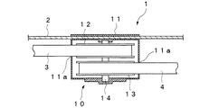
ロープ巻取器10は、巻取器本体11内に計2つの第1及び第2のリール12,13を備え、第1のリール12には第1のロープ3が巻き取られ、第2のリール13には第2のロープ4が巻き取られるようになっている。各リール12,13は互いに巻取器本体11の前後方向に配置され、共通の回転軸14に同軸状に取付けられている。巻取器本体11には各ロープ3,4を挿通する孔11aが幅方向一方の側面及び他方の側面にそれぞれ設けられ、第1のロープ3は巻取器本体11の左側に引き出され、第2のロープ4は巻取器本体11の右側に引き出されるようになっている。各リール12,13は図示しないスプリングによってそれぞれ巻き取り方向に付勢され、第1のロープ3または第2のロープ4を巻取器本体11から引き出すと、図示しないストッパ機構によってロープ3,4が任意の引き出し位置で保持されるようになっている。巻取器本体11の下面には計2つの操作部11b,11cが設けられ、一方の操作部11bを押圧操作すると、前記ストッパ機構が解除されて第1のリール12が前記スプリングによって巻き取り方向に回転し、第1のロープ3が第1のリール12に巻き取られるようになっている。また、他方の操作部11cを押圧操作すると、前述と同様に第2のロープ4が第2のリール13に巻き取られるようになっている。
【0018】
前記安全帯1は、第1のロープ3のフック5または第2のロープ4のフック6を作業現場の親綱等に掛けることによって使用され、作業者が作業場所を移動する際、例えば第1のロープ3が親綱に連結されている場合は、第1のロープ3のフック5を親綱に繋止させたまま第2のロープ4のフック6を親綱に掛けた後、第1のロープ3のフック5を親綱から外すことにより、常に何れか一方のロープ3,4を親綱に繋止させておくことができる。また、例えば第1のロープ3を親綱に連結している際、使用していない方の第2のロープ4をロープ巻取器10に巻き取っておくことにより、第2のロープ4が安全帯1からループ状に垂れ下がることがなく、垂れ下がったロープが周囲の突起物等に接触して作業や移動の妨げになったり、或いはロープが床面等との接触によって摩耗してロープの強度が低下するといった不具合を生ずることがない。
【0019】
本実施形態のロープ巻取器10では、各ロープ3,4をそれぞれ巻き取り可能な計2つのリール12,13を巻取器本体11に一体に備えているので、安全帯1の胴ベルト2に計2個のロープ巻取器を取付けた場合に比べ、幅方向の取付スペースを大幅に少なくすることができる。従って、工具等の他の装備品を胴ベルト2に装着するためのスペースを十分に確保することができる。
【0020】
この場合、各リール12,13を巻取器本体11の前後方向に配置して互いに同軸状に設けたので、巻取器本体11が幅方向に大型化することがなく、幅方向の取付スペースをより一層小さくすることができる。
【0021】
また、各リール12,13のロープ3,4をそれぞれ巻取器本体11の左右方向に引き出し可能に構成したので、作業者が各ロープ3,4のフック5,6をそれぞれ両手で操作することができ、例えば左手で第1のロープ3のフック5を親綱に掛けて、右手で第2のロープ4のフック6を外すなど、ロープの掛け替え作業を極めて容易に行うことができる。
【0022】
尚、前記実施形態では、各ロープ3,4をそれぞれ巻取器本体11の左右方向に引き出し可能に構成したものを示したが、同一方向に引き出すように構成したものであってもよい。
【0023】
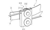
図4及び図5は本発明の他の実施形態を示すもので、図4はロープ巻取器の斜視図、図5はその正面断面図である。尚、前記実施形態と同等の構成部分には同一の符号を付して示す。
【0024】
本実施形態のロープ巻取器20は、巻取器本体21内に計2つの第1及び第2のリール22,23を備え、第1のリール22には第1のロープ3が巻き取られ、第2のリール23には第2のロープ4が巻き取られるようになっている。各リール22,23は互いに巻取器本体21の上下方向に配置され、計2つの回転軸24,25にそれぞれ取付けられている。巻取器本体21には各ロープ3,4を挿通する孔21aが幅方向一方の側面及び他方の側面にそれぞれ設けられ、第1のロープ3は巻取器本体21の左側に引き出され、第2のロープ4は巻取器本体21の右側に引き出されるようになっている。また、各リール22,23は図示しないスプリングによってそれぞれ巻き取り方向に付勢されている。
【0025】
本実施形態のロープ巻取器20では、前記実施形態と同様、各ロープ3,4をそれぞれ巻き取り可能な計2つのリール22,23を巻取器本体21に一体に備えているので、安全帯1の胴ベルト2に計2個のロープ巻取器を取付けた場合に比べ、幅方向の取付スペースを大幅に少なくすることができる。
【0026】
この場合、各リール22,23を巻取器本体21の上下方向に配置したので、巻取器本体21が幅方向に大型化することがなく、幅方向の取付スペースをより一層小さくすることができる。
【0027】
尚、前記実施形態では、各リール22,23を互いに巻取器本体21の上下方向に配置したものを示したが、巻取器本体21の左右方向に配置するようにしてもよい。
【0028】
【発明の効果】
以上説明したように、請求項1の安全帯のロープ巻取器によれば、計2本のロープを備えた安全帯に用いる場合でも、他の装備品等を安全帯のベルトに装着するためのスペースを十分に確保することができるので、作業性を損なうことがないという利点がある。
【0029】
また、請求項2または3の安全帯のロープ巻取器によれば、請求項1の効果に加え、巻取器本体が幅方向に大型化することがないので、幅方向の取付スペースをより一層小さくすることができる。
【0030】
また、請求項4の安全帯のロープ巻取器によれば、請求項1、2または3の効果に加え、作業者が各ロープのフックをそれぞれ両手で操作することができるので、ロープの掛け替え作業を極めて容易に行うことができる。
【図面の簡単な説明】
【図1】本発明の一実施形態を示すロープ巻取器を備えた安全帯の全体図
【図2】ロープ巻取器の斜視図
【図3】ロープ巻取器の平面断面図
【図4】本発明の他の実施形態を示すロープ巻取器の斜視図
【図5】ロープ巻取器の正面断面図
【符号の説明】
1…安全帯、3…第1のロープ、4…第2のロープ、5,6…フック、10…ロープ巻取器、11…巻取器本体、12…第1のリール、13…第2のリール、12…ロープ巻取器、21…巻取器本体、22…第1のリール、23…第2のリール。[0001]
TECHNICAL FIELD OF THE INVENTION
TECHNICAL FIELD The present invention relates to a safety band rope winder used by an operator in high-place work such as a construction site.
[0002]
[Prior art]
Generally, when working at a high place such as a construction site, workers are required to wear a safety belt to prevent falls. This safety belt has a rope of a predetermined length, and a hanging hook attached to the tip of the rope is hung on a master rope or the like at the work site so that the worker can be supported by the rope in case of a fall. I have to.
[0003]
By the way, at a construction site, when an operator moves from one work place to another, the safety belt rope hook must be temporarily removed from the main rope, and the hook must be hooked on the main rope again at the destination work place. Even during the changeover, the hook is detached from the parent rope even temporarily, so the safety against fall prevention is not perfect. Therefore, for example, as described in
[0004]
[Patent Document 1]
Japanese Utility Model Publication No. 7-33360 [Patent Document 2]
JP-A-8-89592 [0005]
[Problems to be solved by the invention]
However, in the above-mentioned conventional example, since each rope of a predetermined length is connected to the belt of the safety belt, the unused rope hangs down in a loop, and the hanging rope comes into contact with surrounding protrusions and the like. In addition, there is a problem in that work or movement is hindered, or the rope is worn by contact with a floor surface or the like, and the strength of the rope is reduced.
[0006]
Thus, for example, by using a total of two rope winders as described in
[0007]
The present invention has been made in view of the above problems, and a purpose thereof is to attach other equipments and the like to a safety belt even when the safety belt is used with a total of two ropes. An object of the present invention is to provide a safety belt rope winder that does not impair space.
[0008]
[Means for Solving the Problems]
In order to achieve the above object, according to the present invention, in the rope retractor for a safety belt provided with a total of two ropes each having a locking hook at a tip thereof, each of the ropes can be wound. The reel unit is provided with a total of two reels. Thereby, since a total of two reels are provided in the winder main body, the mounting space is reduced as compared with a case where a total of two rope winders are mounted on the safety belt.
[0009]
According to a second aspect of the present invention, in the rope take-up device for a safety belt according to the first aspect, the respective reels are arranged coaxially with each other. Thus, in addition to the function of the first aspect, since the reels are arranged coaxially with each other, the winder main body does not become large in the width direction.
[0010]
According to a third aspect of the present invention, in the rope take-up device for a safety belt according to the first aspect, the respective reels are vertically arranged with respect to each other. Thus, in addition to the function of the first aspect, since the reels are arranged vertically with respect to each other, the winder main body does not become large in the width direction.
[0011]
The rope retractor for a safety belt according to
[0012]
According to a fourth aspect of the present invention, in the rope take-up device of the safety belt according to the first, second, or third aspect, the rope of each of the reels is configured to be able to be pulled out in the left-right direction of the take-up device body. This allows the operator to operate the hooks of each rope with both hands in addition to the effects of the first, second, or third aspect.
[0013]
BEST MODE FOR CARRYING OUT THE INVENTION
1 to 3 show an embodiment of the present invention. FIG. 1 is an overall view of a safety belt provided with a rope winder of the present invention, FIG. 2 is a perspective view of the rope winder, and FIG. It is the plane sectional view.
[0014]
The
[0015]
The
[0016]
Each of the
[0017]
The
[0018]
The
[0019]
In the
[0020]
In this case, since the reels 12 and 13 are arranged in the front-rear direction of the winder
[0021]
In addition, since the
[0022]
In the above-described embodiment, the
[0023]
4 and 5 show another embodiment of the present invention. FIG. 4 is a perspective view of a rope winder, and FIG. 5 is a front sectional view thereof. The same components as those in the above embodiment are denoted by the same reference numerals.
[0024]
The
[0025]
In the
[0026]
In this case, since the
[0027]
In the above-described embodiment, the
[0028]
【The invention's effect】
As described above, according to the rope retractor of the safety belt according to the first aspect, even when used in a safety belt having a total of two ropes, other equipment and the like can be mounted on the belt of the safety belt. Is sufficient, and there is an advantage that workability is not impaired.
[0029]
Further, according to the rope retractor of the safety belt of the second or third aspect, in addition to the effect of the first aspect, the main body of the retractor does not become large in the width direction. It can be even smaller.
[0030]
According to the safety belt rope winder of
[Brief description of the drawings]
FIG. 1 is an overall view of a safety belt provided with a rope winder according to an embodiment of the present invention. FIG. 2 is a perspective view of the rope winder. FIG. 3 is a plan sectional view of the rope winder. FIG. 5 is a perspective view of a rope winder showing another embodiment of the present invention. FIG. 5 is a front sectional view of the rope winder.
DESCRIPTION OF
Claims (4)
前記各ロープをそれぞれ巻き取り可能な計2つのリールを巻取器本体に備えたことを特徴とする安全帯のロープ巻取器。In a rope retractor of a safety belt provided with a total of two ropes having a locking hook at a tip thereof,
A rope take-up device for a safety belt, wherein a total of two reels capable of taking up each of the ropes are provided in a take-up device main body.
Priority Applications (1)
| Application Number | Priority Date | Filing Date | Title |
|---|---|---|---|
| JP2003095312A JP2004249062A (en) | 2002-12-27 | 2003-03-31 | Rope winder for safety belt |
Applications Claiming Priority (2)
| Application Number | Priority Date | Filing Date | Title |
|---|---|---|---|
| JP2002379127 | 2002-12-27 | ||
| JP2003095312A JP2004249062A (en) | 2002-12-27 | 2003-03-31 | Rope winder for safety belt |
Publications (1)
| Publication Number | Publication Date |
|---|---|
| JP2004249062A true JP2004249062A (en) | 2004-09-09 |
Family
ID=33031823
Family Applications (1)
| Application Number | Title | Priority Date | Filing Date |
|---|---|---|---|
| JP2003095312A Pending JP2004249062A (en) | 2002-12-27 | 2003-03-31 | Rope winder for safety belt |
Country Status (1)
| Country | Link |
|---|---|
| JP (1) | JP2004249062A (en) |
Cited By (9)
| Publication number | Priority date | Publication date | Assignee | Title |
|---|---|---|---|---|
| GB2449134A (en) * | 2007-08-13 | 2008-11-12 | Checkmate Safety Llp | Fall Arrest Block |
| JP2011512906A (en) * | 2008-02-25 | 2011-04-28 | スペリアン フォール プロテクション インコーポレイテッド | System for use with multiple safety devices and connector for use therewith |
| WO2012043989A3 (en) * | 2010-09-27 | 2012-05-24 | 엘지전자 주식회사 | Method for partitioning block and decoding device |
| JP2016195763A (en) * | 2015-04-03 | 2016-11-24 | イヴェコ・マギルス・アー・ゲーIveco Magirus Ag | Fall protection device |
| JP2017205153A (en) * | 2016-05-16 | 2017-11-24 | 中部建材株式会社 | Fall prevention device |
| KR101871140B1 (en) * | 2018-01-25 | 2018-07-20 | 양모 | Multipurpose belt |
| KR20190088631A (en) * | 2018-01-19 | 2019-07-29 | 최명수 | Wire device for hanging lifeline to scaffolding |
| JP2020044157A (en) * | 2018-09-20 | 2020-03-26 | サンコー株式会社 | Winding device for safety belt and fall stop device using the same |
| KR102450609B1 (en) * | 2022-03-03 | 2022-10-06 | 주식회사 후스 | Assistance apparatus for working using a spring balance |
-
2003
- 2003-03-31 JP JP2003095312A patent/JP2004249062A/en active Pending
Cited By (17)
| Publication number | Priority date | Publication date | Assignee | Title |
|---|---|---|---|---|
| US8991556B2 (en) | 2007-08-13 | 2015-03-31 | Checkmate Limited | Fall arrest block |
| GB2449134B (en) * | 2007-08-13 | 2009-08-12 | Checkmate Safety Llp | Fall arrest block |
| GB2449134A (en) * | 2007-08-13 | 2008-11-12 | Checkmate Safety Llp | Fall Arrest Block |
| JP2011512906A (en) * | 2008-02-25 | 2011-04-28 | スペリアン フォール プロテクション インコーポレイテッド | System for use with multiple safety devices and connector for use therewith |
| US10863196B2 (en) | 2010-09-27 | 2020-12-08 | Lg Electronics Inc. | Method for partitioning block and decoding device |
| WO2012043989A3 (en) * | 2010-09-27 | 2012-05-24 | 엘지전자 주식회사 | Method for partitioning block and decoding device |
| US11375233B2 (en) | 2010-09-27 | 2022-06-28 | Lg Electronics Inc. | Method for partitioning block and decoding device |
| US11895333B2 (en) | 2010-09-27 | 2024-02-06 | Lg Electronics Inc. | Method for partitioning block and decoding device |
| JP2016195763A (en) * | 2015-04-03 | 2016-11-24 | イヴェコ・マギルス・アー・ゲーIveco Magirus Ag | Fall protection device |
| JP2017205153A (en) * | 2016-05-16 | 2017-11-24 | 中部建材株式会社 | Fall prevention device |
| KR20190088631A (en) * | 2018-01-19 | 2019-07-29 | 최명수 | Wire device for hanging lifeline to scaffolding |
| KR102023404B1 (en) * | 2018-01-19 | 2019-09-20 | 최명수 | Wire device for hanging lifeline to scaffolding |
| KR101871140B1 (en) * | 2018-01-25 | 2018-07-20 | 양모 | Multipurpose belt |
| WO2019146873A1 (en) * | 2018-01-25 | 2019-08-01 | 손수희 | Multipurpose belt |
| JP2020044157A (en) * | 2018-09-20 | 2020-03-26 | サンコー株式会社 | Winding device for safety belt and fall stop device using the same |
| JP7114068B2 (en) | 2018-09-20 | 2022-08-08 | サンコー株式会社 | Winder for safety belt and fall arrest device using the same |
| KR102450609B1 (en) * | 2022-03-03 | 2022-10-06 | 주식회사 후스 | Assistance apparatus for working using a spring balance |
Similar Documents
| Publication | Publication Date | Title |
|---|---|---|
| US20130008933A1 (en) | Tool belt with integrated tool retraction mechanism | |
| JP2004249062A (en) | Rope winder for safety belt | |
| JP2007153583A (en) | Hook device | |
| JP6423180B2 (en) | High altitude worker fall prevention system and roll-up type fall prevention equipment | |
| GB2431631A (en) | Invalid hoist | |
| JP6027833B2 (en) | Harness-type safety belt with strap-operated unlocking winder | |
| JP6481065B2 (en) | Wheelchair fixing device | |
| JP5872915B2 (en) | Lanyard holder | |
| JP2014210008A (en) | Lanyard, and safety belt with the same | |
| JP3158511U (en) | Tape measure | |
| JP2008202395A (en) | Seat for construction installation | |
| KR200467556Y1 (en) | Apparatus binding stowage for truck | |
| JP2014155652A (en) | Wheelchair fixing device | |
| KR20130062679A (en) | Spare tire carrier | |
| JP6683317B2 (en) | Fall prevention device | |
| KR102311883B1 (en) | Bicycle anti-theft device using bicycle saddie | |
| JPH08215326A (en) | Fall preventing device | |
| JP5030736B2 (en) | Winding unit | |
| JP6805859B2 (en) | Jib mooring device mounting structure | |
| JP3499329B2 (en) | Safety belt for order picking vehicles | |
| JP2011188899A (en) | Fall prevention apparatus | |
| JP3145096U (en) | Safety belt strap winder for crash prevention | |
| JP7278243B2 (en) | fall arrest equipment | |
| JP2964477B1 (en) | Load collapse prevention device for forklift | |
| JP3916434B2 (en) | Locking device of fixing device |
Legal Events
| Date | Code | Title | Description |
|---|---|---|---|
| A621 | Written request for application examination |
Effective date: 20060324 Free format text: JAPANESE INTERMEDIATE CODE: A621 |
|
| A977 | Report on retrieval |
Effective date: 20090128 Free format text: JAPANESE INTERMEDIATE CODE: A971007 |
|
| A131 | Notification of reasons for refusal |
Effective date: 20090206 Free format text: JAPANESE INTERMEDIATE CODE: A131 |
|
| A521 | Written amendment |
Effective date: 20090402 Free format text: JAPANESE INTERMEDIATE CODE: A523 |
|
| A02 | Decision of refusal |
Effective date: 20090423 Free format text: JAPANESE INTERMEDIATE CODE: A02 |