JP2004248897A - Vacuum cleaner - Google Patents
Vacuum cleaner Download PDFInfo
- Publication number
- JP2004248897A JP2004248897A JP2003042832A JP2003042832A JP2004248897A JP 2004248897 A JP2004248897 A JP 2004248897A JP 2003042832 A JP2003042832 A JP 2003042832A JP 2003042832 A JP2003042832 A JP 2003042832A JP 2004248897 A JP2004248897 A JP 2004248897A
- Authority
- JP
- Japan
- Prior art keywords
- exhaust
- vacuum cleaner
- lid
- electric blower
- attachment
- Prior art date
- Legal status (The legal status is an assumption and is not a legal conclusion. Google has not performed a legal analysis and makes no representation as to the accuracy of the status listed.)
- Granted
Links
Images


Abstract
Description
【0001】
【発明の属する技術分野】
本発明は、排気をブロアーとして利用できる一般家庭で使用される電気掃除機に関するものである。
【0002】
【従来の技術】
従来のこの種の電気掃除機を、図14、図15を用いて説明する。
【0003】
図14、図15において、掃除機本体1の前方には、集塵用ホース(図示せず)を着脱自在に接続する吸気口2と、この吸気口2に連通する集塵室4が設けられている。
【0004】
掃除機本体1の後方には、塵埃を吸引するための吸引風を発する電動送風機5が配設され、掃除機本体1の後面には、第二排気部6と、第一排気部7が設けられており、前記第二排気部6には、前記第二排気部6を開閉する蓋体8が設けられている。この蓋体8はバネ体9によって第二排気部6を閉塞される方向に付勢されている。また、この第二排気部6は、掃除機本体1の長手方向で被掃除面とほぼ水平に形成されている。
【0005】
上記のように、通常は、第二排気部6が蓋体8により閉塞されており、図14の示すように、矢印Aのように排気風は、第一排気部7から放出される。また、ブロアーとして使用する際は、図15に示すように、ホース接続管10を前記第二排気部6に接続することにより、矢印Bのように排気風は、ホース接続管10内を通り排気を放出されていた(例えば、特許文献1参照)。
【0006】
【特許文献1】
特開昭61−50535号公報(第1−4頁、第1図)
【0007】
【発明が解決しようとする課題】
しかしながら上記従来の掃除機本体1では、第二排気部6は掃除機本体1の長手方向で被掃除面とほぼ水平に形成されていることより、使用者が、ブロアーとして、ホース接続管10を第二排気部6に接続する際、ホース接続管10は、第二排気部6に対してほぼ垂直にしなければならないことより、大きく屈んでホース接続管10を第二排気部6に接続するため、身体や手首に負担がかかり手間がかかるという問題点もあった。
【0008】
また、通常の使用状態で第二排気部6が蓋体8により閉塞されている時、第二排気部6と蓋体8との間のわずかな隙間から排気風が洩れて、被掃除面のゴミや近傍の書類などの吹き上げる問題もあった。
【0009】
本発明は、上記課題を解決するもので、ブロアー部品を排気部に接続する時の動作を容易にすることで、使用者への負担を低減するとともに、排気部から洩れる排気風が、被掃除面のゴミを吹飛ばすことを防止することで、使用性を向上させた電気掃除機を提供することを目的とする。
【0010】
【課題を解決するための手段】
上記従来の課題を解決するために本発明は、吸引風を発する電動送風機と、前記電動送風機の排気側と連通する第一排気部と第二排気部とを備え、前記第二排気部にはアタッチメントおよび/またはアタッチメントに接続された接続部が接続可能であるとともに、前記開口を上方向に傾斜させた傾斜面にて形成したもので、ブロアーとして、アタッチメントや接続部を第二排気部に接続する際、前記第二排気部の開口は被掃除面に対して上方に傾いているため、使用者は第二排気部に対して鈍角にアタッチメントや接続部をもって第二排気部に接続できることで、手首にかかる負担を軽減させ、かつ、第二排気部からわずかに洩れる排気風は、被掃除面に対して上方に放出されるので被掃除面のゴミや、近傍の書類などの吹き上がりを廉価な構成で低減させることができる。
【0011】
【発明の実施の形態】
本発明の請求項1記載の発明は、吸引風を発する電動送風機と、前記電動送風機の排気側と連通する第一排気部と第二排気部とを備え、前記第二排気部にはアタッチメントおよび/またはアタッチメントに接続された接続部が接続可能であるとともに、前記開口を上方向に傾斜させた傾斜面にて形成したもので、ブロアーとして、アタッチメントや接続部を第二排気部に接続する際、前記第二排気部の開口は被掃除面に対して上方に傾いているため、使用者は第二排気部に対して鈍角にアタッチメントや接続部をもって第二排気部に接続できることで、手首にかかる負担を軽減させ、かつ、第二排気部からわずかに洩れる排気風は、被掃除面に対して上方に放出されるので被掃除面のゴミや、近傍の書類などの吹き上がりを廉価な構成で低減させることができる。
【0012】
また、結果的に、ブロアーを高い所で清掃する時、接続部であるホースが鋭角に屈曲することが少なくなり、ホース内の吸気通路の圧損を損なわせること無く性能低下を防止する。
【0013】
本発明の請求項2記載の発明は、傾斜面の外周に、上方向に傾斜させた凸部を設けたもので、ブロアーとして、アタッチメントや接続部を第二排気部に接続する際、上方向に傾斜させた凸部が、アタッチメントや接続部のさそいとなることで着脱が容易となり、かつ廉価な構成で、開口から漏れる排気風で被掃除面のゴミの吹飛ばしを抑制することができる。
【0014】
本発明の請求項3記載の発明は、第二排気部に対して開閉自在の蓋体を備え、前記蓋体の大気側に凸部を設けたもので、ブロアーとして、アタッチメントや接続部を第二排気部に接続する際、アタッチメントや接続部の内径が、凸部によってさそいとなることで、確実に着脱でき使い勝手が向上する。
【0015】
本発明の請求項4記載の発明は、開口と蓋体との間に軟質材を設けたもので、第二排気部の開口と蓋体との間からわずかに排出される排気風の流出を防止でき、被掃除面のゴミの吹飛ばし抑制させることができる。
【0016】
本発明の請求項5記載の発明は、電動送風機の排気側と第二排気部との間に、塵埃捕集手段を設けたもので、電動送風機からの微細な塵埃は、塵埃捕集手段で捕集され、ブロアーとして使っても、ブロアーからの排気風は清潔になり排気の洗浄度を向上させる。
【0017】
本発明の請求項6記載の発明は、蓋体に電動送風機の排気側と連通する連通部を設けたもので、熱のこもりやすい電動送風機からの排気風を外気に放出し、電動送風機の過熱を抑制することで、電動送風機の冷却効果と耐久性を向上させることができる。
【0018】
本発明の請求項7記載の発明は、第二排気部の近傍に、前記第二排気部に接続可能なアタッチメントを収納したもので、第二排気部にアタッチメントを接続するとき手間がかからず、使用性が向上する。
【0019】
本発明の請求項8記載の発明は、第二排気部に接続可能なアタッチメントを、掃除機本体の長手方向の中心軸に対して水平方向に略直角に配置したもので、掃除機本体の長手方向の全長を短くでき、ひいては掃除機本体の小型化が寄与できる。
【0020】
【実施例】
(実施例1)
以下、本発明の第1の実施例について、図1〜図9を用いて説明する。
【0021】
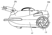
図1は、本発明の第1の実施例を示す掃除機本体の上面図であり、図2は、その掃除機本体の側面図であり、図3は掃除機本体の背面図である。図4は掃除機本体の側面断面図であり、図5は掃除機本体の上方断面図である。図6は、蓋体を示す部分側面断面図であり、図7は、蓋体を示す部分上方断面図である。図8は、ホース接続管を蓋体に挿入する時の動作図で、図9は、ホース接続管を蓋体に挿入した時の部分構想図である。
【0022】
図4において、掃除機本体11の後方には、塵埃を吸引するための吸引風を発する電動送風機12を内蔵した電動送風機室13、掃除機本体11の前方には、前記電動送風機12の吸気側に連通し、塵埃を捕集する略円形状の集塵室14が設けられている。また、集塵室14は掃除機本体11と着脱自在に構成されている。掃除機本体11の前方下面には、走行手段である移動用キャスター15が枢支されており、掃除機本体11の後方両側面には、一対の移動用車輪16が回転自在に備えられている。
【0023】
集塵室14内には、微細な塵埃捕集用のメインフィルター17とメインフィルター17に回転自在に取付けられた、粗い塵埃を捕集するための略円錐形状でメッシュ部18を有するプレフィルター19が設けられている。また、集塵室14の上部前方には、吸気口20が備えられている。集塵室14に連通し、塵埃を吸引するアタッチメント(図示せず)を接続した接続部であるホース21の一端には、ホース接続管22が設けられており、このホース接続管22は、吸気口20と着脱、及び、回動自在に取付けられている。
【0024】
図5、図7において、掃除機本体11の後方には、電動送風機12から放出される排気を外部に放出する第一排気部23が形成されており、また、集中排気を利用する時に、前記接続部であるホース21の一端のホース接続管22が挿入接続できる第二排気部24が形成されている。
【0025】
第二排気部24には、この第二排気部24を回動自在に開閉する蓋体25が配設されており、蓋体25の回動軸26にはバネ27が付勢されており、このバネ27によってこの蓋体25が、第二排気部24を常時閉塞するように設けられている。図7において、電動送風機12から放出される排気は、掃除機本体11に形成されている仕切りリブ28で形成された排気経路29を通り矢印方向へと連通する。
【0026】
図9において、集中排気を利用するブロアーとして使用する際で、ホース接続管22を第二排気部24に挿入接続すると、蓋体25は、ホース接続管22に押され、矢印A方向に回動する。この時、蓋体25は、仕切りリブ28に当たり、通常の電動送風機12から排気を、蓋体25によって遮断し、矢印Bで示すように排気風はホース接続管22内を通り排気を放出するようになっている。
【0027】
また、図8において、第二排気部24の開口部30は、前記走行手段を被掃除面に接地させた通常掃除状態において、被掃除面に対して上方向に傾斜させた傾斜面31にて形成されている。
【0028】
上記構成において動作、作用を説明する。
【0029】
図8において、第二排気部24の開口部30に傾斜面31を設けることより、第二排気部24の開口部30から漏れる排気は、被掃除面に対して上方に排出されることとなり、被掃除面のゴミや近傍の書類などを吹飛ばすことを低減させる。
【0030】
また、ブロアーとして、ホース接続管22を第二排気部24に挿入する際、ホース接続管22は上方向から下方向へと斜めに挿入して行くため、使用者は第二排気部24が見易くなり、使用者にとって鈍角な方向でホース接続管22をもって第二排気部24に接続することができ大きく屈むことなく手首の負担を軽減させる。
【0031】
また、結果的に、ブロアー効果を高い所で使用する時、ホース接続管22と接続されているホース21が鋭角に屈曲することがなくなり、ホース21内の吸気通路の圧損を損なわせること無く性能低下を防止する。
【0032】
また、図3、図6及び、図8において、第二排気部24の開口部30の外周で、この開口部30の下方で略半分、掃除機本体11の被掃除面に対して上方に傾斜させた凸部なる傾斜リブ32が形成されている。このことより、使用者がブロアーとして、ホース接続管22を第二排気部24に挿入する際、傾斜リブ32がホース接続管22をさそいホース接続管22の挿入が容易となり、かつ廉価な構成で、開口部30から若干漏れる排気風で被掃除面のゴミ吹飛ばしを防止する。
【0033】
また、第二排気部24の開口部30を回動自在に開閉す蓋体25の外気側に略円錐状の凸部なる突起リブ33が設けられている。このことより、使用者がブロアーとして、ホース接続管22を第二排気部24に挿入する際、使用者は第二排気部24に形成された蓋体25が見易くなり、かつ、ホース接続管22の内径が、突起リブ33によってさそわれホース接続管22の着脱が容易となり使い勝手が向上する。
【0034】
図6、図7において、第二排気部24の開口部30と、蓋体25との間に、軟質材なるエアータイト用のパッキン体34が接着等により係止されている。このことより、第二排気部24の開口部30と、蓋体25とに生じる部品形状のバラツキで、第二排気部24の開口部30と、蓋体25との間からわずかに排出される排気風の流出を防止できる。
【0035】
図7、図9において電動送風機12を内蔵した電動送風機室13から排気が流れる排気経路29で、電動送風機室13と第二排気部24との間に粗い塵埃を捕集する塵埃捕集手段であるフィルター35が配設されている。このフィルター35は、掃除機本体11に形成されたガイドリブ36で係止されている。このことより、図9のように、ブロアーとして、ホース接続管22を第二排気部24に接続して使っても、電動送風機12からの放出される微細な塵埃はフィルター35で捕集され、ブロアーからの排気風は清潔になり排気の洗浄度を向上させる。
【0036】
図3、図6において、第二排気部24の開口部30を回動自在に開閉す蓋体25の外気側に複数個の連通部なる穴37が設けられている。このことより、熱がこもりやすい電動送風機室13からの排気圧を和らげ、排気風を外気に逃がし、電動送風機12の過熱を抑制する。結果的に電動送風機12の冷却効果と耐久性を向上させることができる。
【0037】
なお、本実施例においては、塵埃を吸引するアタッチメント(図示せず)を接続した接続部であるホース21の一端に形成されたホース接続管22を、第二排気部24に挿入接続する場合について述べたが、第二排気部24に直接挿入接続可能なアタッチメント(図示せず)を用いても同様の効果は得られる。
【0038】
(実施例2)
以下、本発明の第2の実施例について、図10〜図13を用いて説明する。
【0039】
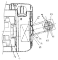
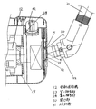
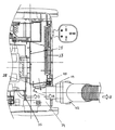
図10は本発明の実施例2の掃除機本体の後方要部断面図である。図11はその掃除機本体の格納蓋を開閉した時の動作図。図12は、アタッチメント及び、集塵フィルターを取外した時の動作図である。図13は、掃除機本体の一部切り欠いた平面図である。本実施例2は、実施例1からアタッチメントの収納に関して詳細に表したものである。なお、実施例1と同符号のものは同一構造を有し、その説明は省略する。
【0040】
図7、図10、及び、図11において、電動送風機室13からの排気が流れる排気経路29に設けられた第一排気部23の後方には、細塵捕集用の集塵フィルター38が配設されており、この集塵フィルター38には突起部39を有した引掛け40が設けられており、この引掛け40は、掃除機本体11に形成された凹み部41と嵌合し着脱自在に形成されている。
【0041】
また、細塵捕集用の集塵フィルター38と、排気経路29を形成する仕切りリブ28との間に、少なくとも1つが第二排気部24に直接接続可能な複数個のアタッチメント42が、掃除機本体11に形成された収納部43に収納されている。
【0042】
集塵フィルター38と前記複数個のアタッチメント42の上部には、格納蓋44が設けられており、この格納蓋44は、掃除機本体11の回動軸45を中心にして回動自在に構成されている。この格納蓋44を回動させることより、集塵フィルター38と前記複数個のアタッチメント42は、図12の矢印方向に取外せる様になっている。このことより、格納蓋44で、複数個のアタッチメント42及び、集塵フィルター38を覆うことから、複数個のアタッチメント42及び集塵フィルター38は隠され簡単な構成で掃除機本体11の外観美を損なうことがなくなる。また、第二排気部24に直接接続可能なアタッチメント42を接続するとき手間がかからず、使用性が向上する。
【0043】
図10、図13において、細塵捕集用の集塵フィルター38と、複数個のアタッチメント42は、掃除機本体11の長手方向の中心軸に対して水平方向46に略直角で縦列配置されている。このことより、図10で示す掃除機本体11の長手寸法Lを短くでき、ひいては掃除機本体11の無駄な空間がなくなりコンパクト化が可能となる。
【0044】
また、図10、図11において、格納蓋44は、掃除機本体11の回動軸45を中心にして回動自在に構成されているとともに、格納蓋44の引掛け部47は、着脱自在の細塵捕集用の集塵フィルター38に形成されたコ字状の保持部48で、嵌合し、着脱自在に係止されている。このことより、大きな部品である掃除機本体11側に複雑な金型構成で、保持部48を形成させることがなくなる。
【0045】
また、金型的に比較的小さい部品である集塵フィルター38に保持部48を形成することより金型費も少なくてすみ廉価な構成で集塵フィルター38の保持部48が形成できる。
【0046】
【発明の効果】
以上説明したように本発明よれば、ブロアー部品を排気部に接続する時の動作を容易にすることで、使用者への負担を低減するとともに、排気部から洩れる排気風が、被掃除面のゴミを吹飛ばすことを防止することで、使用性を向上させた電気掃除機を提供できる。
【図面の簡単な説明】
【図1】本発明の第1の実施例における掃除機本体の上面図
【図2】同掃除機本体の側面図
【図3】同掃除機本体の背面図
【図4】同掃除機本体の側断面図
【図5】同電気掃除機の上方断面図
【図6】同掃除機本体の蓋体を示す部分側面断面図
【図7】同掃除機本体の蓋体を示す部分平面断面図
【図8】同掃除機本体のホース接続管を蓋体に挿入する時の動作図
【図9】同掃除機本体のホース接続管を蓋体に挿入した時の部分構想図
【図10】本発明の第2の実施例における掃除機本体の後方要部断面図
【図11】同掃除機本体の格納蓋を開閉した時の動作図
【図12】同掃除機本体のアタッチメント及び集塵フィルターを取外した時の動作図
【図13】同掃除機本体の一部切り欠いた平面図
【図14】従来の電気掃除機の側断面図
【図15】同ホース接続管を蓋体に挿入した時の部分構想図
【符号の説明】
11 掃除機本体
12 電動送風機
14 集塵室
22 ホース接続管
23 第一排気部
24 第二排気部
25 蓋体
30 開口部
31 傾斜面[0001]
TECHNICAL FIELD OF THE INVENTION
TECHNICAL FIELD The present invention relates to a vacuum cleaner used in ordinary households where exhaust gas can be used as a blower.
[0002]
[Prior art]
A conventional vacuum cleaner of this type will be described with reference to FIGS.
[0003]
In FIGS. 14 and 15, in front of the cleaner body 1, an
[0004]
An electric blower 5 that generates a suction wind for sucking dust is provided behind the cleaner body 1, and a
[0005]
As described above, the
[0006]
[Patent Document 1]
JP-A-61-50535 (pages 1-4, FIG. 1)
[0007]
[Problems to be solved by the invention]
However, in the above-mentioned conventional cleaner body 1, the
[0008]
Further, when the
[0009]
SUMMARY OF THE INVENTION The present invention solves the above-described problems, and reduces the burden on a user by facilitating an operation when connecting a blower component to an exhaust unit, and also reduces exhaust air leaking from the exhaust unit to be cleaned. An object of the present invention is to provide a vacuum cleaner having improved usability by preventing dust from being blown off on a surface.
[0010]
[Means for Solving the Problems]
In order to solve the above conventional problems, the present invention includes an electric blower that emits suction air, a first exhaust unit and a second exhaust unit that communicate with the exhaust side of the electric blower, and the second exhaust unit includes An attachment and / or a connection part connected to the attachment can be connected, and the opening is formed by an inclined surface inclined upward, and the attachment or the connection part is connected to the second exhaust part as a blower. In doing so, the opening of the second exhaust portion is inclined upward with respect to the surface to be cleaned, so that the user can connect to the second exhaust portion with an attachment or connection portion at an obtuse angle to the second exhaust portion, The exhaust air that reduces the burden on the wrist and that leaks slightly from the second exhaust unit is released upward to the surface to be cleaned, making it possible to reduce the amount of dust on the surface to be cleaned and blow-up of nearby documents. What It can be reduced by forming.
[0011]
BEST MODE FOR CARRYING OUT THE INVENTION
The invention according to claim 1 of the present invention includes an electric blower that generates a suction wind, a first exhaust unit and a second exhaust unit that communicate with the exhaust side of the electric blower, and an attachment and a second exhaust unit. And / or the connection part connected to the attachment is connectable, and the opening is formed by an inclined surface which is inclined upward. When the attachment or the connection part is connected to the second exhaust part as a blower. Since the opening of the second exhaust portion is inclined upward with respect to the surface to be cleaned, the user can connect to the second exhaust portion with an attachment or a connecting portion at an obtuse angle with respect to the second exhaust portion, so that the user can attach to the wrist. This structure reduces the burden, and the exhaust air that leaks slightly from the second exhaust unit is discharged upward to the surface to be cleaned, so that the dust on the surface to be cleaned and the blow-up of nearby documents can be reduced. Reduced by It can be.
[0012]
Further, as a result, when the blower is cleaned at a high place, the hose serving as the connecting portion is less bent at an acute angle, and the performance is prevented from deteriorating without impairing the pressure loss of the intake passage in the hose.
[0013]
The invention according to
[0014]
The invention according to claim 3 of the present invention includes a lid that is openable and closable with respect to the second exhaust portion, and a convex portion is provided on the atmosphere side of the lid, and an attachment or a connection portion is used as a blower. When connecting to the second exhaust portion, the inner diameter of the attachment or the connection portion is determined by the convex portion, so that it can be securely attached and detached and the usability is improved.
[0015]
The invention according to claim 4 of the present invention provides a soft material between the opening and the lid, and suppresses the outflow of the exhaust air slightly discharged from between the opening of the second exhaust part and the lid. It is possible to prevent dust from being blown off on the surface to be cleaned.
[0016]
The invention according to claim 5 of the present invention is characterized in that dust collecting means is provided between the exhaust side of the electric blower and the second exhaust part, and fine dust from the electric blower is collected by the dust collecting means. Even if collected and used as a blower, the exhaust air from the blower becomes clean and improves the cleanliness of the exhaust.
[0017]
The invention according to
[0018]
The invention according to
[0019]
The invention according to
[0020]
【Example】
(Example 1)
Hereinafter, a first embodiment of the present invention will be described with reference to FIGS.
[0021]
FIG. 1 is a top view of a cleaner body showing a first embodiment of the present invention, FIG. 2 is a side view of the cleaner body, and FIG. 3 is a rear view of the cleaner body. FIG. 4 is a side sectional view of the cleaner body, and FIG. 5 is an upper sectional view of the cleaner body. FIG. 6 is a partial side sectional view showing the lid, and FIG. 7 is a partial upper sectional view showing the lid. FIG. 8 is an operation diagram when the hose connecting tube is inserted into the lid, and FIG. 9 is a partial conceptual diagram when the hose connecting tube is inserted into the lid.
[0022]
In FIG. 4, an
[0023]
Inside the
[0024]
In FIGS. 5 and 7, a
[0025]
A
[0026]
In FIG. 9, when the
[0027]
In FIG. 8, the
[0028]
The operation and operation of the above configuration will be described.
[0029]
In FIG. 8, by providing the
[0030]
Also, when the
[0031]
As a result, when the blower effect is used in a high place, the hose 21 connected to the
[0032]
3, 6, and 8, the outer circumference of the
[0033]
In addition, a
[0034]
6 and 7, between the opening 30 of the
[0035]
7 and 9, a dust collecting means for collecting coarse dust between the
[0036]
3 and 6, a plurality of communication holes 37 are provided on the outside air side of the
[0037]
In the present embodiment, a case in which a
[0038]
(Example 2)
Hereinafter, a second embodiment of the present invention will be described with reference to FIGS.
[0039]
Second Embodiment FIG. 10 is a sectional view of a main part of a rear part of a cleaner body according to a second embodiment of the present invention. FIG. 11 is an operation diagram when the storage lid of the cleaner body is opened and closed. FIG. 12 is an operation diagram when the attachment and the dust collection filter are removed. FIG. 13 is a partially cutaway plan view of the cleaner body. The second embodiment is a detailed representation of the attachment storage from the first embodiment. The components having the same reference numerals as those in the first embodiment have the same structure, and a description thereof will be omitted.
[0040]
7, 10, and 11, a
[0041]
A plurality of
[0042]
A
[0043]
In FIGS. 10 and 13, the
[0044]
10 and 11, the
[0045]
Further, since the holding
[0046]
【The invention's effect】
As described above, according to the present invention, by simplifying the operation when connecting the blower component to the exhaust unit, the burden on the user can be reduced, and the exhaust air leaking from the exhaust unit can reduce the surface to be cleaned. By preventing dust from being blown off, a vacuum cleaner with improved usability can be provided.
[Brief description of the drawings]
FIG. 1 is a top view of a main body of a vacuum cleaner according to a first embodiment of the present invention. FIG. 2 is a side view of the main body of the vacuum cleaner. FIG. 3 is a rear view of the main body of the vacuum cleaner. Side sectional view [FIG. 5] Upper sectional view of the same vacuum cleaner [FIG. 6] Partial side sectional view showing the lid of the cleaner body [FIG. 7] Partial planar sectional view showing the lid of the cleaner body [FIG. FIG. 8 is an operation diagram when the hose connection pipe of the cleaner body is inserted into the lid body. FIG. 9 is a partial conceptual view when the hose connection pipe of the cleaner body is inserted into the lid body. FIG. FIG. 11 is a sectional view of the main part of the main body of the vacuum cleaner according to the second embodiment. FIG. 11 is an operation diagram when the storage lid of the main body of the vacuum cleaner is opened and closed. FIG. FIG. 13 is a partially cutaway plan view of the main body of the vacuum cleaner. FIG. 14 is a side sectional view of a conventional vacuum cleaner. Partial conception view when inserting the same hose connecting pipe to the lid EXPLANATION OF REFERENCE NUMERALS
DESCRIPTION OF
Claims (8)
Priority Applications (3)
| Application Number | Priority Date | Filing Date | Title |
|---|---|---|---|
| JP2003042832A JP4172288B2 (en) | 2003-02-20 | 2003-02-20 | Vacuum cleaner |
| CN 200420002359 CN2684751Y (en) | 2003-02-20 | 2004-02-18 | Electric dust separator |
| MYPI20040585 MY135906A (en) | 2003-02-20 | 2004-02-20 | Vacuum cleaner |
Applications Claiming Priority (1)
| Application Number | Priority Date | Filing Date | Title |
|---|---|---|---|
| JP2003042832A JP4172288B2 (en) | 2003-02-20 | 2003-02-20 | Vacuum cleaner |
Publications (2)
| Publication Number | Publication Date |
|---|---|
| JP2004248897A true JP2004248897A (en) | 2004-09-09 |
| JP4172288B2 JP4172288B2 (en) | 2008-10-29 |
Family
ID=33026004
Family Applications (1)
| Application Number | Title | Priority Date | Filing Date |
|---|---|---|---|
| JP2003042832A Expired - Fee Related JP4172288B2 (en) | 2003-02-20 | 2003-02-20 | Vacuum cleaner |
Country Status (1)
| Country | Link |
|---|---|
| JP (1) | JP4172288B2 (en) |
Cited By (2)
| Publication number | Priority date | Publication date | Assignee | Title |
|---|---|---|---|---|
| JP2010125008A (en) * | 2008-11-26 | 2010-06-10 | Toshiba Corp | Electric cleaner |
| JP2017164026A (en) * | 2016-03-14 | 2017-09-21 | 東芝ライフスタイル株式会社 | Handy vacuum cleaner |
-
2003
- 2003-02-20 JP JP2003042832A patent/JP4172288B2/en not_active Expired - Fee Related
Cited By (3)
| Publication number | Priority date | Publication date | Assignee | Title |
|---|---|---|---|---|
| JP2010125008A (en) * | 2008-11-26 | 2010-06-10 | Toshiba Corp | Electric cleaner |
| JP2017164026A (en) * | 2016-03-14 | 2017-09-21 | 東芝ライフスタイル株式会社 | Handy vacuum cleaner |
| US10765276B2 (en) | 2016-03-14 | 2020-09-08 | Toshiba Lifestyle Products & Services Corporation | Handy-type vacuum cleaner |
Also Published As
| Publication number | Publication date |
|---|---|
| JP4172288B2 (en) | 2008-10-29 |
Similar Documents
| Publication | Publication Date | Title |
|---|---|---|
| US20060137305A1 (en) | Dust collection unit for vacuum cleaner | |
| JP2006198010A (en) | Upright type electric cleaner | |
| JP2003500227A (en) | Hand-held tool | |
| US7442219B2 (en) | Dust collection unit for vacuum cleaner | |
| JP2009050735A (en) | Vacuum cleaner | |
| JP2002233482A (en) | Vacuum cleaner | |
| KR100429478B1 (en) | Electric cleaner | |
| JP2005006681A (en) | Upright vacuum cleaner | |
| JP2004248897A (en) | Vacuum cleaner | |
| JP2001314354A (en) | Electric vacuum cleaner | |
| JP4900462B2 (en) | Vacuum cleaner | |
| JP4273501B2 (en) | Electric vacuum cleaner | |
| JP2004033661A (en) | Vacuum cleaner | |
| JP4557840B2 (en) | Vacuum cleaner | |
| JP2011142980A (en) | Vertical vacuum cleaner | |
| JP3482145B2 (en) | Air circulation type vacuum cleaner | |
| JP2009005799A (en) | Vacuum cleaner | |
| CN110403512B (en) | Electric vacuum cleaner | |
| JP2005348977A (en) | Vacuum cleaner | |
| JP4900463B2 (en) | Vacuum cleaner | |
| JP2007029332A (en) | Electric cleaner | |
| JP2001149277A (en) | Electric vacuum cleaner | |
| JP2002000518A (en) | Electric vacuum cleaner | |
| JP2011019976A (en) | Vacuum cleaner | |
| JP5769250B2 (en) | Vertical vacuum cleaner |
Legal Events
| Date | Code | Title | Description |
|---|---|---|---|
| A621 | Written request for application examination |
Effective date: 20050902 Free format text: JAPANESE INTERMEDIATE CODE: A621 |
|
| RD01 | Notification of change of attorney |
Effective date: 20051013 Free format text: JAPANESE INTERMEDIATE CODE: A7421 |
|
| A977 | Report on retrieval |
Free format text: JAPANESE INTERMEDIATE CODE: A971007 Effective date: 20080213 |
|
| A131 | Notification of reasons for refusal |
Free format text: JAPANESE INTERMEDIATE CODE: A131 Effective date: 20080219 |
|
| A521 | Written amendment |
Effective date: 20080415 Free format text: JAPANESE INTERMEDIATE CODE: A523 |
|
| TRDD | Decision of grant or rejection written | ||
| A01 | Written decision to grant a patent or to grant a registration (utility model) |
Effective date: 20080722 Free format text: JAPANESE INTERMEDIATE CODE: A01 |
|
| A01 | Written decision to grant a patent or to grant a registration (utility model) |
Free format text: JAPANESE INTERMEDIATE CODE: A01 |
|
| A61 | First payment of annual fees (during grant procedure) |
Free format text: JAPANESE INTERMEDIATE CODE: A61 Effective date: 20080804 |
|
| FPAY | Renewal fee payment (prs date is renewal date of database) |
Free format text: PAYMENT UNTIL: 20110822 Year of fee payment: 3 |
|
| FPAY | Renewal fee payment (prs date is renewal date of database) |
Free format text: PAYMENT UNTIL: 20110822 Year of fee payment: 3 |
|
| FPAY | Renewal fee payment (prs date is renewal date of database) |
Free format text: PAYMENT UNTIL: 20120822 Year of fee payment: 4 |
|
| LAPS | Cancellation because of no payment of annual fees |