JP2004248338A - Alternator for vehicle - Google Patents
Alternator for vehicle Download PDFInfo
- Publication number
- JP2004248338A JP2004248338A JP2003032384A JP2003032384A JP2004248338A JP 2004248338 A JP2004248338 A JP 2004248338A JP 2003032384 A JP2003032384 A JP 2003032384A JP 2003032384 A JP2003032384 A JP 2003032384A JP 2004248338 A JP2004248338 A JP 2004248338A
- Authority
- JP
- Japan
- Prior art keywords
- cover
- alternator
- vehicle
- coating portion
- housing
- Prior art date
- Legal status (The legal status is an assumption and is not a legal conclusion. Google has not performed a legal analysis and makes no representation as to the accuracy of the status listed.)
- Withdrawn
Links
Images


Abstract
Description
【0001】
【発明の属する技術分野】
本発明は、乗用車やトラック等に搭載される車両用交流発電機に関する。
【0002】
【従来の技術】
従来の車両用交流発電機の中には、整流装置やブラシ装置等の電気部品を保護するために金属製のカバーが備わっているものがある(例えば、特許文献1参照。)。このカバーは、例えば鉄板やアルミニウム板をプレス成形することにより製造されるが、薄い板材が使用されるため平面部が振動しやすく騒音発生源となることがある。このため、カバー端部とアルミダイカスト製のリヤハウジングとの間に適当な締め代を持たせて組み付けてることによりカバー端部をリヤハウジングに押圧することにより、カバー自体の振動を抑制する手法が従来から用いられている。
【0003】
【特許文献1】
特開2001−37142号公報(第3−4頁、図1−3)
【0004】
【発明が解決しようとする課題】
ところで、上述した従来の車両用交流発電機では、振動を抑制する目的で金属製のカバーの端部がリヤハウジングに押圧されるが、この押圧部分であるカバーとリヤハウジングのそれぞれがともに金属であって硬いため、薄い板材で形成されたカバー側に大きな応力が発生する原因となり、特に大きな振動を発生するエンジンに車両用交流発電機が取り付けられた場合には、カバー端部において亀裂や欠け等の破損が発生するおそれがあるという問題があった。
【0005】
本発明は、このような点に鑑みて創作されたものであり、その目的は、金属製カバーの振動を防止するとともに端部での亀裂や欠け等の破損を防止することができる車両用交流発電機を提供することにある。
【0006】
【課題を解決するための手段】
上述した課題を解決するために、本発明の車両用交流発電機は、回転子と固定子とを保持するハウジングと、ハウジングの外部に取り付けられた電気部品と、電気部品を覆う金属製のカバーとを有しており、カバーは、金属製のカバー本体と、このカバー本体よりも柔らかい材質でカバー本体の端部を覆うコーティング部とを備えている。金属製のカバー本体の端部をこのカバー本体よりも柔らかいコーティング部で覆うことにより、端部における振動の抑制と同時に亀裂や欠け等の破損を防止することが可能になる。
【0007】
また、上述したカバーは、径方向に沿ってコーティング部をハウジングに対して押圧した状態で組み付けられていることが望ましい。あるいは、上述したカバーは、軸方向に沿ってコーティング部をハウジングに対して押圧下状態で組み付けられていることが望ましい。カバー端部に設けられたコーティング部をハウジングに径方向あるいは軸方向に押圧することにより、このコーティング部を吸収して抑制することが可能になる。また、コーティング部を介してカバー端部をハウジングに押圧することにより、コーティング部によってカバー端部に発生する応力が緩和されるため、カバー端部での亀裂や欠け等の破損を防止することができる。
【0008】
また、上述したコーティング部の材質は樹脂であることが望ましい。カバー本体の材質である金属に比べて柔らかい樹脂でコーティング部を形成してカバー端部を押さえることができるため、カバーの振動抑制と破損の防止を確実に達成することができる。
【0009】
また、上述したカバーの端部とハウジングは複数の当接部において当接しており、コーティング部は、複数の当接部に対応する複数箇所において分散して形成されていることが望ましい。これにより、カバーの振動抑制と破損防止を実現しつつコーティング部の面積を減らしてコストダウンをはかることが可能になる。
【0010】
【発明の実施の形態】
以下、本発明を適用した一実施形態の車両用交流発電機について、図面を参照しながら詳細に説明する。
図1は、一実施形態の車両用交流発電機の全体構成を示す図である。図1に示す車両用交流発電機100は、フロントハウジング1、リヤハウジング2、固定子4、回転子10、整流装置24、電圧制御装置25、ブラシ装置26、カバー27等を含んで構成されている。
【0011】
フロントハウジング1およびリヤハウジング2は、共に椀形状を有しており、これらの開口部同士を直接当接させた状態で、複数本のボルト3によって相互に固定されている。フロントハウジング1の内周には固定子4が固定されている。また、フロントハウジング1には円筒状のベアリングボックス7が一体に形成されており、リヤハウジング2には鉄製のベアリングボックス8がローレットを有するボルト9によって取り付けられている。
【0012】
固定子4は、固定子鉄心5および固定子巻線6を備えている。
回転子10は、界磁巻線11、ポールコア12、13、シャフト14等を備えており、ベアリングボックス7、8に固定される一対のベアリング15、16により回転自在に保持されている。ポールコア12、13の軸方向端面には、遠心型の冷却ファン17、18が取り付けられている。フロント側の冷却ファン17は、界磁巻線11への冷却風を生成するために、ブレードが回転子10の回転方向に対して前傾させた斜流式になっている。また、シャフト14の前端にはプーリ19がナット20により結合されており、図示しない車両エンジンにより回転駆動される。さらに、リヤハウジング2の外側に位置するシャフト14の後端には、一対のスリップリング21、22が設けられており、界磁巻線11に導体23を介して電気的に接続されている。
【0013】
リヤハウジング2の外側の軸方向端面には、整流装置24、電圧制御装置25、ブラシ装置26等のいわゆる電気部品が、ボルト9等の固定手段によって固定されている。整流装置24は、例えば三相の固定子巻線6の出力電圧である三相交流電圧を整流して直流の出力電圧に変換する。電圧制御装置25は、界磁巻線11に流れる励磁電流を調整することにより、車両用交流発電機100の出力電圧を制御する。ブラシ装置26は、整流装置24から回転子10の界磁巻線11に励磁電流を流すためのものであり、回転子10のシャフト14に形成されたスリップリング21、22のそれぞれに押圧するブラシが備わっている。
【0014】
カバー27は、金属製であって、リヤハウジング2の外側に取り付けられる整流装置24、電圧制御装置25、ブラシ装置26等の電気部品を覆って、これらを保護する。このカバー27は、ナット28によってリヤハウジング2から延びるボルト9に、整流装置24を挟み込んだ状態で締め付け固定されている。また、カバー27は、ブラシ装置26の周辺に同心円状に形成されている冷却風導入窓を有している。
【0015】
上述した構造を有する車両用交流発電機100は、ベルト等を介してプーリ19に車両エンジンからの回転力が伝えられると回転子10が所定方向に回転する。この状態で回転子10の界磁巻線11に外部から励磁電圧を印加することにより、ポールコア12、13のそれぞれの爪部が励磁され、固定子巻線6に三相交流電圧を発生させることができ、整流装置24に設けられた出力端子からは所定の直流電流が取り出される。
【0016】
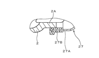
次に、カバー27の詳細について説明する。図2は、カバー27の側面近傍の部分的な拡大断面図である。また、図3はカバー27の端部近傍の部分的な拡大断面図である。
図2および図3に示すように、カバー27は、金属製のカバー本体27Aと、このカバー本体27Aの端部を覆うコーティング部27Bとからなっている。このコーティング部27Bは、カバー本体27Aよりも柔らかい材質、例えば樹脂材料によって形成されており、カバー本体27Aの端部から所定範囲の内周面および外周面を覆っている。
【0017】
また、カバー27の端部の内径は、組み付け時にこの端部に対応するリヤハウジング2の当接部2Aの外径よりも若干小さく、所定の締め代を持たせた寸法となっている。これにより、ボルト9にナット28を締め付けると、カバー27の端部のコーティング部27Bを径方向に沿ってリヤハウジング2の当接部2Aに押圧した状態でカバー27の組み付けが行われる。
【0018】
このように、金属製のカバー本体27Aの端部をこのカバー本体27Aよりも柔らかい樹脂製のコーティング部27Bで覆うことにより、カバー27の端部における振動をコーティング部27Bによって抑制することができる。また、コーティング部27Bによってカバー本体27Aの端部を覆うことにより、この端部の破損を防止することが可能になる。
【0019】
特に、上述した本実施形態の構造では、コーティング部27Bを介してカバー本体27A端部をリヤハウジング2の当接部2Aに押圧しているため、カバー本体27A端部を振動の固定端とすることによる振動の低減が可能であるとともに、この当接部2Aからカバー本体27Aに加わる応力を低減することが可能になってカバー27端部の亀裂や欠け等の破損を防止することができる。
【0020】
なお、本発明は上記実施形態に限定されるものではなく、本発明の要旨の範囲内において種々の変形実施が可能である。上述した実施形態では、カバー27の端部を径方向にリヤハウジング2の当接部2Aに当接させるようにしたが、軸方向に当接させるようにしてもよい。
【0021】
図4は、当接方向を変更したカバー27の側面近傍の部分的な拡大断面図である。また、図5は図4に示したカバー27の端部近傍の部分的な拡大断面図である。これらの図に示すように、リヤハウジング2には、軸方向端面2Cを有する当接部2Bが形成されている。これにより、ボルト9にナット28を締め付けると、カバー27の端部のコーティング部27Bを軸方向に沿ってリヤハウジング2の当接部2Bに押圧した状態でカバー27の組み付けが行われる。したがって、カバー27の端部を径方向にリヤハウジング2の当接部2Aに押圧した場合と同様に、カバー本体27A端部を振動の固定端とすることによる振動の低減が可能であるとともに、当接部2Bからカバー本体27Aに加わる応力を低減することが可能になってカバー27端部の亀裂や欠け等の破損を防止することができる。
【0022】
また、上述した実施形態では、カバー本体27Aの端部にコーティング部27Bを形成する範囲については特に言及していないが、カバー27に当接するリヤハウジング2の当接部2A、2Bが複数箇所に分かれて設けられている場合には、これら複数箇所の当接部2A、2Bに対応する位置のみにコーティング部27Bを分散して形成するようにしてもよい。これにより、カバー27の振動抑制と破損防止を実現しつつコーティング部27Bの面積を減らしてコストダウンをはかることが可能になる。
【0023】
また、上述した実施形態では、コーティング部27Bを樹脂材料を用いて形成した場合について説明したが、ゴム等の他の材質を用いるようにしてもよい。
【図面の簡単な説明】
【図1】一実施形態の車両用交流発電機の全体構成を示す図である。
【図2】カバーの側面近傍の部分的な拡大断面図である。
【図3】カバーの端部近傍の部分的な拡大断面図である。
【図4】当接方向を変更したカバーの側面近傍の部分的な拡大断面図である。
【図5】図4に示したカバーの端部近傍の部分的な拡大断面図である。
【符号の説明】
1 フロントハウジング
2 リヤハウジング
2A、2B 当接部
2C 軸方向端面
4 固定子
10 回転子
24 整流装置
25 電圧制御装置
26 ブラシ装置
27 カバー
27A カバー本体
27B コーティング部
100 車両用交流発電機[0001]
TECHNICAL FIELD OF THE INVENTION
The present invention relates to a vehicle alternator mounted on a passenger car, a truck, and the like.
[0002]
[Prior art]
Some conventional AC generators for vehicles include a metal cover for protecting electric components such as a rectifier and a brush device (for example, see Patent Document 1). This cover is manufactured, for example, by press-forming an iron plate or an aluminum plate. However, since a thin plate material is used, the flat portion is likely to vibrate and may be a noise source. For this reason, there is a method of suppressing the vibration of the cover itself by pressing the cover end against the rear housing by assembling with an appropriate interference between the cover end and the aluminum die-cast rear housing. It has been used conventionally.
[0003]
[Patent Document 1]
JP 2001-37142 A (page 3-4, FIG. 1-3)
[0004]
[Problems to be solved by the invention]
By the way, in the conventional vehicle alternator described above, the end of the metal cover is pressed against the rear housing for the purpose of suppressing vibration, and both the cover and the rear housing, which are the pressed portions, are made of metal. It is hard and causes a large stress to be generated on the cover side made of thin plate material. Especially, when an automotive alternator is mounted on an engine that generates large vibrations, cracks or chippings occur at the end of the cover. There is a problem that damage such as the like may occur.
[0005]
The present invention has been made in view of the above points, and an object of the present invention is to provide a vehicle AC that can prevent vibration of a metal cover and prevent breakage such as a crack or a chip at an end. It is to provide a generator.
[0006]
[Means for Solving the Problems]
In order to solve the above-described problems, a vehicular alternator of the present invention includes a housing for holding a rotor and a stator, an electric component attached to the outside of the housing, and a metal cover for covering the electric component. The cover includes a metal cover main body and a coating portion that covers an end of the cover main body with a material softer than the cover main body. By covering the end of the metal cover main body with a coating portion softer than the cover main body, it is possible to suppress vibration at the end and prevent breakage such as cracks and chips.
[0007]
Further, it is desirable that the above-mentioned cover is assembled in a state where the coating portion is pressed against the housing along the radial direction. Alternatively, it is desirable that the above-described cover is assembled with the coating portion pressed against the housing along the axial direction. By pressing the coating portion provided at the end of the cover against the housing in the radial direction or the axial direction, the coating portion can be absorbed and suppressed. Further, by pressing the cover end portion against the housing via the coating portion, the stress generated at the cover end portion by the coating portion is relieved, so that damage such as cracking or chipping at the cover end portion can be prevented. it can.
[0008]
Further, it is desirable that the material of the above-mentioned coating portion is a resin. Since the coating portion can be formed with a resin that is softer than the metal that is the material of the cover main body and the cover end portion can be pressed, vibration suppression and breakage of the cover can be reliably achieved.
[0009]
Further, the end of the cover and the housing are in contact with each other at a plurality of contact portions, and the coating portion is desirably formed at a plurality of locations corresponding to the plurality of contact portions. As a result, it is possible to reduce the area of the coating portion and reduce costs while realizing vibration suppression and breakage prevention of the cover.
[0010]
BEST MODE FOR CARRYING OUT THE INVENTION
Hereinafter, an automotive alternator according to an embodiment of the present invention will be described in detail with reference to the drawings.
FIG. 1 is a diagram illustrating an overall configuration of an automotive alternator according to an embodiment. The
[0011]
The front housing 1 and the
[0012]
The stator 4 includes a stator core 5 and a stator winding 6.
The
[0013]
So-called electric components such as a
[0014]
The
[0015]
In the
[0016]
Next, details of the
As shown in FIGS. 2 and 3, the
[0017]
The inner diameter of the end of the
[0018]
As described above, by covering the end of the metal cover
[0019]
In particular, in the above-described structure of the present embodiment, since the end of the
[0020]
Note that the present invention is not limited to the above embodiment, and various modifications can be made within the scope of the present invention. In the above-described embodiment, the end of the
[0021]
FIG. 4 is a partially enlarged cross-sectional view near the side surface of the
[0022]
In the above-described embodiment, the range in which the
[0023]
Further, in the above-described embodiment, the case where the
[Brief description of the drawings]
FIG. 1 is a diagram illustrating an overall configuration of an automotive alternator according to an embodiment.
FIG. 2 is a partially enlarged cross-sectional view near a side surface of a cover.
FIG. 3 is a partially enlarged cross-sectional view near an end of a cover.
FIG. 4 is a partially enlarged cross-sectional view of the vicinity of a side surface of a cover in which a contact direction is changed.
FIG. 5 is a partially enlarged cross-sectional view near the end of the cover shown in FIG. 4;
[Explanation of symbols]
DESCRIPTION OF SYMBOLS 1
Claims (5)
前記カバーは、前記金属製のカバー本体と、このカバー本体よりも柔らかい材質で前記カバー本体の端部を覆うコーティング部とを備えることを特徴とする車両用交流発電機。In a vehicle AC generator having a housing that holds a rotor and a stator, an electric component attached to the outside of the housing, and a metal cover that covers the electric component,
The alternator for a vehicle, wherein the cover includes: the cover body made of metal; and a coating portion that is made of a material softer than the cover body and covers an end of the cover body.
前記カバーは、径方向に沿って前記コーティング部を前記ハウジングに対して押圧した状態で組み付けられていることを特徴とする車両用交流発電機。In claim 1,
The alternator for a vehicle, wherein the cover is assembled in a state where the coating portion is pressed against the housing along a radial direction.
前記カバーは、軸方向に沿って前記コーティング部を前記ハウジングに対して押圧下状態で組み付けられていることを特徴とする車両用交流発電機。In claim 1 or 2,
The alternator for a vehicle, wherein the cover is assembled in a state where the coating portion is pressed against the housing along an axial direction.
前記コーティング部の材質は樹脂であることを特徴とする車両用交流発電機。In any one of claims 1 to 3,
The alternator for a vehicle, wherein the material of the coating portion is a resin.
前記カバーの端部と前記ハウジングは複数の当接部において当接しており、
前記コーティング部は、複数の前記当接部に対応する複数箇所において分散して形成されていることを特徴とする車両用交流発電機。In any one of claims 1 to 4,
The end of the cover and the housing are in contact at a plurality of contact portions,
The alternator for a vehicle, wherein the coating portion is formed separately at a plurality of locations corresponding to the plurality of contact portions.
Priority Applications (1)
| Application Number | Priority Date | Filing Date | Title |
|---|---|---|---|
| JP2003032384A JP2004248338A (en) | 2003-02-10 | 2003-02-10 | Alternator for vehicle |
Applications Claiming Priority (1)
| Application Number | Priority Date | Filing Date | Title |
|---|---|---|---|
| JP2003032384A JP2004248338A (en) | 2003-02-10 | 2003-02-10 | Alternator for vehicle |
Publications (1)
| Publication Number | Publication Date |
|---|---|
| JP2004248338A true JP2004248338A (en) | 2004-09-02 |
Family
ID=33018748
Family Applications (1)
| Application Number | Title | Priority Date | Filing Date |
|---|---|---|---|
| JP2003032384A Withdrawn JP2004248338A (en) | 2003-02-10 | 2003-02-10 | Alternator for vehicle |
Country Status (1)
| Country | Link |
|---|---|
| JP (1) | JP2004248338A (en) |
Cited By (3)
| Publication number | Priority date | Publication date | Assignee | Title |
|---|---|---|---|---|
| JP2007143296A (en) * | 2005-11-18 | 2007-06-07 | Nabtesco Corp | Motor |
| WO2011148825A1 (en) * | 2010-05-26 | 2011-12-01 | 日立オートモティブシステムズ株式会社 | Rotary electric machine |
| WO2013157096A1 (en) * | 2012-04-18 | 2013-10-24 | 三菱電機株式会社 | Ac generator |
-
2003
- 2003-02-10 JP JP2003032384A patent/JP2004248338A/en not_active Withdrawn
Cited By (9)
| Publication number | Priority date | Publication date | Assignee | Title |
|---|---|---|---|---|
| JP2007143296A (en) * | 2005-11-18 | 2007-06-07 | Nabtesco Corp | Motor |
| WO2011148825A1 (en) * | 2010-05-26 | 2011-12-01 | 日立オートモティブシステムズ株式会社 | Rotary electric machine |
| JP2011250562A (en) * | 2010-05-26 | 2011-12-08 | Hitachi Automotive Systems Ltd | Rotary electric machine |
| CN102906975A (en) * | 2010-05-26 | 2013-01-30 | 日立汽车系统株式会社 | Rotary electric machine |
| WO2013157096A1 (en) * | 2012-04-18 | 2013-10-24 | 三菱電機株式会社 | Ac generator |
| CN104170218A (en) * | 2012-04-18 | 2014-11-26 | 三菱电机株式会社 | AC generator |
| JP5752320B2 (en) * | 2012-04-18 | 2015-07-22 | 三菱電機株式会社 | AC generator |
| CN104170218B (en) * | 2012-04-18 | 2017-03-01 | 三菱电机株式会社 | Alternating current generator |
| US10411551B2 (en) | 2012-04-18 | 2019-09-10 | Mitsubishi Electric Corporation | AC generator with stackable protective cover |
Similar Documents
| Publication | Publication Date | Title |
|---|---|---|
| JP4858505B2 (en) | Rotating electric machine for vehicles | |
| JP3379457B2 (en) | AC generator for vehicles | |
| JP2008061293A (en) | Vehicle ac generator | |
| JP4382464B2 (en) | Vehicle alternator | |
| JP3876912B2 (en) | AC generator for vehicles | |
| JP4640122B2 (en) | AC generator for vehicles | |
| EP1246347B1 (en) | Vehicle AC generator | |
| JP4775654B2 (en) | AC generator for vehicles | |
| JP5007537B2 (en) | AC generator for vehicles | |
| JP3982369B2 (en) | AC generator for vehicles | |
| JP2004248338A (en) | Alternator for vehicle | |
| JP2007028832A (en) | Ac generator for vehicle | |
| US7554233B2 (en) | On-vehicle alternator capable of adjustably orienting output cable | |
| US7633196B2 (en) | Vehicle-use alternator | |
| JP2004080854A (en) | Rotary machine for vehicle | |
| JP3966212B2 (en) | AC generator for vehicles | |
| JP4692439B2 (en) | AC generator for vehicles | |
| JP2002119029A (en) | Ac generator for vehicle | |
| JP4609445B2 (en) | AC generator for vehicles | |
| JP2010063250A (en) | Rotating electric machine for vehicle | |
| JP2008061292A (en) | Vehicle ac generator | |
| JP3794366B2 (en) | AC generator for vehicles | |
| JP4211219B2 (en) | Vehicle alternator | |
| JP4403950B2 (en) | Rotating electric machine | |
| JP4400010B2 (en) | Rotating electric machine |
Legal Events
| Date | Code | Title | Description |
|---|---|---|---|
| A621 | Written request for application examination |
Effective date: 20050318 Free format text: JAPANESE INTERMEDIATE CODE: A621 |
|
| A761 | Written withdrawal of application |
Free format text: JAPANESE INTERMEDIATE CODE: A761 Effective date: 20060328 |