JP2004246359A - Method for repairing gradient-matched cable system and cable part for replacement used for same - Google Patents
Method for repairing gradient-matched cable system and cable part for replacement used for same Download PDFInfo
- Publication number
- JP2004246359A JP2004246359A JP2004033114A JP2004033114A JP2004246359A JP 2004246359 A JP2004246359 A JP 2004246359A JP 2004033114 A JP2004033114 A JP 2004033114A JP 2004033114 A JP2004033114 A JP 2004033114A JP 2004246359 A JP2004246359 A JP 2004246359A
- Authority
- JP
- Japan
- Prior art keywords
- cable
- length
- replacement
- repair
- repeater
- Prior art date
- Legal status (The legal status is an assumption and is not a legal conclusion. Google has not performed a legal analysis and makes no representation as to the accuracy of the status listed.)
- Pending
Links
Images


Classifications
-
- G—PHYSICS
- G02—OPTICS
- G02B—OPTICAL ELEMENTS, SYSTEMS OR APPARATUS
- G02B6/00—Light guides; Structural details of arrangements comprising light guides and other optical elements, e.g. couplings
- G02B6/46—Processes or apparatus adapted for installing or repairing optical fibres or optical cables
- G02B6/56—Processes for repairing optical cables
- G02B6/564—Repair sets
Abstract
Description
本発明は、光ファイバ・ケーブル・システムの修理に関し、より詳細には、分散勾配整合型ケーブルを使用する海底ケーブル・システムの修理に関する。 The present invention relates to the repair of fiber optic cable systems, and more particularly, to the repair of submarine cable systems that use distributed gradient matched cables.
光ファイバ・ケーブル・システムは、複数の光ファイバを含むケーブルと、ケーブル長さに沿って周期的に配置された複数の光増幅器を含むリピータとから構成される。光ファイバ・ケーブル・システムはまた、ケーブル長さに沿って周期的に配置された複数の利得等化器を含むことがある。そのようなシステムの1つの重要なパラメータは色分散であり、これはさまざまな波長の光が光ファイバに沿って進行する速度に関係する。システムの伝送性能を最適化すべき場合、システムの長さの関数としての分散を管理する必要がある。1つの管理方法は勾配整合型ケーブルを使用することであり、その場合、システム内の各ファイバ経路の正味の端から端までの分散は伝送帯域にわたって公称上一定であり、温度によって変化しない。 An optical fiber cable system comprises a cable including a plurality of optical fibers and a repeater including a plurality of optical amplifiers periodically arranged along a length of the cable. Fiber optic cable systems may also include a plurality of gain equalizers periodically arranged along the length of the cable. One important parameter of such a system is chromatic dispersion, which is related to the speed at which various wavelengths of light travel along the optical fiber. If the transmission performance of the system is to be optimized, it is necessary to manage the variance as a function of the length of the system. One method of management is to use gradient matched cables, where the net end-to-end dispersion of each fiber path in the system is nominally constant over the transmission band and does not change with temperature.
通常の高密度波長分割多重(DWDM)の海底用勾配整合型ケーブル・システムでは、「正規の」もしくは「伝送の」ケーブル区画(「ケーブル区画」は隣り合うリピータの間のケーブルを称する)はN型およびP型のファイバで構成される。これらN型およびP型のファイバはそれぞれ大幅に負および正の分散率(対距離)を有するが、名目上で一定の正味の分散(たとえば−3ps/nm・km2の率)を達成するような比である。分散の整合は波長と温度の両方の関数として厳密に持続することが好ましい。 In a typical dense wavelength division multiplexed (DWDM) submarine gradient-matched cable system, the "regular" or "transmission" cable section (the "cable section" refers to the cable between adjacent repeaters) is N It consists of a type and a P type fiber. These N-type and P-type fibers have significant negative and positive dispersion ratios (distance), respectively, but are intended to achieve a nominally constant net dispersion (eg, a rate of -3 ps / nm · km 2 ). Ratio. Preferably, the dispersion match lasts strictly as a function of both wavelength and temperature.
図1を参照すると、P型のファイバ12を表わす太い線とN型のファイバ14を表わす細い線で正規のケーブル区画10の1つのファイバ対の構成が示されている。1つのファイバ対が示されているけれども、実際の区画は、通常、多数のファイバ対を含む。図1で、上側のファイバ経路では光信号は左から右へと伝搬され、下側のファイバ経路では右から左へと伝搬される。勾配整合型ケーブル区画10は、全数P型のファイバ12を含む中央部分16、およびP型とN型の両方のファイバ12、14を含む両端部分18a、18bを含む。N型ファイバの一例はIDFX2という記号表示でLucent社から入手可能である。P型ファイバの一例はSLAという記号表示でLucent社から入手可能である。正規のケーブル区画では、P型ファイバ12とN型ファイバ14は、通常、スプライス損失を最小限にするためにブリッジ・ファイバを使用してファイバ工場で一体にスプライスされる。
Referring to FIG. 1, the configuration of one fiber pair of a
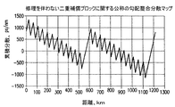
正規のケーブル区画に加えて、システムの分散特性を適切に管理するために、全数P型のファイバを含む補償ケーブル区画(図示せず)が使用される可能性がある。勾配整合型ケーブル・システムの一例では、システムの長さに沿って450〜500km毎に直列になった2つまたは3つの「補償」ケーブル区画が使用される。図2は、(正規および補償のケーブル区画を使用する)理想的な二重補償のブロック長さに関する分散マップを示している。 In addition to regular cable sections, compensating cable sections (not shown) containing all P-type fibers may be used to properly manage the dispersion characteristics of the system. One example of a gradient matched cable system uses two or three "compensated" cable sections in series every 450-500 km along the length of the system. FIG. 2 shows a dispersion map for ideal double compensated block lengths (using regular and compensated cable sections).
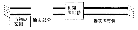
それとは別に、システムの利得等化が、利得勾配を補正するたとえば利得等化器連結部(GEJ)の形でリピータにおいて使用されることが可能であり、非平坦利得形状を補正する形状補償ユニット(SCU)がそれら独自のハウジング内に設置されて補償ケーブル区画に配置されることが可能である。システムの分散を適切に管理するために、いくつかの補償ケーブル区画は正規のケーブル区画よりもかなり短く、かつ中間区画の損失付け足し部(LBO)を含む可能性がある。LBOはスプライス・ボックス内である程度の光学的減衰を故意に挿入され、それによりケーブル区画の設計値に損失を付け足す。スプライス・ボックスはケーブル間連結部でファイバ・スプライスを収納するために使用される主要装置である。 Alternatively, the gain equalization of the system can be used in a repeater, for example in the form of a gain equalizer junction (GEJ) to correct the gain gradient, and a shape compensation unit to correct the non-flat gain shape (SCUs) can be located in their own housing and located in the compensation cable compartment. In order to properly manage the dispersion of the system, some compensating cable sections are significantly shorter than regular cable sections and may include an intermediate section loss adder (LBO). The LBO is deliberately inserted into the splice box with some optical attenuation, thereby adding loss to the design of the cable section. Splice boxes are the primary equipment used to house fiber splices at cable-to-cable connections.
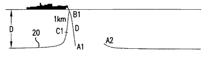
ケーブル・システムはしばしば故障を生じ、修理を必要とする。故障はケーブルの部分またはケーブルに接続されたリピータで生じる可能性がある。図3〜6を参照すると、海底ケーブル20の故障部分を交換するための修理操作が極めて詳細に示されている。通常の海底での修理操作はケーブル20を切断してケーブル20の「良品」端部と予測される部分を回収することによって始まる。概して、ケーブルは切断部からおよそ水深D離れた場所B1で係合され、それにより、回収時に両側に同じ重量がかかる(図4参照)。結果として、元のケーブル区画の少なくとも水深長さD1つ分が除去される。切断端部からコア・ケーブル構造内への水の浸入が理由で、さらなるケーブル(たとえば最長で1km)が除去される可能性もある。このケーブルが除外された後、ケーブル20の端部B1はシールされてブイで浮かべられる(図5参照)。その後、他方のケーブル端部A2が回収され、元のケーブル20の水深Dもしくはそれ以上の長さが除去される。故障は好ましくは、除去したケーブル20のうちの1本にある。そうでない場合、ケーブルが故障部分を越えて切断されるまでさらなるケーブルが回収される。故障を生じたリピータが交換される場合、それが船上に上がるまでケーブルが回収され、そこでそれは切り離されて予備のリピータと交換される。
Cable systems often fail and require repair. Failures can occur in parts of the cable or in repeaters connected to the cable. Referring to FIGS. 3-6, a repair operation for replacing a failed portion of the
その後、予備のケーブルがケーブル20の「良品」端部に接続される。予備ケーブルの長さは除去された元のケーブルに加えて通常は水深の2〜2.5倍の追加長さに置き換わるのに充分であることが好ましく、それにより、ケーブルの湾曲が船外に出る前に最終連結部を作製することが可能となる(図6参照)。いくつかの既存のブロードバンド・システムについては、修理の結果として生じる追加損失に起因して発生する伝送利得形状(すなわち利得勾配)の変化を回避するために修理リピータと呼ばれる追加のリピータを交換用ケーブルに挿入することが賢明である。以上で検討した修理操作に基づくと、修理時に使用される予備ケーブルの最低量(すなわち交換部分)はしばしば修理現場の水深の4.5倍である。他の良品ケーブルへの水の浸入に起因するか、最初に回収ケーブルに故障が見つからないか、または故障リピータが回収されるときにさらにケーブルが除去される場合、交換部分はさらに長くなる可能性すらある。
Thereafter, a spare cable is connected to the “good” end of
修理の後の端から端までの正味のシステムの分散が不変を保たなければならないので、勾配整合システムの修理は困難を呈する可能性がある。たとえ交換区画が除去されたものと同じケーブル・タイプを使用しても、追加のケーブル長さは伝送の双方向で分散をかなり不釣合いにするであろう。 Repair of gradient matching systems can present difficulties as the net system variance across the repair must remain unchanged. Even with the same cable type from which the switching section was removed, the additional cable length would significantly disperse the dispersion in both directions of transmission.
したがって、補償ケーブル区画で修理が為されるときでさえ、修理の後の端から端までの正味のシステムの分散を伝送の双方向で名目上不変に保つことを可能にする勾配整合型ケーブル・システムを修理する方法が必要とされる。勾配整合型ケーブル・システムを修理する方法はまた、それが伝送スペクトルにわたって利得勾配を名目上不変に保つようにされることが好ましい。 Thus, even when repairs are made in the compensating cable section, a gradient matched cable that allows the net system dispersion to remain nominally unchanged in both directions of transmission after the repair. What is needed is a way to repair the system. Preferably, the method of repairing a gradient matched cable system is also such that it keeps the gain gradient nominally unchanged over the transmission spectrum.
上述の要求に対応するために、ケーブル・システム内の正味の分散を名目上不変に保つ交換用ケーブル部分を使用して勾配整合型ケーブル・システムが修理される。本発明の一態様によると、負の分散率を有する少なくとも1本のN型ファイバと正の分散率を有する少なくとも1本のP型ファイバを含む勾配整合型ケーブル・システムを修理するためにある方法が使用される。本方法は勾配整合型ケーブル・システムの故障部分を除去する工程を含む。第1および第2のN−Pケーブル長さは少なくとも1本のN型ファイバと少なくとも1本のP型ファイバを含む予備のN−Pケーブルから供給される。少なくとも第1と第2のP型ファイバを含む予備のPケーブルから少なくとも1本の全数(all)−Pケーブル長さが供給される。交換用ケーブル部分はN−Pケーブル長さと全数−Pケーブル長さから構成され、そこではN−Pケーブル長さはPケーブル長さの両側に接続される。修理時に、交換用ケーブル部分は当初設置された勾配整合型ケーブルの故障部分が除去された端部間に接続される。本方法はまた、ケーブルの故障を修理するときに修理リピータを交換用ケーブル部分の一方の端部に接続する工程および/または交換用利得等化器を交換用ケーブル部分に接続する工程も含む可能性がある。本方法は、リピータの故障を修理するときに交換用ケーブル部分の一方の端部に交換用リピータを接続し、他方の端部に修理リピータを接続する工程を含む。 To meet the above demands, gradient matched cable systems are repaired using replacement cable sections that keep the net distribution in the cable system nominally unchanged. According to one aspect of the present invention, a method for repairing a gradient matched cable system including at least one N-type fiber having a negative dispersion and at least one P-type fiber having a positive dispersion is provided. Is used. The method includes removing faulty portions of the gradient matched cable system. The first and second NP cable lengths are supplied from a spare NP cable including at least one N-type fiber and at least one P-type fiber. At least one all-P cable length is provided from a spare P cable including at least first and second P-type fibers. The replacement cable portion comprises an NP cable length and an all-P cable length, where the NP cable length is connected to both sides of the P cable length. During repair, the replacement cable section is connected between the ends of the originally installed gradient-matched cable where the faulty section has been removed. The method may also include connecting a repair repeater to one end of the replacement cable portion when repairing a cable failure and / or connecting a replacement gain equalizer to the replacement cable portion. There is. The method includes connecting a replacement repeater to one end of a replacement cable portion and connecting a repair repeater to the other end when repairing a repeater failure.
本発明の別の態様によると、交換用ケーブル部分は半数(half)のN型ファイバ群と半数のP型ファイバ群を含む第1と第2のN−Pケーブル長さ、および全数−P型のファイバ群を含む少なくとも1本のPケーブル長さを有する。N型ファイバは負の分散率を有し、P型ファイバは正の分散率を有する。第1のスプライス・ボックスは第1のN−Pケーブル長さとPケーブル長さとを接続する。第1のN−Pケーブル長さの中のN型ファイバはPケーブル長さの中の複数のP型ファイバの第1の半数にスプライスされる。第1のN−Pケーブル長さの中のP型ファイバはPケーブル長さの中の複数のP型ファイバの第2の半数にスプライスされる。第2のスプライス・ボックスは第1のN−Pケーブル長さとPケーブル長さとを接続する。第1のN−Pケーブル長さの中のN型ファイバはPケーブル長さの中の複数のP型ファイバの第1の半数にスプライスされる。第1のN−Pケーブル長さの中のP型ファイバはPケーブル長さの中の複数のP型ファイバの第2の半数にスプライスされる。交換用ケーブル部分は、その交換用ケーブル部分で修理されるときにシステム内の各々のファイバ経路の正味の分散と利得形状が名目上不変を保つように設計されることが好ましい。利得形状は、交換部分に適切な損失付け足し部(LBO)を備えた修理リピータ(および必要時に交換用リピータ)を含ませることによって維持されることが好ましい。 In accordance with another aspect of the invention, the replacement cable portion includes first and second NP cable lengths including half of the N-type fiber groups and half of the P-type fiber groups, and all-P type. Has at least one P-cable length that includes N-type fibers have a negative dispersion and P-type fibers have a positive dispersion. The first splice box connects the first NP cable length and the P cable length. The N-type fiber in the first NP cable length is spliced to a first half of the plurality of P-type fibers in the P cable length. P-type fibers in the first NP cable length are spliced to a second half of the plurality of P-type fibers in the P cable length. A second splice box connects the first NP cable length and the P cable length. The N-type fiber in the first NP cable length is spliced to a first half of the plurality of P-type fibers in the P cable length. P-type fibers in the first NP cable length are spliced to a second half of the plurality of P-type fibers in the P cable length. The replacement cable section is preferably designed such that when repaired with the replacement cable section, the net dispersion and gain shape of each fiber path in the system remains nominally unchanged. The gain shape is preferably maintained by including a repair repeater (and a replacement repeater if necessary) with an appropriate loss adder (LBO) in the replacement part.
本発明のこれらおよびその他の特徴は、図面と一体化して為される以下の詳細な説明を読むことによってさらによく理解されるであろう。 These and other features of the present invention will be better understood by reading the following detailed description, taken in conjunction with the drawings.
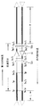
図7を参照すると、勾配整合型ケーブル・システムの修理に使用される交換用ケーブル部分30の一実施形態が示されている。下記でさらに詳細に説明するように、交換用ケーブル部分30は(N型とP型の両方のファイバを有する)正規のケーブル区画または(全数P型のファイバを有する)補償ケーブル区画を修理するのに使用されることが可能である。交換用ケーブル部分30はまた、修理リピータ、交換用リピータ、利得等化器連結部(GEJ)のような利得等化器と形状補償ユニット(SCU)、あるいはその他の部品を備えても備えなくても使用されることが可能である。範例の方法は海底環境の勾配整合型ケーブル・システムの修理のためのものであるが、本方法と交換用ケーブル部分30は、かなりの量の余分のケーブルが修理で追加される必要のある他の環境で勾配整合型ケーブル・システムを修理するために使用されることもやはり可能である。
Referring to FIG. 7, one embodiment of a
概して、勾配整合型ケーブルを修理する方法は、勾配整合型ケーブル・システムの故障を生じた部分を除去する工程、交換用ケーブル部分を作製する工程、および故障発生部分が除去された場所で勾配整合型ケーブルに交換用ケーブル部分を接続する工程を含む。ケーブル・システムの故障発生部分はケーブル内の故障またはリピータ内の故障を有する可能性がある。交換用ケーブル部分は予備のN−Pケーブルと予備のPケーブルから構成され、修理リピータ、交換用リピータ、LBO、および/または交換用等化器ユニットを有することもやはり可能である。 In general, the method of repairing a gradient matched cable includes removing the failed portion of the gradient matched cable system, making a replacement cable portion, and gradient matching at the location where the failed portion was removed. Connecting the replacement cable portion to the mold cable. The faulty portion of the cable system may have a fault in the cable or a fault in the repeater. The replacement cable section is comprised of a spare NP cable and a spare P cable, and may also include a repair repeater, a replacement repeater, an LBO, and / or a replacement equalizer unit.
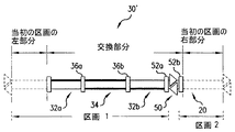
交換用ケーブル部分30はPケーブル長さ34の両端部に接続された第1と第2のN−Pケーブル長さ32a、32bを含む。N−Pケーブル長さ32a、32bは、スプライス・ボックス36a、36bを含むケーブル接続部を使用してPケーブル長さ34に接続されることが好ましい。交換用ケーブル部分30はまた、N−Pケーブル長さ32a、32bの両端部で、スプライス・ボックス(図示せず)を使用して当初のケーブル区画(図示せず)の間に接続される可能性もある。ケーブルの接続およびファイバのスプライス処理は当業者によく知られており、既にある接続器およびスプライス・ボックスが使用されることが可能である。
The
N−Pケーブル長さ32a、32bは、負の分散率を有する半数のN型ファイバ群40と正の分散率を有する半数のP型ファイバ群42を含む1つのタイプの予備のケーブルから作製される。全数−Pケーブル長さ34は全数−P型のファイバ群42を含む予備のケーブルの他のタイプから作製される。N型ファイバ40の一例は、IDFX2の記号表示でLucent社から入手可能なタイプのように公称−40ps/nm・kmの負の分散率を有する。P型ファイバ42の一例は、SLAの記号表示でLucent社から入手可能なタイプのように公称20ps/nm・kmの正の分散率を有する。図7は各々のケーブル長さ32a、32b、34のファイバの一対だけを示しているが、通常のケーブルは多数のファイバ対を有するであろう。他の分散率もやはり考慮される。
The
予備ケーブルの2つのタイプ(すなわちN−Pケーブル長さ32a、32bとPケーブル長さ34)は、補償ケーブル区画で修理が為されるときでさえ修理の後の正味の名目上の分散を実質的に不変に保つ比で組み合わされる。図8は、修理された正規のケーブル区画の修理されたファイバ経路の分散と比較したときの正規のケーブル区画の元のファイバ経路の分散を示している。勾配整合システム内のケーブルを修理するために交換用ケーブル部分30が使用されると、修理されたファイバ経路の正味の分散は元のファイバ経路のそれに名目上等しくされることが可能である。
The two types of spare cables (i.e.,
交換用ケーブル部分30を作製するのに使用される予備のケーブルの長さ32a、32b、34は、修理完了後の勾配整合型ケーブル・システム全体の分散が名目上不変であるように計算される。これらの長さを計算する1つの方法は下記でさらに詳細に述べられる。下記の計算の目的のために、分散[ps/nm]はΔを使用して記され、分散率対距離[ps/(nm・km)]はDを使用して記される。「分散」という用語は、ここでは両方の概念について使用される可能性がある。「東向き」および「西向き」という用語は、ここでは伝送の2つの方向、およびそれに相当して正規のケーブル区画で見られるファイバの2つの配列を区別するために使用される。ここで使用するように東向きと西向きは必ずしも磁石の方向に対応するものではない。
The
修理時では、ある程度の当初のケーブル区画の除去の結果としてシステムから取られる分散は置き換えられる必要があり、ケーブル長さが追加されなければならない。当初のケーブルが切断されて故障を伴ったケーブルの部分が除去された後、勾配整合型ケーブル・システムから除去された当初のケーブルの量とタイプが判定される。除去された東向き伝送ファイバの長さはP型のXpeおよびN型のXneと規定される。同様に、除去された西向き伝送ファイバの長さはP型のXpwおよびN型のXnwと規定される。これらのファイバはすべて同じケーブル内にあるので、
Xpe+Xne=Xpw+Xnw 式1
である。修理時に(Xpe+Xneに加えて)追加される余分のケーブルの長さはδとして提供される。
During repair, the variance taken from the system as a result of some initial cable section removal needs to be replaced, and the cable length must be added. After the original cable has been cut and the faulty cable portion removed, the amount and type of the original cable removed from the gradient matched cable system is determined. The length of the removed east transmission fiber is defined as P-type X pe and N-type X ne. Similarly, the length of the stripped westbound transmission fiber is defined as P-type Xpw and N-type Xnw . Since all of these fibers are in the same cable,
Xpe + Xne = Xpw + Xnw Formula 1
It is. The extra cable length added during repair (in addition to Xpe + Xne) is provided as δ.
東向きの方向で、システムから除去される分散の量は、好ましくは置き換えられるべき量であって、
Δre=DpXpe+DnXne 式2
であり、ここで
Dp=P型ファイバの分散率、および
Dn=N型ファイバの分散率である。
図9を参照すると、交換用ケーブル部分30のファイバ対の一般的構造が示されており、P型ファイバが太い線で表わされ、N型ファイバが細い線で表わされている。Ypeを交換用ケーブル部分30の合計長さの東向き方向のP型ファイバの長さとする。そのとき、
YpeDp+(Xpe+Xne+δ−Ype)Dn=Δre 式3
である、式2と3を組み合わせると、

西向きの方向について同様の分析が実行されるならば、交換用ケーブル部分30内のP型ファイバの長さは、
Δ re = D p X pe + D n
Where D p = dispersion rate of P-type fiber and D n = dispersion rate of N-type fiber.
Referring to FIG. 9, the general structure of a fiber pair in the
Y pe D p + (X pe + X ne + δ−Y pe ) D n = Δre
Combining
If a similar analysis is performed for the westward direction, the length of the P-type fiber in the
上記で検討したように、交換用ケーブル部分30は3つのケーブル長さ32a、32b、34を有し、修理を完了させるために4つの接続部が使用される(図7参照)。以上の式に基づくと、N−P予備ケーブル長さの一方32aはYnwの長さであり、N−P予備ケーブル長さの他方32bはYneの長さである。P予備ケーブル34は(Ype−Ynw)の長さを有し、それはやはり(Ypw−Yne)にも等しい。
As discussed above, the
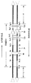
追加の実施形態をここで説明するが、そこでは類似するかもしくは同様の素子は図中で同じ参照番号で識別される。図10に示された別の交換用ケーブル部分30’はN−Pケーブル長さの一方32bの一方の端部に接続された修理リピータ50を含む。修理リピータ50は、たとえば、別の方法では余分のケーブルとスプライスの5dB以上の損失の追加の結果として導入される多量の利得勾配を回避するために、勾配整合型ケーブル・システムの深海修理に使用されることが好ましい。光増幅器は隣り合うリピータの利得を上げることによって自動的にケーブル区画内の追加損失を補償するけれども、公称のシステム設計値と比べてリピータの入力パワーが下げられる(または上げられる)と利得勾配が導入される。これはさらに広い伝送帯域にとって特に厄介である。たとえば26nm帯域幅では、利得勾配は1dB毎に0.5dBを超える余分の損失となる可能性があり、勾配整合型ケーブル修理に加えられる余分の損失は通常の5kmの修理深さについて5dBを超える可能性がある。追加的な損失は追加されたケーブル長さ(たとえば水深の2〜2.5倍)、N型ファイバの比較的高い減衰度、およびスプライスの数といくつかのファイバ・タイプの間の高いスプライス損失から結果として生じる。修理リピータ50は、たとえばシステムの組み立て時に装備されるLBOの大きな値が修理の間に除去されるならば確実な修理に必要とされない可能性がある。
Additional embodiments are described herein, wherein similar or similar elements are identified by the same reference numerals in the figures. Another replacement cable section 30 'shown in FIG. 10 includes a
修理リピータ50はN−P予備ケーブル長さ32bと当初のケーブル20の間にスプライス・ボックス52a、52bを使用して結合される。修理リピータ50の追加は2つのケーブル区画を作り出し、そこでは一方のケーブル区画は修理の前に存在する。2つの新たなケーブル区画の損失はケーブル区画に関する公称の設計損失に等しくされることができない可能性はあるけれども、各々のファイバ経路について2つの新たなケーブル区画の組み合わせ損失は単一のケーブル区画の公称設計損失の2倍に近くされ得ることが好ましい。所望の設計損失を達成するために、スプライス・ボックスは損失付け足し部(LBO)を含むことが好ましく、LBOの値は、2つの区画の損失の間の差異を最小限にしながら望ましい公称設計損失を達成するように選択され、その結果システムの伝送スペクトルの端から端までの利得形状が修理による変化を名目上受けずに保たれることを確実化することが可能となる。理想的なLBO値を選択する1つの方法は下記でさらに詳細に述べられる。
The
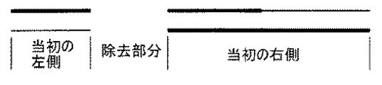
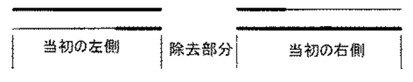
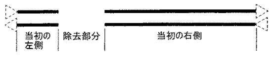
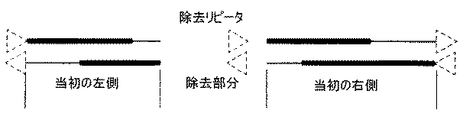
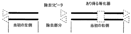
さらに詳細に修理の方法を説明する目的で、ケーブル区画の「左」側は端部が回収されて故障が取り除かれた後のさらに低い損失を有する残りの当初のケーブル区画(普通はさらに短い長さ)に相当する。「右」側は残りの当初のケーブルの他方の半分を称する。「東向き」の伝送方向は左から右であり、「西向き」の伝送方向は右から左である。 For the purpose of explaining the repair process in more detail, the "left" side of the cable section is the remaining original cable section (usually a shorter length) with lower losses after the ends have been recovered and the fault has been removed. ). The "right" side refers to the other half of the remaining original cable. The transmission direction "eastward" is from left to right, and the transmission direction "westward" is right to left.
正味の損失は当初の区画と交換部分について計算され、理想的なLBO値は修理リピータのいずれの交換についても計算される。理想的なLBO値は伝送のいずれの方向、東向き(すなわち図で左から右)および西向き(すなわち図で右から左)についても計算される。理想的なLBO値を計算するための式はまた、修理される当初のケーブル区画の残る部分に工場装備のLBOがないことも想定している。LBOが工場装備されて当初の残りの左と右のケーブル部分に配置されている場合、それらは計算に含まれるべきであることが好ましい。 The net loss is calculated for the original parcel and the replacement part, and the ideal LBO value is calculated for any replacement of the repair repeater. The ideal LBO value is calculated for any direction of transmission, eastward (ie, left to right in the figure) and westward (ie, right to left in the figure). The formula for calculating the ideal LBO value also assumes that there is no factory installed LBO in the rest of the original cable section to be repaired. If LBOs are factory-installed and placed in the original remaining left and right cable sections, they should preferably be included in the calculations.
理想的なLBO値を計算するための式は修理の筋書きによって決まる。最初のケーブル切断の場所と切断の2つの側から除去される当初のケーブルの量の組み合わせに応じて故障を有する正規のケーブル区画で4つの修理の筋書きが考えられる。故障を有する補償ケーブル区画で、それが利得等化器(たとえばGEJまたはSCU)を有するかどうか、および利得等化器が最初に修理部分として除去されるかどうかに応じて3つの追加的な修理の筋書きが考えられる。 The formula for calculating the ideal LBO value depends on the repair scenario. Four repair scenarios are conceivable in a regular cable section with a fault, depending on the combination of the location of the initial cable cut and the amount of original cable removed from the two sides of the cut. In a compensating cable section with a fault, three additional repairs depending on whether it has a gain equalizer (eg, GEJ or SCU) and whether the gain equalizer is first removed as a repair part Scenario is conceivable.
図11〜14を参照すると、正規のケーブル区画の4通りの筋書きは次のようなものであり、すなわち(1)全数N−Pケーブルの修理(図11)、(2)全数−Pケーブルの修理(図12)、(3)混成N−P及びPのケーブルの修理(図13)、および(4)完全なP中央部分の除去(図14)である。ある程度のスプライス損失が変わるのでこれら4通りの修理の筋書きについて損失の計算は同じではない。 Referring to FIGS. 11-14, the four scenarios for a legitimate cable section are as follows: (1) Repair of all N-P cables (FIG. 11), (2) All-P cables Repair (FIG. 12), (3) repair of hybrid NP and P cables (FIG. 13), and (4) removal of the complete P central portion (FIG. 14). The loss calculations are not the same for these four repair scenarios, as some splice losses will vary.
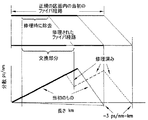
図15を参照すると、全数N−Pケーブル修理の筋書きに関する損失と理想的LBO値の計算がさらに詳細に述べられている。図15は、修理リピータ・スプライス・ボックス(LBO付き)52a、52bの挿入を伴ったスプライスを含む完了した全数N−P修理を示している。範例の実施形態では、LBOはLMFファイバを使用して作製されている。LとRはそれぞれ左側と右側で当初のケーブル区画の残りの長さ(km)を表わす。当初のケーブルから交換部分への両方の接続(左と右)が全数N−Pケーブルであるのでこれが全数N−Pの修理であることに留意すべきである。ファイバ・スプライスの損失(dB)は次のように区別される、すなわちSp:PからPへのスプライス、Sn:NからNへのスプライス、Sn/p:N−PまたはP−Nのスプライス、Sp/L:PからLMFファイバへのスプライス、Sn/L:NからLMFファイバへのスプライス、およびBn/p:間にブリッジ・ファイバを入れた当初のファイバの工場のスプライス(スプライス損失値は直接の船上N−PスプライスSn/pと異なる)である。LBO端部のスプライス損失以外のLBO損失がないと仮定すると、修理されたケーブル区画の損失は次の通りであり、
東向き:[Lpeαp+Ypeαp+Yneαn+(3Sp+Sn/p+2Sn/L+2Sp/L+Bpn)+Rpeαp+Rneαn]dB 式8
西向き:[Lnwαn+Ynwαn+Ypwαp+(Sn+Sn/p+2Sp+2Sp/L+2Sn/L+Bpn)Rnwαn+Rpwαp]dB 式9
ここでαpとαnはPおよびNファイバの減衰度dB/kmであり、Lpe、Lnw、Rpe、Rne、RnwおよびRpwはそれぞれ左−東向きのPファイバ、左−西向きのNファイバ、右−東向きのPファイバ、右−東向きのNファイバ、右−西向きのNファイバおよび右−西向きのPファイバの長さ(km)である。
Referring to FIG. 15, the calculation of losses and ideal LBO values for the scenario of 100% NP cable repair is described in more detail. FIG. 15 shows a complete N-P repair completed including splices with the insertion of repair repeater splice boxes (with LBO) 52a, 52b. In an exemplary embodiment, the LBO is made using LMF fiber. L and R on the left and right respectively represent the remaining length (km) of the original cable section. It should be noted that this is a complete NP repair since both connections (left and right) from the original cable to the replacement section are all NP cables. Loss of the fiber splice (dB) are distinguished as follows, i.e. S p: splice from P to P, S n: the splice from N to N, S n / p: N -P or P-N of the splice, S p / L: splice from P to LMF fiber, S n / L: splice from N to LMF fiber, and B n / p: of the original fiber containing the bridge fiber between the factory of the splice (The splice loss value is different from the direct onboard NP splice Sn / p ). Assuming that there is no LBO loss other than the LBO end splice loss, the loss of the repaired cable section is:
Eastward: [L pe α p + Y pe α p + Y ne α n + (3S p + S n / p + 2S n / L + 2S p / L + B pn) + R pe α p + R ne α n] dB formula 8
West: [L nw α n + Y nw α n + Y pw α p + (S n + S n / p + 2S p + 2S p / L + 2S n / L + B pn) R nw α n + R pw α p] dB Formula 9
Here, α p and α n are the attenuation dB / km of the P and N fibers, and L pe , L nw , R pe , R ne , R nw and R pw are the left-east facing P fiber and the left − Length of west N fiber, right east P fiber, right east N fiber, right west N fiber and right west P fiber length (km).
修理リピータ50の入力部と出力部のLBO損失を計上すると、伝送の各々の方向で挿入される合計のLBO損失は、Bで規定される正規のケーブル区画の公称損失(ケーブル区画の公称バルク損失)の2倍から減算された式8と9から算出される損失に等しい。ケーブル区画のこの公称バルク損失はシステム毎に変わる可能性があり、一例では10.46dBである。スプライス・ボックス52a、52b内の左手および右手のLBO(LBOLとLBOR)の間でこの合計のLBO損失(LBOT)がどのように配分されるかは、修理リピータ50の両側の新たなケーブル区画の間の損失の差異を最小限にすることによって決定される可能性がある。
Taking into account the LBO loss at the input and output of the
LLとLRが2つの新たな区画、すなわち1つは修理リピータの左で1つは右の区画の損失を表わすとすると、理想的なLBO値は次のようになる。
LBOL=(B+LL)dB 式10
LBOR=(B−LR)dB 式11
Assuming that L L and L R represent the loss of two new partitions, one on the left of the repair repeater and one on the right, the ideal LBO value would be:
LBO L = (B + L L )
LBO R = (B- LR ) dB Equation 11
いくつかの修理では、式10または11のいずれかの値は負である可能性がある。これが生じると、負と算出するどのようなLBO損失も0に設定され、その他のLBOはLBOTの値をとる。このアルゴリズムは修理リピータ50の両側の新たなケーブル区画の間の損失の差異を最小限にし、2つの新たな区画の合計損失をケーブル区画の公称設計損失の2倍に等しく保つ。この同じアルゴリズムは、下記で述べるように正規と補償の両方の区画に関するすべての残りの修理筋書きにも当てはまる。
For some repairs, the value of either
混成の修理(図12参照)については、修理されたケーブル区画の損失(LBO損失を無視)は次のように計算される。
東向き:[Lpeαp+Ypeαp+Yneαn+(2Sp+Sn/p+2Sn/L+2Sp/L+Bp/n)+Rpeαp+Rneαn]dB 式12
西向き:[Lnwαn+Ynwαn+Ypwαp+(Sn+Sp+Sn/p+3Sp/L+2Sp/L−Bn/p+Sn/L)+Rpwαp]dB 式13
For a hybrid repair (see FIG. 12), the loss of the repaired cable section (ignoring the LBO loss) is calculated as follows.
Eastward: [L pe α p + Y pe α p + Y ne α n + (2S p + S n / p + 2S n / L + 2S p / L + B p / n) + R pe α p + R ne α n]
West: [L nw α n + Y nw α n + Y pw α p + (S n + S p + S n / p + 3S p / L + 2S p / L -B n / p + S n / L) + R pw α p] dB formula Thirteen
この修理の筋書きについては、損失の計算は工場でブリッジされたN−Pスプライスを計上し、それは西向き方向で除外される。
全数Pの修理(図13参照)については、修理されたケーブル区画の損失(LBO損失を無視)は次のように計算される。
東向き:[Lpeαp+Ypeαp+Yneαn+(2Sp+Sn/p+2Sn/L+Sp/L+Bn/p)+Rpeαp+Rneαn]dB 式14
西向き:[Lnwαn+Lpwαp+Ynwαn+Ypwαp+(Bn/p+2Sn/p+2Sp+3Sp/L+Sn/L)+Rpwαp]dB 式15
For this repair scenario, the loss calculation accounts for the NP splice bridged at the factory, which is excluded in the west direction.
For all P repairs (see FIG. 13), the repaired cable section loss (ignoring LBO loss) is calculated as follows:
Eastward: [L pe α p + Y pe α p + Y ne α n + (2S p + S n / p + 2S n / L + S p / L + B n / p) + R pe α p + R ne α n]
West: [L nw α n + L pw α p + Y nw α n + Y pw α p + (B n / p + 2S n / p + 2S p + 3S p / L + S n / L) + R pw α p] dB formula 15
これらの式は混成および全数N/Pの修理の匹敵するものとわずかに異なるが、その理由は当初のものと交換部分の間の界面である程度のスプライス損失が異なるせいである。
修理時に当初のP部分が完全に除去される(図14参照)と、修理されたケーブル区画の損失(LBO損失を無視)は次のように計算される。
東向き:[Lpeαp+Ypeαp+Yneαn+(2Sp+Sn/p+3Sn/L+2Sp/L)+Rneαn]dB 式16
西向き:[Lnwαn+Ynwαn+Ypwαp+(Sn+Sp+Sn/p+3Sp/L+Sn/L)+Rpwαp]dB 式17
These equations are slightly different from those of the hybrid and all N / P repairs, due to some differences in splice loss at the interface between the original and the replacement part.
When the original P portion is completely removed during repair (see FIG. 14), the repaired cable section loss (ignoring LBO loss) is calculated as follows.
Eastward: [L pe α p + Y pe α p + Y ne α n + (2S p + S n / p + 3S n / L + 2S p / L) + R ne α n]
West: [L nw α n + Y nw α n + Y pw α p + (S n + S p + S n / p + 3S p / L + S n / L) + R pw α p] dB formula 17
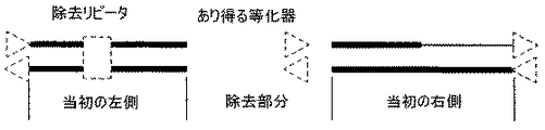
図16〜18を参照すると、すべての補償区画で生じ得る3通りの筋書きは次の通りである、すなわち(1)区画内に利得等化器なし(図16)、(2)修理時に回収されないが区画内に利得等化器存在(図17)、および(3)区画内に利得等化器存在でかつ修理時に回収(図18)である。利得等化器は隣り合うスプライス・ボックス内でLBOを付随する可能性がある。 Referring to FIGS. 16-18, the three scenarios that can occur in all compensation sections are: (1) no gain equalizer in the section (FIG. 16), (2) not recovered on repair Are the gain equalizers present in the compartment (FIG. 17), and (3) the gain equalizers are present in the compartment and are recovered at the time of repair (FIG. 18). Gain equalizers may have LBOs in adjacent splice boxes.
図19は、故障発生区画が利得等化器を含まないとき、スプライス・ボックス52a、52b内で修理リピータのLBOを付随するスプライスを含む、完了した補償ケーブル区画の修理を示している。修理された区画の損失は次のように計算される。
東向き:[Lpeαp+Ypeαp+Yneαn+2Sp+Sn/p+2Sn/L+2Sp/L+Rpeαp]dB 式18
西向き:[Lnwαn+Ynwαn+Ypwαp+(2Sn/p+Sp+3Sp/L+Sn/L)+Rpwαp]dB 式19
FIG. 19 illustrates the completed repair of the compensating cable section, including the splice that accompanies the LBO of the repair repeater in the
Eastward: [L pe α p + Y pe α p + Y ne α n + 2S p + S n / p + 2S n / L + 2S p / L + R pe α p] dB formula 18
West: [L nw α n + Y nw α n + Y pw α p + (2S n / p + S p + 3S p / L + S n / L) + R pw α p] dB formula 19
この範例は当初の区画に装着される利得等化器を含んでいないけれども、大きな値(たとえば4dB以上)のLBOが異なった全数−Pの補償ケーブル区画の中間付近にあることは可能である。修理時にこのLBOが回収されるならば、修理リピータが不要となることは可能である。ある修理方法によると、修理リピータの必要性を未然に防ぐために、たとえそれ以外に必要ではない場合でもそのようなLBOは回収される可能性がある。伝送の各方向に関する算出LBO値が公称リピータ利得のdB以内であるとき、リピータまたはLBOは不要である。 Although this example does not include a gain equalizer mounted in the original section, it is possible that a large value (eg, 4 dB or more) of LBO is in the middle of a different all-P compensating cable section. If this LBO is recovered at the time of repair, it is possible that the repair repeater is not required. According to one repair method, such LBOs may be recovered even if not otherwise necessary, to obviate the need for a repair repeater. When the calculated LBO value for each direction of transmission is within dB of the nominal repeater gain, no repeater or LBO is required.
回収されない利得等化器を含む修理された補償ケーブル区画で、上記の利得等化器のないケースとの違いは、当初の区画の右手部分に等化器の有効平坦損失(隣り合うスプライス・ボックスのLBOに付随する可能性がある)が加えられる必要性があることである。下記の式で、等化器損失はEdBで表わされ、それは同様に利得等化器損失、等化器と隣り合うスプライス・ボックス内のいかなる追加の工場装備のLBOも含む。修理されたケーブル区画の損失は次のように計算される。
東向き:[Lpeαp+Ypeαp+Yneαn+(2Sp+Sn/p+2Sn/L+2Sp/L)+Rpeαp+E]dB 式20
西向き:[Lnwαn+Ynwαn+Ypwαp+(2Sn/p+Sp+3Sp/L+Sn/L)+Rpwαp+E]dB 式21
The difference between the repaired compensating cable section containing the unrecovered gain equalizer and the case without the gain equalizer described above is that the effective flat loss of the equalizer (adjacent splice box) (Which may be associated with the LBO). In the equation below, the equalizer loss is expressed in dB, which also includes the gain equalizer loss and any additional factory-installed LBO in the splice box adjacent to the equalizer. The repaired cable section loss is calculated as follows:
Eastward: [L pe α p + Y pe α p + Y ne α n + (2S p + S n / p + 2S n / L + 2S p / L) + R pe α p + E]
West: [L nw α n + Y nw α n + Y pw α p + (2S n / p + S p + 3S p / L + S n / L) + R pw α p + E] dB formula 21
図20は、利得等化器が回収され、かつ修理リピータLBOの挿入に付随するスプライスを含めて交換されるときの完了した補償ケーブル区画の修理を示している。故障発生ケーブル中で利得等化器が回収されるならば、修理の交換用ケーブル部分は除去された等化器のための交換用等化器ユニット60を含む。交換用等化器ユニット60は予備のユニットか、または、まだ使用可能であるという前提で、回収した等化器(しかしいかなる隣接LBOも付随しない)のいずれかである可能性がある。スプライス損失を最小限にするために、交換用等化器ユニット60は交換用ケーブル部分の全数−P長さ34内でシステムに接続される必要がある。この修理では、修理を完了するために(通常の5個に代わって)7個のスプライス・ボックスが使用される。修理された区画の損失は次のように計算される。
東向き:[Lpeαp+Ypeαp+Yenαn+E+(4Sp+Sn/p+2Sn/L+2Sp/L)+Rpeαp]dB 式22
西向き:[Lnwαn+Ynwαn+Ypwαp+(2Sn/p+3Sp+3Sp/L+Sn/L)+E+Rpwαp]dB 式23
FIG. 20 illustrates the completed repair of the compensating cable section when the gain equalizer is recovered and replaced, including the splice associated with the insertion of the repair repeater LBO. If the gain equalizer is recovered in the failed cable, the replacement cable portion of the repair includes a
Eastward: [L pe α p + Y pe α p + Y en α n + E + (4S p + S n / p + 2S n / L + 2S p / L) + R pe α p] dB formula 22
West: [L nw α n + Y nw α n + Y pw α p + (2S n / p + 3S p + 3S p / L + S n / L) + E + R pw α p] dB formula 23
LBO値の実際の計算はいくつかのケースではさらに複雑である可能性があり、したがって上の式は変えられる可能性がある。たとえば、LBOが挿入されるときにはLBOの各々の端部に追加のスプライス損失(たとえばSp/L)が存在し、前に示した損失の式、すなわち式8と9、および式12から23にこれらのスプライス損失を含ませることによってこれが計上された。しかしながら、もしも修理リピータの一方の端部でLBOが必要とされないならば、普通2つのLBO端部スプライス(たとえば2Sp/L)によって供給される損失はもはや両方ではなく、修理リピータの後部でケーブルからケーブルへの直接スプライスが存在する。この状況では、修理リピータの他方の側のLBOの値は結果的に生じるスプライス損失の差異を計上することが好ましい。計算の他の変形例によると、式10または11を使用するLBO損失の計算がLBO挿入に対応する端部スプライス損失よりも小さい場合、LBO損失はゼロに設定されることが可能である。
The actual calculation of the LBO value may be more complicated in some cases, and thus the above equation may be changed. For example, when an LBO is inserted, there is an additional splice loss (eg, Sp / L ) at each end of the LBO, and the loss equations given earlier, ie, Equations 8 and 9, and Equations 12-23, This was accounted for by including these splice losses. However, if LBO is not required at one end of the repair repeater, the losses typically provided by two LBO end splices (eg, 2Sp / L ) are no longer both, and cable There is a direct splice from the cable to the cable. In this situation, the value of LBO on the other side of the repair repeater preferably accounts for the resulting splice loss difference. According to another variation of the calculation, the LBO loss can be set to zero if the calculation of the LBO
故障の疑いのある場所に基づいて、最新の海底ケーブル・システム修理業務と同様にして最初のケーブル切断場所が選択される。好ましい方法では、最終的な湾曲部に修理リピータを有することを避けるために、切断部の左側と予測される方でケーブルが回収される。ケーブルはまた、環境に応じて右側で回収されることも可能である。その後、ケーブルに故障がないかどうか判定するためにケーブルが検査される。もしもなければ、故障が発見されて除去されるまで追加のケーブルが回収される。その後、この残りのケーブル区画の端部がブイで浮かべられる。 Based on the suspected failure location, the first cable disconnection location is selected, similar to modern submarine cable system repair operations. In the preferred method, the cable is recovered on the expected side to the left of the cut to avoid having a repair repeater in the final bend. Cables can also be collected on the right depending on the environment. Thereafter, the cable is inspected to determine if the cable is faulty. If not, additional cable is collected until the fault is found and eliminated. The end of the remaining cable section is then floated with a buoy.
その後、他方のケーブルが回収され、ケーブルに故障がないかどうか判定するために回収されたケーブルが検査される。もしもなければ、故障が発見されて除去されるまで追加のケーブルが回収される可能性がある。いかに多くのケーブルが切断部の両側から回収されるかによって、左側が低い方の損失を備えた方であることを確実化するために左と右の初期の指定が逆転される必要が生じる可能性がある。 Thereafter, the other cable is retrieved and the retrieved cable is inspected to determine if the cable is faulty. If not, additional cables may be retrieved until the fault is found and eliminated. Depending on how much cable is recovered from both sides of the cut, the initial designation of left and right may need to be reversed to ensure that the left side has the lower loss There is.
この時点で、除去される当初のケーブルの長さ、左側と右側で残る当初のケーブルの長さ、および修理現場の水深が判定可能である。必要であれば、光学式の時間域反射計(OTDR)の読みを使用してこれらの長さを判定することも可能である。OTDRはNとPのファイバが一体にスプライスされている場所を識別することが可能である。これらの値に基づいて、修理に必要とされる余分のケーブルの量が決定される(たとえば水深の約2.5倍)。 At this point, the original cable length to be removed, the original cable length remaining on the left and right sides, and the water depth at the repair site can be determined. If necessary, these lengths can be determined using an optical time domain reflectometer (OTDR) reading. The OTDR can identify where the N and P fibers are spliced together. Based on these values, the amount of extra cable required for repair is determined (eg, about 2.5 times the water depth).
交換用ケーブル部分を構成する予備ケーブルの3つの部分の長さは、たとえば式4〜7を使用して算出される。修理リピータが使用される予定であるときは、修理リピータの左側と右側に関する理想的なLBO値もやはり、たとえば式8〜23を使用して算出される。算出した理想的なLBO値に基づいて、入手可能なLBO群からLBOが選択される。 The lengths of the three portions of the spare cable that make up the replacement cable portion are calculated using, for example, equations 4-7. If a repair repeater is to be used, ideal LBO values for the left and right sides of the repair repeater are also calculated, for example, using Equations 8-23. Based on the calculated ideal LBO value, an LBO is selected from the available LBO group.
その後、スプライス・ボックス36a、36bを使用してN−P予備ケーブル長さ32a、32bをP予備ケーブル長さ34に接続することによって交換用ケーブル部分が作製される。必要であれば、スプライス・ボックス52aを使用して修理リピータ50が交換用ケーブル部分の右端部で接続される(図10参照)。修理が回収した利得等化器を含む全数Pの補償区画である場合、交換用ケーブル部分の全数−P長さの中に交換用利得等化器60が設置される(図20参照)。その後、スプライス・ボックスを使用して交換ケーブル部分が残りの当初のケーブル区画の右側端部に連結される。交換用ケーブル部分がブイに戻され、スプライス・ボックスを使用して残りの当初のケーブル区画の左側に最終連結部が作製される。
The replacement cable section is then made by connecting the NP
本方法の別の変形例によると、最終連結部は正規のケーブル区画のN−Pケーブル内にあり、最終連結部に接続されるN−P予備ケーブル長さ32aは正味の分散変化ゼロについて算出された長さよりも長くされることが好ましい。残りの当初のケーブル区画の左側の回収が計画通りに進むならば、N−P予備ケーブル長さ32aの余分の長さは最終連結部が作製される前に除去されることが可能である。しかしながら、さらに多くの残りの当初のケーブルを除去しなければならない場合(例えば回収時にブイが紛失されたかまたはケーブルが損傷を受けた場合)、算出された長さを供給し、かつ回収時に失われた残りの当初のN−Pケーブルの量を追加的に置き換えるために余分の長いN−P予備ケーブルが適切に切り取られる可能性がある。 According to another variant of the method, the final connection is in the NP cable of the regular cable section and the NP spare cable length 32a connected to the final connection is calculated for a net zero variance change. It is preferable that the length be longer than the set length. If recovery of the left side of the remaining original cable section proceeds as planned, the extra length of NP spare cable length 32a can be removed before the final connection is made. However, if more and more of the original cable must be removed (e.g., if the buoy is lost or the cable is damaged during recovery), the calculated length will be supplied and lost during recovery. Extra long NP spare cables may be properly trimmed to additionally replace the remaining amount of original NP cable.
本発明の修理方法はまた、ケーブルに接続されたリピータで故障が生じる場合に勾配整合型ケーブル・システムを修理するのに使用されることも可能である。このタイプの修理では、回収された故障発生リピータに置き換えるために交換用リピータが使用される。交換用リピータは、上述したような修理リピータの接続と同様の方式で交換用ケーブル部分の一方の端部に接続されることが可能である。 The repair method of the present invention can also be used to repair a gradient matched cable system in the event that a repeater connected to the cable fails. In this type of repair, a replacement repeater is used to replace the recovered faulty repeater. The replacement repeater can be connected to one end of the replacement cable portion in a manner similar to the connection of a repair repeater as described above.
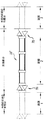
図21に示したような交換用ケーブル部分30”の一実施形態では、修理リピータ50が交換用ケーブル部分30の一方の端部に設置され、交換用リピータ70が他方の端部に設置される。交換用ケーブル部分はまた、修理リピータを備えないで交換用リピータを含むことも可能である。この好ましい実施形態では、修理リピータ50は当初の区画の左部分に接続され、そこでは損失は当初の区画の右部分のそれよりも少ない。LBO値は、ケーブル区画1とケーブル区画3の損失をそれらが修理される前にあったのと概ね同じに維持し、かつケーブル区画2の損失をケーブル区画損失の公称設計値に概ね等しく維持し、その結果システムの伝送スペクトルの端から端までの利得形状が修理による変化を名目上受けずに保たれることを確実化するように選択されることが好ましい。算出されたLBO損失値のうちの1つまたは複数が負であるいくつかのケースでは、各々のファイバ経路に関する3つの区画の合計損失が、3つの区画の理想的合計損失に概して等しいことが好ましい。ある方法による、理想的LBO値を算出するための式が下記でさらに詳細に述べられる。
In one embodiment of the
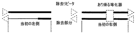
故障を生じたリピータを有するケーブル・システムを修理するとき、理想的なLBO値を計算するための式は修理の筋書きによって決まる。上記で検討した修理で、スプライス損失値がファイバ・タイプ依存性であるので、伝送の2つの方向すなわち左から右(「東向き」)と右から左(「西向き」)について別々の式が導き出される。4つのリピータ交換の修理の筋書きは除去されるリピータの両側にどのようなタイプのケーブル区画があるかによって決まると考えられる。図22〜25を参照すると、4つのリピータ交換の修理の筋書きは次の通りであり、すなわち(1)2つの正規のケーブル区画の間に配置されたリピータの除去(図22)、(2)2つの補償ケーブル区画の間に配置されたリピータの除去(図23)、(3)左に正規の区画を備え、右に補償区画を備えたリピータの除去(図24)、および(4)左に補償ケーブル区画を備え、右に正規のケーブル区画を備えたリピータの除去(図25)である。下記に述べられる損失の計算は、正規の区画から除去されるケーブル・タイプだけがN−Pケーブルであるという仮定、および補償区画内の等化器を回収する必要がないという仮定に基づいている。しかしながら、これは本発明の制限であるとは考えられない。 When repairing a cable system with a failed repeater, the formula for calculating the ideal LBO value depends on the repair scenario. In the repairs discussed above, since splice loss values are fiber type dependent, separate equations have been derived for the two directions of transmission: left-to-right ("eastward") and right-to-left ("westward"). It is. The repair scenario for a four repeater replacement will depend on what type of cable section is on each side of the repeater being removed. Referring to Figures 22-25, the repair scenario for four repeater replacements is as follows: (1) removal of repeaters located between two regular cable sections (Figure 22), (2). Elimination of the repeater located between the two compensation cable sections (FIG. 23), (3) Elimination of the repeater with the regular section on the left and compensation section on the right (FIG. 24), and (4) left Is a repeater with a compensating cable section and a regular cable section on the right (FIG. 25). The loss calculations described below are based on the assumption that the only cable type removed from the legitimate section is NP cable, and that there is no need to recover the equalizer in the compensation section. . However, this is not considered a limitation of the present invention.
図26を参照すると、筋書き3について損失と理想的LBO値の計算がさらに詳細に述べられている。図26は、交換用リピータ70と修理リピータ50に付随する交換部分内のLBOの挿入に伴うスプライスを含み、残りの当初の左部分に分かっているスプライス損失を含む、完了したリピータ交換の修理を示している。ファイバのスプライス損失(dB)は上記で規定される。
Referring to FIG. 26, the calculation of loss and ideal LBO value for
LBO損失がない(しかしLBOを導入するために必要な2つのスプライス損失を含む)ことを仮定すると、修理された区画の損失は次のように計算される。
東向き:[Lpeαp+Lneαn+Ypeαp+Yneαn+(2Sp+Bn/p+Sn/p+2Sn/L+4Sp/L+Sn)+Rpeαp+ER]dB 式24
西向き:[Lnwαn+Lpwαp+Ynwαn+Ypwαp+(Bn/p+Sn+Sn/p+2Sp+5Sp/LSn/L)+Rpwαp+ER]dB 式25
Assuming no LBO loss (but including the two splice losses required to introduce LBO), the repaired partition loss is calculated as follows:
Eastward: [L pe α p + L ne α n + Y pe α p + Y ne α n + (2S p + B n / p + S n / p + 2S n / L + 4S p / L + S n) + R pe α p + E R] dB Equation 24
West: [L nw α n + L pw α p + Y nw α n + Y pw α p + (B n / p + S n + S n / p + 2S p + 5S p / L S n / L) + R pw α p + E R] dB Equation 25
ここでαpとαnはPおよびNのファイバの減衰度dB/kmであり、ERは等化器(GEJまたはSCU)または中間区画のLBOのいずれか一方が補償区画にある場合のこれらの等価平坦損失を表わし、Lpe、Lne、Lnw、Lpw、RpeおよびRpwはそれぞれ左−東向き−P、左−東向き−N、左−西向き−N、左−西向き−P、右−東向き−P、および右−西向き−Pのファイバ経路の長さ(km)である。 Here alpha p and alpha n is the attenuation of dB / miles of fiber P and N, E R these if either one equalizer (GEJ or SCU) or intermediate compartment LBO is the compensation section Where L pe , L ne , L nw , L pw , R pe and R pw are left-eastward-P, left-eastward-N, left-westward-N, left-westward-, respectively. P, right-eastward-P, and right-westward-P fiber path lengths (km).
交換されたリピータが両側に補償区画を有する筋書き2の修理(図23参照)については、3つの新たな区画に関する修理後の損失(LBO損失を無視)は次のように計算されることが可能である。
東向き:[Lpeαp+EL+Ypeαp+Yneαn+(Sp+Sn/p+Sn/L+5Sp/L)+Rpeαp+ER]dB 式26
西向き:[Lnwαn+EL+Ynwαn+Ypwαp+(Sp+Sn/p+Sn/L+5Sp/L)+Rpwαp+ER]dB 式27
For the repair of
Eastward: [L pe α p + E L + Y pe α p + Y ne α n + (S p + S n / p + S n / L + 5S p / L) + R pe α p + E R] dB formula 26
West: [L nw α n + E L + Y nw α n + Y pw α p + (S p + S n / p + S n / L + 5S p / L) + R pw α p + E R] dB formula 27
ここでELとERは等化器または左もしくは右の中間区画LBOがいずれかの補償区画に配置された場合のこれらの等価平坦損失を計上する。
交換されたリピータが両側に正規のケーブル区画を有する筋書き1(図22参照)については、3つの新たな区画に関する修理後の損失(LBO損失を無視)は次のように計算される。
東向き:[Lpeαp+Lneαn+Ypeαp+Yneαn+(3Sp+Sn/p+2Sn/L+4Sp/L+2Bn/p+Sn)+Rpeαp+Rneαn]dB 式28
西向き:[Lnwαn+Lpwαp+Ynwαn+Ypwαp+(3Sp+Sn/p+4Sp/L+2Sn/L+2Bn/p+Sn)+Rpwαp+Rnwαn]dB 式29
Here E L and E R account for their equivalent flat loss when the equalizer or left or right middle section LBO is located in either compensation section.
For scenario 1 (see FIG. 22) in which the replaced repeater has regular cable sections on both sides, the post-repair losses (ignoring LBO losses) for the three new sections are calculated as follows.
Eastward: [L pe α p + L ne α n + Y pe α p + Y ne α n + (3S p + S n / p + 2S n / L + 4S p / L + 2B n / p + S n) + R pe α p + R ne α n ] dB Equation 28
West: [L nw α n + L pw α p + Y nw α n + Y pw α p + (3S p + S n / p + 4S p / L + 2S n / L + 2B n / p + S n) + R pw α p + R nw α n ] DB Equation 29
除去されたリピータが左に補償区画を有し、右に正規の区画を有する筋書き4の修理(図25参照)については、3つの新たな区画に関する修理後の損失(LBO損失を無視)は次のように計算される。
東向き:[Lpeαp+EL+Ypeαp+Yneαn+(Sn/p+2Sp+Sn/L+5Sp/L+Sn+Bn/p)+Rpeαp+Rneαn]dB 式30
西向き:[Lpwαp+EL+Ynwαn+Ypwαp+(2Sp+Sn/p+Sn+4Sp/L+2Sn/L+Bn/p)+Rpwαp+Rnwαn]dB 式31
For repair of scenario 4 where the removed repeater has a compensating section on the left and a regular section on the right (see FIG. 25), the post-repair losses (ignoring LBO losses) for the three new sections are: It is calculated as follows.
Eastward: [L pe α p + E L + Y pe α p + Y ne α n + (S n / p + 2S p + S n / L + 5S p / L + S n + B n / p) + R pe α p + R ne α n]
West: [L pw α p + E L + Y nw α n + Y pw α p + (2S p + S n / p + S n + 4S p / L + 2S n / L + B n / p) + R pw α p + R nw α n] dB Equation 31
範例の実施形態では、2つの追加リピータの各々について判定されるべき3つのLBO値が存在する。LBO値は、3つの新たなケーブル区画内の各々の経路の正味の損失を公称のケーブル区画損失に等しく保つように選択されることが好ましい。しかしながら補償区画については、補償区画によって供給される等化機能が理由となって、これらの区画を当初の区画の損失値に付け足すことが好ましい。計算が負のLBO値を結果的に生じさせる場合では、LBOはゼロに設定され、同じ経路と方向にある別のLBO値が、3つの新たなケーブル区画に関する正味の損失が3つの区画の望ましい損失の合計となるように再調整される可能性がある。もしもLBO値がゼロであり、かつLBOが挿入されないならば、正確なLBO値の判定にLBOの挿入に伴うスプライス損失の排除と1つの直接スプライスの追加が計上されることが好ましい。上記の式と計算は本発明の一実施形態に関する範例であり、本発明を実施するために他の式と計算が使用されることは可能である。 In an exemplary embodiment, there are three LBO values to be determined for each of the two additional repeaters. The LBO value is preferably selected to keep the net loss of each path in the three new cable sections equal to the nominal cable section loss. However, for the compensating sections, it is preferable to add these sections to the original section's loss value because of the equalization function provided by the compensating section. If the calculation would result in a negative LBO value, the LBO would be set to zero and another LBO value in the same path and direction would result in a net loss of 3 new cable sections for 3 sections. May be readjusted to total loss. If the LBO value is zero and no LBO is inserted, the determination of the correct LBO value preferably includes the elimination of the splice loss associated with the LBO insertion and the addition of one direct splice. The above formulas and calculations are exemplary for one embodiment of the present invention, and other formulas and calculations can be used to implement the present invention.
故障を生じたリピータを有するケーブル・システムを修理する方法では、交換用ケーブル部分に使用される予備ケーブルの長さは、概して、上述したような故障をもつケーブル・システムを修理するのと同じ方式で計算される。また、当初のケーブルを切断して交換用ケーブル部分を接続する工程も、概して、上述の修理方法と同じである。 In a method of repairing a cable system having a failed repeater, the length of the spare cable used for the replacement cable section is generally the same as for repairing a failed cable system as described above. Is calculated by Also, the process of cutting the original cable and connecting the replacement cable portion is generally the same as the repair method described above.
要約すると、本発明による、勾配整合型ケーブル・システムの修理の方法は、たとえ補償ケーブル区画で修理が為されるときでも修理の後の正味の端から端までのシステムの分散を両方の伝送方向で名目上不変に保つことを可能にし、新たに作製されたケーブル区画でシステムの伝送スペクトルの端から端までの利得形状が名目上不変となるように損失を確立する。
当業者による変更および代用は、添付の特許請求項による以外に制限されることのない本発明の範囲内に入ると考えられる。
In summary, the method of repairing a gradient-matched cable system according to the present invention reduces the net distribution of the system after the repair in both transmission directions, even when the repair is made in a compensating cable section. To establish the loss such that the gain profile across the transmission spectrum of the system is nominally unchanged in the newly created cable section.
Modifications and substitutions by one of ordinary skill in the art are considered to be within the scope of the invention without limitation, except as by the appended claims.
10:勾配整合ケーブル区画
12:P型ファイバ
14:N型ファイバ
16:中央部分
18a,18b:両端部分
20:ケーブル
30:交換用ケーブル部分
30’:交換用ケーブル部分
30”:交換用ケーブル部分
32a:第1のN−Pケーブル長さ
32b:第2のN−Pケーブル長さ
34:Pケーブル長さ
36a,36b:スプライス・ボックス
40:N型ファイバ群
42:P型ファイバ群
50:修理リピータ
52a,52b:スプライス・ボックス
60:交換用等価器ユニット
70:交換用リピータ
72a,72b:スプライス・ボックス
10: gradient matching cable section 12: P-type fiber 14: N-type fiber 16:
Claims (29)
前記勾配整合型ケーブル・システムの故障を生じた部分を除去する工程、
少なくとも1本のN型ファイバと少なくとも1本のP型ファイバを含む予備のN−Pケーブルから第1と第2のN−Pケーブル長さを供給する工程、
少なくとも第1と第2のP型ファイバを含む予備のPケーブルから少なくとも1本の全数−Pケーブル長さを供給する工程、
前記N−Pケーブル長さと前記Pケーブル長さから交換用ケーブル部分を作製し、そこでは前記N−Pケーブル長さが前記Pケーブル長さの両側に接続される工程、および
前記勾配整合型ケーブル・システムの端部間であって故障を生じた部分が除去された場所に前記交換用ケーブル部分を接続する工程を含む方法。 A method of repairing a gradient matched cable system including at least one N-type fiber having a negative dispersion and at least one P-type fiber having a positive dispersion,
Removing a failed portion of the gradient matched cable system;
Providing first and second NP cable lengths from a spare NP cable including at least one N-type fiber and at least one P-type fiber;
Providing at least one all-P cable length from a spare P cable including at least first and second P-type fibers;
Making a replacement cable portion from the NP cable length and the P cable length, wherein the NP cable length is connected to both sides of the P cable length; and the gradient matched cable. Connecting the replacement cable portion between the ends of the system where the failed portion has been removed.
前記第1のN−Pケーブル長さ内の前記N型ファイバ群を前記Pケーブル長さ内の前記P型ファイバ群の第1の半数にスプライスする工程、
前記第2のN−Pケーブル長さ内の前記N型ファイバ群を前記Pケーブル長さ内の前記P型ファイバ群の前記第1の半数にスプライスする工程、
前記第1のN−Pケーブル長さ内の前記P型ファイバ群を前記Pケーブル長さ内の前記P型ファイバ群の第2の半数にスプライスする工程、および
前記第2のN−Pケーブル長さ内の前記P型ファイバ群を前記Pケーブル長さ内の前記P型ファイバ群の第2の半数にスプライスする工程を含む、請求項7に記載の方法。 The step of producing the replacement cable portion,
Splicing the group of N-type fibers within the first NP cable length to a first half of the group of P-type fibers within the P cable length;
Splicing the group of N-type fibers within the length of the second NP cable to the first half of the group of P-type fibers within the length of the P cable;
Splicing the group of P-type fibers within the length of the first NP cable to a second half of the group of P-type fibers within the length of the P cable; and the second NP cable length 8. The method of claim 7, comprising splicing the group of P-type fibers within a second half of the group of P-type fibers within the P cable length.
半数のN型ファイバ群と半数のP型ファイバ群を含んでなり、前記N型ファイバ群が負の分散率を有する、第1と第2のN−Pケーブル長さと、
全数−P型のファイバ群を含む少なくとも1本のPケーブルと、
前記第1のN−Pケーブル長さと前記Pケーブル長さを接続しており前記第1のN−Pケーブル長さ内の前記N型ファイバ群が前記Pケーブル長さ内の前記P型ファイバ群の第1の半数にスプライスされ、かつ前記第1のN−Pケーブル長さ内の前記P型ファイバ群が前記Pケーブル長さ内の前記P型ファイバ群の第2の半数にスプライスされている第1のスプライス・ボックスと、
前記第1のN−Pケーブル長さと前記Pケーブル長さを接続しており、前記第1のN−Pケーブル長さ内の前記N型ファイバ群が前記Pケーブル長さ内の前記P型ファイバ群の前記第1の半数にスプライスされ、かつ前記第1のN−Pケーブル長さ内の前記P型ファイバ群が前記Pケーブル長さ内の前記P型ファイバ群の前記第2の半数にスプライスされている第2のスプライス・ボックスとからなり、
前記第1と第2のN−Pケーブル長さおよび前記Pケーブル長さが、前記交換用ケーブル部分で修理されたときに前記勾配整合型ケーブル・システムの正味の分散が名目上不変を保つように選択される交換用ケーブル部分。 A replacement cable portion for use in a gradient matched cable system,
A first and a second NP cable length comprising half of the N-type fiber group and half of the P-type fiber group, wherein the N-type fiber group has a negative dispersion ratio;
At least one P cable including a group of all-P fibers;
Connecting the first NP cable length and the P cable length, wherein the N-type fiber group within the first NP cable length is the P-type fiber group within the P cable length And the P-type fibers in the first NP cable length are spliced to the second half of the P-type fibers in the P cable length. A first splice box;
Connecting the first NP cable length and the P cable length, wherein the N-type fiber group within the first NP cable length is the P-type fiber within the P cable length The first half of the group is spliced to the first half and the P-type fibers in the first NP cable length are spliced to the second half of the P-type fibers in the P cable length. And a second splice box,
The first and second NP cable lengths and the P cable length are such that the net distribution of the gradient matched cable system remains nominally unchanged when repaired at the replacement cable section. Replacement cable part to be selected.
Pケーブル長さの両側に第1と第2のN−Pケーブル長さを接続する工程において、前記N−Pケーブル長さが、負の分散率を有する半数のN型ファイバ群と正の分散率を有する半数のP型ファイバ群を含み、かつ前記Pケーブル長さが全数P型のファイバ群を含み、前記第1と第2のN−Pケーブル長さおよび前記Pケーブル長さが、前記交換用ケーブル部分で修理されたときに前記勾配整合型ケーブル・システムの正味の分散が名目上不変を保つように選択される工程と、
前記N−Pケーブル長さの一方にリピータを接続する工程とを含む方法。 A method of making a replacement cable portion for use in a gradient matched cable system, comprising:
In the step of connecting the first and second NP cable lengths on both sides of the P cable length, the NP cable length is set such that the half of the N-type fiber group having a negative dispersion ratio and the positive dispersion The P-cable length includes a P-type fiber group, and the first and second NP cable lengths and the P-cable length are the same. Selecting the net dispersion of the gradient matched cable system to remain nominally unchanged when repaired at a replacement cable section;
Connecting a repeater to one of said NP cable lengths.
29. The method of claim 28, wherein the repeater is selected such that the gain shape across the transmission spectrum of the system is not nominally altered by repair.
Applications Claiming Priority (1)
| Application Number | Priority Date | Filing Date | Title |
|---|---|---|---|
| US10/364,230 US6782174B1 (en) | 2003-02-11 | 2003-02-11 | Method of repairing a slope-matched cable system and replacement cable portion for use therein |
Publications (2)
| Publication Number | Publication Date |
|---|---|
| JP2004246359A true JP2004246359A (en) | 2004-09-02 |
| JP2004246359A5 JP2004246359A5 (en) | 2005-10-06 |
Family
ID=32681688
Family Applications (1)
| Application Number | Title | Priority Date | Filing Date |
|---|---|---|---|
| JP2004033114A Pending JP2004246359A (en) | 2003-02-11 | 2004-02-10 | Method for repairing gradient-matched cable system and cable part for replacement used for same |
Country Status (4)
| Country | Link |
|---|---|
| US (1) | US6782174B1 (en) |
| EP (1) | EP1447697A3 (en) |
| JP (1) | JP2004246359A (en) |
| CA (1) | CA2455368C (en) |
Cited By (1)
| Publication number | Priority date | Publication date | Assignee | Title |
|---|---|---|---|---|
| JP2009526441A (en) * | 2006-02-03 | 2009-07-16 | タイコ テレコミュニケーションズ (ユーエス) インコーポレーテッド | Gain tilt control in optical amplification transmission systems |
Families Citing this family (3)
| Publication number | Priority date | Publication date | Assignee | Title |
|---|---|---|---|---|
| JP2003337268A (en) * | 2002-05-20 | 2003-11-28 | Nec Corp | Method of repairing optical cable and repair cable piece used for the same |
| US7058268B2 (en) * | 2003-08-07 | 2006-06-06 | Tyco Telecommunications (Us) Inc. | Deployable optical fiber transmission lines, optical transmission cable, and method of making same |
| US11480496B2 (en) * | 2018-12-19 | 2022-10-25 | Exfo Inc. | Test method for characterizing an optical fiber link |
Family Cites Families (23)
| Publication number | Priority date | Publication date | Assignee | Title |
|---|---|---|---|---|
| US5894537A (en) * | 1996-01-11 | 1999-04-13 | Corning Incorporated | Dispersion managed optical waveguide |
| US6137604A (en) * | 1996-12-04 | 2000-10-24 | Tyco Submarine Systems, Ltd. | Chromatic dispersion compensation in wavelength division multiplexed optical transmission systems |
| GB9706729D0 (en) * | 1997-04-03 | 1997-05-21 | Cable & Wireless Ltd | Method and apparatus for joining underwater cable |
| US6317238B1 (en) * | 1997-06-26 | 2001-11-13 | Tycom (Us) Inc. | Chromatic dispersion management for optical wavelength division multiplexed transmission systems |
| US6038356A (en) * | 1997-09-25 | 2000-03-14 | Tyco Submarine Systems Ltd. | Lightwave transmission system employing raman and rare-earth doped fiber amplification |
| US6320884B1 (en) * | 1998-02-26 | 2001-11-20 | Tycom (Us) Inc., | Wide bandwidth Raman amplifier employing a pump unit generating a plurality of wavelengths |
| US6307985B1 (en) * | 1998-07-10 | 2001-10-23 | Micro Therapeutics, Inc. | Optical transmission system |
| US6311002B1 (en) * | 1998-12-01 | 2001-10-30 | Tycom (Us) Inc. | Method and apparatus for reducing nonlinear penalties by proper arrangement of the dispersion map in an optical communication system |
| US6188823B1 (en) * | 1998-12-01 | 2001-02-13 | Tyco Submarine Systems Ltd. | Method and apparatus for providing dispersion and dispersion slope compensation in an optical communication system |
| AU745736B2 (en) * | 1998-12-03 | 2002-03-28 | Sumitomo Electric Industries, Ltd. | Dispersion equalization optical fiber and optical transmission line including the same |
| US6052219A (en) * | 1999-02-16 | 2000-04-18 | Tyco Submarine Systems Ltd. | Wide bandwidth Raman amplifier capable of employing pump energy spectrally overlapping the signal |
| JP2001174650A (en) * | 1999-12-15 | 2001-06-29 | Sumitomo Electric Ind Ltd | Optical fiber and optical cable |
| US6396624B1 (en) * | 2000-01-11 | 2002-05-28 | Tycom (Us) Inc. | Extended band erbium doped fiber amplifier |
| JP2001228336A (en) * | 2000-02-17 | 2001-08-24 | Fujitsu Ltd | Method for repairing transmissive section and optical communication system |
| EP1271193A4 (en) * | 2000-02-24 | 2005-07-06 | Sumitomo Electric Industries | Optical transmission line and optical transmission system including it |
| US6414786B1 (en) * | 2000-03-27 | 2002-07-02 | Tycom (Us) Inc. | Method and apparatus for reducing polarization dependent gain in Raman amplification |
| US6477306B2 (en) * | 2000-04-11 | 2002-11-05 | Sumitomo Electric Industries, Ltd. | Dispersion-compensating optical fiber, and, optical transmission line and dispersion-compensating module respectively including the same |
| US6424455B1 (en) * | 2000-10-03 | 2002-07-23 | Tycom (Us) Inc. | Wide bandwidth fiber raman amplifier |
| US6873798B1 (en) | 2000-11-03 | 2005-03-29 | Tyco Telecommunications (Us) Inc. | Method and apparatus for optimizing the dispersion and dispersion slope for a dispersion map with slope-compensating optical fibers |
| US6943935B2 (en) * | 2001-03-16 | 2005-09-13 | Corning Incorporated | Dispersion-managed cable for raman-assisted transmission |
| GB0112895D0 (en) * | 2001-05-26 | 2001-07-18 | Corning Cable Systems Ltd | Optical cables and methods of repairing damaged optical cable installations |
| JP2003337268A (en) * | 2002-05-20 | 2003-11-28 | Nec Corp | Method of repairing optical cable and repair cable piece used for the same |
| JP4304361B2 (en) * | 2002-05-29 | 2009-07-29 | 日本電気株式会社 | Optical transmission cable repair method |
-
2003
- 2003-02-11 US US10/364,230 patent/US6782174B1/en not_active Expired - Fee Related
-
2004
- 2004-01-16 CA CA2455368A patent/CA2455368C/en not_active Expired - Fee Related
- 2004-01-22 EP EP04250347A patent/EP1447697A3/en not_active Withdrawn
- 2004-02-10 JP JP2004033114A patent/JP2004246359A/en active Pending
Cited By (1)
| Publication number | Priority date | Publication date | Assignee | Title |
|---|---|---|---|---|
| JP2009526441A (en) * | 2006-02-03 | 2009-07-16 | タイコ テレコミュニケーションズ (ユーエス) インコーポレーテッド | Gain tilt control in optical amplification transmission systems |
Also Published As
| Publication number | Publication date |
|---|---|
| US20040156605A1 (en) | 2004-08-12 |
| EP1447697A3 (en) | 2004-12-29 |
| CA2455368A1 (en) | 2004-08-11 |
| CA2455368C (en) | 2010-11-02 |
| US6782174B1 (en) | 2004-08-24 |
| EP1447697A2 (en) | 2004-08-18 |
Similar Documents
| Publication | Publication Date | Title |
|---|---|---|
| CN103959717B (en) | Method and system for the fault recovery in branching type optical-fiber network | |
| US20060251423A1 (en) | Method and apparatus for identifying pump failures using an optical line interface | |
| CN108781114A (en) | Undersea optical communication network | |
| US20240039267A1 (en) | Submarine cable architecture with redundancy for facilitating shared landing site | |
| US7164864B2 (en) | Optical communications system and transmission section repair method | |
| JP2004246359A (en) | Method for repairing gradient-matched cable system and cable part for replacement used for same | |
| US5712936A (en) | Hybrid bi-directional three color wave division multiplexer and method using same | |
| US20090285584A1 (en) | Unrepeatered optical segment for use with repeatered series of optical segments | |
| JP4031409B2 (en) | Optical wavelength division multiplexing communication system | |
| EP1365269A2 (en) | Optical cable repair method and repair cable piece used therefore | |
| Bergano et al. | Submerged plant equipment | |
| JP4304361B2 (en) | Optical transmission cable repair method | |
| CN106464381A (en) | Multi-span optical communications link having remote optically pumped amplifier | |
| JP2005115133A (en) | Method for repairing submarine optical cable and cable determination method for repair | |
| Thomas et al. | Technology in undersea cable systems: 50 years of progress | |
| JP3411962B2 (en) | Submarine optical cable connection box | |
| Denniston et al. | The glass necklace [FLAG submarine fibre-optic link] | |
| JP2005073088A (en) | Dmf cable repair method | |
| Sarif et al. | Design and Analysis of Multi-Core Fiber with SDM (Space Division Multiplex) Technology in Singapore to Surabaya via Southern Sea of Java | |
| Letellier | Submarine systems: From laboratory to seabed | |
| EP1511201B1 (en) | Optical fiber transmission lines with dispersion management, optical transmission cable, and method of making same | |
| JP4894516B2 (en) | Optical transmission cable for optical communication, manufacturing method thereof, and optical communication transmission apparatus | |
| Fox et al. | Submarine optical fibre cable system applications | |
| Superhighway et al. | COST EFFECTIVE SUBMARINE FIBRE OPTIC SYSTEMS | |
| Ross | UNDERSEA LIGHTWAVE TRANSMISSION |
Legal Events
| Date | Code | Title | Description |
|---|---|---|---|
| A521 | Request for written amendment filed |
Free format text: JAPANESE INTERMEDIATE CODE: A523 Effective date: 20050809 |
|
| A621 | Written request for application examination |
Free format text: JAPANESE INTERMEDIATE CODE: A621 Effective date: 20050809 |
|
| A977 | Report on retrieval |
Free format text: JAPANESE INTERMEDIATE CODE: A971007 Effective date: 20060515 |
|
| A131 | Notification of reasons for refusal |
Free format text: JAPANESE INTERMEDIATE CODE: A131 Effective date: 20060531 |
|
| A02 | Decision of refusal |
Free format text: JAPANESE INTERMEDIATE CODE: A02 Effective date: 20061025 |