JP2004244865A - Joining structure of meter piping unit - Google Patents
Joining structure of meter piping unit Download PDFInfo
- Publication number
- JP2004244865A JP2004244865A JP2003034190A JP2003034190A JP2004244865A JP 2004244865 A JP2004244865 A JP 2004244865A JP 2003034190 A JP2003034190 A JP 2003034190A JP 2003034190 A JP2003034190 A JP 2003034190A JP 2004244865 A JP2004244865 A JP 2004244865A
- Authority
- JP
- Japan
- Prior art keywords
- pipe
- meter
- piping
- pipes
- unit
- Prior art date
- Legal status (The legal status is an assumption and is not a legal conclusion. Google has not performed a legal analysis and makes no representation as to the accuracy of the status listed.)
- Pending
Links
Images


Abstract
Description
【0001】
【発明の属する技術分野】
本発明は、例えば集合住宅において、各住戸への給水配管系統に接続する複数の計量メーターを交換可能にユニット化することが可能なメーター配管ユニットの結合構造に関するものである。
【0002】
【従来の技術】
一般に集合住宅において、各住戸内の給水配管設備は、共用部パイプシャフト内の給水立管から住戸毎にそれぞれ専用給水管を分岐して住戸内の各使用個所まで配管している。そして、各住戸の水道水使用量を水道局が計量するために、共用パイプシャフト内で、各専用給水管に水道局より貸与された水道メーターを設置している。
【0003】
近年、集合住宅における給水設備では、受水槽より給水ポンプで直接各使用個所へ水を供給するポンプ直送方式や、受水槽を設置せずに、水道本管より引き込んだ水道水を給水ポンプにより直接各使用個所へ供給する水道直結増圧方式が主流となってきている。
【0004】
上述のポンプ直送方式や水道直結増圧方式の給水設備の場合、供給ゾーン内での使用水量の増減による圧力変動が高置水槽方式に比べて大きく、また、両方式ともポンプからの直送給水のため、ポンプの制御機構が故障した場合、供給圧力が異常に上昇する恐れもある。そこで、給水している衛生器具に影響を与えないため、また、シャワー等での給水圧力変動による温度変化等を解消するために、共用パイプシャフト内の専用給水管に減圧弁を設置して、各住戸内に供給する給水圧力が一定圧力以上にならないようにしている。
【0005】
集合住宅では、一般に、パイプシャフトを2住戸分で共用し、そのパイプシャフト内に2住戸分の計量メーターおよびメーター廻り配管を設置する場合が多い。この場合のメーター廻りの配管構造を、給水立管分岐管以降から順番に説明すると、以下の通りである。
まず、給水立管より、分岐継手により給水横枝管を分岐する。さらに、給水横枝管を分岐継手により専用給水管2本に分岐する。そして、分岐後の専用給水管には、水道メーター交換時等に給水立管からの給水を遮断する止水弁(閉止弁)と給水圧力を一定圧力以下に保つための減圧弁を配置する。この場合、止水弁および減圧弁は、一定の向き(方向性一定)に固定した取付状態としている。減圧弁は、異物の流入による故障を防止するためのストレーナーを一次側に有しており、その減圧弁の二次側には水道メーターが接続配置される。この水道メーターは、故障時の交換可能な取付構造とするために、その一次側および二次側の端部には、袋ナットによる着脱自在な構造のメータ接続用ソケットが配置される。なお、メータ接続用ソケットは、交換する水道メーターが既存のものと大きさが異なる場合に対応させるために伸縮機能を有している。水道メーターの二次側の専用給水管には、水道メーター交換時に住戸内の専用給水管内滞留水が流出しないように逆流防止弁が設けられている。また、各弁類を接続する部分には、接続用ソケットや短管が随時挿入接続されるようになっている。そして、逆流防止弁以降の専用給水管は、そのまま住戸内まで配管して、住戸内で使用個所数に応じた分岐配管が行われる。また、共用パイプシャフト内に給湯器が設置されている場合、共用パイプシャフト内で、専用給水管から給湯器用の給水管を分岐することが多い。
【0006】
近年、現場施工の省力化や施工時間の短縮化、これらに伴う人件費の低減、そして、配管長のコンパクト化を図るために、止水弁から逆流防止弁までのメーター廻り配管のユニット化が既に実施され始めており、それなりの効果を上げている。
しかし、この場合のメーター配管ユニットは、1住戸分のユニットであり、さらなる現場作業の省略化、施工時間の短縮化、ローコスト化を進めるには、2住戸分のメーター廻り配管全体をユニット化することが本来最も望ましい。
【0007】
また中高層建築物の給湯設備には、機械室等に設置した貯湯槽やボイラから給湯水を循環ポンプと循環配管(給湯往管と給湯還管)により建物全館を循環させ、各階の共用パイプシャフト内で分岐して給湯水を使用個所に供給する中央式給湯方式がある。この方式を使用している集合住宅においては、共用パイプシャフト内で給湯立管(往管側)から給湯横枝管を分岐し、さらに各住戸の専用給湯管に分岐して、各専用給湯管に止水弁と減圧弁および給湯使用量計量のための計量メーターを設置している場合がある。
なお、この上記先行技術は当業者一般に知られた技術であって、文献公知発明に係るものではない。
【0008】
【発明が解決しようとする課題】
近年の集合住宅は、購入者のニーズを満たすために1棟内での住戸分間取りプランの種類が多くなってきている。それに伴い、共用パイプシャフト形状の種類も多くなってきている。その共用パイプシャフトは、点検扉から見て、縦長、横長等の形状があり、また、同じ形状であっても寸法が異なることも多い。また、集合住宅の共用パイプシャフトは、面積が狭く、メーター廻り配管の設置スペースに余裕がない。2住戸分一体のメーター配管ユニットを工場で製作しようとしても、1種類のユニットでは各共用パイプシャフトの形状に対応しきれない。結局、共用パイプシャフトの形状毎に設計しなければならなくなり、従来の施工方法よりも却ってトータルコストがかかってしまうという課題があった。
さらに、中央式給湯設備に使用する集合住宅においても、給水設備の場合と同様の理由による課題があった。
【0009】
本発明は上記のような課題を解決するためになされたもので、現場での配管施工を大幅に省力化でき、その配管施工時間の短期化および人件費の低減が図れるメーター配管ユニットの結合構造を提供することを目的とする。
【0010】
また、本発明は、従来の現場での配管施工よりも配管長をコンパクトにすることができ、狭いパイプシャフトスペースにも対応可能なメーター配管ユニットの結合構造を提供することを目的とする。
【0011】
さらに、本発明は、各住戸への専用給水管の接続方向の自由度が向上し、計量メーター廻り配管の二次側以降で、複数に分岐して給水または給湯する場合でも別途分岐継手を必要としないメーター配管ユニットの結合構造を提供することを目的とする。
【0012】
【課題を解決するための手段】
本発明に係るメーター配管ユニットの結合構造は、建物内の流体配管に接続する接続口を有する流入管に複数の分岐管を設け、該分岐管に閉止弁および減圧弁を配設して構成する分岐管ユニットと、前記分岐管に接続する接続口を一端に有し、他端に計量メーターに接続する接続口を有する中継配管、前記計量メーターに接続する接続口を一端に有し、他端に建物内の流体配管に接続する接続口を有し、かつ逆流防止弁を配設する逆流防止機能付配管、並びに前記中継配管および逆流防止機能付配管を積載する積載架台により構成するメーター配管ユニットとからなるメーター配管ユニットの結合構造において、前記中継配管を、前記分岐管と回動自在に接続したものである。
【0013】
本発明に係るメーター配管ユニットの結合構造において、逆流防止機能付配管は、建物内の流体配管に接続する接続口を複数有するものである。
【0014】
【発明の実施の形態】
以下、本発明の実施の一形態を説明する。
実施の形態1.
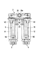
図1は本発明の実施の形態1によるメーター配管ユニットの結合構造を示す平面図、図2は図1の一部を断面した側面図、図3は図2の要部拡大断面図、図4図は図1のA−A線断面図、図5は計量メーター設置前のメーター配管ユニットの結合構造を示す側面図である。
図において、1はメーター配管ユニットである。このメーター配管ユニット1は、分岐管ユニット2および中継配管3,4ならびに逆流防止機能付配管5,6のそれぞれと、それらを積載する積載架台11,12とからなっており、その詳細な構成について以下に説明する。
【0015】
まず、分岐管ユニット2は、建物内の流体配管(例えば、集合住宅の共用パイプシャフト内に配管された給水立管から分岐した給水横枝管)に接続する接続口20aを有する流入管20と、この流入管20に一体形成した複数(図では2つ)の分岐管21,22と、これらの分岐管21,22のそれぞれに配設された閉止弁(止水弁)V1および減圧弁V2とから主要部が構成されている。なお、前記流入管20内には、分岐管21,22への異物の流入を阻止して閉止弁V1や減圧弁V2の故障を防止するためのストレーナー23が設けられている。
【0016】
また、前記分岐管21,22において、閉止弁V1の下流側に減圧弁V2が配設され、その減圧弁V2の取付部には、U字止めピンP1を外部から挿入するピン孔21a,22a(図では片方のピン孔21aのみを示す)が設けられ、これらのピン孔21a,22aから挿脱可能に挿入されたU字止めピンP1で減圧弁V2が取り付け固定されており、そのU字止めピンP1を引き抜くことで減圧弁V2を取り外すことができるようになっている。したがって、減圧弁V2のメンテナンスおよび交換を容易に行うことができる。
【0017】
さらに、前記分岐管21,22は、下向きの配管接続口21b,22bを有しており、これらの配管接続口21b,22bにエルボからなる前記中継配管3,4の一次側接続口がそれぞれ回動自在に接続されている。さらに詳しく述べると、中継配管3の一次側接続口の外周面には、図3に示すように、シールリング用溝部31が設けられ、この溝部31に取り付けたゴム製のシールリング32によって、中継配管3の一次側接続口と分岐管21の配管接続口21bとが水密に保たれている。
【0018】
また、分岐管ユニット2の片方の配管接続口21bにおける中継配管3との接続部にはU字止めピンP2を外部から挿入するためのピン孔(図示せず)が設けられ、かつ中継配管3の一次側外周面にはU字止めピン用溝部33が設けられており、このU字止めピン用溝部33に前記ピン孔からU字止めピンP2を打ち込むことにより、中継配管3の脱落防止を図っている。
【0019】
さらに、前記中継配管3の二次側管端部には、ゴム製のシールリング34と金属製のリング状ピンP3および袋ナットN1が設けられ、その袋ナットN1によって計量メーター7または代用管9(図5参照)の一次側が前記中継配管3の二次側に着脱自在に接続されるようになっている。
【0020】
以上は、分岐管ユニット2の一方の配管接続口21bと一方の中継配管3と一方の計量メーター7または代用管9との結合構造であるが、分岐管ユニット2の他方の配管接続口22bと他方の中継配管4と他方の計量メーター8または代用管10との結合構造も前記一方の結合構造と同様の構造となっているものである。
【0021】
積載架台11,12上において、前記中継配管3,4の二次側接続口との対向離間位置に逆流防止機能付配管5,6が搭載されており、その逆流防止機能付配管5,6の詳細構造について以下に説明する。
それらの逆流防止機能付配管5,6は、代用管9,10または計量メーター7,8を一端に有し、かつ他端に建物内の流体配管(計量メーター7,8からの給水を住戸内の使用個所まで導く配管)に接続する接続口を有するもので、それぞれの逆流防止機能付配管5,6は同一構造をなしているため、片方の逆流防止機能付配管5の詳細構造についてのみ説明する。
【0022】
すなわち、逆流防止機能付配管5は、図1〜図4に示すように、計量メーター7の二次側に接続する一次側接続管部51と、計量メーター7の二次側において住戸内の使用個所までの流体配管を接続するための複数(図では四方)の接続口52〜55とを有している。かかる逆流防止機能付配管5の内部において、その一次側接続管部51には逆流防止弁V3が配設されており、その逆流防止機能付配管5の一次側接続管部51には、二次側メータ接続管(直管)13を介して袋ナットN2により、代用管9または計量メーター7の二次側が着脱自在に接続されるようになっている。
【0023】
ここで、前記二次側メーター接続管13は、逆流防止機能付配管5の一次側接続口管部51に対して伸縮移動可能となっており、その伸縮調整によって計量メーター7の大きさに対応した長さに調整できるようになっている。なお、前記二次側メーターー接続管13は、一次側にゴム製のシールリング16と金属製のリング状ピンP4を有し、かつ二次側にシールリング用溝部14が設けられ、この溝部14に取り付けられたシールリング15を有している。
【0024】
以上のように構成されたメーター配管ユニット1は、図5に示すように、中継配管3,4の二次側と逆流防止機能付配管5,6の二次側接続管部13の一次側との間に代用管9,10を接続した後、中継配管3,4と逆流防止機能付配管5,6および代用管9,10と積載架台11,12との左右の配管ユニットを、前記中継配管3,4の一次側の前記配管接続部21b,22bとの接続部を中心として回動させることにより、図6に示すように前記左右の配管ユニットを平行方向に折り畳んだ状態で現場に納入される。
【0025】
現場では、折り畳み状態のメーター配管ユニット1をパイプシャフト内の定められた位置に設置した後、そのメーター配管ユニット1の前記左右の配管ユニットを図5に示すように開いて積載架台11,12が床面と固定されている。この状態において、分岐管ユニット2の流入管20の接続口20aが建物内の流体配管に袋ナット(図示せず)で接続されると共に、逆流防止機能付配管5,6の二次側接続口52〜55の少なくとも1つの接続口には、住戸内の使用個所に至る配管が接続される。また、二次側接続口52〜55のうち、配管を接続しないものに関しては、プラグ等で止水される。そして、水圧テスト、管内のフラッシング(清掃)が完了後、代用管9,10を取り外して、中継配管3,4の二次側と逆流防止機能付配管5,6の二次側メーター接続管13の一次側との間に計量メーター7,8が袋ナットN1,N2によって接続され、配管施工が終了する。
【0026】
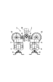
以上において、メーター配管ユニット1は、その左右の配管ユニットを図7および図8に示すように平行方向へ折り畳んだ状態でパイプシャフト内の所定位置に据え付け、この状態で計量メーター7,8を接続することも可能である。また、メーター配管ユニット1は、住戸内の使用個所に至る配管状況に応じて前記左右の配管ユニット(計量メーター7,8相互)の開き角度を調整して住戸内の使用個所に至る配管を接続することも可能である。
【0027】
【発明の効果】
以上のように、本発明によれば、建物内の流体配管に接続する接続口を有する流入管に複数の分岐管を設け、該分岐管に閉止弁および減圧弁を配設して構成する分岐管ユニットと、前記分岐管に接続する接続口を一端に有し、他端に計量メーターに接続する接続口を有する中継配管、前記計量メーターに接続する接続口を一端に有し、他端に建物内の流体配管に接続する接続口を有し、かつ逆流防止弁を配設する逆流防止機能付配管、並びに前記中継配管および逆流防止機能付配管を積載する積載架台により構成するメーター配管ユニットとからなるメーター配管ユニットの結合構造としたので、従来は現場で個々に配管施工しなければならなかった流入管、分岐継手、分岐管、減圧弁、閉止弁等を本発明では一体的にユニット化でき、このため、現場での配管施工を大幅に省力化でき、施工時間の短期化および人件費の低減が図れるという効果がある。また、前記ユニット化により、従来の現場での配管施工よりも配管長をコンパクト化でき、これまでよりも狭いパイプシャフトスペースにも対応可能になるという効果がある。
【0028】
特に、本発明によれば、分岐管と中継配管とを回動自在に接続するように構成したので、共用パイプシャフトの平面上での各メーター配管ユニット設置位置の自由度が向上するという効果がある。その結果、同じ仕様のメーター配管ユニット結合構造で多種のパイプシャフト形状に対応させることが可能になったという効果がある。このように、多種のパイプシャフト形状に対応できるため、工場で製作するメーター配管ユニット結合構造の仕様の種類を大幅に減少することができ、製作コストの低減を図ることが可能という効果がある。さらには、分岐管と中継配管とが回動自在な接続構造となっていることにより、メーター配管ユニットをコンパクトに折り畳んだ状態で在庫保管および現場への搬入を容易に行うことができるとともに、現場でのメンテナンスも容易になるという効果がある。
【0029】
また、本発明によれば、逆流防止機能付配管の二次側に複数の流体配管が接続可能な複数の接続口を有する構成としたので、専用給水管の接続方向の自由度が向上するという効果がある。また、逆流防止機能付配管の二次側以降に、複数に分岐して給水する場合でも別途分岐継手を用意する必要がないという効果がある。
【図面の簡単な説明】
【図1】この発明の実施の形態1によるメーター配管ユニットの結合構造を示す平面図である。
【図2】図1の一部を断面した側面図である。
【図3】図2の要部拡大断面図である。
【図4】図1のA−A線断面図である。
【図5】計量メーター設置前のメーター配管ユニットを示す側面図である。
【図6】図5のメーター配管ユニットを折り畳んだ状態を示す平面図である。
【図7】計量メーター設置後の図1のメーター配管ユニットを折り畳んだ状態を示す平面図である。
【図8】図7の正面図である。
【符号の説明】
1 メーター配管ユニット
2 分岐管ユニット
3,4 中継配管
5,6 逆流防止機能付配管
7,8 計量メーター
9,10 代用管
11,12 積載架台
13 二次側メータ接続管
14 シールリング用溝部
15,16 シールリング
20 流入管
20a 接続口
21,22 分岐管
21a,22a ピン孔
21b,22b 配管接続口
23 ストレーナー
31 シールリング用溝部
32 シールリング
33 U字止めピン用溝部
34 シールリング
51 一次側接続管部
52〜55 二次側接続口
N1,N2 袋ナット
P1,P2 U字止めピン
P3,P4 リング状ピン
V1 閉止弁
V2 減圧弁
V3 逆流防止弁[0001]
TECHNICAL FIELD OF THE INVENTION
The present invention relates to a combined structure of a meter piping unit that can replaceably replace a plurality of metering meters connected to a water supply piping system to each dwelling unit, for example, in an apartment house.
[0002]
[Prior art]
In general, in an apartment house, the water supply piping system in each dwelling unit branches a dedicated water supply pipe for each dwelling unit from a water supply standpipe in a common part pipe shaft, and pipes the pipe to each use point in the dwelling unit. Then, in order for the Water Bureau to measure the amount of tap water used in each dwelling unit, a water meter lent by the Water Bureau to each dedicated water supply pipe is installed in the common pipe shaft.
[0003]
In recent years, in water supply facilities in apartment houses, a water pump directly feeds water to each point of use by a water supply pump from a water receiving tank, or tap water drawn from a water main without using a water receiving tank. The mainstream is the water pressure boost system that supplies water to each point of use.
[0004]
In the case of the above-mentioned water supply equipment of the direct pumping system or the direct water supply booster system, the pressure fluctuation due to the increase or decrease of the amount of water used in the supply zone is larger than that of the high water tank system. Therefore, when the control mechanism of the pump breaks down, the supply pressure may increase abnormally. Therefore, in order not to affect the sanitary equipment that supplies water, and to eliminate temperature changes due to water supply pressure fluctuations in showers, etc., a pressure reducing valve is installed in a dedicated water supply pipe in the common pipe shaft, The supply pressure of water supplied to each dwelling unit is not to exceed a certain level.
[0005]
In an apartment house, in general, a pipe shaft is commonly used by two dwelling units, and a meter and a pipe around the meter for two dwelling units are often installed in the pipe shaft. The pipe structure around the meter in this case will be described below in order from the feed water branch pipe branch pipe.
First, a water supply horizontal branch pipe is branched from a water supply standing pipe by a branch joint. Further, the water supply horizontal branch pipe is branched into two dedicated water supply pipes by a branch joint. Then, in the dedicated water supply pipe after branching, a water stop valve (closing valve) for shutting off water supply from the water supply vertical pipe when replacing a water meter or the like and a pressure reducing valve for keeping the water supply pressure at a certain pressure or less are arranged. In this case, the water stop valve and the pressure reducing valve are in a fixed state in a fixed direction (constant direction). The pressure reducing valve has a strainer on the primary side for preventing a failure due to the inflow of foreign matter, and a water meter is connected to the secondary side of the pressure reducing valve. In order to make this water meter a replaceable mounting structure in the event of a failure, a meter connection socket having a detachable structure with a cap nut is arranged at the primary and secondary ends. The meter connection socket has a telescopic function in order to cope with a case where the replacement water meter is different in size from the existing one. The exclusive water supply pipe on the secondary side of the water meter is provided with a check valve to prevent the water remaining in the exclusive water supply pipe in the dwelling unit from flowing out when the water meter is replaced. Further, a connection socket and a short pipe are inserted and connected as needed at a portion where each valve is connected. Then, the dedicated water supply pipe after the check valve is directly piped to the inside of the dwelling unit, and branch pipes are formed in the dwelling unit according to the number of used places. When a water heater is installed in a common pipe shaft, a water pipe for a water heater is often branched from a dedicated water pipe in the common pipe shaft.
[0006]
In recent years, in order to save labor and shorten construction time for on-site construction, reduce labor costs associated with these and reduce the length of piping, unitization of meter piping from water stop valve to check valve has been implemented. It has already begun to be implemented, and it has produced a certain effect.
However, the meter piping unit in this case is a unit for one dwelling unit, and in order to further reduce the on-site work, shorten construction time, and reduce cost, unitize the entire meter piping for two dwelling units. It is originally most desirable.
[0007]
In the hot water supply facilities for middle- and high-rise buildings, hot water from hot water storage tanks and boilers installed in machine rooms and other facilities is circulated throughout the building using circulation pumps and circulation pipes (hot water supply pipes and hot water return pipes). There is a central hot water supply system that branches off inside and supplies hot water to the point of use. In a multiple dwelling house using this method, the hot water supply side pipe (outgoing pipe side) branches off the hot water supply horizontal branch pipe inside the shared pipe shaft, and further branches into the dedicated hot water supply pipe of each dwelling unit, and each dedicated hot water supply pipe In some cases, a water stop valve, a pressure reducing valve, and a meter for measuring the amount of hot water used are installed.
This prior art is a technique generally known to those skilled in the art, and does not relate to the invention disclosed in the literature.
[0008]
[Problems to be solved by the invention]
In recent years, in order to meet the needs of the purchaser, the number of types of housing separation plans within one building has increased in recent years. Accordingly, the types of common pipe shaft shapes have been increasing. When viewed from the inspection door, the common pipe shaft has a shape such as a vertically long shape and a horizontally long shape, and the dimensions are often different even if the shape is the same. In addition, the common pipe shaft of an apartment house has a small area, and there is not enough room for installing piping around the meter. Even if one attempts to produce a meter piping unit for two dwelling units in a factory, one type of unit cannot cope with the shape of each common pipe shaft. Eventually, it is necessary to design for each shape of the common pipe shaft, and there is a problem that the total cost is rather increased as compared with the conventional construction method.
Furthermore, there is a problem in the apartment house used for the central hot water supply system for the same reason as in the case of the water supply system.
[0009]
SUMMARY OF THE INVENTION The present invention has been made to solve the above-mentioned problems, and a piping structure of a meter piping unit can greatly reduce labor required for on-site piping work, thereby shortening the piping work time and reducing labor costs. The purpose is to provide.
[0010]
Another object of the present invention is to provide a connection structure of a meter piping unit that can make the piping length more compact than the conventional on-site piping work and can cope with a narrow pipe shaft space.
[0011]
Furthermore, the present invention improves the degree of freedom in the connection direction of the dedicated water supply pipe to each dwelling unit, and requires a separate branch joint even when branching and supplying water or hot water after the secondary side of the pipe around the metering meter. It is an object of the present invention to provide a connection structure of a meter piping unit that does not require a connection.
[0012]
[Means for Solving the Problems]
A connection structure of a meter piping unit according to the present invention is configured by providing a plurality of branch pipes in an inflow pipe having a connection port connected to a fluid pipe in a building, and disposing a closing valve and a pressure reducing valve in the branch pipe. A branch pipe unit, a relay pipe having a connection port connected to the branch pipe at one end and a connection port connected to a weighing meter at the other end, and a connection port connected to the weighing meter at one end; A piping unit having a connection port for connecting to a fluid pipe in a building and a check valve provided with a check valve, and a loading stand for mounting the relay pipe and the check valve. Wherein the relay pipe is rotatably connected to the branch pipe.
[0013]
In the connection structure of the meter piping unit according to the present invention, the piping with the backflow prevention function has a plurality of connection ports connected to the fluid piping in the building.
[0014]
BEST MODE FOR CARRYING OUT THE INVENTION
Hereinafter, an embodiment of the present invention will be described.
Embodiment 1 FIG.
FIG. 1 is a plan view showing a joint structure of a meter piping unit according to a first embodiment of the present invention, FIG. 2 is a side view in which a part of FIG. 1 is sectioned, FIG. The figure is a cross-sectional view taken along the line AA in FIG. 1, and FIG. 5 is a side view showing the connection structure of the meter piping unit before the installation of the metering meter.
In the figure, 1 is a meter piping unit. The meter piping unit 1 is composed of a
[0015]
First, the
[0016]
In the
[0017]
Further, the
[0018]
A pin hole (not shown) for inserting a U-shaped fixing pin P2 from the outside is provided at a connection portion between one of the
[0019]
Further, a
[0020]
The above is the connection structure of the one
[0021]
On the loading frames 11 and 12,
The
[0022]
That is, as shown in FIG. 1 to FIG. 4, the
[0023]
Here, the secondary-side
[0024]
As shown in FIG. 5, the meter piping unit 1 configured as described above is connected to the secondary side of the
[0025]
At the site, after installing the meter pipe unit 1 in a folded state at a predetermined position in the pipe shaft, the left and right pipe units of the meter pipe unit 1 are opened as shown in FIG. Fixed to the floor. In this state, the
[0026]
In the above, the meter piping unit 1 is installed at a predetermined position in the pipe shaft in a state where the left and right piping units are folded in the parallel direction as shown in FIGS. 7 and 8, and the
[0027]
【The invention's effect】
As described above, according to the present invention, a plurality of branch pipes are provided in an inflow pipe having a connection port connected to a fluid pipe in a building, and a closing valve and a pressure reducing valve are provided in the branch pipe. A pipe unit, a connection pipe connected to the branch pipe at one end, a relay pipe having a connection port connected to the weighing meter at the other end, a connection port connected to the weighing meter at one end, and a connection port at the other end. Having a connection port connected to a fluid pipe in the building, and a pipe with a backflow prevention function in which a check valve is disposed, and a meter pipe unit configured by a loading stand for loading the relay pipe and the pipe with a backflow prevention function; In the present invention, the inflow pipe, branch joint, branch pipe, pressure reducing valve, shutoff valve, etc., which had to be individually constructed on site at the site, are unitized in the present invention because the meter piping unit consists of Can this Because, the site can be labor-saving greatly installing the piping in, there is an effect that can be reduced in the short-term reduction and labor costs of construction time. Further, the unitization has an effect that the piping length can be made smaller than in the conventional on-site piping work, and it is possible to cope with a narrower pipe shaft space than before.
[0028]
In particular, according to the present invention, since the branch pipe and the relay pipe are configured to be rotatably connected, an effect that the degree of freedom in the installation position of each meter pipe unit on the plane of the shared pipe shaft is improved. is there. As a result, there is an effect that it is possible to cope with various types of pipe shaft shapes with a meter pipe unit coupling structure having the same specification. As described above, since it is possible to cope with various types of pipe shaft shapes, it is possible to greatly reduce the number of types of specifications of the meter piping unit connection structure manufactured at the factory, and it is possible to reduce the manufacturing cost. Furthermore, since the branch pipe and the relay pipe have a rotatable connection structure, inventory storage and transport to the site can be easily performed in a state where the meter piping unit is compactly folded. This also has the effect of making maintenance easier.
[0029]
Further, according to the present invention, since a plurality of connection ports to which a plurality of fluid pipes can be connected are provided on the secondary side of the pipe with the backflow prevention function, the degree of freedom in the connection direction of the dedicated water supply pipe is improved. effective. In addition, there is an effect that it is not necessary to separately prepare a branch joint even when water is branched into a plurality of portions after the secondary side of the pipe with the backflow prevention function.
[Brief description of the drawings]
FIG. 1 is a plan view showing a connection structure of a meter piping unit according to Embodiment 1 of the present invention.
FIG. 2 is a side view in which a part of FIG. 1 is sectioned.
FIG. 3 is an enlarged sectional view of a main part of FIG. 2;
FIG. 4 is a sectional view taken along line AA of FIG. 1;
FIG. 5 is a side view showing the meter piping unit before the installation of a weighing meter.
FIG. 6 is a plan view showing a state where the meter piping unit of FIG. 5 is folded.
FIG. 7 is a plan view showing a state in which the meter piping unit of FIG. 1 is folded after the meter is installed.
FIG. 8 is a front view of FIG. 7;
[Explanation of symbols]
DESCRIPTION OF SYMBOLS 1
Claims (2)
Priority Applications (1)
| Application Number | Priority Date | Filing Date | Title |
|---|---|---|---|
| JP2003034190A JP2004244865A (en) | 2003-02-12 | 2003-02-12 | Joining structure of meter piping unit |
Applications Claiming Priority (1)
| Application Number | Priority Date | Filing Date | Title |
|---|---|---|---|
| JP2003034190A JP2004244865A (en) | 2003-02-12 | 2003-02-12 | Joining structure of meter piping unit |
Publications (1)
| Publication Number | Publication Date |
|---|---|
| JP2004244865A true JP2004244865A (en) | 2004-09-02 |
Family
ID=33019949
Family Applications (1)
| Application Number | Title | Priority Date | Filing Date |
|---|---|---|---|
| JP2003034190A Pending JP2004244865A (en) | 2003-02-12 | 2003-02-12 | Joining structure of meter piping unit |
Country Status (1)
| Country | Link |
|---|---|
| JP (1) | JP2004244865A (en) |
Cited By (10)
| Publication number | Priority date | Publication date | Assignee | Title |
|---|---|---|---|---|
| JP2006133079A (en) * | 2004-11-05 | 2006-05-25 | Haseko Corp | Meter unit for water service or the like |
| JP2009293282A (en) * | 2008-06-05 | 2009-12-17 | Tabuchi Corp | Multiple meter unit |
| JP2011214394A (en) * | 2011-07-19 | 2011-10-27 | Tabuchi Corp | Multiple meter unit |
| JP2011214395A (en) * | 2011-07-19 | 2011-10-27 | Tabuchi Corp | Multiple meter unit |
| JP2011214393A (en) * | 2011-07-19 | 2011-10-27 | Tabuchi Corp | Multiple meter unit |
| JP2011231614A (en) * | 2011-07-19 | 2011-11-17 | Tabuchi Corp | Multiple meter unit |
| JP2011247085A (en) * | 2011-07-19 | 2011-12-08 | Tabuchi Corp | Multiple meter unit |
| JP2012132304A (en) * | 2012-01-17 | 2012-07-12 | Tabuchi Corp | Multiple meter unit |
| JP2016186493A (en) * | 2016-06-13 | 2016-10-27 | 株式会社タブチ | Duplex meter unit and frame for duplex meter unit |
| JP2017198700A (en) * | 2017-07-03 | 2017-11-02 | 株式会社タブチ | Duplex meter unit, and frame for the same |
-
2003
- 2003-02-12 JP JP2003034190A patent/JP2004244865A/en active Pending
Cited By (10)
| Publication number | Priority date | Publication date | Assignee | Title |
|---|---|---|---|---|
| JP2006133079A (en) * | 2004-11-05 | 2006-05-25 | Haseko Corp | Meter unit for water service or the like |
| JP2009293282A (en) * | 2008-06-05 | 2009-12-17 | Tabuchi Corp | Multiple meter unit |
| JP2011214394A (en) * | 2011-07-19 | 2011-10-27 | Tabuchi Corp | Multiple meter unit |
| JP2011214395A (en) * | 2011-07-19 | 2011-10-27 | Tabuchi Corp | Multiple meter unit |
| JP2011214393A (en) * | 2011-07-19 | 2011-10-27 | Tabuchi Corp | Multiple meter unit |
| JP2011231614A (en) * | 2011-07-19 | 2011-11-17 | Tabuchi Corp | Multiple meter unit |
| JP2011247085A (en) * | 2011-07-19 | 2011-12-08 | Tabuchi Corp | Multiple meter unit |
| JP2012132304A (en) * | 2012-01-17 | 2012-07-12 | Tabuchi Corp | Multiple meter unit |
| JP2016186493A (en) * | 2016-06-13 | 2016-10-27 | 株式会社タブチ | Duplex meter unit and frame for duplex meter unit |
| JP2017198700A (en) * | 2017-07-03 | 2017-11-02 | 株式会社タブチ | Duplex meter unit, and frame for the same |
Similar Documents
| Publication | Publication Date | Title |
|---|---|---|
| US6076608A (en) | Fire-suppression sprinkler system and method for installation and retrofit | |
| JP2004244865A (en) | Joining structure of meter piping unit | |
| JP2006308276A (en) | Circulation type hot water supply system | |
| JP2006207993A (en) | Sealed type hot water storage device | |
| JP6466490B2 (en) | Swivel with hydrant manifold for industrial fire fighting or swivel for hydrant manifold for industrial fire fighting | |
| CN111779069A (en) | Running water unit and running water system | |
| KR102363039B1 (en) | Fire-fighting pump package system | |
| DE202016100853U1 (en) | Flushing station for a ring or series piping system, loop system and piping system | |
| KR100643084B1 (en) | Piping system and the form of construction work of building | |
| KR100935550B1 (en) | Alarm valve assembly of sprinkler system with verification function | |
| CN212294825U (en) | Running water unit and running water system | |
| JP2004204481A (en) | Meter piping unit | |
| JP2001164606A (en) | Piping device of water supply device | |
| US20080163935A1 (en) | Auxiliary Water Supply for a Building | |
| CN205776482U (en) | A kind of house water system | |
| KR101872081B1 (en) | Water meter box equipment for house hold | |
| JP3425980B2 (en) | Pipe fitting for LP gas supply equipment | |
| JP2002070093A (en) | Method for installing integral pipe line for supplying water, draining, and supplying hot water | |
| KR100904508B1 (en) | A valve socket and water distribution system | |
| JP6659053B2 (en) | How to maintain water supply | |
| JP3200870U (en) | Water storage system for disaster | |
| US20190046821A1 (en) | Flexible Drain-pipe Conduit for Fire Suppression Sprinkler Systems | |
| KR200321663Y1 (en) | Heating Pipet Having Multi Output Line | |
| AU2008100614A4 (en) | A method and system for supplying fluid to a building | |
| KR20080103369A (en) | Water supply and distribution box for drainage of leaking water and water supply system to draing leaking water |
Legal Events
| Date | Code | Title | Description |
|---|---|---|---|
| A621 | Written request for application examination |
Free format text: JAPANESE INTERMEDIATE CODE: A621 Effective date: 20051019 |
|
| RD04 | Notification of resignation of power of attorney |
Effective date: 20071018 Free format text: JAPANESE INTERMEDIATE CODE: A7424 |
|
| A977 | Report on retrieval |
Effective date: 20080214 Free format text: JAPANESE INTERMEDIATE CODE: A971007 |
|
| A131 | Notification of reasons for refusal |
Effective date: 20080219 Free format text: JAPANESE INTERMEDIATE CODE: A131 |
|
| A02 | Decision of refusal |
Free format text: JAPANESE INTERMEDIATE CODE: A02 Effective date: 20080624 |