JP2004244006A - Airbag, airbag device, and vehicle - Google Patents
Airbag, airbag device, and vehicle Download PDFInfo
- Publication number
- JP2004244006A JP2004244006A JP2003413504A JP2003413504A JP2004244006A JP 2004244006 A JP2004244006 A JP 2004244006A JP 2003413504 A JP2003413504 A JP 2003413504A JP 2003413504 A JP2003413504 A JP 2003413504A JP 2004244006 A JP2004244006 A JP 2004244006A
- Authority
- JP
- Japan
- Prior art keywords
- airbag
- inflated
- right half
- left half
- vehicle
- Prior art date
- Legal status (The legal status is an assumption and is not a legal conclusion. Google has not performed a legal analysis and makes no representation as to the accuracy of the status listed.)
- Granted
Links
Images


Abstract
Description
本発明は、車両衝突時等に乗員を保護するためのエアバッグに係り、特に、乗員の前方の左側及び右側においてそれぞれ膨張する左半側エアバッグ及び右半側エアバッグを有したエアバッグに関する。また、本発明は、このエアバッグを備えたエアバッグ装置及び車両に関する。 The present invention relates to an airbag for protecting an occupant in the event of a vehicle collision or the like, and more particularly to an airbag having a left half airbag and a right half airbag that inflate on the left and right sides in front of the occupant, respectively. . Further, the present invention relates to an airbag device and a vehicle including the airbag.
車両衝突時等に乗員を保護するためのエアバッグとして、乗員の前方の左側及び右側においてそれぞれ膨張する左半側エアバッグ及び右半側エアバッグを有し、これらが共通のインフレータによって膨張するよう構成されたエアバッグが、特開平4−292239号公報に記載されている。同号公報のエアバッグにおいては、左半側エアバッグと右半側エアバッグの先端部同士がタイパネルによって連結されている。 As an airbag for protecting an occupant during a vehicle collision or the like, the airbag has a left half airbag and a right half airbag that inflate on the left and right sides in front of the occupant, respectively, so that these are inflated by a common inflator. The configured airbag is described in Japanese Patent Application Laid-Open No. 4-292239. In the airbag of the same publication, the tip portions of the left half airbag and the right half airbag are connected by a tie panel.
このエアバッグは、折り畳まれてケース内に収容され、カバーによって覆われている。車両衝突時にインフレータ(ガス発生器)がガス噴出作動すると、エアバッグはカバーを押し開けつつ乗員の前方に膨張する。 The airbag is folded and housed in a case, and is covered by a cover. When the inflator (gas generator) performs a gas ejection operation at the time of a vehicle collision, the airbag inflates in front of the occupant while pushing open the cover.
このインフレータは、エアバッグの基端側の内部又は外部に配置されている。インフレータがエアバッグの基端側の外部に配置されている構造のエアバッグ装置にあっては、インフレータの噴出ガスは、エアバッグの基端側に設けられたガス導入口を介してエアバッグ内に供給される。 The inflator is disposed inside or outside the base end of the airbag. In the airbag device having a structure in which the inflator is disposed outside the base end of the airbag, the gas discharged from the inflator flows into the airbag through a gas inlet provided on the base end of the airbag. Supplied to
インフレータをエアバッグの基端側の内部に配置する場合、インフレータの全体をエアバッグ内に配置することもあり、また、インフレータの一部をエアバッグ内に配置することもある。後者の例としては、エアバッグに1対のスリット状開口を設け、棒状のインフレータをこれらのスリット状開口に通し、インフレータの両端側をエアバッグ外に突出させる構成が例示される。 When the inflator is disposed inside the base end of the airbag, the entire inflator may be disposed in the airbag, or a part of the inflator may be disposed in the airbag. As an example of the latter, there is exemplified a configuration in which a pair of slit-shaped openings is provided in an airbag, a rod-shaped inflator is passed through these slit-shaped openings, and both ends of the inflator are projected outside the airbag.
なお、車両乗員を保持するためのエアバッグとして、車両室内の側面部(サイドドアやBピラー等)に沿って膨張するカーテンエアバッグ、乗員の脚部前方に膨張するニーバッグ、乗員の側方に膨張するサイドエアバッグ、シートクッションの前部の下側において膨張し、シートクッションの前部を上方に押し上げるか又はシートクッションの前部を硬くするシートクッションバッグなどが周知である。なお、このシートクッションバッグは、シートベルトを装着していても前突時に乗員がラップベルトの下側をくぐり抜けようとするサブマリン現象を防止するために、車両衝突時にシートクッションの前部を高くするか又は硬くするためのものであり、例えば特開2001−247010号などに記載されている。
I.上記特開平4−292239号公報のエアバッグにあっては、左半側エアバッグ及び右半側エアバッグの先端部同士がタイパネルによって連結されているので、エアバッグが膨張したときにタイパネルが乗員の身体の左右方向の中央を受け止めることになる。 I. In the airbag disclosed in Japanese Unexamined Patent Publication No. Hei 4-292239, the tip portions of the left half airbag and the right half airbag are connected to each other by a tie panel. Will receive the center of the occupant's body in the left-right direction.
本発明は、膨張した左半側エアバッグが乗員の左胸を受け止め、右半側エアバッグが右胸を受け止め、乗員の胸の左右方向の中央部には膨張したエアバッグの空間部が対峙するよう構成されたエアバッグを提供することを目的とする。 According to the present invention, the inflated left half airbag receives the occupant's left chest, the right half airbag receives the right chest, and the inflated airbag space faces the center of the occupant's chest in the left-right direction. It is an object of the present invention to provide an airbag configured to perform the above.
II.上記特開平4−292239号公報のエアバッグにあっては、左半側エアバッグ及び右半側エアバッグが膨張するに際し、これらのうちのどちらか一方のエアバッグにインフレータからのガスが多く流入するようになり、他方のエアバッグの膨張が該一方のエアバッグよりも遅れるおそれがある。 II. In the airbag disclosed in JP-A-4-292239, when the left half airbag and the right half airbag inflate, a large amount of gas from the inflator flows into one of the airbags. This may cause the other airbag to inflate later than the one airbag.
なお、同号公報のエアバッグにおいては、左半側エアバッグと右半側エアバッグとがタイパネルによって連結されているので、これらのうちの一方のエアバッグの膨張が遅れても、先行して膨張したエアバッグが該タイパネルを介して膨張の遅れているエアバッグを膨張方向に引張ってその膨張を促進させることが期待できる。しかしながら、該タイパネルは左半側エアバッグ及び右半側エアバッグの先端部同士を連結しているので、先行して膨張を開始したエアバッグは、その先端側まで膨張するまで、膨張の遅れているエアバッグを該タイパネルを介して十分に引張ることができない。 In the airbag of the same publication, the left half airbag and the right half airbag are connected by a tie panel. Therefore, even if the inflation of one of these airbags is delayed, It can be expected that the inflated airbag pulls the inflated airbag through the tie panel in the inflation direction to promote the inflation. However, since the tie panel connects the distal ends of the left half airbag and the right half airbag, the airbag that has started inflating earlier has a delay in inflation until inflating to the distal end. Cannot be pulled sufficiently through the tie panel.
本発明は、その一態様において、左半側エアバッグと右半側エアバッグの双方が膨張初期の段階からスムーズに且つ左右略均等に膨張するエアバッグを提供することを目的とする。 An object of the present invention, in one aspect thereof, is to provide an airbag in which both the left half airbag and the right half airbag are inflated smoothly and substantially equally to the right and left from the initial stage of inflation.
本発明は、他の一態様において、ベントホールの位置が好適なものとされたエアバッグを提供することを目的とする。 Another object of the present invention is to provide an airbag in which the position of a vent hole is made suitable.
さらに、本発明は、かかるエアバッグを備えたエアバッグ装置及び車両を提供することを目的とする。 Further, another object of the present invention is to provide an airbag device and a vehicle including the airbag.
本発明(請求項1)のエアバッグは、基端側に配置されたインフレータの噴出ガスにより先端側が該基端側から遠ざかる方向に膨張するエアバッグであって、乗員前方の左側において膨張する左半側エアバッグと、乗員前方の右側において膨張する右半側エアバッグとを有するエアバッグにおいて、該左半側エアバッグ及び右半側エアバッグの先端部同士が非連結状となっており、該エアバッグが膨張した状態において該左半側エアバッグ及び右半側エアバッグの先端部同士の間に、乗員に向って開放する空間部が形成されることを特徴とするものである。 The airbag of the present invention (claim 1) is an airbag in which the distal end inflates in a direction away from the proximal end by the gas discharged from the inflator disposed on the proximal end, and which inflates on the left side in front of the occupant. In an airbag having a half-side airbag and a right-side airbag that inflates on the right side in front of the occupant, the distal ends of the left-side airbag and the right-side airbag are uncoupled, A space that opens toward the occupant is formed between the distal ends of the left half airbag and the right half airbag when the airbag is inflated.
請求項2のエアバッグは、請求項1において、該エアバッグが膨張した状態において、左半側エアバッグ及び右半側エアバッグの最先端同士の間隔が150〜450mmであり、該最先端から前記空間部の最奥部までの水平方向距離が280〜480mmであることを特徴とするものである。 In the airbag of claim 2, in claim 1, in a state where the airbag is inflated, an interval between the extreme ends of the left half airbag and the right half airbag is 150 to 450 mm, and The horizontal distance to the innermost part of the space is 280 to 480 mm.
請求項3のエアバッグは、請求項1又は2において、該左半側エアバッグ及び右半側エアバッグの基端側同士が連なっており、これらの左半側エアバッグ及び右半側エアバッグが共通のインフレータによって膨張することを特徴とするものである。 The airbag according to claim 3 is the airbag according to claim 1 or 2, wherein the base ends of the left half airbag and the right half airbag are connected to each other, and the left half airbag and the right half airbag are connected to each other. Are inflated by a common inflator.
請求項4のエアバッグは、請求項1ないし3のいずれか1項において、該左半側エアバッグと該右半側エアバッグとの対面部分のうち前記膨張方向の途中部分同士が連結されており、膨張した左半側エアバッグ及び右半側エアバッグの最先端から、連結された該途中部分同士までの水平方向距離が50〜300mmであることを特徴とするものである。 An airbag according to a fourth aspect of the present invention is the airbag according to any one of the first to third aspects, wherein a part of the facing portion of the left half airbag and the right half side airbag in the inflation direction is connected to each other. The horizontal distance from the leading ends of the inflated left half airbag and right half airbag to the connected middle portions is 50 to 300 mm.
請求項5のエアバッグは、請求項4において、該左半側エアバッグ及び右半側エアバッグはそれぞれ複数枚のパネルを結合してなるものであり、各パネル同士の結合代が前記途中部分においてバッグ外面に配置されており、左半側エアバッグ及び右半側エアバッグの対面部分のうち該途中部分に配置された該結合代同士が連結されていることを特徴とするものである。 According to a fifth aspect of the present invention, in the airbag of the fourth aspect, the left half airbag and the right half airbag are respectively formed by combining a plurality of panels, and the margin of connection between the panels is the intermediate portion. , The connecting margins disposed in the middle of the facing portions of the left half airbag and the right half airbag are connected to each other.
請求項6のエアバッグは、請求項1ないし5のいずれか1項において、該エアバッグの側外方を向いた両側面にそれぞれベントホールが設けられており、該ベントホールは、該側面の中央付近又はそれよりも前方且つ上方の領域に配置されていることを特徴とするものである。 The airbag according to claim 6 is the airbag according to any one of claims 1 to 5, wherein the airbag is provided with vent holes on both side surfaces facing outward and outward, respectively. It is characterized by being arranged in the vicinity of the center or in a region ahead and above it.
本発明(請求項7)のエアバッグ装置は、かかる本発明のエアバッグと、このエアバッグを膨張させるためのインフレータとを備えてなるものである。 The airbag device of the present invention (claim 7) includes the airbag of the present invention and an inflator for inflating the airbag.
請求項8のエアバッグ装置は、請求項7において、膨張したエアバッグ内の最高ガス圧が440kPa以下であることを特徴とするものである。 An airbag device according to an eighth aspect is the airbag device according to the seventh aspect, wherein the maximum gas pressure in the inflated airbag is 440 kPa or less.
本発明(請求項9)の車両は、請求項7又は8に記載のエアバッグ装置を搭載してなるものである。 A vehicle according to the present invention (claim 9) has the airbag device according to claim 7 or 8 mounted thereon.
請求項10の車両は、請求項9において、該エアバッグ装置は車両のインストルメントパネルに設置された助手席用エアバッグ装置であり、該エアバッグの側外方を向いた側面にベントホールが設けられており、該インストルメントパネルの後端からの膨張したエアバッグのベントホールまでの水平方向距離L2と先端までの水平方向距離L1との比L2/L1が0.25〜0.5であることを特徴とするものである。 According to a tenth aspect of the present invention, in the ninth aspect, the airbag device is a passenger seat airbag device installed in an instrument panel of the vehicle, and a vent hole is provided on a side surface of the airbag facing outward and outward. provided, the ratio L 2 / L 1 of the horizontal distance L 1 to the horizontal distance L 2 and the tip to the vent hole of the inflated air bag from the rear end of the instrument panel 0.25 0.5.
請求項11の車両は、請求項9又は10において、該エアバッグ装置は車両のインストルメントパネルに設置された助手席用エアバッグ装置であり、該エアバッグの側外方を向いた側面にベントホールが設けられており、該インストルメントパネルの上端からの膨張したエアバッグのベントホールまでの鉛直方向距離H2と上端までの鉛直方向距離H1との比H2/H1が0.3〜0.5であることを特徴とするものである。
The vehicle according to claim 11 is the airbag device according to
本発明のエアバッグ及びエアバッグ装置並びに車両において、かかるエアバッグが膨張した場合、左半側エアバッグが乗員の左胸を受け止め、右半側エアバッグが乗員の右胸を受け止める。この左右の胸には硬くて強い肋骨が存在する。このエアバッグは、この肋骨を介して乗員の衝撃を受承し、吸収する。このエアバッグは、膨張した状態において左半側エアバッグと右半側エアバッグの先端部同士の間に空間部が存在し、乗員の胸中央の胸骨付近は空間部に対峙する。従って、乗員の身体がエアバッグに突っ込んでいった場合、胸の胸骨付近は、エアバッグからそれ程大きな反力を受けないようになり、この胸骨付近の負担が小さくなる。 In the airbag, the airbag device, and the vehicle according to the present invention, when the airbag is inflated, the left half airbag receives the occupant's left chest, and the right half airbag receives the occupant's right chest. The left and right breasts have hard and strong ribs. The airbag receives and absorbs an occupant's impact through the ribs. In this airbag, when inflated, a space exists between the distal ends of the left half airbag and the right half airbag, and the sternum at the center of the occupant's chest faces the space. Therefore, when the occupant's body plunges into the airbag, the vicinity of the sternum of the chest does not receive a great reaction force from the airbag, and the burden near the sternum is reduced.
本発明では、エアバッグが膨張した状態において、左半側エアバッグ及び右半側エアバッグの最先端同士の間隔が150〜350mmであると、膨張した左半側エアバッグが左胸中心付近に正対し、右半側エアバッグが右胸中心付近に正対するようになり、乗員上半身の肋骨付近が極めてしっかりとエアバッグによって受承されるようになる。また、この最先端から左右のバッグ間の空間部の最奥部までの水平方向距離が280〜480mmであると、胸骨付近に加えられる負担が十分に小さなものとなる。 In the present invention, in a state where the airbag is inflated, if the interval between the extreme ends of the left half airbag and the right half airbag is 150 to 350 mm, the inflated left half airbag is positioned near the center of the left chest. In contrast, the right half airbag faces right around the center of the right breast, and the vicinity of the ribs of the upper body of the occupant is received very firmly by the airbag. In addition, if the horizontal distance from the front end to the innermost part of the space between the left and right bags is 280 to 480 mm, the load applied to the vicinity of the sternum becomes sufficiently small.
本発明では、左半側エアバッグと右半側エアバッグとが共通のインフレータからのガスによって膨張するよう構成してもよく、このようにすればインフレータの数が少ないものとなり、製造コストを低減できる。 According to the present invention, the left half airbag and the right half airbag may be configured to be inflated by gas from a common inflator. In this case, the number of inflators is reduced, and the manufacturing cost is reduced. it can.
本発明の一態様においては、該左半側エアバッグと該右半側エアバッグとの対面部分のうち前記膨張方向の途中部分同士が連結されており、膨張した左半側エアバッグ及び右半側エアバッグの最先端から、連結された該途中部分同士までの水平方向距離が50〜300mmである。 In one embodiment of the present invention, the middle portions in the inflation direction of the facing portions of the left half airbag and the right half airbag are connected to each other, and the inflated left half airbag and the right half airbag are connected to each other. The horizontal distance from the leading edge of the side airbag to the connected middle portions is 50 to 300 mm.
このように該途中部分同士が連結されていると、エアバッグ膨張時にこれらのうちのどちらか一方の膨張が遅れている場合でも、先行して膨張しつつあるエアバッグが、膨張の遅れている該一方のエアバッグを引張ってその膨張を促進させる。しかも、これらの左半側エアバッグと右半側エアバッグとの該膨張方向の途中部分同士が連結されているので、先行して膨張を開始した他方のバッグは、該途中部分まで膨張した初期の段階で膨張の遅れている該一方のエアバッグを膨張方向に引張り始める。これにより、該左半側エアバッグと右半側エアバッグの双方が膨張初期の段階からスムーズに且つ左右略均等に膨張するようになる。また、この連結部分が左右のバッグの空間部の比較的奥まった箇所に配置されているので、連結部は胸骨付近に殆ど負担とならない。 When the intermediate portions are connected to each other in this manner, even if the inflation of one of them is delayed at the time of inflation of the airbag, the airbag that is inflating earlier is delayed in inflation. The one airbag is pulled to promote its inflation. In addition, since the left half airbag and the right half airbag are connected to each other in the inflation direction in the inflation direction, the other bag which has started to inflate earlier has an initial At this stage, the one airbag whose inflation has been delayed is started to be pulled in the inflation direction. Thereby, both the left half-side airbag and the right half-side airbag are inflated smoothly from the initial stage of inflation and substantially equally to the left and right. Further, since the connecting portion is disposed at a relatively deep position in the space between the left and right bags, the connecting portion hardly burdens the vicinity of the sternum.
本発明においては、左半側エアバッグ及び右半側エアバッグはそれぞれ複数枚のパネルを結合してなるものであり、各パネル同士の結合代が各バッグの膨張方向の途中部分においてバッグ外面に配置されており、左半側エアバッグ及び右半側エアバッグの対面部分のうち該途中部分に配置された該結合代同士が連結されている構成であってもよい。このように構成することにより、左半側エアバッグと右半側エアバッグとを連結するタイパネルが不要となり、エアバッグの構成コストが低減される。 In the present invention, each of the left half airbag and the right half airbag is formed by connecting a plurality of panels, and a margin for connecting the panels is formed on the outer surface of the bag at a portion in the inflation direction of each bag. It is also possible to adopt a configuration in which the coupling margins disposed in the middle portion of the facing portions of the left half airbag and the right half airbag are connected to each other. With this configuration, a tie panel for connecting the left half airbag and the right half airbag is not required, and the configuration cost of the airbag is reduced.
本発明のエアバッグにあっては、ベントホールを設けることにより、乗員を受承したときにベントホールからガスが流出し、乗員に加えられる衝撃が吸収される。 In the airbag according to the present invention, by providing the vent hole, the gas flows out of the vent hole when the occupant is received, and the impact applied to the occupant is absorbed.
このベントホールは、エアバッグの側外方を向いた側面であって、且つ該側面の中央付近又はそれよりも前方且つ上方の領域に配置されることが好ましい。このベントホールは、インストルメントパネル(以下、インパネということがある。)の後端からの膨張したエアバッグのベントホールまでの水平方向距離L2と先端までの水平方向距離L1との比L2/L1が0.25〜0.5となるように配置されることが好ましい。また、このベントホールは、インパネの上端からの膨張したエアバッグのベントホールまでの鉛直方向距離H2と上端までの鉛直方向距離H1との比H2/H1が0.3〜0.5となるように配置されることが好ましい。このようにベントホールを比較的前側とすることにより、あるいは比較的上側とすることにより、ベントホールからの流出ガスが乗員に影響を与えることが確実に防止される。また、特に、L2/L1を0.25〜0.5とし、H2/H1を0.3〜0.5とした場合には、ベントホールがドアガラスやAピラー等の車室内面に密着状となることがなく、ベントホールからのガス流出がスムーズに行われる。 It is preferable that the vent hole is disposed on a side surface facing the outside of the airbag, and in the vicinity of the center of the side surface or in a region in front of and above the center. This vent hole is an instrument panel (hereinafter, sometimes referred to the instrument panel.) The ratio L between the horizontal distance L 1 to the horizontal distance L 2 and the tip to the vent hole of the inflated air bag from the rear end of the It is preferable that 2 / L 1 is arranged to be 0.25 to 0.5. Further, the vent hole, the ratio H 2 / H 1 and the vertical distance H 1 to the vertical distance H 2 and the upper end to the vent hole of the inflated air bag from the top edge of the instrument panel is from 0.3 to 0. Preferably, they are arranged so as to be 5. By making the vent hole relatively forward or relatively upward, the gas flowing out of the vent hole is reliably prevented from affecting the occupant. In particular, when L 2 / L 1 is set to 0.25 to 0.5 and H 2 / H 1 is set to 0.3 to 0.5, a vent hole is formed in a vehicle interior such as a door glass or an A pillar. The gas does not adhere to the surface, and the gas flows out from the vent hole smoothly.
本発明のエアバッグは、比較的低いガス圧で膨張した場合であっても乗員を保護することができる。例えば、膨張したエアバッグ(ただし乗員を受け止めない状態)の最高ガス圧が440kPa以下であっても乗員を十分に保護することができる。 The airbag of the present invention can protect an occupant even when inflated with a relatively low gas pressure. For example, even if the maximum gas pressure of the inflated airbag (without receiving the occupant) is 440 kPa or less, the occupant can be sufficiently protected.
本発明のエアバッグ装置を搭載した車両は、さらにカーテンエアバッグ装置、ニーバッグ装置、ニープロテクタ、サイドエアバッグ装置あるいはシートクッションバッグ装置を備えることにより、車両乗員をより十分に保護することができる。 A vehicle equipped with the airbag device of the present invention can further protect a vehicle occupant by further including a curtain airbag device, a kneebag device, a knee protector, a side airbag device, or a seat cushion bag device.
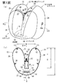
以下、図面を参照して本発明の実施の形態について説明する。第1図(a)は本発明の実施の形態に係るエアバッグの膨張状態における斜視図、第1図(b)は第1図(a)のB−B線に沿う断面図、第2図は第1図(b)のII−II線に沿う断面図、第3図(a)はこのエアバッグの分解斜視図、第3図(b)は同(a)のB部分の拡大図である。 Hereinafter, embodiments of the present invention will be described with reference to the drawings. 1 (a) is a perspective view of an airbag according to an embodiment of the present invention in an inflated state, FIG. 1 (b) is a sectional view taken along line BB of FIG. 1 (a), and FIG. 1 is a sectional view taken along the line II-II of FIG. 1 (b), FIG. 3 (a) is an exploded perspective view of the airbag, and FIG. 3 (b) is an enlarged view of a portion B of FIG. 1 (a). is there.
このエアバッグ10は、乗員前方の右側において膨張する右半側エアバッグ12と、乗員前方の左側において膨張する左半側エアバッグ14と、該右半側エアバッグ12及び左半側エアバッグ14の一端側同士を連通する連通部16とを有している。該連通部16がエアバッグ10の基端側となっている。従って、該右半側エアバッグ12及び左半側エアバッグ14は、それぞれこの連通部16から遠ざかる方向に膨張する。
The
このエアバッグ10が膨張した状態にあっては、右半側エアバッグ12と左半側エアバッグ14の先端部同士の間にタイパネルなどの架渡部材は存在せず、両バッグ12,14の先端部同士に間に形成される空間部13は乗員に向って(即ち、第1図(b)において上方に向って)開放している。
When the
このエアバッグ10が膨張完了した状態にあっては、右半側エアバッグ12の最先端12tと左半側エアバッグ14の最先端14tとの間隔Wは150〜450mm特に170〜430mmであることが好ましい。また、この最先端12t,14tから空間部13の最奥部までの水平方向距離Aは280〜480mm特に310〜450mmであることが好ましい。
When the
このエアバッグ10は、右半側エアバッグ12の膨張方向の途中部分と左半側エアバッグ14の膨張方向の途中部分とがシーム52によって結合されている。最先端12t,14tからこのシーム52までの水平方向距離Bは50〜300mm特に90〜260mmであることが好ましい。
In the
この実施の形態では、該エアバッグ10は、パネル18,20,22,24,26,28を縫合してなるものである。パネル26,28にはそれぞれベントホール26a,28a(26aは図示略)が設けられている。これらのベントホール26a,28aは、第1図(a)に示すように、各バッグ12,14の外向きの側面に設けられている。パネル26の26aは、上記の通り図示が省略されているが、ベントホール28aと対称位置に設けられている。
In this embodiment, the
以下に、各パネル同士の縫合構成について詳細に説明する。 Hereinafter, the suturing configuration of each panel will be described in detail.
第3図(a)に示すように、パネル18(リアインナパネル)は、右半側エアバッグ12及び左半側エアバッグ14の膨張方向の途中部分よりも後端側と連通部16とのエアバッグ中央側の面を構成する。パネル20(リアアウタパネル)は、このリアインナパネル18と反対側の面(エアバッグ外側面)を構成する。
As shown in FIG. 3A, the panel 18 (rear inner panel) is formed between the
パネル22,24(フロントインナパネル)は、該右半側エアバッグ12及び左半側エアバッグ14の膨張方向の該途中部分よりも先端側のエアバッグ中央側の面(右半側エアバッグ12と左半側エアバッグ14との対向面)を構成する。
The
パネル26,28(フロントアウタパネル)は、該フロントインナパネル22,24と反対側の面(エアバッグ外側面)を構成する。
The
符号30は該リアインナパネル18とリアアウタパネル20とを縫合したシーム(縫糸)を示し、符号32,34は、それぞれ該リアインナパネル18とフロントインナパネル22,24とを縫合したシームを示し、符号36,38は該リアアウタパネル20とフロントアウタパネル26,28とを縫合したシームを示している。
符号28aはフロントアウタパネル28に設けられた左半側エアバッグ用ベントホールを示している。図示はしないが、フロントアウタパネル26にも、これと同様の右半側エアバッグ用ベントホールが設けられている。
第1図(a)に示すように、リアインナパネル18とフロントインナパネル22,24との縫合代(結合代)44,46は、それぞれ、エアバッグ製品における右半側エアバッグ12及び左半側エアバッグ14の外面に露出するように配置されている。この縫合代44,46からは、第1,2図に示すように、舌片状の連結代48,50(第2図では連結代48のみ図示。)が突設されている。そして、第1図特に第1図(b)に明示の通り、この連結代48,50同士がシーム52によって縫合されている。
As shown in FIG. 1 (a), the stitching margins (joining margins) 44, 46 between the rear
このように、該右半側エアバッグ12と左半側エアバッグ14とは、該リアインナパネル18とフロントインナパネル22,24との縫合代44,46を介してその対面部分のうち膨張方向の途中部分同士が連結されている。
In this way, the
なお、膨張したエアバッグの後端10eからシーム52までの距離は、膨張したエアバッグ10の前後方向の長さLの30〜70%特に40〜55%程度が好ましい。
The distance from the
連通部16の外側面を構成するリアアウタパネル20には、インフレータ挿通用の1対のスリット54,54が設けられている。この実施の形態では、第1図(a),(b)に示すように、棒状のインフレータ56が用いられている。該棒状インフレータ56は、該連通部16を車両幅方向に貫通するように該スリット54,54に挿通されており、該インフレータ56の両端部がエアバッグ10外に配置されている。
A pair of
このエアバッグ10は、車両衝突時に乗員を保護するためのエアバッグ装置に装備される。図示はしないが、エアバッグ装置は、例えば、このエアバッグ10を収容するための無蓋箱状のケース(図示略)を有しており、該エアバッグ10はこのケースに連結される。第1図(b)の符号58は、このエアバッグ10を該ケースに連結するためのボルト等の固着具(図示略)が挿通される孔を示している。インフレータ56の両端部もこのケース内に取り付けられている。
The
該エアバッグ10が折り畳まれて該ケース内に収容され、このエアバッグ10の折り畳み体を覆うように該ケースにリッド等のカバー(図示略)が装着されることにより、エアバッグ装置が構成される。なお、該リッドは、エアバッグ10が膨張するときに該エアバッグ10からの押圧力によって開裂するようになっている。
The
このエアバッグ装置は、例えば、自動車の助手席前方のインストルメントパネルに設置される。車両衝突時には、インフレータ56がガス噴出作動し、該インフレータ56から連通部16内にガスが噴出する。このインフレータ56からのガスは、該連通部16から右半側エアバッグ12及び左半側エアバッグ14に流入し、このガスによって該右半側エアバッグ12及び左半側エアバッグ14がそれぞれ乗員前方の右側及び左側において膨張する。
The airbag device is installed, for example, on an instrument panel in front of a passenger seat of an automobile. At the time of a vehicle collision, the
このエアバッグ10にあっては、収容時の折り畳まれた状態から右半側エアバッグ12及び左半側エアバッグ14が膨張するに際し、これらのうちどちらか一方のエアバッグ12又は14が先行して膨張し、他方のエアバッグ14又は12の膨張が遅れた場合でも、右半側エアバッグ12と左半側エアバッグ14とが連結されているので、先行して膨張した一方のエアバッグが膨張の遅れている他方のエアバッグを引張ってその膨張を促進させる。しかも、これらの右半側エアバッグ12と左半側エアバッグ14とはその膨張方向の途中部分同士がシーム52によって連結されているので、先行して膨張を開始した一方のエアバッグは、膨張開始後、比較的初期の段階で膨張の遅れている他方のエアバッグを膨張方向に引張り始める。これにより、該右半側エアバッグ12と左半側エアバッグ14の双方が膨張初期の段階からスムーズに且つ左右略均等に膨張するようになる。
In the
エアバッグ10が膨張完了した状態において、右半側エアバッグ12と左半側エアバッグ14の先端部同士の間に空間部13が形成され、この空間部13が乗員に向って開放している。そして、膨張した右半側エアバッグ12が乗員の右胸を受け止め、膨張した左半側エアバッグ14が左胸を受け止め、胸骨付近は空間部13に対峙する。このため、胸骨付近に加えられるエアバッグ受承時の反力が小さなものとなる。なお、乗員がエアバッグ10によって受承された際に、エアバッグ10内のガスがベントホール26a,28aを通って流出し、衝撃が吸収される。
When the
このエアバッグ10は、次のような手順で製作される。
This
まず、第3図(a)のようにリアインナパネル18とフロントインナパネル22,24とをシーム32,34によって縫合すると共に、リアアウタパネル20とフロントアウタパネル26,28とをシーム36,38によって縫合する。この際、リアインナパネル18とフロントインナパネル22,24との縫合代44,46はエアバッグ製品においてエアバッグ外部に露出する側に配置される。
First, as shown in FIG. 3 (a), the rear
なお、この実施の形態では、該リアインナパネル18とフロントインナパネル22との縫合代44にあっては、第3図(b)に示すように、該リアインナパネル18とフロントインナパネル22とは縫合代44の両端側のみがシーム32(32a,32b)によってそれぞれ縫合され、これらのシーム32a,32b同士の間にはエアバッグ反転用の開口60が形成される。
In this embodiment, as shown in FIG. 3 (b), the rear
次いで、エアバッグ製品とされた状態においてエアバッグ外部に露出する面が向い合うように、これらのリアインナパネル18及びフロントインナパネル22,24の縫合体と、リアアウタパネル20及びフロントアウタパネル26,28の縫合体とを重ね合わせ、その周縁部を周回するようにシーム30,40,42によってこれらを縫い合わせる。これにより、裏返し状のエアバッグ製品中間体が製作される。
Next, the rear
次に、このエアバッグ製品中間体を、縫合代44に形成された開口60を介して表裏反転させる。その後、縫合代44,46の連結代48,50同士をシーム52によって縫合することにより、エアバッグ10製品が完成する。
Next, the airbag product intermediate is turned upside down through an
なお、連結代48,50同士を縫合するに際し、上記開口60はシーム52によって閉鎖される。
The
このようにエアバッグ10を複数枚のパネルから構成することにより、大面積で複雑な形状を有するエアバッグ10の外表面を比較的小面積のパネルから無駄なく製作することができる。
By configuring the
この実施の形態では、実質的にリアインナパネル18とフロントインナパネル22,24との縫合代44,46同士を連結することにより右半側エアバッグ12と左半側エアバッグ14とを連結したことにより、各パネル18,22,24等とは別に右半側エアバッグ12と左半側エアバッグ14とを連結するタイパネルを用いることが不要となり、エアバッグ10の構成コストが低減される。
In this embodiment, the right half-
この実施の形態では、連通部16のリアアウタパネル20にインフレータ用開口として1対のスリット54,54を設け、これらのスリット54,54に棒状のインフレータ56を挿通して該インフレータ56を連通部16内に配置している。このようにインフレータ用開口をスリット状とした場合には、インフレータ56のエアバッグ10への接続強度が高い。
In this embodiment, a pair of
この実施の形態では、エアバッグ製作過程において上記のように縫合代44にエアバッグ製品反転用の開口60を設けたことより、ベントホールやインフレータ用開口からではエアバッグ製品中間体を反転しにくい場合でも、特にこの実施の形態のようにインフレータ用開口をスリット状とした場合でも、この開口60を介して容易にエアバッグ製品中間体を表裏反転させることができる。
In this embodiment, since the
なお、この開口60は連結代48,50同士を縫合した際にシーム52によって閉鎖されるため、インフレータ56から右半側エアバッグ12及び左半側エアバッグ14に導入されたガスがこの開口60から漏れ出すことはない。
Since the
上記の実施の形態は本発明の一例を示すものであり、本発明は図示の形態に限定されるものではない。例えば、上記実施の形態では右半側エアバッグ12と左半側エアバッグ14とは基端側において連なっているが、両バッグが別体とされてもよい。左半側エアバッグと右半側エアバッグとは別個のインフレータによって膨張されるよう構成されてもよい。左半側エアバッグと右半側エアバッグとの途中部分同士は、パネルや紐、ネットなどによって連結されてもよい。
The above embodiment is an example of the present invention, and the present invention is not limited to the illustrated embodiment. For example, in the above embodiment, the right half-
本発明では、左半側エアバッグと右半側エアバッグとは対称形状であってもよく、非対称形状であってもよい。また、左半側エアバッグと右半側エアバッグの容積は同一であってもよく、異なってもよい。 In the present invention, the left half airbag and the right half airbag may have a symmetrical shape or an asymmetrical shape. Further, the volumes of the left half airbag and the right half airbag may be the same or different.
本発明では、第4図の如く、Aピラー側に配置されるサイドのバッグ(第4図では右半側エアバッグ12A)がAピラーやウィンドシールドあるいはサイドウィンドになるべく接しないように、バッグ上部を車室内に傾斜させるよう構成してもよい。
In the present invention, as shown in FIG. 4, the upper bag is arranged so that the side bag (right
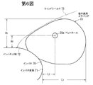
本発明では、第5図の如くエアバッグは上方ほど左右幅が小さくなる膨張形状とされてもよい。 In the present invention, as shown in FIG. 5, the airbag may have an inflated shape in which the left-right width becomes smaller toward the upper side.
本発明のエアバッグは、比較的低圧のガスにて膨張させた場合でも十分に乗員を保護することができる。特に、左半側エアバッグ14及び右半側エアバッグ12がそれぞれ45L(リットル)特に50L以上(好ましくは65L以下)の容積を有する場合には、膨張ガス圧が低くてもきわめて十分に乗員を保護することができる。この場合、ガス発生器単体での測定による圧(60リットルタンク圧)が440kPa以下、あるいは400kPa以下、場合によっては350kPa以下であっても、十分な乗員保護作用を奏する。ただし、膨張ガス圧(内圧)は310kPa以上特に360kPa以上であることが望ましい。
The airbag of the present invention can sufficiently protect the occupant even when inflated with a relatively low-pressure gas. In particular, when the
本発明において、このようにエアバッグを低圧で膨張させるときに、シートに座っている乗員の体重の大小あるいは衝突時の車速の大小にかかわらず、同一ガス圧にて膨張させても乗員を十分に保護することができる。なお、従来の助手席用エアバッグにあっては、乗員の体重が大であるとき、あるいは衝突時の車速が高いときには、エアバッグ内圧を高くすべき場合があったが、本発明のエアバッグではこのような体重や衝突速度の大小にかかわらず同一のガス圧にてエアバッグを膨張させても乗員を十分に保護することができる。そのため、エアバッグシステムのコストが低くて済むようになる。 In the present invention, when the airbag is inflated at a low pressure in this manner, the occupant can be sufficiently inflated at the same gas pressure regardless of the weight of the occupant sitting in the seat or the vehicle speed at the time of collision. Can be protected. In the conventional passenger airbag, when the weight of the occupant is large or when the vehicle speed at the time of the collision is high, the airbag internal pressure may have to be increased in some cases. In this case, the occupant can be sufficiently protected even if the airbag is inflated with the same gas pressure regardless of the weight or the collision speed. Therefore, the cost of the airbag system can be reduced.
ただし、乗員が生後12ヶ月以下の乳児であるときには衝突時でもインフレータを作動させないようにしてもよい。また、チャイルドシートが後向きに設置されている場合には衝突時でもインフレータを作動させないようにしてもよい。 However, when the occupant is an infant of 12 months or less, the inflator may not be operated even at the time of collision. Further, when the child seat is installed rearward, the inflator may not be operated even at the time of collision.
本発明では、多段式に出力制御されるインフレータや、複数のインフレータを設置し、乗員の体重や車両衝突速度等に応じてガス圧を制御するようにしてもよい。 In the present invention, an inflator whose output is controlled in a multi-stage manner or a plurality of inflators may be provided to control the gas pressure according to the weight of the occupant, the vehicle collision speed, and the like.
上記エアバッグ10を採用した助手席用エアバッグ装置におけるベントホール26a,28aの好適な位置について第6図を参照して説明する。
The preferred positions of the
第6図の通り、この助手席用エアバッグ装置はインパネ70の上向きの面に設置されている。図示はしないが、エアバッグ10は折り畳まれてコンテナ内に収容され、このコンテナの前面開口がリッドで覆われている。このリッドはインパネの一部であってもよく、インパネと別体であってもよい。
As shown in FIG. 6, this passenger airbag device is installed on the upper surface of the
エアバッグ10が膨張完了した状態において、前述の通り、ベントホール26a,28aは各バッグ12,14の側外方を向いた側面の略中央付近又はそれよりも車両前方且つ上方の領域に配置されている。
As described above, when the
最も好適には、ベントホール26a,28aの位置(正確には、各ベントホールの中心位置)は、インパネ後端(インパネ外面のうち最も車両後方側の点)71からエアバッグ10の後端までの水平方向距離をL1とし、インパネ後端71からベントホール26a,28aの中心までの水平方向距離をL2とした場合、L2/L1が0.25〜0.5特に好ましくは0.26〜0.45となるものである。また、インパネ上端(エアバッグ装置周囲のインパネ外面のうち最も上位となる箇所。この実施の形態では、インパネのウィンドシールド直近位置。)72からエアバッグ10の上端までの鉛直方向距離をH1とし、ベントホール26a,28aまでの鉛直方向距離をH2とした場合に、H2/H1が0.3〜0.5特に0.32〜0.40であることが好適である。
Most preferably, the positions of the vent holes 26a and 28a (accurately, the center positions of the vent holes) are from the rear end of the instrument panel (the most rear side of the instrument panel on the vehicle rear side) 71 to the rear end of the
ベントホール26a,28aを上記配置とすることにより、ベントホール26a,28aから流出したガスが乗員を直射することが防止される。また、ベントホール26a,28aがサイドウィンドやAピラー、あるいはウィンドシールド73などの車両部材表面に密着状に重なることが防止され、ベントホール26a,28aからガスがスムーズに流出する。
By arranging the vent holes 26a and 28a as described above, the gas flowing out of the vent holes 26a and 28a is prevented from directly irradiating the occupant. Further, the
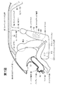
本発明のエアバッグを備えた車両にあっては、ニーバッグ装置など他の種類のエアバッグ装置やニープロテクタが搭載されてもよい。第7図はかかる車両の一例を示す車両前後方向の概略的な縦断面図である。 In a vehicle including the airbag of the present invention, another type of airbag device such as a knee bag device or a knee protector may be mounted. FIG. 7 is a schematic longitudinal sectional view in the vehicle front-rear direction showing an example of such a vehicle.
インパネ70の上向き面に上記本発明のエアバッグよりなる助手席用エアバッグ10を有した助手席用エアバッグ装置が設置されている。
A passenger airbag device having the
インパネ70の下部にニーバッグ装置80が設置されている。この実施の形態では、インパネ70内にニーバッグ用のケース82が設置されている。該ケース82内にニーバッグ84が折り畳まれて収納され、留付部材によってケース82に留め付けられている。ケース82内には、該ニーバッグ84を膨張させるためのインフレータ(ガス発生器)18が設置されている。このケース82はインパネ70に沿って開放する開口を有しており、この開口がリッド86で覆われている。
A knee bag device 80 is installed below the
自動車が衝突すると、インフレータ88がガスを噴出し、ニーバッグ84が膨張する。膨張するニーバッグ84に押されてリッド86が開き出す。そして、ニーバッグ84がケース82の前面部及びその周囲のインパネ70に沿って展開する。このニーバッグ84が乗員脚部を受け止め、乗員脚部が保護される。
When the vehicle collides, the inflator 88 emits gas and the knee bag 84 expands. The lid 86 is opened by being pushed by the inflating knee bag 84. Then, the knee bag 84 is deployed along the front portion of the
なお、この実施の形態では、ニーバッグ84及びエアバッグ10がそれぞれ完全に膨張した状態において(但し、乗員は存在しない状態とする。)、ニーバッグ84の上端部はエアバッグ30の下端部よりも若干上方に位置する。
In this embodiment, the upper end of the knee bag 84 is slightly larger than the lower end of the
この車両には、さらに、カーテンエアバッグ装置90、サイドエアバッグ装置100、シートクッションバッグ装置110が設置されている。 The vehicle is further provided with a curtain airbag device 90, a side airbag device 100, and a seat cushion bag device 110.
カーテンエアバッグ装置90は、Aピラー91からBピラー92の上方を経てさらにCピラー93にまで延在するカーテンエアバッグ94と、このカーテンエアバッグ94を膨張させるためのインフレータ95とを有する。このカーテンエアバッグ94は、細長く折り畳まれた形態にてAピラー91からルーフサイド部96を経てCピラー93にまで配置され、ピラーガーニッシュやルーフトリム等によって覆われている。
The curtain airbag device 90 has a curtain airbag 94 extending from the A pillar 91 to a position above the B pillar 92 and further to the C pillar 93, and an inflator 95 for inflating the curtain airbag 94. The curtain airbag 94 is disposed from the A-pillar 91 to the C-pillar 93 via the
車両の衝突時や横転時等にインフレータ95が作動すると、カーテンエアバッグ94はピラーガーニッシュやルーフトリム等を押し開けて車両室内に膨張し、各ピラー91,92,93及びサイドドアに沿って下方に展開する。展開したカーテンエアバッグ94は、乗員を受け止めて衝撃を吸収したり、あるいは乗員の車外放出を防止する作用を奏する。 When the inflator 95 is activated at the time of collision or rollover of the vehicle, the curtain airbag 94 pushes open the pillar garnish or the roof trim and inflates into the vehicle interior, and extends downward along the pillars 91, 92, 93 and side doors. Expand to The deployed curtain airbag 94 has an effect of receiving an occupant and absorbing an impact, or preventing the occupant from being released from the vehicle.
上記サイドエアバッグ装置100は、シートバック101内に設置されている。このサイドエアバッグ装置100は、折り畳まれてケース102内に収容されたサイドエアバッグ103と、このサイドエアバッグ103を膨張させるためのインフレータ104とを備えている。
The side airbag device 100 is installed in a seat back 101. The side airbag device 100 includes a
車両の衝突時や横転時等にインフレータ104が作動すると、サイドエアバッグ103はシートバックカバーを押し破って膨張し、乗員上半部のドア側の側方領域に展開し、乗員を保護する。
When the inflator 104 is activated at the time of a collision or rollover of the vehicle, the
なお、サイドエアバッグ装置は、シートバック以外の箇所例えばサイドドアに設置されてもよい。 Note that the side airbag device may be installed at a location other than the seat back, for example, at a side door.
上記シートクッションバッグ装置110は、シートクッション111の前部の内部又は下側に配置されたシートクッションバッグ112と、これを膨張させるためのインフレータ(図示略)とを有する。車両の前突時にこのインフレータが作動し、シートクッションバッグ112が膨張してシートクッション111が上方に向って押圧される。これにより、シートクッション111の前部が上方に押圧されるか又は密度が高くなって硬くなる。この結果、乗員の下半身が前方へ移動することが抑制される。なお、符号106はシートベルト(ラップベルト)を示す。
The seat cushion bag device 110 includes a
10 エアバッグ
10e エアバッグの後端
12,12A,12B 右半側エアバッグ
12t 右半側エアバッグの最先端
13 空間部
14,14A,14B 左半側エアバッグ
14t 左半側エアバッグの最先端
16 連通部
18 リアインナパネル
20 リアアウタパネル
22,24 フロントインナパネル
26,28 フロントアウタパネル
44,46 縫合代
48,50 連結代
52 シーム
56 インフレータ
70 インパネ
80 ニーバッグ装置
90 カーテンエアバッグ装置
100 サイドエアバッグ装置
110 シートクッションバッグ装置
DESCRIPTION OF
Claims (12)
乗員前方の左側において膨張する左半側エアバッグと、
乗員前方の右側において膨張する右半側エアバッグと
を有するエアバッグにおいて、
該左半側エアバッグ及び右半側エアバッグの先端部同士が非連結状となっており、
該エアバッグが膨張した状態において該左半側エアバッグ及び右半側エアバッグの先端部同士の間に、乗員に向って開放する空間部が形成されることを特徴とするエアバッグ。 An airbag in which the tip side is inflated in a direction away from the base side by the gas discharged from the inflator disposed on the base side,
A left airbag inflated on the left side in front of the occupant;
An airbag having a right half airbag that inflates on the right side in front of the occupant,
The distal ends of the left half airbag and the right half airbag are uncoupled,
An airbag, wherein a space opening toward an occupant is formed between the distal ends of the left half airbag and the right half airbag when the airbag is inflated.
該最先端から前記空間部の最奥部までの水平方向距離が280〜480mmであることを特徴とするエアバッグ。 In Claim 1, in the state where the airbag is inflated, the interval between the extreme ends of the left half airbag and the right half airbag is 150 to 450 mm,
An airbag, wherein a horizontal distance from the front end to the innermost part of the space is 280 to 480 mm.
膨張した左半側エアバッグ及び右半側エアバッグの最先端から、連結された該途中部分同士までの水平方向距離が50〜300mmであることを特徴とするエアバッグ。 The intermediate portion in the inflation direction among the facing portions of the left half-side airbag and the right half-side airbag according to any one of claims 1 to 3,
An airbag, wherein a horizontal distance from the leading ends of the inflated left half airbag and right half airbag to the connected middle portions is 50 to 300 mm.
左半側エアバッグ及び右半側エアバッグの対面部分のうち該途中部分に配置された該結合代同士が連結されていることを特徴とするエアバッグ。 In Claim 4, each of the left half airbag and the right half airbag is formed by connecting a plurality of panels, and a margin for connecting the panels is disposed on the bag outer surface at the intermediate portion. ,
An airbag, wherein the connecting margins disposed in the middle portion of the facing portions of the left half airbag and the right half airbag are connected to each other.
該インストルメントパネルの後端からの膨張したエアバッグのベントホールまでの水平方向距離L2と先端までの水平方向距離L1との比L2/L1が0.25〜0.5であることを特徴とする車両。 The airbag device according to claim 9, wherein the airbag device is a passenger seat airbag device installed on an instrument panel of a vehicle, and a vent hole is provided on a side surface of the airbag that faces outward and outward,
The ratio L 2 / L 1 of the horizontal distance L 1 to the horizontal distance L 2 and the tip to the vent hole of the inflated air bag from the rear end of the instrument panel is a 0.25 to 0.5 A vehicle characterized in that:
該インストルメントパネルの上端からの膨張したエアバッグのベントホールまでの鉛直方向距離H2と上端までの鉛直方向距離H1との比H2/H1が0.3〜0.5であることを特徴とする車両。 The airbag device according to claim 9 or 10, wherein the airbag device is a passenger-seat airbag device installed on an instrument panel of a vehicle, and a vent hole is provided on a side surface of the airbag that faces outward.
The ratio H 2 / H 1 and the vertical distance H 1 to the vertical distance H 2 and the upper end to the vent hole of the inflated airbag from the upper end of the instrument panel is 0.3 to 0.5 A vehicle characterized by the following.
Priority Applications (3)
| Application Number | Priority Date | Filing Date | Title |
|---|---|---|---|
| JP2003413504A JP4367120B2 (en) | 2003-01-23 | 2003-12-11 | Passenger seat airbag, passenger seat airbag apparatus and vehicle |
| US10/771,347 US7093853B2 (en) | 2003-01-23 | 2004-02-05 | Airbag, airbag device and vehicle |
| US11/502,543 US7267366B2 (en) | 2003-01-23 | 2006-08-11 | Airbag, airbag device and vehicle |
Applications Claiming Priority (2)
| Application Number | Priority Date | Filing Date | Title |
|---|---|---|---|
| JP2003015108 | 2003-01-23 | ||
| JP2003413504A JP4367120B2 (en) | 2003-01-23 | 2003-12-11 | Passenger seat airbag, passenger seat airbag apparatus and vehicle |
Publications (3)
| Publication Number | Publication Date |
|---|---|
| JP2004244006A true JP2004244006A (en) | 2004-09-02 |
| JP2004244006A5 JP2004244006A5 (en) | 2005-09-15 |
| JP4367120B2 JP4367120B2 (en) | 2009-11-18 |
Family
ID=33032035
Family Applications (1)
| Application Number | Title | Priority Date | Filing Date |
|---|---|---|---|
| JP2003413504A Expired - Fee Related JP4367120B2 (en) | 2003-01-23 | 2003-12-11 | Passenger seat airbag, passenger seat airbag apparatus and vehicle |
Country Status (1)
| Country | Link |
|---|---|
| JP (1) | JP4367120B2 (en) |
Cited By (8)
| Publication number | Priority date | Publication date | Assignee | Title |
|---|---|---|---|---|
| JP2006088987A (en) * | 2004-09-27 | 2006-04-06 | Toyoda Gosei Co Ltd | Air bag for front passenger seat |
| JP2006103670A (en) * | 2004-09-09 | 2006-04-20 | Toyoda Gosei Co Ltd | Airbag for front passenger seat |
| JP2007022417A (en) * | 2005-07-20 | 2007-02-01 | Mazda Motor Corp | Occupant crash protection device for passenger seat of vehicle |
| JP2007022416A (en) * | 2005-07-20 | 2007-02-01 | Mazda Motor Corp | Occupant crash protection device for passenger seat of vehicle |
| WO2007055234A1 (en) * | 2005-11-10 | 2007-05-18 | Takata Corporation | Airbag and airbag device |
| JP2009149295A (en) * | 2007-12-19 | 2009-07-09 | Dalphi Metal Espana Sa | Optimized airbag module |
| JP2009227047A (en) * | 2008-03-21 | 2009-10-08 | Toyota Motor Corp | Airbag system |
| RU2695014C1 (en) * | 2017-08-21 | 2019-07-18 | Тойота Дзидося Кабусики Кайся | Passenger protection device for front passenger seat |
-
2003
- 2003-12-11 JP JP2003413504A patent/JP4367120B2/en not_active Expired - Fee Related
Cited By (15)
| Publication number | Priority date | Publication date | Assignee | Title |
|---|---|---|---|---|
| JP2006103670A (en) * | 2004-09-09 | 2006-04-20 | Toyoda Gosei Co Ltd | Airbag for front passenger seat |
| JP4645374B2 (en) * | 2004-09-09 | 2011-03-09 | 豊田合成株式会社 | Passenger airbag |
| JP2006088987A (en) * | 2004-09-27 | 2006-04-06 | Toyoda Gosei Co Ltd | Air bag for front passenger seat |
| JP2007022416A (en) * | 2005-07-20 | 2007-02-01 | Mazda Motor Corp | Occupant crash protection device for passenger seat of vehicle |
| JP2007022417A (en) * | 2005-07-20 | 2007-02-01 | Mazda Motor Corp | Occupant crash protection device for passenger seat of vehicle |
| WO2007055234A1 (en) * | 2005-11-10 | 2007-05-18 | Takata Corporation | Airbag and airbag device |
| JP2007153290A (en) * | 2005-11-10 | 2007-06-21 | Takata Corp | Airbag and airbag device |
| US7841622B2 (en) | 2005-11-10 | 2010-11-30 | Takata Corporation | Airbag and airbag apparatus |
| JP2009149295A (en) * | 2007-12-19 | 2009-07-09 | Dalphi Metal Espana Sa | Optimized airbag module |
| JP2009227047A (en) * | 2008-03-21 | 2009-10-08 | Toyota Motor Corp | Airbag system |
| JP4678416B2 (en) * | 2008-03-21 | 2011-04-27 | トヨタ自動車株式会社 | Airbag device |
| US7946618B2 (en) | 2008-03-21 | 2011-05-24 | Toyota Jidosha Kabushiki Kaisha | Airbag device |
| RU2695014C1 (en) * | 2017-08-21 | 2019-07-18 | Тойота Дзидося Кабусики Кайся | Passenger protection device for front passenger seat |
| US11001221B2 (en) | 2017-08-21 | 2021-05-11 | Toyota Jidosha Kabushiki Kaisha | Passenger protection device for front passenger seat |
| US11001220B2 (en) | 2017-08-21 | 2021-05-11 | Toyota Jidosha Kabushiki Kaisha | Passenger protection device for front passenger seat |
Also Published As
| Publication number | Publication date |
|---|---|
| JP4367120B2 (en) | 2009-11-18 |
Similar Documents
| Publication | Publication Date | Title |
|---|---|---|
| US7267366B2 (en) | Airbag, airbag device and vehicle | |
| JP4400188B2 (en) | Air bag, air bag device and vehicle | |
| US7461862B2 (en) | Airbag and airbag system | |
| US7458605B2 (en) | Airbag, airbag system and vehicle | |
| JP3922057B2 (en) | Head protection airbag and head protection airbag device | |
| US7152877B2 (en) | Airbag and airbag apparatus | |
| US8851508B1 (en) | Delayed vent in airbag curtain | |
| EP1671852B1 (en) | Airbag and airbag system | |
| US20040145161A1 (en) | Airbag and airbag apparatus | |
| JP2007008219A (en) | Occupant restraint system | |
| JP2003034215A (en) | Device for occupant protection | |
| JP5776453B2 (en) | Air bag, air bag device and vehicle | |
| JP2009143483A (en) | Airbag for front passenger seat, airbag device for front passenger seat, and automobile | |
| JP2017065398A (en) | Head protection airbag device | |
| JP5930633B2 (en) | Air bag, air bag device and vehicle | |
| JP4654645B2 (en) | Air bag and air bag device | |
| JP2006142964A (en) | Head protecting air bag and head protecting air bag device | |
| US9415742B1 (en) | Three-way gas guide | |
| JP2004244005A (en) | Airbag and airbag device | |
| JP4367120B2 (en) | Passenger seat airbag, passenger seat airbag apparatus and vehicle | |
| US6736422B2 (en) | Head-protecting bag device | |
| JP2000006750A (en) | Head protective airbag device for front and rear seats | |
| JP2001080446A (en) | Head protective air bag | |
| EP1630047B1 (en) | Airbag and airbag apparatus | |
| JP2008018936A (en) | Air-bag |
Legal Events
| Date | Code | Title | Description |
|---|---|---|---|
| A521 | Written amendment |
Free format text: JAPANESE INTERMEDIATE CODE: A523 Effective date: 20041208 |
|
| A521 | Written amendment |
Free format text: JAPANESE INTERMEDIATE CODE: A523 Effective date: 20050531 |
|
| A711 | Notification of change in applicant |
Free format text: JAPANESE INTERMEDIATE CODE: A712 Effective date: 20060317 |
|
| A621 | Written request for application examination |
Free format text: JAPANESE INTERMEDIATE CODE: A621 Effective date: 20061031 |
|
| A977 | Report on retrieval |
Free format text: JAPANESE INTERMEDIATE CODE: A971007 Effective date: 20081127 |
|
| A131 | Notification of reasons for refusal |
Free format text: JAPANESE INTERMEDIATE CODE: A131 Effective date: 20081209 |
|
| A521 | Written amendment |
Free format text: JAPANESE INTERMEDIATE CODE: A523 Effective date: 20090123 |
|
| A131 | Notification of reasons for refusal |
Free format text: JAPANESE INTERMEDIATE CODE: A131 Effective date: 20090217 |
|
| A521 | Written amendment |
Free format text: JAPANESE INTERMEDIATE CODE: A523 Effective date: 20090330 |
|
| TRDD | Decision of grant or rejection written | ||
| A01 | Written decision to grant a patent or to grant a registration (utility model) |
Free format text: JAPANESE INTERMEDIATE CODE: A01 Effective date: 20090804 |
|
| A01 | Written decision to grant a patent or to grant a registration (utility model) |
Free format text: JAPANESE INTERMEDIATE CODE: A01 |
|
| A61 | First payment of annual fees (during grant procedure) |
Free format text: JAPANESE INTERMEDIATE CODE: A61 Effective date: 20090817 |
|
| R150 | Certificate of patent or registration of utility model |
Free format text: JAPANESE INTERMEDIATE CODE: R150 |
|
| FPAY | Renewal fee payment (event date is renewal date of database) |
Free format text: PAYMENT UNTIL: 20120904 Year of fee payment: 3 |
|
| FPAY | Renewal fee payment (event date is renewal date of database) |
Free format text: PAYMENT UNTIL: 20130904 Year of fee payment: 4 |
|
| R250 | Receipt of annual fees |
Free format text: JAPANESE INTERMEDIATE CODE: R250 |
|
| R250 | Receipt of annual fees |
Free format text: JAPANESE INTERMEDIATE CODE: R250 |
|
| R250 | Receipt of annual fees |
Free format text: JAPANESE INTERMEDIATE CODE: R250 |
|
| R250 | Receipt of annual fees |
Free format text: JAPANESE INTERMEDIATE CODE: R250 |
|
| R250 | Receipt of annual fees |
Free format text: JAPANESE INTERMEDIATE CODE: R250 |
|
| S111 | Request for change of ownership or part of ownership |
Free format text: JAPANESE INTERMEDIATE CODE: R313113 |
|
| S343 | Written request for registration of root pledge or change of root pledge |
Free format text: JAPANESE INTERMEDIATE CODE: R316354 |
|
| SZ02 | Written request for trust registration |
Free format text: JAPANESE INTERMEDIATE CODE: R316Z02 |
|
| S343 | Written request for registration of root pledge or change of root pledge |
Free format text: JAPANESE INTERMEDIATE CODE: R316354 |
|
| R350 | Written notification of registration of transfer |
Free format text: JAPANESE INTERMEDIATE CODE: R350 |
|
| S343 | Written request for registration of root pledge or change of root pledge |
Free format text: JAPANESE INTERMEDIATE CODE: R316354 |
|
| SZ02 | Written request for trust registration |
Free format text: JAPANESE INTERMEDIATE CODE: R316Z02 |
|
| R350 | Written notification of registration of transfer |
Free format text: JAPANESE INTERMEDIATE CODE: R350 |
|
| LAPS | Cancellation because of no payment of annual fees |