【0001】
【発明の属する技術分野】
本発明は、伝送する光信号を平行光束に変換する光コリメータ素子とその製造方法並びに、この光コリメータ素子に光半導体素子やフェルールその他の光学部品素子を結合した光コリメータモジュールに関し、光通信や光ピックアップなどの技術分野で利用することができる。
【0002】
【従来の技術】
この種の光コリメータモジュールは、例えばレーザーダイオードなどの半導体発光素子から出射した光信号を、コリメータレンズで平行光束に変換して光ファイバに伝送したり、光ファイバで伝送した平行光束の光信号を、コリメータレンズで集光してフォトダイオードなどの半導体受光素子に入射したり、中間にコリメータレンズを介在し、半導体発光素子と半導体受光素子の間で光信号の授受を行う場合など、に使用されている。
【0003】
これらの用途に使用される光コリメータモジュールでは、伝送損失その他の性能を低下を少なくするために、コリメータレンズと光半導体素子やフェルールその他の光学部品との光軸を容易且つ高精度で調芯できること、現場での接続作業を容易且つ迅速に行える構造であること、製造コストを安価にするために大量生産が可能であること、情報量の増加による光ファイバの多芯化及び小径化に備え、単芯及び多芯の双方に適合すること、などが要求される。
【0004】
図1は、従来技術による光学機能モジュール1の一例を示すものであり、基板2上には光学素子として、左右の対称位置に光ファイバ3a,4aを装着したフェルール3,4とコリメータレンズ5a,6aを装着したレンズユニット5,6を配置すると共に、中央には光フィルタ又は光アッテネータ或いは光スイッチなどによる光学部品7aを装着した光学部品ユニット7を配置している。
【0005】
この光学機能モジュール1では、いずれか一方の光ファイバ3a(4a)によって伝送された光信号がフェルール3(4)を介してコリメータレンズ5a(6a)に出射され、コリメータレンズ5a(6a)で平行光束8に変換され、光回路部品7aを通過する際にろ過又は減衰或いは切換などの制御を受けた後に、コリメータレンズ6a(5a)で集光されると共に、フェルール4(3)を介して他方の光ファイバ4a(3a)に入射して伝送される。
【0006】
この光学機能モジュール1は、光軸調整装置を用いて各光学素子間の光軸を整合させる調芯作業を行って所定位置に位置決めした後に、基板2に対して各光学部品をレーザ溶接などの溶接手段によって固着するが、光軸の調芯作業を正確に行うために高価な機材の使用が必要であると共に、多くの時間を要してコストの低減を図ることが困難であり、また小形化も困難であった。
【0007】
この従来技術による光軸の調芯作業その他を改善するために、例えば特許文献1及び特許文献2に開示された発明を含めて各種の提案がなされているが、光コリメータモジュールに求められている上記した要件を十分に満足させることはできず、解決を必要とする後述するような課題が残されていた。
特許文献1・・・特開平11−54849号公報
特許文献2・・・特開2001−343556号公報
【0008】
特許文献1には、樹脂により球レンズをインサート成形して球レンズを抱持する一次成形ピースを作製し、次いで樹脂を用いて一次成形ピースをインサート成形して光半導体素子の装着部及びレセプタクルボアを有する樹脂ハウジングを二次成形する光モジュールの製造方法が開示されている。
【0009】
特許文献1の製造方法で作製した光モジュールは、樹脂接着剤などを用いることなく、レンズを樹脂ハウジングに固定することができ且つ、安価に大量生産が可能であると共に、図1の従来技術のようにフェルールとレンズユニットを別体にした場合に比べて、調芯作業を容易に行うことができる可能性がある。
【0010】
特許文献2には、複数の光ファイバ保持孔に光ファイバを保持した光ファイバ保持部と、複数の光学部品保持孔に光学部品(球レンズ)を保持した光学部品保持部とからなり、双方の端面露出面にガイド穴を設けると共に、当該ガイド穴にガイドピンを嵌合させて位置決めし、双方の端面露出面を面接合状態で複数の光ファイバと光学部品を光結合する多芯光コリメータ素子が開示されている。
【0011】
特許文献2の多芯光コリメータ素子は、連結にスリーブを用いてスリーブとの間を溶接するフェルール式に比べて組立時間が短くて且つサイズも小さくできると共に、V溝の加工が困難なV溝式に比べて加工費を安くでき、特に光学部品保持部を弾性変形させて光学部品を保持することによって、寸法にバラツキのある光学部品を安定して保持できるなどの効果を奏する。
【0012】
【発明が解決しようとする課題】
しかしながら、特許文献1のように、一次及び二次のインサート成形によって製作する場合には、外径が肉厚になって小形化することが困難であると共に、各インサート成形後にそれぞれ熱収縮を生ずるので、内外径や同軸度及び真円度などの寸法精度が低下する恐れがある。
【0013】
また、特許文献2のように、外径の内側に設けたガイド穴にガイドピンを嵌合して各保持部を連結する場合には、回転しないように少なくとも2個所で連結する必要があり、そのために外径が肉厚になって小形化することが困難であると共に、2個所のガイド穴を製作時に高精度で位置決めしないと光軸にずれを生ずる恐れがある。
【0014】
また、特許文献2のように、光学部品保持孔に光学部品(球レンズ)を保持する場合には、仮に光学部品を保持孔の端部から圧入すると、光学部品の挿入及び位置決めがきわめて困難あると共に、使用可能なレンズが球レンズ又はロッドレンズに限定され、光学部品保持部を弾性変形させて光学部品を保持すると、光軸にずれを生ずる恐れがあったり、振動のある場所での使用が困難である。
【0015】
本発明では、上記したような従来技術の課題を解決し得る光コリメータ素子とその製造方法並びに光コリメータモジュールを提供するものであり、特に光半導体素子やフェルールその他の光学部品を高精度な調芯状態で結合することが可能で且つ安価な光コリメータ素子とその製造方法と、この光コリメータ素子に光半導体素子や光ファイバを装着したフェルールを含むその他の光学部品を調芯状態で結合した光コリメータモジュールの提供を主たる目的としている。
【0016】
【課題を解決するための手段】
本発明による光コリメータ素子は、内部に光伝送路を形成した内筒部の外形を硬質材による外筒部で保形すると共に、光伝送路には少なくとも外側縁部を内筒部に埋設したコリメータレンズを設け、外筒部及びコリメータレンズをインサートして内筒部を樹脂材で一体成形している。
【0017】
この光コリメータ素子では、インサートした外筒部とコリメータレンズが、射出成形した内筒部を介して強固に一体接合されており、特に外径が硬質材による外筒部で保形されて外径寸法精度及び同心度を高精度にすることができると共に、コリメータレンズは外側縁部を成形樹脂材による内筒部に埋設して装着されているので、衝撃や振動に対する耐久性がある。
【0018】
本発明による光コリメータ素子の製造方法は、請求項1の光コリメータ素子を製造する方法であって、上型と下型を備えた射出成形金型内に、コリメータレンズと硬質材の外筒部とをインサートし、上型及び下型から光伝送路を形成するコアピンをそれぞれ突設して先端でコリメータレンズを狭持すると共に、上型及び下型と外筒部の上下端部との間に成形樹脂材の流入口及び流出口を設け、上型と下型及び外筒部で形成したキャビテイ内に成形樹脂材を充填し、コリメータレンズの外側縁部を埋設する態様で内筒部を一体成形する。
【0019】
この光コリメータ素子の製造方法では、外筒部とコリメータレンズをインサート部品として射出成形されるので、安価に大量生産が可能であると共に、外筒部に対するコリメータレンズの芯出し及び、内筒部に対するコリメータレンズの位置決めが射出成形金型内で行われるので、高精密な光コリメータ素子を容易に製造することが可能である。
【0020】
本発明による光コリメータモジュールは、連結用筒状部材内に対し、請求項1の光コリメータ素子を装着すると共に、光半導体素子、光ファイバを装着したフェルール、その他の光学部品のうちの少なくとも1つを装着し、端面を光コリメータ素子と突き合わせ接合して光軸を整合させる。
【0021】
この光コリメータモジュールでは、連結用筒状部材に光コリメータ素子と、光半導体素子やフェルールなどを装着するだけで、格別に調芯作業を行うことなく光軸を整合できると共に、所望に応じた任意の光学部品を着脱可能に装着して使用することが可能であり、また外筒部や連結用筒状部材を金属製にすると、溶接手段によって調芯位置で固定することもできる。
【0022】
また、本発明による光コリメータ素子及び光コリメータモジュールは、構造が簡単であって単芯及び多芯の双方に容易に適合させることができると共に、小形化を図ることが容易であり、光ファイバを装着したフェルールとして既存のジルコニア製のもの使用することが可能である。
【0023】
【発明の実施の形態】
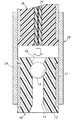
以下に、本発明の光コリメータ素子とその製造方法並びに光コリメータモジュールについて、本発明を適用した添付図面の実施形態に基づいて詳細に説明するが、図2は単芯用光コリメータ素子の縦断面図を示し、図3及び図4は図2の光コリメータ素子の製造方法の説明図を示す。
【0024】
光コリメータ素子10は、硬質材による外筒部11と、外筒部11内に一体形成された樹脂材による内筒部12と、外側縁部を内筒部12の内側に埋設する態様で軸心に一体形成されたコリメータレンズ13とで構成され、軸心には内筒部12の内側によってコリメータレンズ13の前後に形成された第1及び第2の光伝送路14,15が設けられている。
【0025】
外筒部11は、光コリメータ素子10の外径寸法精度及び軸心に対する同心度を高め、樹脂材による内筒部12を補強すると共に、後述するように外周にスリーブなどの連結用筒状部材を被着して摺動可能にする機能を有し、耐熱性や耐蝕性も必要であり、例えばステンレス材などの硬質金属材やジルコニアなどの使用が望ましく、図示の実施形態では安価で溶接も可能なステンレス材を用いているが、上記機能を満たすものであれば他の硬質材料を使用しても良い。
【0026】
外筒部11の形状は、図示の実施形態では円筒状にしているが、円筒状に限らず所望に応じて方形状その他の形状を採ることも可能であり、また図示の実施形態では外筒部11の長さを短めにして両端に内筒部12が露出する態様にし、軸方向に係止できるようにしているが、外筒部11の長さを内筒部12と等しく形成し、外筒部11の内面に内筒部12の外面に対する係止突起を設ける形態を採ることもできる。
【0027】
特に図示の実施形態のようにすると、相手側の光学素子との突き合わせ精度を向上するために、端面を仕上げ加工することが容易であること、後述するように連結用筒状体に装着する際に、端部が金属などの硬質材より樹脂材の方が連結用筒状体の内面を損傷する恐れが無いこと、挿入を容易にするために先端側の外周を面取り加工することが容易であること、後述する外筒部をインサートした射出成形が容易であること、などの点でより望ましい。
【0028】
内筒部12は、外筒部11とコリメータレンズ13とをインサート成形によって一体化させると共に、軸心に第1及び第2の光伝送路14,15を形成する機能を有し、光コリメータ素子1の両端側に結合される各光学素子に対して、光伝送路14,15を介して光信号の授受を行うので、光伝送路14,15の断面形状は円筒状に限らず、光信号の伝送を阻害しない範囲内で各種の断面形状を採り得るものである。
【0029】
内筒部12の成形樹脂材は、各種の熱可塑性樹脂材の中から、望ましくは液晶ポリマーやポリエーテルエーテルケトン(PEEK材)或いはポリフェニルサルファイド(PPS)などによるエンジニアリングプラスチックの中から所望な機械的強度や寸法精度などが得られる成形樹脂材を選択して射出成形できるが、図示の実施形態では熱膨張係数がステンレス材と近似して加工性も良いことなどの理由で、特に液晶ポリマーを使用している。
【0030】
コリメータレンズ13は、図示の実施形態ではガラス製の球レンズを使用しているが、コリメート機能を備えているものならばロッドレンズや非球面レンズを使用することが可能であると共に、予め射出成形によって製作した樹脂製のレンズ(モールドレンズ)をインサートして使用することも可能である。
【0031】
この光コリメータ素子10は、インサートした外筒部11とコリメータレンズ13が、射出成形した内筒部12を介して強固に一体接合されており、特に外径が硬質材による外筒部11で保形されて外径寸法精度及び同心度を高精度にすることができると共に、コリメータレンズ13は外側縁部を成形樹脂材による内筒部12に埋設して装着されているので、衝撃や振動に対する耐久性がある。
【0032】
光コリメータ素子10の製造は、図3のように上型16Aと下型16Bを備えた射出成形金型16内に、ステンレスパイプによる外筒部11と球レンズによるコリメータレンズ13をインサート部品として装着するが、上型16A及び下型16Bから光伝送路14,15を形成するコアピンA1,B1を突設し、コアピンA1,B1の先端でコリメータレンズ13を狭持する。
【0033】
また、上型16A及び下型16Bと外筒部11の上下端部との間には成形樹脂材の流入口D1及び流出口D2を設け、上型16Aと下型16B及び外筒部11で囲まれたキャビティC内に対し、液晶ポリマーによる成形樹脂材を矢印のように、流入口D1から流入させて流出口D2から流出させると、図4のようにキャビテイC内に内筒部12となる樹脂成形部17が成形される。
【0034】
射出成形後には、上型16Aと下型16Bを離型させて樹脂成形部17を射出成形金型16内から取り出し、樹脂成形部17の不要な樹脂成形部17a〜17dを除去した後に、樹脂成形部17の両端側外径が外筒部11の外径と面一になるように研磨などによって内筒部12の仕上げ処理を行うと、図2で示す光コリメータ素子10を製造することができる。
【0035】
この光コリメータ素子10の製造方法では、外筒部11とコリメータレンズ13をインサート部品として射出成形されるので、安価に大量生産が可能であると共に、外筒部11に対するコリメータレンズ13の芯出し及び、内筒部12に対するコリメータレンズ13の位置決めが射出成形金型16内で行われるので、高精密な光コリメータ素子10を容易に製造することが可能である。
【0036】
特に、インサートしたコリメータレンズ13は上型16Aと下型16Bに設けたコアピンA1,B1で狭持され、正確に位置決めされた状態で内筒部12を形成する樹脂成形部17に外側縁部が埋設されるので、振動や衝撃などによって位置ズレすることなく安定状態で光コリメータ素子10内に装着されると共に、コリメータレンズ13を狭持したコアピンA1,B1によって、光伝送路14,15を形成する容易に形成することができる。
【0037】
光コリメータ素子10は、光半導体素子やフェルールやその他の光学部品と連結して光軸の調芯作業を必要としない光コリメータモジュールを構成することが可能であり、例えば図5及び図6の実施形態では、連結用筒状部材18を介してフェルール19と連結した光コリメータモジュール20を示す。
【0038】
光コリメータモジュール20は、連結用筒状部材18の一端側から光伝送路15側の端部を先端にして光コリメータ素子10を挿入すると共に、連結用筒状部材18の他端側からフェルール19の先端側を挿入し、光コリメータ素子10の先端側とフェルール19の先端側を突き合わせすると、両者は光軸が整合した状態で連結される。
【0039】
これによって、フェルール19に装着されたファイバ芯線21から光伝送路15に出射した光信号22は、コリメータレンズ13で平行光束に変換された後に、光伝送路14を介して光コリメータモジュール20の外部へ伝送され、また外部から光伝送路14を介してコリメータレンズ13に入射された平行光束による光信号22は、ファイバ芯線21に集光されて光ファイバ19から光コリメータモジュール20の外部へ伝送される。
【0040】
この光コリメータモジュール20では、連結用筒状部材18に光コリメータ素子10とフェルール19を装着するだけで、格別に調芯作業を行うことなく光軸を整合させることができると共に、使用するフェルール19は先端にジルコニア製のフェルールを含む従来公知の各種フェルールの使用が可能であるが、図示の実施形態では外周にステンレスパイプ22をインサート成形した樹脂製のフェルールを装着している。
【0041】
また連結用筒状部材18は、従来からフェルールを介して光ファイバを相互に連結する際に使用されている円筒状の割りスリーブや、割りのない円筒スリーブを用いることができると共に、これらスリーブ類による連結用筒状部材18の材質には、ジルコニア製のものやステンレス製のもの硬質樹脂製のものなどの使用が可能であり、特に光コリメータモジュールを基板に溶接して使用する用途の場合には、ステンレス製などの金属製スリーブが望ましい。
【0042】
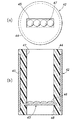
次に、図7〜10では2芯以上の多芯のフェルールを装着する光コリメータ素子及び、光コリメータモジュールの実施形態を説明するが、図7で示す2芯用光コリメータ素子23は、外筒部24と内筒部25及びコリメータレンズ26で構成されており、この2芯用光コリメータ素子23を用いると、例えば図8で示すような光コリメータモジュール29を造ることができる。
【0043】
2芯用光コリメータ素子23は、図2で示す単芯の光コリメータ素子10と同様の材料が使用されると共に、外筒部24とコリメータレンズ26をインサートして図3及び図4と同様に内筒部25を射出成形することができるが、光コリメータ素子10と相違する点は、内筒部25内に2枚のコリメータレンズ26A,26Bが装着されていること及び、各コリメータレンズ26の前後に第1及び第2の光伝送路27,28が並設されていることである。
【0044】
光コリメータモジュール29は、図5及び図6で示す光コリメータモジュール20と同様に、連結用筒状部材30にインサートパイプ35付きのフェルール31と2芯用光コリメータ素子23を挿入すると、光ファイバ心線34とコリメータレンズ26の光軸を整合状態で調芯して連結できるが、単芯の場合とは違って各光軸を一致させるために、回転方向に対する位置決め手段が必要である。
【0045】
この位置決め手段は、図8の実施形態では光コリメータ素子23の先端に2個所の係止突起32を設けると共に、フェルール31の先端に2個所の係止凹溝33を設けて嵌合係止しているが、この係止突起32と係止凹溝33は1個所でも良く、係止突起32と係止凹溝33を逆にした構成を採ることも可能である。
【0046】
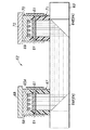
図9は、外筒部37と内筒部38及びコリメータレンズ39で構成した4芯用光コリメータ素子36を示し、コリメータレンズ39は一方を円弧状凸面40に他方を平坦面に形成した一体形レンズであり、内筒部38に形成した第1の光伝送路41に円弧状凸面40側を第2の光伝送路42に平坦面側を向けた状態で、外側縁部及び各円弧状凸面40の間が樹脂成形した内筒部38に、硬質材による外筒部37と共にインサートされている。
【0047】
図10は、外筒部43と内筒部44及びコリメータレンズ45で構成した別の実施形態による4芯用光コリメータ素子42を示し、コリメータレンズ45は一方を円弧状凸面46に他方を平坦面に形成した一体形レンズであり、内筒部44に形成した第1の光伝送路47に円弧状凸面46側を第2の光伝送路48に平坦面側を向けた状態で、外側縁部が樹脂成形した内筒部44に、硬質材による外筒部43と共にインサートされている。
【0048】
これら4芯用光コリメータ素子36,42は、単芯用光コリメータ素子10及び2芯用光コリメータ素子23の場合と同様に、フェルールや光半導体素子その他の光学部品と共に連結用筒状部材内に装着し、光軸の調芯を自動的に行うことができる4芯の光コリメータモジュールを構成することが可能であり、同様の構造及び製造方法によって、他の多芯用光コリメータ素子及び多芯の光コリメータモジュールを造ることができる。
【0049】
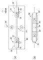
次に、図11では先の単芯用の光コリメータモジュール20を用いた光学機能モジュール49,52を説明するが、図11(a)の光学機能モジュール49は基板50上に左右一対の光コリメータモジュール20,20を配置すると共に、各光コリメータモジュール20,20間には、例えば光フィルタ又は光アッテネータ或いは光スイッチなどの光学部品51を配置している。
【0050】
この光学機能モジュール49は、一方側の光コリメータモジュール20のフェルール19に装着された光ファイバに光信号を入射させると、この光信号を光コリメータ素子10で平行光束に変換して光学部品51で制御された後に、他方側の光コリメータモジュール20に光伝送され、光コリメータ素子10で集光した後にフェルール19に装着された光ファイバによって光伝送される。
【0051】
この光学機能モジュール49では、各光コリメータモジュール20の光コリメータ素子10とフェルール19とは、連結用筒状部材18によって光軸が調芯されているので、従来技術による図1のように調芯作業を行う必要が無く、光学部品51と各光コリメータモジュール20との間の調芯作業のみを行った後に基板50に固定すれば良いので、調芯作業を容易且つ正確に行うことができる。
【0052】
特に、連結用筒状部材18として例えばステンレスパイプなどの金属製のものを用いると、レーザーなどのスポット溶接によって容易に固定することが可能であり、この連結用筒状部材18は各構成部材を保持すると共に、少なくとも基板50に設置する部分のみを正確に位置決めできれば良いので、円筒や角筒に限らず一部が欠落した筒状体でも良い。
【0053】
また、図11(b)の実施形態による光学機能モジュール52では、各光コリメータモジュール20と同様に、光学部品54を連結用筒状部材に装着して一体化した光学部品モジュール55に形成し、この光学部品モジュール55を各光コリメータモジュール20と共に長尺の連結用筒状部材53内に装着することによって、調芯作業を全く必要としない構造にしている。
【0054】
次に、図12〜14は多芯用光コリメータ素子(図示は、4芯用光コリメータ素子42)を用いた更に別の実施形態による光学機能モジュールを示し、図12の光学機能モジュール56は、長尺の連結用筒状部材57内に各コリメータ素子42を対向状に装着すると共に、その両側に4個の半導体発光素子又は半導体受光素子による半導体光学素子59を内蔵した半導体モジュール60と4芯用のフェルール58とを装着し、光軸の調芯作業を不要にしている。
【0055】
また、図13の光学機能モジュールは、4個の半導体発光素子59Aを内蔵した半導体モジュール60Aとコリメータ素子42を連結用筒状部材61で連結すると共に、4個の半導体受光素子59Bを内蔵した半導体モジュール60Bとコリメータ素子42を連結用筒状部材61で連結し、両者を離間した状態で配置して光信号を空間伝送する実施形態である。
【0056】
さらに、図14の光学機能モジュール62は、半導体発光素子65を内蔵した半導体モジュール66とコリメータ素子67及び半導体チップ68を一体に連結した発光側と、半導体受光素子69を内蔵した半導体モジュール70とコリメータ素子71及び半導体チップ72を一体に連結した受光側との間に、45度の反射面を備えた一対の反射鏡64(64A,64B)を基板63上に設け、光信号を空間伝送する実施形態であり、各反射鏡64の間には図11と同様の光学部品51を装着するの実施形態を採ることも可能である。
【図面の簡単な説明】
【図1】従来技術を適用した実施形態による光学機能モジュールを示す。
【図2】本発明を適用した実施形態の光コリメータ素子を示す。
【図3】本発明を適用した実施形態による光コリメータ素子の製造方法であって、外筒部とコリメータレンズをインサートして図2の光コリメータ素子の内筒部を射出成形する工程を示す。
【図4】本発明を適用した実施形態による光コリメータ素子の製造方法であって、インサートした外筒部とコリメータレンズを射出成形した内筒部によって一体化した図2の光コリメータ素子を示す。
【図5】本発明を適用した実施形態の光コリメータモジュールの製造方法であって、図2の光コリメータ素子を用いた光コリメータモジュールの製造方法を示す。
【図6】本発明を適用した実施形態の光コリメータモジュールであって、図2の光コリメータ素子を用いた光コリメータモジュールを示す。
【図7】本発明を適用した実施形態による光コリメータ素子であって、(a)は2芯光コリメータ素子の正面図を(b)は縦断面図を示す。
【図8】本発明を適用した実施形態の光コリメータモジュールの製造方法であって、図7の光コリメータ素子を用いた光コリメータモジュールの縦断面図を示す。
【図9】本発明を適用した実施形態による光コリメータ素子であって、(a)は4芯光コリメータ素子の正面図を(b)は縦断面図を示す。
【図10】本発明を適用した実施形態による光コリメータ素子であって、(a)は他の4芯光コリメータ素子の正面図を(b)は縦断面図を示す。
【図11】本発明の光コリメータモジュールを用いた実施形態の光学機能モジュールであって、(a)は分散配置した光学機能モジュールを、(b)は一体化した光学機能モジュールを示す。
【図12】本発明の光コリメータモジュールを用いた他の実施形態による一体化した光学機能モジュールの縦断面図を示す。
【図13】本発明の光コリメータモジュールを用いた他の実施形態による分散配置した光学機能モジュールの縦断面図を示す。
【図14】本発明の光コリメータモジュールを用いた更に他の実施形態による分散配置した光学機能モジュールの縦断面図を示す。
【符号の説明】
10,23,36,42,67,71 光コリメータ素子
11,24,37,43 外筒部
12,25,38,44 内筒部
13,26,39,45 コリメータレンズ
14,27,41,47 第1の光伝送路
15,28,42,48 第2の光伝送路
16 射出成形金型
17 樹脂成形部
18 連結用筒状部材
19,31,58 フェルール
20,29 光コリメータモジュール
21,34 ファイバ芯線
22 光信号
30,53,57,61 連結用筒状部材
32 係止突起
33 係止凹溝
35 インサートパイプ
40 円弧状凸面
46 円弧状凸面
49,52,62 光学機能モジュール
50,63 基板
51,54 光学部品
52,56 光学機能モジュール
55 光学部品モジュール
59 半導体光学素子
60,66,70 半導体モジュール
64 反射鏡
65 半導体発光素子
68,72 半導体チップ
69 半導体受光素子[0001]
TECHNICAL FIELD OF THE INVENTION
The present invention relates to an optical collimator element that converts an optical signal to be transmitted into a parallel light beam, a method of manufacturing the same, and an optical collimator module in which an optical semiconductor element, a ferrule, and other optical component elements are coupled to the optical collimator element. It can be used in technical fields such as pickups.
[0002]
[Prior art]
This type of optical collimator module converts an optical signal emitted from a semiconductor light emitting element such as a laser diode into a parallel light beam with a collimator lens and transmits the parallel light beam, or converts a parallel light beam transmitted through the optical fiber into an optical signal. It is used when the light is condensed by a collimator lens and is incident on a semiconductor light receiving element such as a photodiode, or when an optical signal is transmitted and received between a semiconductor light emitting element and a semiconductor light receiving element with a collimator lens interposed therebetween. ing.
[0003]
Optical collimator modules used in these applications must be able to easily and accurately align the optical axis of the collimator lens with the optical semiconductor element, ferrule, and other optical components in order to reduce transmission loss and other performance degradation. , A structure that allows easy and quick connection work in the field, that mass production is possible in order to reduce the manufacturing cost, multi-core and small diameter optical fibers due to the increase in the amount of information, It is required to be compatible with both single-core and multi-core.
[0004]
FIG. 1 shows an example of an optical function module 1 according to the prior art. Ferrules 3 and 4 having optical fibers 3a and 4a mounted at symmetric positions on the left and right, and collimator lenses 5a and 5 as optical elements on a substrate 2. Along with the lens units 5 and 6 equipped with 6a, an optical component unit 7 equipped with an optical component 7a such as an optical filter, an optical attenuator, or an optical switch is arranged in the center.
[0005]
In this optical function module 1, an optical signal transmitted by one of the optical fibers 3a (4a) is emitted to the collimator lens 5a (6a) via the ferrule 3 (4) and is parallelized by the collimator lens 5a (6a). After being converted into a light beam 8 and undergoing control such as filtering, attenuation, or switching when passing through an optical circuit component 7a, the light is condensed by a collimator lens 6a (5a), and the other is passed through a ferrule 4 (3). Incident on the optical fiber 4a (3a).
[0006]
The optical function module 1 performs alignment work for aligning the optical axes between the optical elements using an optical axis adjusting device, and positions the optical components at predetermined positions. Although it is fixed by welding means, it is necessary to use expensive equipment to accurately align the optical axis, and it is difficult to reduce the cost by taking a lot of time. Conversion was also difficult.
[0007]
Various proposals have been made to improve the optical axis alignment work and the like according to the prior art, including, for example, the inventions disclosed in Patent Literature 1 and Patent Literature 2, but there is a need for an optical collimator module. The above-mentioned requirements cannot be sufficiently satisfied, and the following problems that need to be solved remain.
Patent Document 1: JP-A-11-54849
Patent Document 2: JP-A-2001-343556
[0008]
Patent Document 1 discloses a method of insert molding a ball lens using a resin to form a primary molded piece for holding the ball lens, and then insert molding the primary molded piece using a resin to mount an optical semiconductor element mounting portion and a receptacle bore. There is disclosed a method for manufacturing an optical module for secondary molding of a resin housing having the following.
[0009]
The optical module manufactured by the manufacturing method of Patent Document 1 can fix a lens to a resin housing without using a resin adhesive or the like, can be mass-produced at low cost, and has the conventional technology of FIG. As compared with the case where the ferrule and the lens unit are separated from each other, there is a possibility that the alignment operation can be performed easily.
[0010]
Patent Literature 2 discloses an optical fiber holding unit that holds an optical fiber in a plurality of optical fiber holding holes, and an optical component holding unit that holds an optical component (spherical lens) in a plurality of optical component holding holes. A multi-core optical collimator element for providing a guide hole in an exposed end face, fitting a guide pin in the guide hole and positioning the same, and optically coupling a plurality of optical fibers and optical components in a state where both end exposed faces are surface-joined. Is disclosed.
[0011]
The multi-core optical collimator element of Patent Literature 2 has a shorter assembling time and a smaller size than a ferrule type in which a sleeve is used for connection and welding between the sleeve and the V-groove in which processing of the V-groove is difficult. The processing cost can be reduced as compared with the method, and in particular, by holding the optical component by elastically deforming the optical component holding portion, it is possible to stably hold an optical component having a variation in dimensions.
[0012]
[Problems to be solved by the invention]
However, in the case of manufacturing by primary and secondary insert molding as in Patent Literature 1, it is difficult to reduce the size because the outer diameter becomes thick, and heat shrinkage occurs after each insert molding. Therefore, dimensional accuracy such as inner and outer diameters, coaxiality, and roundness may be reduced.
[0013]
Further, as in Patent Literature 2, when a guide pin is fitted into a guide hole provided inside the outer diameter to connect each holding portion, it is necessary to connect at least two places so as not to rotate, For this reason, it is difficult to reduce the size because the outer diameter becomes thick, and the optical axis may be displaced unless the two guide holes are positioned with high precision during manufacture.
[0014]
Further, when an optical component (spherical lens) is held in an optical component holding hole as in Patent Document 2, if the optical component is press-fitted from an end of the holding hole, it is extremely difficult to insert and position the optical component. In addition, usable lenses are limited to ball lenses or rod lenses, and if the optical component holding part is elastically deformed to hold the optical component, there is a possibility that the optical axis may be displaced or use in a place where there is vibration. Have difficulty.
[0015]
The present invention provides an optical collimator element, a method of manufacturing the same, and an optical collimator module that can solve the above-described problems of the related art. Particularly, an optical semiconductor element, a ferrule, and other optical components are highly precisely aligned. Inexpensive optical collimator element that can be coupled in a state and a method of manufacturing the same, and an optical collimator in which other optical components including an optical semiconductor element and an optical fiber mounted ferrule are coupled to the optical collimator element in an aligned state Its main purpose is to provide modules.
[0016]
[Means for Solving the Problems]
In the optical collimator element according to the present invention, the outer shape of the inner cylindrical portion having the optical transmission path formed therein is retained by the outer cylindrical portion made of a hard material, and at least the outer edge of the optical transmission path is embedded in the inner cylindrical portion. A collimator lens is provided, the outer cylinder and the collimator lens are inserted, and the inner cylinder is integrally formed of a resin material.
[0017]
In this optical collimator element, the inserted outer cylinder and the collimator lens are firmly joined together via the injection-molded inner cylinder. In particular, the outer diameter is maintained by the outer cylinder made of a hard material. The dimensional accuracy and concentricity can be made high, and the collimator lens has durability against shock and vibration because the outer edge is mounted by being embedded in the inner cylindrical portion made of a molded resin material.
[0018]
A method for manufacturing an optical collimator element according to the present invention is a method for manufacturing an optical collimator element according to claim 1, wherein an outer cylindrical portion of a collimator lens and a hard material is provided in an injection mold having an upper mold and a lower mold. And insert the core pins that form the optical transmission path from the upper mold and the lower mold, respectively, to clamp the collimator lens at the tip, and between the upper mold and the lower mold and the upper and lower ends of the outer cylinder. Provide an inflow port and an outflow port of the molding resin material, fill the molding resin material into the cavity formed by the upper and lower dies and the outer cylinder portion, and bury the outer edge portion of the collimator lens in the inner cylinder portion. Integrally molded.
[0019]
In the method of manufacturing the optical collimator element, since the outer cylinder and the collimator lens are injection-molded as insert parts, mass production can be performed at low cost, and the centering of the collimator lens with respect to the outer cylinder and the inner cylinder can be performed. Since the positioning of the collimator lens is performed in the injection mold, a highly accurate optical collimator element can be easily manufactured.
[0020]
An optical collimator module according to the present invention mounts the optical collimator element according to claim 1 inside the connecting tubular member and at least one of an optical semiconductor element, a ferrule having an optical fiber mounted thereon, and other optical components. Is mounted, and the optical axis is aligned by butt-joining the end face to the optical collimator element.
[0021]
In this optical collimator module, the optical axis can be aligned without performing any special alignment work by simply mounting the optical collimator element, the optical semiconductor element, the ferrule, and the like on the connecting tubular member, and the optical axis can be set as desired. It is possible to attach and use the optical components described above in a detachable manner, and when the outer cylindrical portion and the connecting cylindrical member are made of metal, they can be fixed at the alignment position by welding means.
[0022]
Further, the optical collimator element and the optical collimator module according to the present invention have a simple structure, can be easily adapted to both single-core and multi-core, and can be easily reduced in size. Existing ferrules made of zirconia can be used.
[0023]
BEST MODE FOR CARRYING OUT THE INVENTION
Hereinafter, an optical collimator element, a method of manufacturing the same, and an optical collimator module of the present invention will be described in detail based on an embodiment of the accompanying drawings to which the present invention is applied. FIG. 3 and FIG. 4 are explanatory diagrams of a method of manufacturing the optical collimator element of FIG.
[0024]
The optical collimator element 10 includes an outer cylindrical portion 11 made of a hard material, an inner cylindrical portion 12 made of a resin material integrally formed in the outer cylindrical portion 11, and a shaft having an outer edge embedded inside the inner cylindrical portion 12. The first and second optical transmission paths 14 and 15 formed before and after the collimator lens 13 by the inner side of the inner cylindrical portion 12 are provided at the axis center. I have.
[0025]
The outer cylindrical portion 11 enhances the dimensional accuracy of the outer diameter of the optical collimator element 10 and the concentricity with respect to the axis, reinforces the inner cylindrical portion 12 with a resin material, and connects a connecting cylindrical member such as a sleeve on the outer periphery as described later. It has a function to make it slidable by attaching to it, and heat resistance and corrosion resistance are also necessary.For example, it is desirable to use hard metal material such as stainless steel or zirconia. Although a possible stainless steel material is used, another hard material may be used as long as it satisfies the above function.
[0026]
The shape of the outer cylinder portion 11 is cylindrical in the illustrated embodiment. However, the shape is not limited to the cylindrical shape, and may be rectangular or any other shape as desired. The length of the portion 11 is made shorter so that the inner cylinder portion 12 is exposed at both ends so that the inner cylinder portion 12 can be locked in the axial direction. It is also possible to adopt a mode in which a locking projection is provided on the inner surface of the outer tube portion 11 with respect to the outer surface of the inner tube portion 12.
[0027]
In particular, according to the embodiment shown in the drawings, it is easy to finish the end face in order to improve the accuracy of abutment with the optical element on the other side. In addition, the end of the resin material is less likely to damage the inner surface of the connecting tubular body than the hard material such as metal, and it is easy to chamfer the outer periphery on the tip side to facilitate insertion. This is more desirable in that it is easy to perform injection molding in which an outer tube described later is inserted.
[0028]
The inner cylindrical portion 12 has a function of integrating the outer cylindrical portion 11 and the collimator lens 13 by insert molding, and forming the first and second optical transmission paths 14 and 15 at the axis. Since optical signals are transmitted and received to and from the optical elements coupled to both ends of the optical transmission line 1 via the optical transmission lines 14 and 15, the cross-sectional shape of the optical transmission lines 14 and 15 is not limited to a cylindrical shape. Various cross-sectional shapes can be adopted within a range that does not hinder the transmission of light.
[0029]
The molding resin material of the inner cylinder portion 12 is a desired machine from various thermoplastic resin materials, preferably engineering plastics such as liquid crystal polymer, polyetheretherketone (PEEK material) or polyphenylsulfide (PPS). Injection molding can be performed by selecting a molding resin material that can obtain the appropriate strength and dimensional accuracy.However, in the illustrated embodiment, the liquid crystal polymer is particularly used because the thermal expansion coefficient is close to that of stainless steel and the workability is good. I'm using
[0030]
As the collimator lens 13, a glass ball lens is used in the illustrated embodiment, but a rod lens or an aspherical lens can be used as long as it has a collimating function. It is also possible to insert and use a lens made of resin (mold lens).
[0031]
In this optical collimator element 10, an inserted outer cylindrical portion 11 and a collimator lens 13 are firmly joined together via an injection-molded inner cylindrical portion 12, and the outer diameter is particularly maintained by the outer cylindrical portion 11 made of a hard material. The outer diameter and the concentricity can be made high accuracy by being shaped, and the collimator lens 13 is mounted with the outer edge buried in the inner cylinder 12 made of a molded resin material, so that it is resistant to shock and vibration. It is durable.
[0032]
As shown in FIG. 3, the optical collimator element 10 is manufactured by mounting an outer cylinder 11 made of a stainless steel pipe and a collimator lens 13 made of a spherical lens as insert parts in an injection mold 16 having an upper mold 16A and a lower mold 16B. However, core pins A1 and B1 forming the optical transmission paths 14 and 15 are protruded from the upper mold 16A and the lower mold 16B, and the collimator lens 13 is held between the ends of the core pins A1 and B1.
[0033]
Further, an inlet D1 and an outlet D2 of a molding resin material are provided between the upper die 16A and the lower die 16B and the upper and lower ends of the outer cylindrical portion 11, and the upper die 16A, the lower die 16B and the outer cylindrical portion 11 When the molding resin material of the liquid crystal polymer flows into the enclosed cavity C from the inflow port D1 and flows out from the outflow port D2 as shown by an arrow, the inner cylindrical portion 12 is inserted into the cavity C as shown in FIG. Is formed.
[0034]
After the injection molding, the upper mold 16A and the lower mold 16B are released, the resin molded part 17 is taken out of the injection molding die 16, and unnecessary resin molded parts 17a to 17d of the resin molded part 17 are removed. When the finishing process of the inner cylindrical portion 12 is performed by polishing or the like so that the outer diameters of both ends of the forming portion 17 are flush with the outer diameter of the outer cylindrical portion 11, the optical collimator element 10 shown in FIG. it can.
[0035]
In the method of manufacturing the optical collimator element 10, since the outer cylinder 11 and the collimator lens 13 are injection-molded as insert parts, mass production can be performed at low cost, and the centering of the collimator lens 13 with respect to the outer cylinder 11 and Since the positioning of the collimator lens 13 with respect to the inner cylindrical portion 12 is performed in the injection mold 16, the highly accurate optical collimator element 10 can be easily manufactured.
[0036]
In particular, the inserted collimator lens 13 is sandwiched between the core pins A1 and B1 provided on the upper mold 16A and the lower mold 16B, and the outer edge is formed on the resin molded part 17 forming the inner cylinder part 12 in a state of being accurately positioned. Since they are buried, they are mounted in the optical collimator element 10 in a stable state without being displaced by vibration or shock, and the optical transmission paths 14 and 15 are formed by the core pins A1 and B1 holding the collimator lens 13 therebetween. Can be easily formed.
[0037]
The optical collimator element 10 can be connected to an optical semiconductor element, a ferrule, and other optical components to constitute an optical collimator module that does not require alignment of the optical axis. For example, the optical collimator module shown in FIGS. In the embodiment, an optical collimator module 20 connected to a ferrule 19 via a connecting tubular member 18 is shown.
[0038]
The optical collimator module 20 inserts the optical collimator element 10 from one end of the connecting tubular member 18 to the end on the optical transmission path 15 side, and inserts the ferrule 19 from the other end of the connecting tubular member 18. Is inserted, and the tip side of the optical collimator element 10 and the tip side of the ferrule 19 are abutted, and they are connected with their optical axes aligned.
[0039]
As a result, the optical signal 22 emitted from the fiber core 21 attached to the ferrule 19 to the optical transmission line 15 is converted into a parallel light beam by the collimator lens 13, and is then transmitted to the outside of the optical collimator module 20 via the optical transmission line 14. The optical signal 22 is transmitted to the collimator lens 13 from the outside via the optical transmission path 14, and is converged on the fiber core wire 21 and transmitted from the optical fiber 19 to the outside of the optical collimator module 20. You.
[0040]
In this optical collimator module 20, the optical axis can be aligned without specially performing the alignment work by simply mounting the optical collimator element 10 and the ferrule 19 on the connecting tubular member 18, and the ferrule 19 to be used can be used. Various known ferrules including a zirconia ferrule at the tip can be used. In the illustrated embodiment, a resin ferrule in which a stainless steel pipe 22 is insert-molded is mounted on the outer periphery.
[0041]
The connecting tubular member 18 may be a cylindrical split sleeve or a non-split cylindrical sleeve conventionally used for connecting optical fibers to each other via a ferrule. The material of the connecting tubular member 18 can be made of zirconia, stainless steel, hard resin, or the like. Particularly, when the optical collimator module is used by welding to a substrate. Is desirably a metal sleeve such as stainless steel.
[0042]
Next, an embodiment of an optical collimator element to which a multi-core ferrule having two or more cores and an optical collimator module will be described with reference to FIGS. 7 to 10. The two-core optical collimator element 23 shown in FIG. The two-core optical collimator element 23 is composed of a portion 24, an inner cylindrical portion 25, and a collimator lens 26. For example, an optical collimator module 29 as shown in FIG. 8 can be manufactured.
[0043]
The same material as that of the single-core optical collimator element 10 shown in FIG. 2 is used for the two-core optical collimator element 23, and the outer cylindrical part 24 and the collimator lens 26 are inserted in the same manner as in FIGS. The inner cylinder part 25 can be injection-molded, but differs from the optical collimator element 10 in that two collimator lenses 26A and 26B are mounted in the inner cylinder part 25 and that each collimator lens 26 The first and second optical transmission paths 27 and 28 are arranged before and after.
[0044]
When the ferrule 31 with the insert pipe 35 and the two-core optical collimator element 23 are inserted into the connecting tubular member 30 as in the optical collimator module 20 shown in FIGS. The line 34 and the optical axis of the collimator lens 26 can be aligned and connected in an aligned state. However, unlike the case of a single core, in order to make the respective optical axes coincide with each other, positioning means for the rotation direction is required.
[0045]
In the embodiment shown in FIG. 8, the positioning means is provided with two locking projections 32 at the tip of the optical collimator element 23 and two locking recesses 33 at the tip of the ferrule 31 for fitting and locking. However, the locking projection 32 and the locking groove 33 may be provided in one place, and a configuration in which the locking projection 32 and the locking groove 33 are reversed may be adopted.
[0046]
FIG. 9 shows a four-core optical collimator element 36 composed of an outer cylindrical part 37, an inner cylindrical part 38, and a collimator lens 39. One of the collimator lenses 39 is formed as an arc-shaped convex surface 40 and the other as a flat surface. A lens having an outer edge portion and each arc-shaped convex surface with the arc-shaped convex surface 40 facing the first optical transmission line 41 formed on the inner cylindrical portion 38 and the flat surface side facing the second optical transmission line 42; The space between the inserts 40 is inserted into the resin-molded inner cylinder 38 together with the outer cylinder 37 made of a hard material.
[0047]
FIG. 10 shows a four-core optical collimator element 42 according to another embodiment composed of an outer cylindrical portion 43, an inner cylindrical portion 44, and a collimator lens 45. One of the collimator lenses 45 is an arc-shaped convex surface 46 and the other is a flat surface. And an outer edge portion with the arc-shaped convex surface 46 facing the first optical transmission path 47 formed on the inner cylindrical portion 44 and the flat surface side facing the second optical transmission path 48. Are inserted together with the outer cylindrical portion 43 made of a hard material into the resin-molded inner cylindrical portion 44.
[0048]
The four-core optical collimator elements 36 and 42 are provided together with a ferrule, an optical semiconductor element, and other optical components in the connecting tubular member, similarly to the single-core optical collimator element 10 and the two-core optical collimator element 23. It is possible to configure a four-core optical collimator module that can be mounted and automatically adjust the optical axis, and with the same structure and manufacturing method, other multi-core optical collimator elements and multiple cores Can be manufactured.
[0049]
Next, the optical function modules 49 and 52 using the single-core optical collimator module 20 will be described with reference to FIG. 11, but the optical function module 49 in FIG. The modules 20 are arranged, and an optical component 51 such as an optical filter, an optical attenuator, or an optical switch is arranged between the optical collimator modules 20.
[0050]
When an optical signal is incident on an optical fiber attached to the ferrule 19 of the optical collimator module 20 on one side, the optical function module 49 converts the optical signal into a parallel light flux by the optical collimator element 10 and converts the optical signal by the optical component 51. After being controlled, the light is transmitted to the optical collimator module 20 on the other side, condensed by the optical collimator element 10, and then transmitted by the optical fiber mounted on the ferrule 19.
[0051]
In this optical function module 49, since the optical axis of the optical collimator element 10 and the ferrule 19 of each optical collimator module 20 is aligned by the connecting tubular member 18, as shown in FIG. There is no need to perform any work, and only the alignment work between the optical component 51 and each of the optical collimator modules 20 needs to be performed and then fixed to the substrate 50, so that the work can be easily and accurately performed.
[0052]
In particular, when a metal member such as a stainless steel pipe is used as the connecting tubular member 18, it is possible to easily fix the connecting tubular member 18 by spot welding such as laser. It is only necessary to be able to hold and at least accurately position at least a portion to be installed on the substrate 50. Therefore, the present invention is not limited to a cylinder or a square tube, and may be a cylindrical body with a part missing.
[0053]
In addition, in the optical function module 52 according to the embodiment of FIG. 11B, similarly to each optical collimator module 20, the optical component 54 is mounted on the connecting tubular member to form an integrated optical component module 55, By mounting the optical component module 55 together with the respective optical collimator modules 20 in the long connecting tubular member 53, a structure that does not require any alignment work is achieved.
[0054]
Next, FIGS. 12 to 14 show an optical function module according to still another embodiment using a multi-core optical collimator element (four-core optical collimator element 42 in the drawing), and the optical function module 56 of FIG. A semiconductor module 60 having four semiconductor light-emitting elements or semiconductor optical elements 59 formed of semiconductor light-receiving elements on both sides thereof and a four-core semiconductor module 60 in which the respective collimator elements 42 are mounted facing each other in a long connecting tubular member 57. A ferrule 58 for the optical axis is attached, and the work of aligning the optical axis becomes unnecessary.
[0055]
In the optical function module of FIG. 13, a semiconductor module 60A having four built-in semiconductor light emitting elements 59A and a collimator element 42 are connected by a connecting tubular member 61, and a semiconductor having four semiconductor light receiving elements 59B built therein. This is an embodiment in which the module 60B and the collimator element 42 are connected by a connecting tubular member 61, and both are arranged in a separated state to spatially transmit an optical signal.
[0056]
Further, the optical function module 62 of FIG. 14 includes a semiconductor module 66 having a built-in semiconductor light-emitting element 65, a collimator element 67, and a light-emitting side in which a semiconductor chip 68 is integrally connected. A pair of reflecting mirrors 64 (64A, 64B) having a 45-degree reflecting surface are provided on a substrate 63 between the device 71 and a light receiving side where the semiconductor chip 72 is integrally connected, and an optical signal is spatially transmitted. It is also possible to adopt an embodiment in which the same optical components 51 as in FIG.
[Brief description of the drawings]
FIG. 1 shows an optical function module according to an embodiment to which the related art is applied.
FIG. 2 shows an optical collimator element according to an embodiment to which the present invention is applied.
FIG. 3 shows a method of manufacturing an optical collimator element according to an embodiment to which the present invention is applied, and shows a step of injection molding an inner cylindrical part of the optical collimator element of FIG. 2 by inserting an outer cylindrical part and a collimator lens.
4 is a method for manufacturing an optical collimator element according to an embodiment to which the present invention is applied, and shows the optical collimator element of FIG. 2 in which an inserted outer cylindrical part and an inner cylindrical part obtained by injection-molding a collimator lens are integrated.
FIG. 5 shows a method for manufacturing an optical collimator module according to an embodiment to which the present invention is applied, and shows a method for manufacturing an optical collimator module using the optical collimator element of FIG.
FIG. 6 shows an optical collimator module according to an embodiment to which the present invention is applied, which uses the optical collimator element of FIG. 2;
7A and 7B are optical collimator elements according to an embodiment to which the present invention is applied, wherein FIG. 7A is a front view of a two-core optical collimator element, and FIG.
8 is a longitudinal sectional view of an optical collimator module using the optical collimator element of FIG. 7 in a method of manufacturing an optical collimator module according to an embodiment to which the present invention is applied.
9A and 9B are optical collimator elements according to an embodiment to which the present invention is applied, wherein FIG. 9A is a front view of a four-core optical collimator element, and FIG. 9B is a longitudinal sectional view.
10A and 10B are optical collimator elements according to an embodiment to which the present invention is applied, wherein FIG. 10A is a front view of another four-core optical collimator element and FIG. 10B is a longitudinal sectional view.
11A and 11B are optical function modules according to an embodiment using the optical collimator module of the present invention, wherein FIG. 11A shows an optical function module arranged in a distributed manner, and FIG. 11B shows an integrated optical function module.
FIG. 12 is a longitudinal sectional view of an integrated optical function module according to another embodiment using the optical collimator module of the present invention.
FIG. 13 is a longitudinal sectional view of a distributed optical function module according to another embodiment using the optical collimator module of the present invention.
FIG. 14 is a longitudinal sectional view of a distributed optical function module according to still another embodiment using the optical collimator module of the present invention.
[Explanation of symbols]
10,23,36,42,67,71 Optical collimator element
11, 24, 37, 43 Outer cylinder
12, 25, 38, 44 Inner cylinder
13,26,39,45 Collimator lens
14, 27, 41, 47 First optical transmission line
15, 28, 42, 48 Second optical transmission line
16 Injection mold
17 Resin molding
18 Connecting tubular member
19,31,58 Ferrule
20,29 Optical collimator module
21,34 fiber core wire
22 Optical signal
30,53,57,61 Connecting tubular member
32 locking projection
33 locking groove
35 Insert Pipe
40 arc-shaped convex surface
46 arc-shaped convex surface
49, 52, 62 Optical function module
50, 63 substrate
51,54 Optical parts
52,56 Optical function module
55 Optical Component Module
59 Semiconductor optical element
60, 66, 70 semiconductor module
64 reflector
65 Semiconductor light emitting device
68,72 Semiconductor chip
69 Semiconductor photo detector