JP2004239799A - Rotation angle detecting device - Google Patents
Rotation angle detecting device Download PDFInfo
- Publication number
- JP2004239799A JP2004239799A JP2003030407A JP2003030407A JP2004239799A JP 2004239799 A JP2004239799 A JP 2004239799A JP 2003030407 A JP2003030407 A JP 2003030407A JP 2003030407 A JP2003030407 A JP 2003030407A JP 2004239799 A JP2004239799 A JP 2004239799A
- Authority
- JP
- Japan
- Prior art keywords
- rotation angle
- magnet
- magnetic
- outer peripheral
- detecting device
- Prior art date
- Legal status (The legal status is an assumption and is not a legal conclusion. Google has not performed a legal analysis and makes no representation as to the accuracy of the status listed.)
- Pending
Links
Images


Abstract
Description
【0001】
【発明の属する技術分野】
本発明は、被検出物の回転角度を検出する回転角検出装置に関し、特に、エンジンのスロットル弁開度の検出装置に適用して有効な技術に関する。
【0002】
【従来の技術】
従来より、非接触型の回転角検出装置として、例えば特許第2842482号公報のように、被検出物に磁石を取り付け、その磁束変化を捉えて被検出物の回転角度の検出を行うものが知られている。
【0003】
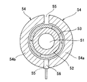
図12の回転角検出装置では、回転角度の検出が求められるシャフト51には磁性体からなるロータコア52が取り付けられる。ロータコア52の内周には、2極構成のリングマグネット53が固定される。リングマグネット53の外側には、シャフト51と同軸状にステータコア54が配置される。ステータコア54は磁性体にて形成され、断面半円形状の2個のコアピース54a,54bから構成される。コアピース54a,54bの間の間隙55にはホールIC56が配置されている。
【0004】
ステータコア54は、図12に示すように、リングマグネット53の磁束の磁路となっており、ホールIC56からは鎖交する磁束密度に応じた電圧信号が出力される。シャフト51と共にリングマグネット53が回転すると、ホールIC56を通過する磁束量が変化し、これに伴いホールIC56からの出力信号も変化する。この信号変化はシャフト51の回転角度と対応しており、その回転に伴ってほぼ直線的に変化する。これにより、ホールIC56からの信号に基づき、シャフト51の回転角度の検出が可能となる。
【0005】
一方、近年、自動車部品の電子化に伴い、エンジンのスロットル弁をモータにて駆動するいわゆる電子制御スロットル装置が広く用いられている。そこでは、従来のアクセルワイヤによる機械的動作に代えて、電気信号によってスロットル弁が制御される。アクセル踏み込み量はポテンショメータ等によって電気的に検出され、その値に応じてモータが駆動されてスロットル弁の開閉が行われる。
【0006】
このような電子制御スロットル装置では、スロットル弁の開度は、図12のような回転角検出装置によってが検出されるが、これ以外にもマグネットをステータコアの外側に配したアウタロータ型の検出装置も多く使用されている。例えば特開2001−208510号公報、特開2001−289610号公報等には、このようなアウタロータ型の装置が開示されている。そこでは、スロットル弁が固定されたシャフトがモータ駆動されると、ホールICの出力信号によって、シャフトの回転角度、すなわちスロットル弁の開度が検出される。そして、検出された弁開度に基づいてモータの動作制御が行われ、アクセル踏み込み量やエンジン負荷等に応じた弁開度が設定される。
【0007】
【特許文献1】特許第2842282号公報
【特許文献2】特開平8−35809号公報
【特許文献3】特開2001−4315号公報
【特許文献4】特開2001−59702号公報
【特許文献5】特開2001−188003号公報
【特許文献6】特開2001−208510号公報
【特許文献7】特開2001−289609号公報
【特許文献8】特開2001−289610号公報
【特許文献9】特開2001−303979号公報
【特許文献10】特開2001−317909号公報
【特許文献11】特願2002−211201号
【特許文献12】特願2002−257723号
【特許文献13】特願2002−258901号
【0008】
【発明が解決しようとする課題】
しかしながら、図12のような回転角検出装置では、図12に示すように、ステータコア54の全周が磁路となるため、シャフト51の回転抵抗(フリクショントルク)が大きくなるという問題があった。すなわち、ステータコア54とリングマグネット53の間には全周に亘って磁気的吸引力が発生するため、図12の回転角検出装置は、その分、シャフト51のフリクショントルクが大きくなる。フリクショントルクが大きくなると、シャフト駆動用のモータの出力も大きくしなければならず、モータの体格や価格、消費電流量が増大し好ましくない。
【0009】
また、図12の回転角検出装置では、軸方向に長いリングマグネット53を使用するため、磁石の使用量が多くコスト高になるという問題もあった。さらに、リングマグネット53やステータコア54を径方向にシャフト51と同心円状に配置する構成のため、装置全体の外径が大きくなりがちであり、レイアウト上の制約を受けるという問題もあった。
【0010】
本発明の目的は、フリクショントルクが少なく、レイアウト性に優れた低コストの回転角検出装置を提供することにある。
【0011】
【課題を解決するための手段】
本発明の回転角検出装置は、回転角度の検出が求められる被検出体に設けられた磁性体からなる作動部と、前記作動部に取り付けられた第1のマグネットと、前記第1のマグネットと軸方向に間隔をあけて前記作動部に取り付けられ、前記第1のマグネットとは異なる極性を有する第2のマグネットと、前記第1のマグネットの外側に配置され、前記第1のマグネットと間隔をあけて対向する対向面を備えてなる、磁性体にて形成された第1のステータ部材と、前記第1のステータ部材と軸方向に間隔をあけて配置され、前記第2のマグネットと間隔をあけて対向する対向面を備えてなる、磁性体にて形成された第2のステータ部材と、前記第1のマグネットから前記第1及び第2のステータ部材を介して前記第2のマグネットに至る磁路中に配置された磁気検出素子とを有することを特徴とする。
【0012】
本発明にあっては、第1及び第2のマグネットと、マグネットに対向する対向面を備えたステータ部材とによって磁路を形成しているので、作動部周囲の磁路を削減できマグネットと対向面との間に働く磁気的吸引力を低減できる。従って、被検出体の回転抵抗力を低減させることができる。また、被検出体の片側領域のみで回転角検出装置を構成することができるため、マグネット量の低減やレイアウト性の向上を図ることが可能となる。
【0013】
前記回転角検出装置において、前記第1及び第2のマグネットに断面が円弧形状となった外周面を形成し、前記第1及び第2のステータ部材の前記対向面をそれぞれ前記各外周面と略一定間隔をあけて対向させても良い。
【0014】
また、前記回転角検出装置において、前記第1及び第2のマグネットに断面が円弧形状となった外周面を形成すると共に、前記第1及び第2のステータ部材の前記対向面にそれぞれ、前記各外周面と略一定間隔をあけて対向する円弧部と、前記円弧部の端部に形成され末端に向けて前記各外周面との間隔が拡大する拡開部とを設けても良い。これにより、マグネットから作動部を介して対向面に至る磁路が形成されにくくなり、出力信号の曲線部分が減少し、磁気検出素子からより直線領域の広い信号出力を得ることが可能となる。
【0015】
本発明の他の回転角検出装置は、回転角度の検出が求められる被検出体に設けられた磁性体からなる作動部と、前記作動部に取り付けられたマグネットと、前記マグネットの外側に配置され、前記マグネットと間隔をあけて対向する対向面を備えてなる、磁性体にて形成された第1のステータ部材と、前記第1のステータ部材と軸方向に間隔をあけて配置され、前記作動部と間隔をあけて対向する対向面を備えてなる、磁性体にて形成された第2のステータ部材と、前記マグネットから前記第1及び第2のステータ部材と前記作動部を介して前記マグネットに至る磁路中に配置された磁気検出素子とを有することを特徴とする。
【0016】
本発明にあっては、マグネットと、マグネットや作動部に対向する対向面を備えたステータ部材によって磁路を形成しているので、作動部周囲の磁路を削減できマグネットと対向面との間に働く磁気的吸引力を低減できる。従って、被検出体の回転抵抗力を低減させることができる。また、被検出体の片側領域のみで回転角検出装置を構成することが可能となるため、レイアウト性も向上する。さらに、マグネット1個にて磁路が形成されるので、マグネット使用量の更なる削減が可能となる。
【0017】
前記回転角検出装置において、前記マグネットに断面が円弧形状となった外周面を形成し、前記第1のステータ部材の前記対向面を前記外周面と略一定間隔をあけて対向させると共に、前記第2のステータ部材の前記対向面を前記作動部と略一定間隔をあけて対向させても良い。
【0018】
また、前記回転角検出装置において、前記マグネットに断面が円弧形状となった外周面を形成すると共に、前記第1のステータ部材の前記対向面に、前記外周面と略一定間隔をあけて対向する円弧部と、前記円弧部の端部に形成され末端に向けて前記各外周面との間隔が拡大する拡開部とを設けても良い。これにより、マグネットから作動部を介して対向面に至る磁路が形成されにくくなり、出力信号の曲線部分が減少し、磁気検出素子からより直線領域の広い信号出力を得ることが可能となる。
【0019】
さらに、前記回転角検出装置において、前記マグネットを前記外周面の中心角が略180°に形成された半円筒形状に形成しても良い。このように、半円筒形等、部分円弧断面の外周面を有するマグネットを用いることにより、円形断面を有するリングマグネットに対し、磁石使用量を半減させることができる
【0020】
一方、本発明の他の回転角検出装置は、回転角度の検出が求められる被検出体に設けられた磁性体からなる作動部と、前記作動部に取り付けられ、軸方向に隣接して第1及び第2の磁極層が形成されたマグネットと、前記第1の磁極層の外側に配置され、前記第1の磁極層と間隔をあけて対向する対向面を備えてなる、磁性体にて形成された第1のステータ部材と、前記第1のステータ部材と軸方向に間隔をあけて配置され、前記第2の磁極層と間隔をあけて対向する対向面を備えてなる、磁性体にて形成された第2のステータ部材と、前記第1の磁極層から前記第1及び第2のステータ部材を介して前記第2の磁極層に至る磁路中に配置された磁気検出素子とを有することを特徴とする。
【0021】
本発明にあっては、第1及び第2の磁極層と、各磁極層に対向する対向面を備えたステータ部材とによって磁路を形成しているので、作動部周囲の磁路を削減できマグネットと対向面との間に働く磁気的吸引力を低減できる。従って、被検出体の回転抵抗力を低減させることができる。また、被検出体の片側領域のみで回転角検出装置を構成することができると共に、1個の磁石に複数の磁極層を設けたので軸方向の寸法を短縮できレイアウト性も向上する。
【0022】
前記回転角検出装置において、前記マグネットに断面が円形となった外周面を形成し、前記第1及び第2のステータ部材の前記対向面をそれぞれ前記各外周面と略一定間隔をあけて対向させても良い。
【0023】
また、前記回転角検出装置において、前記マグネットに断面が円弧形状となった外周面を形成すると共に、前記第1及び第2のステータ部材の前記対向面にそれぞれ、前記外周面と略一定間隔をあけて対向する円弧部と、前記円弧部の端部に形成され末端に向けて前記外周面との間隔が拡大する拡開部とを設けても良い。これにより、マグネットから作動部を介して対向面に至る磁路が形成されにくくなり、出力信号の曲線部分が減少し、磁気検出素子からより直線領域の広い信号出力を得ることが可能となる。
【0024】
さらに、回転角検出装置において、前記第1及び第2の磁極層を、互いに隣接する磁極の極性を異にする1又は2極の磁極をそれぞれ有する構成としても良い。
【0025】
加えて、前記回転角検出装置において、前記磁気検出素子を前記第1及び第2のステータ部材の間に配置しても良く、前記第1及び第2のステータ部材の間に非磁性体からなる支持部材を設けても良い。
【0026】
さらに、前記回転角検出装置において、前記第1又は第2のステータ部材の少なくとも一方に、軸方向に沿って延びその先端部が前記磁気検出素子と対向する、磁性体にて形成されたポール部材を設けても良い。これにより、マグネットの磁束を効率良く磁気検出素子に導くことができ、磁束変化の検出精度向上が図られる。また、ポール部材の先端と磁気検出素子との間の間隙を調整することにより、磁気検出素子に流入する磁束量を調節でき、磁気検出素子の感度調整も可能となる。
【0027】
一方、前記回転角検出装置において、エンジンのスロットル弁が固定された回転軸を前記被検出体としても良い。
【0028】
【発明の実施の形態】
(実施の形態1)
以下、本発明の実施の形態を図面に基づいて詳細に説明する。図1は本発明の実施の形態1である回転角検出装置を使用した電子制御スロットル弁の構成を示す断面図である。図1の電子制御スロットル弁はエンジンの吸気通路に配置され、スロットル弁1の開度によりエンジンの吸入空気量を制御している。スロットル弁1はシャフト2に固定されており、ギア11〜14からなる減速機構15を介してブラシレスモータ3(以下、モータ3と略記する)によって駆動される。
【0029】
シャフト2は、金属製のハウジング4に固定されたベアリング16a,16bによって回動自在に支持されている。ハウジング4の図1において上部には、合成樹脂製のカバー5が取り付けられている。カバー5の内側には基板30が固定されている。シャフト2に固定されたギア11には、ねじりコイルばね17が取り付けられている。このねじりコイルばね17によってシャフト2は所定の回転方向に付勢され、その付勢力によってスロットル弁1が全閉位置まで自動的に復帰する。
【0030】
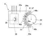
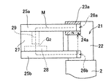
シャフト2の端部には、スロットル弁1の開度を検出する回転角検出装置6が設けられている。図2は回転角検出装置6の構成を示す平面図、図3は図2の回転角検出装置を図2のX方向から見た場合の側面図である。回転角検出装置6では、スロットル弁1が取り付けられたシャフト2が被検出体となり、その回転角度が検出される。シャフト2は磁性体にて形成され、その端部には作動部21として小径部22が設けられている。
【0031】
小径部22には、瓦状のマグネット23a,23bが軸方向に間隔をあけて接着等により固定されている。マグネット23a,23bは半円筒形に形成されており、断面が円弧形状となった外周面24a,24bを有している。外周面24a,24bは中心角が180°分の円周を有している。マグネット23a,23bはラジアル着磁が施されており、表面側の磁極を互いに異にしている。マグネット23aはN極が、マグネット23bはS極がそれぞれ表面に配されている。なお、マグネット23a,23bは、外周面24a,24bが円弧状であれば良く、内周面は必ずしも円弧状でなくとも良い。
【0032】
小径部22には、ステータプレート25a,25b(第1及び第2のステータ部材、以下、プレート25a,25bと略記する)が隣接配置されている。プレート25a,25bは磁性体にて形成され、マグネット23a,23bに合わせて軸方向に間隔をあけて配置されている。プレート25a,25bの端部には、マグネット23a,23bの外周面24a,24bに対向する対向面26a,26bが設けられている。対向面26a,26bはマグネット23a,23bの外側に配置され、円弧部48aと、円弧部48aの両端に形成された拡開部48bとから構成される。円弧部48aは、マグネット23a,23bの外周面24a,24bと略一定間隔のエアギャップG1をあけて対向する。これに対し、拡開部48bは円弧部48aから接線状に延伸し、外周面24a,24bとの間の間隙は末端部ほど増大するようになっている。
【0033】
プレート25a,25bの間には、合成樹脂等の非磁性体にて形成された支持ブロック(支持部剤)27が取り付けられている。支持ブロック27内には、プレート25b側にホールIC(磁気検出素子)28が取り付けられている。ホールIC28は、ホール素子と信号増幅回路とを一体化したICであり、リニア出力ホールICが使用されている。一方、支持ブロック27のプレート25a側には、磁性体にて形成されたポールピース(ポール部材)29が取り付けられている。ポールピース29は円柱形に形成されており、その先端はプレート25aから軸方向に沿って延び、ホールIC28の端面と対向している。
【0034】
ホールIC28は、マグネット23aからプレート25a,25bを介してマグネット23bに至る磁路M中に配置される。ここでは、図2に示すように、マグネット23a→対向面26a→プレート25a→ポールピース29→ホールIC28→プレート25b→対向面26b→マグネット23bなる経路の磁路Mが形成される。マグネット23aからプレート25aに至った磁束は、図3に示すようにポールピース29に収束されてホールIC28を通過する。このため、マグネット23a,23bの磁束を効率良くホールIC28に導くことができ、磁束変化の検出精度向上が図られる。また、ポールピース29の先端とホールIC28との間の間隙G2を調整することにより、ホールIC28に流入する磁束量を調節でき、ホールIC28の感度調整も可能である。
【0035】
モータ3は、図1に示すように、ステータ31の内側にロータ32を回転自在に配置したいわゆるインナーロータ型のブラシレスモータである。ステータ31は、駆動コイル33と、コイル33が巻装されたステータコア34とから構成され、基板30に固定されている。ステータコア34は、金属板を積層して形成されており、内周側に突設された突極に駆動コイル33が巻回されて巻線が形成されている。基板30には、ロータ32の回転位置を検出するホールIC(図示せず)が設けられている。このホールICからはロータ32に回転に伴って、ロータ位置検出信号が出力される。
【0036】
ロータ32は、ロータシャフト35と、ロータシャフト35に固定されたロータコア36及びロータコア36の外周に固定されたロータマグネット37とから構成される。ロータマグネット37は円筒状に形成され、N,Sの極が等間隔に配置されている。ロータシャフト35はベアリング38a,38bにて回転自在に支持されており、ベアリング38aはカバー5に、ベアリング38bはハウジング4に取り付けられたブラケット39にそれぞれ取り付けられている。
【0037】
ロータコア36には、円柱状のマグネット取付部36aと、ギヤ14が形成されている。ギヤ14は、アイドルギヤ18のギヤ13と噛合している。アイドルギヤ18は、ブラケット39に固定されたギアシャフト19に回転自在に支持されている。アイドルギヤ18にはギヤ13と一体にギヤ12が形成されており、ギヤ12はシャフト2に固定されたギア11と噛合している。これにより、モータ3におけるロータ32の回転が減速されてシャフト2に伝達される。
【0038】
次に、このような電子制御スロットル弁における回転角検出装置6の作用について説明する。当該電子制御スロットル弁では、スロットル弁1が全閉状態のとき回転角検出装置6において図3の状態(θ=0°)となるように設定されている。シャフト2は、スロットル弁1の全閉・全開に合わせて、θ=0°〜90°の間で動作し、シャフト2の回転に伴って磁路Mの磁束密度が変化する。この磁束密度変化によるホールIC28の出力電圧の変化に基づき、シャフト2の回転角度、すなわちスロットル弁1の開度が検出される。回転角検出装置6は、シャフト2の回転角が180°センシング可能な仕様となっており、そのセンシング領域の一部を用いてスロットル弁1の開度検出を行う。
【0039】
回転角検出装置6では、シャフト2の回転に伴い、対向面26a,26bとマグネット23a,23bの外周面24a,24bとの対向面積Sが変化する。図4は、図3の状態からシャフト2が角度θ1だけ回転した状態を示す説明図である。図4に示すように、シャフト2が回転すると、外周面24aの下方は対向面26aから離れ、対向面26aには外周面24aと対向しない部分が生じる。つまり、シャフト2の回転により対向面積Sが減少する。なお、マグネット23b側においても同様に、対向面26bとマグネット23bの外周面24bとの対向面積が減少する。
【0040】
磁路Mにおいては、マグネット23aから対向面26aを介してプレート25aに磁束が流入する。従って、対向面26aと外周面24aの対向面積Sが減少すると、その分、マグネット23aからプレート25aに流入する磁束も減少する。この際、磁束減少の割合は対向面積Sの減少に比例する。すなわち、シャフト2の回転に伴い、磁路M中に位置するホールIC28を通過する磁束の密度も回転角に比例して直線的に変化する。そして、この磁束変化に基づき、ホールIC28からはシャフト2の回転角度に比例した直線的な電圧信号が出力される。
【0041】
なお、マグネット23a,23bでは、シャフト21側の磁極からシャフト21を介して対向面26a,26bとの間で磁路が形成され、ホールIC28からの信号がθ=0°近傍にてやや曲線的になる傾向がある。そこで、当該回転角検出装置6では、対向面26a,26bの端部に拡開部48bを設け、対向面26a,26bとシャフト21との間の距離(エアギャップ)をより大きくしている。このため、シャフト21を介した前述の磁路が形成されにくくなっており、出力信号の曲線部分を減少させ、より直線領域の広い信号出力をホールIC28から得ることができる。
【0042】
このようにして得られたホールIC28からの出力信号は制御装置(CPU)に送られる。制御装置には、ホールIC28の出力変化がシャフト2の回転角度と関係付けてテーブル等の形で格納されている。制御装置は、ホールIC28の出力変化に基づき、テーブル等を参照しつつシャフト2の回転角度、すなわちスロットル弁1の開度を算出する。
【0043】
このように回転角検出装置6では、半円筒形状のマグネット23a,23bと半円状の対向面26a,26bを備えたプレート25a,25bによって磁路Mを形成しているので、従来、図12のようにシャフト2の全周に亘って形成されていた磁路がシャフト2の半周のみに削減される。このため、マグネット23a,23bと対向面26a,26bとの間に働く磁気的吸引力も半周分となり、シャフト2のフリクショントルクを低減させることができる。また、半円筒形状のマグネット23a,23bを使用してシャフト2の片側領域のみで回転角検出装置6を構成できるため、マグネット使用量を低減できると共に、装置が全周に亘って配される従来の回転角検出装置に比してレイアウト性も向上する。
【0044】
さらに、プレート25a,25bは磁性体の薄板にて構成できるため、これらと対向するマグネット23a,23bもその軸方向長を短くすることができる。従って、この点においてもマグネットの使用量を削減することができ、部品コストや重量を低減させることが可能となる。
【0045】
なお、回転角検出装置6では、マグネット23bを省くことも可能である。図5は、回転角検出装置6においてマグネット23bを省いた変形例の構成を示す平面図である。ここでは、磁路Mはマグネット23aの表裏にあるN極とS極の間で形成される。すなわち、マグネット23a(表面N極)→対向面26a→プレート25a→ポールピース29→ホールIC28→プレート25b→対向面26b→小径部22→マグネット23a(裏面S極)なる経路の磁路Mが形成される。このように図5の装置ではマグネット23bが省かれ、マグネット使用量の更なる削減が可能となる。但し、磁束量確保の点では図2の構成の方が有利である。
【0046】
(実施の形態2)
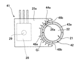
図6は、本発明の実施の形態2である回転角検出装置41の構成を示す平面図、図7は図6の回転角検出装置を図3と同様に見た側面図である。なお、以下の実施の形態では、回転角検出装置以外の部分は実施の形態1の電子制御スロットル弁と同様であるためその説明は省略する。また、実施の形態1と同様の部分、部材には同一の符号を使用する。
【0047】
回転角検出装置41では、円筒形のマグネット42が作動部21の小径部22に取り付けられている。マグネット42は、軸方向に2層の磁極層43a,43b(第1及び第2の磁極層)を有している。各磁極層43a,43bは、互いに隣接する磁極の極性を異にする2極の磁極をそれぞれ有している。つまり、各磁極層43a,43bはそれぞれ円周方向に2極に着磁されると共に、磁極層43a,43b同士の間では、隣接する磁極層の極性が異なるように各磁極が配置されている。
【0048】
マグネット42の外側にはプレート25a,25bが配設されている。プレート25aの対向面26aには、磁極層43aの外周面44aが略一定間隔のエアギャップG1をあけて対向する。一方、プレート25bの対向面26bには、磁極層43bの外周面44bが略一定間隔のエアギャップG1をあけて対向する。磁極層43a,43b間には、磁極層43a→対向面26a→プレート25a→ポールピース29→ホールIC28→プレート25b→対向面26b→磁極層43bなる経路の磁路Mが形成される。
【0049】
回転角検出装置41では、シャフト2の回転に伴い、対向面26a,26bと対向するマグネット42の極性が変化する。図8は、図7の状態からシャフト2が角度θ1だけ回転した状態を示す説明図である。図8に示すように、シャフト2が回転すると、磁極層43aのN極下方は対向面26aから離れ、対向面26a上方に磁極層43aのS極が対向する。すると、磁極層43aのN極からプレート25aを介してプレート25b側に向かっていた磁束の一部が、プレート25a中にて磁極層43a自身のS極に向かう。つまり、対向面26aとの対向面積が相等しい異極性の磁極からの磁束はプレート25a内にて閉ループを形成し、平衡成分となる。そして、この平衡成分以外の不平衡成分が磁路Mを流通し、その分だけ磁路M中を流れる磁束量が減少する。
【0050】
回転角検出装置41においてもホールIC28を通過する磁束の密度は、シャフト2の回転角に比例して直線的に変化する。ホールIC28からはシャフト2の回転角度に比例した直線的な電圧信号が出力され、この信号に基づきシャフト2の回転角が算出される。この際、回転角検出装置41では不平衡成分を積極的に形成しているため、回転角に応じた磁路Mの磁束量変化は、先の回転角検出装置6よりも大きくなる。従って、回転角に対する感度をより高めることができ、角度検出精度が向上する。なお、回転角検出装置41は、円筒形状のマグネット42を使用しているため、シャフト2の回転角度を360°検出可能である。
【0051】
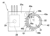
回転角検出装置41では、マグネット42の各磁極層43a,43bを1極構成とすることもできる。図9は、回転角検出装置41において各磁極層43a,43bを1極構成とした変形例の構成を示す平面図である。ここでは、マグネット42は半円筒形状に形成され、磁極層43aは外周面44aにN極のみが,磁極層43bは外周面44bにS極のみが配されている。つまり、図2の回転角検出装置6において、マグネット23a,23bを一体化した構成となっており、図9の回転角検出装置45は実施の形態1,2の複合形態となっている。
【0052】
(実施の形態3)
図10は、本発明の実施の形態3である回転角検出装置46の構成を示す側面図である。前述の実施の形態では、作動部21においてシャフト2に直接マグネット23a等を取り付けた構成を示したが、作動部21に磁性体からなるコア47を取り付け、その外側にマグネットを取り付ける形としても良い。この場合、コア47によって磁路を形成することができるため、シャフト2が磁性体にて形成されていない場合にも当該回転角検出装置を使用することができる。なお、図10では、図2,3の回転角検出装置6においてシャフト2にコア47を取り付けた構成を示しているが、回転角検出装置41,45においても同様の構成を採ることも可能である。
【0053】
本発明は前記実施の形態に限定されるものではなく、その要旨を逸脱しない範囲で種々変更可能であることは言うまでもない。
例えば、前述の実施の形態1では、外周面中心角を180°とした半円筒形状のマグネットを用いた構成を示したが、中心角は180°には限定されず、検出角度範囲に応じて適宜変更可能である。また、対向面の角度もそれに合わせて適宜変更可能である。
【0054】
加えて、前述の実施の形態では本発明による回転角検出装置を電子制御スロットル弁の開度検出に用いた例を示したが、その適用対象はこれには限定されず、モータ回転軸等、回転体の回転角度検出に広く適応可能である。
【0055】
【発明の効果】
本発明の回転角検出装置によれば、被検出体に設けられた磁性体からなる作動部に第1及び第2のマグネットを取り付けると共に、各マグネットと軸方向に間隔をあけて対向する対向面を備えた磁性体よりなる第1及び第2のステータ部材を設け、第1のマグネットから第1及び第2のステータ部材を介して第2のマグネットに至る磁路中に磁気検出素子を配置したので、作動部周囲の磁路を削減できマグネットと対向面との間に働く磁気的吸引力を低減できる。従って、被検出体の回転抵抗力を低減させることができる。また、被検出体の片側領域のみで回転角検出装置を構成することができ、マグネット量の低減やレイアウト性の向上を図ることが可能となる。
【図面の簡単な説明】
【図1】本発明の実施の形態1である回転角検出装置を使用した電子制御スロットル弁の構成を示す断面図である。
【図2】本発明の実施の形態1である回転角検出装置の構成を示す平面図である。
【図3】図2の回転角検出装置を図2のX方向から見た場合の側面図である。
【図4】図3の状態からシャフトが角度θ1だけ回転した状態を示す説明図である。
【図5】図2の回転角検出装置において一方のマグネットを省いた変形例の構成を示す平面図である。
【図6】本発明の実施の形態2である回転角検出装置の構成を示す平面図である。
【図7】図6の回転角検出装置を図3と同様に見た側面図である。
【図8】図7の状態からシャフトが角度θ1だけ回転した状態を示す説明図である。
【図9】図6の回転角検出装置において各磁極層を1極構成とした変形例の構成を示す平面図である。
【図10】本発明の実施の形態3である回転角検出装置の構成を示す側面図である。
【図11】従来の回転角検出装置の構成を示す説明図である。
【符号の説明】
1 スロットル弁
2 シャフト
3 ブラシレスモータ
4 ハウジング
5 カバー
6 回転角検出装置
11〜14 ギア
15 減速機構
16a,16b ベアリング
17 ねじりコイルばね
18 アイドルギヤ
19 ギアシャフト
21 作動部
22 小径部
23a,23b マグネット
24a,24b 外周面
25a,25a ステータプレート(ステータ部材)
26a,26b 対向面
27 支持ブロック(支持部材)
28 ホールIC(磁気検出素子)
29 ポールピース(ポール部材)
30 基板
31 ステータ
32 ロータ
33 駆動コイル
34 ステータコア
35 ロータシャフト
36 ロータコア
36a マグネット取付部
37 ロータマグネット
38a,38b ベアリング
39 ブラケット
41 回転角検出装置
42 マグネット
43a,43b 磁極層
44a,44b 外周面
45 回転角検出装置
46 回転角検出装置
47 コア
48a 円弧部
48b 拡開部
51 シャフト
52 ロータコア
53 リングマグネット
54 ステータコア
54a コアピース
55 間隙
56 ホールIC
G1 エアギャップ
G2 間隙
M 磁路
S 対向面積[0001]
TECHNICAL FIELD OF THE INVENTION
The present invention relates to a rotation angle detection device that detects a rotation angle of an object to be detected, and more particularly to a technique that is effective when applied to a detection device for a throttle valve opening of an engine.
[0002]
[Prior art]
2. Description of the Related Art Conventionally, as a non-contact type rotation angle detecting device, there is known a device in which a magnet is attached to an object to be detected and a change in magnetic flux is detected to detect the rotation angle of the object as disclosed in Japanese Patent No. 2,842,482. Have been.
[0003]
In the rotation angle detection device of FIG. 12, a
[0004]
As shown in FIG. 12, the
[0005]
On the other hand, in recent years, so-called electronically controlled throttle devices that drive a throttle valve of an engine by a motor have been widely used with the digitization of automobile parts. Here, the throttle valve is controlled by an electric signal instead of the mechanical operation by the conventional accelerator wire. The accelerator depression amount is electrically detected by a potentiometer or the like, and a motor is driven according to the value to open and close the throttle valve.
[0006]
In such an electronic control throttle device, the opening of the throttle valve is detected by a rotation angle detection device as shown in FIG. 12, but in addition to this, an outer rotor type detection device in which a magnet is arranged outside the stator core is also used. Many are used. For example, JP-A-2001-208510 and JP-A-2001-289610 disclose such an outer rotor type device. Here, when the shaft to which the throttle valve is fixed is driven by a motor, the rotation angle of the shaft, that is, the opening of the throttle valve is detected by the output signal of the Hall IC. Then, the operation of the motor is controlled based on the detected valve opening, and the valve opening is set according to the accelerator pedal depression amount, the engine load, and the like.
[0007]
[Patent Document 1] Japanese Patent No. 2842282
[Patent Document 2] JP-A-8-35809
[Patent Document 3] JP-A-2001-4315
[Patent Document 4] JP-A-2001-59702
[Patent Document 5] JP-A-2001-188003
[Patent Document 6] JP-A-2001-208510
[Patent Document 7] JP-A-2001-289609
[Patent Document 8] JP-A-2001-289610
[Patent Document 9] JP-A-2001-303979
[Patent Document 10] JP-A-2001-317909
[Patent Document 11] Japanese Patent Application No. 2002-21201
[Patent Document 12] Japanese Patent Application No. 2002-257723
[Patent Document 13] Japanese Patent Application No. 2002-258901
[0008]
[Problems to be solved by the invention]
However, in the rotation angle detecting device as shown in FIG. 12, as shown in FIG. 12, since the entire circumference of the
[0009]
Further, in the rotation angle detection device of FIG. 12, since the
[0010]
SUMMARY OF THE INVENTION An object of the present invention is to provide a low-cost rotation angle detection device that has a small friction torque and is excellent in layout.
[0011]
[Means for Solving the Problems]
The rotation angle detection device according to the present invention includes an operation unit formed of a magnetic material provided on a detection target whose rotation angle is required to be detected, a first magnet attached to the operation unit, and the first magnet. A second magnet having a polarity different from that of the first magnet, attached to the operating portion with an interval in the axial direction, and a second magnet arranged outside the first magnet and having a gap with the first magnet. A first stator member formed of a magnetic material and having an opposing surface that is spaced apart from the first magnet; and a first stator member that is axially spaced apart from the first stator member and that is spaced apart from the second magnet. A second stator member formed of a magnetic material and having a facing surface that is spaced apart from the first magnet, and extending from the first magnet to the second magnet via the first and second stator members; In the magnetic path And having a arranged magnetic sensor.
[0012]
According to the present invention, since the magnetic path is formed by the first and second magnets and the stator member having the opposing surface facing the magnet, the magnetic path around the operating portion can be reduced, and the magnetic path facing the magnet can be reduced. It is possible to reduce the magnetic attraction force acting on the surface. Therefore, the rotational resistance of the detected object can be reduced. In addition, since the rotation angle detection device can be configured with only one side region of the detection target, the amount of magnets can be reduced and the layout can be improved.
[0013]
In the rotation angle detecting device, the first and second magnets each have an outer peripheral surface having an arc-shaped cross section, and the opposed surfaces of the first and second stator members are respectively substantially equal to the respective outer peripheral surfaces. They may be opposed at regular intervals.
[0014]
Further, in the rotation angle detecting device, the first and second magnets each have an outer peripheral surface having an arc-shaped cross section, and the opposed surfaces of the first and second stator members respectively have the respective shapes. An arc portion facing the outer peripheral surface at a substantially constant interval may be provided, and an expanding portion formed at an end of the arc portion and increasing the distance between the outer peripheral surfaces toward the end may be provided. As a result, it is difficult to form a magnetic path from the magnet to the opposing surface via the operating portion, the output signal curve portion is reduced, and it is possible to obtain a signal output with a wider linear region from the magnetic detection element.
[0015]
Another rotation angle detection device of the present invention includes an operation unit made of a magnetic material provided on a detection target whose rotation angle is required to be detected, a magnet attached to the operation unit, and a magnet disposed outside the magnet. A first stator member formed of a magnetic material and having a facing surface facing the magnet at an interval; and a first stator member axially spaced from the first stator member; A second stator member formed of a magnetic material, comprising a facing surface facing the portion at an interval, and the magnet from the magnet via the first and second stator members and the operating portion. And a magnetic sensing element arranged in a magnetic path leading to
[0016]
According to the present invention, since the magnetic path is formed by the magnet and the stator member having the opposing surface facing the magnet and the operating portion, the magnetic path around the operating portion can be reduced, and the distance between the magnet and the opposing surface can be reduced. The magnetic attraction force acting on the surface can be reduced. Therefore, the rotational resistance of the detected object can be reduced. In addition, since the rotation angle detection device can be configured with only one side region of the detection target, layout characteristics are also improved. Further, since the magnetic path is formed by one magnet, the amount of magnet used can be further reduced.
[0017]
In the rotation angle detection device, an outer peripheral surface having an arc-shaped cross section is formed on the magnet, and the opposed surface of the first stator member is opposed to the outer peripheral surface at a substantially constant interval, and The opposed surface of the second stator member may be opposed to the operating portion at a substantially constant interval.
[0018]
In the rotation angle detecting device, the magnet may have an outer peripheral surface having an arc-shaped cross section, and may be opposed to the opposed surface of the first stator member at a substantially constant interval from the outer peripheral surface. An arcuate portion and an expanding portion formed at an end of the arcuate portion and increasing the distance between the outer peripheral surfaces toward the end may be provided. As a result, it is difficult to form a magnetic path from the magnet to the opposing surface via the operating portion, the output signal curve portion is reduced, and it is possible to obtain a signal output with a wider linear region from the magnetic detection element.
[0019]
Further, in the rotation angle detecting device, the magnet may be formed in a semi-cylindrical shape in which a center angle of the outer peripheral surface is formed to be approximately 180 °. As described above, by using a magnet having an outer peripheral surface with a partial arc cross section such as a semi-cylindrical shape, the amount of magnet used can be reduced by half with respect to a ring magnet having a circular cross section.
[0020]
On the other hand, another rotation angle detecting device according to the present invention includes an operating portion made of a magnetic material provided on a detection target whose rotation angle is required to be detected, And a magnet on which a second pole layer is formed, and a facing member disposed outside the first pole layer and facing the first pole layer at an interval. A first stator member, and a magnetic body comprising an opposing surface disposed at an axial distance from the first stator member and opposed to the second magnetic pole layer at an interval. A second stator member formed; and a magnetic sensing element disposed in a magnetic path from the first pole layer to the second pole layer via the first and second stator members. It is characterized by the following.
[0021]
According to the present invention, since the magnetic path is formed by the first and second magnetic pole layers and the stator member having the opposing surface facing each magnetic pole layer, the magnetic path around the operating portion can be reduced. Magnetic attraction acting between the magnet and the facing surface can be reduced. Therefore, the rotational resistance of the detected object can be reduced. Further, the rotation angle detecting device can be constituted only by one side region of the object to be detected, and since a plurality of magnetic pole layers are provided for one magnet, the dimension in the axial direction can be shortened and the layout property can be improved.
[0022]
In the rotation angle detecting device, an outer peripheral surface having a circular cross section is formed on the magnet, and the opposed surfaces of the first and second stator members are respectively opposed to the outer peripheral surfaces at substantially constant intervals. May be.
[0023]
In the rotation angle detection device, the magnet may have an outer peripheral surface having an arc-shaped cross section, and the opposing surfaces of the first and second stator members may have a substantially constant distance from the outer peripheral surface. An arcuate portion opposing at an interval and an expanding portion formed at an end of the arcuate portion and increasing the distance from the outer peripheral surface toward the end may be provided. As a result, it is difficult to form a magnetic path from the magnet to the opposing surface via the operating portion, the output signal curve portion is reduced, and it is possible to obtain a signal output with a wider linear region from the magnetic detection element.
[0024]
Further, in the rotation angle detecting device, the first and second magnetic pole layers may have one or two magnetic poles having different polarities of magnetic poles adjacent to each other.
[0025]
In addition, in the rotation angle detection device, the magnetic detection element may be disposed between the first and second stator members, and is formed of a non-magnetic material between the first and second stator members. A support member may be provided.
[0026]
Further, in the rotation angle detecting device, a pole member formed of a magnetic material and extending in at least one of the first and second stator members along an axial direction and having a front end portion facing the magnetic detection element. May be provided. Thereby, the magnetic flux of the magnet can be efficiently guided to the magnetic detection element, and the detection accuracy of the change in the magnetic flux can be improved. Further, by adjusting the gap between the tip of the pole member and the magnetic sensing element, the amount of magnetic flux flowing into the magnetic sensing element can be adjusted, and the sensitivity of the magnetic sensing element can be adjusted.
[0027]
On the other hand, in the rotation angle detection device, a rotation shaft to which an engine throttle valve is fixed may be used as the detection target.
[0028]
BEST MODE FOR CARRYING OUT THE INVENTION
(Embodiment 1)
Hereinafter, embodiments of the present invention will be described in detail with reference to the drawings. FIG. 1 is a sectional view showing a configuration of an electronically controlled throttle valve using a rotation angle detecting device according to
[0029]
The
[0030]
At an end of the
[0031]
Roof-shaped
[0032]
[0033]
A support block (support member) 27 made of a non-magnetic material such as a synthetic resin is attached between the
[0034]
The
[0035]
As shown in FIG. 1, the
[0036]
The
[0037]
On the
[0038]
Next, the operation of the rotation
[0039]
In the rotation
[0040]
In the magnetic path M, magnetic flux flows from the
[0041]
In the
[0042]
The output signal from the
[0043]
As described above, in the rotation
[0044]
Further, since the
[0045]
In the rotation
[0046]
(Embodiment 2)
FIG. 6 is a plan view showing a configuration of a rotation
[0047]
In the rotation
[0048]
[0049]
In the rotation
[0050]
Also in the rotation
[0051]
In the rotation
[0052]
(Embodiment 3)
FIG. 10 is a side view showing a configuration of a rotation angle detection device 46 according to the third embodiment of the present invention. In the above-described embodiment, the configuration is shown in which the
[0053]
The present invention is not limited to the above embodiment, and it goes without saying that various modifications can be made without departing from the scope of the invention.
For example, in the first embodiment described above, a configuration using a semi-cylindrical magnet having a center angle of the outer peripheral surface of 180 ° has been described. However, the center angle is not limited to 180 °, and may be determined according to the detection angle range. It can be changed as appropriate. Also, the angle of the facing surface can be appropriately changed according to the angle.
[0054]
In addition, in the above-described embodiment, an example in which the rotation angle detection device according to the present invention is used for detecting the opening degree of the electronically controlled throttle valve has been described. It is widely applicable to rotation angle detection of a rotating body.
[0055]
【The invention's effect】
According to the rotation angle detecting device of the present invention, the first and second magnets are attached to the operating portion made of the magnetic material provided on the detected object, and the opposing surface that faces each magnet at an interval in the axial direction. First and second stator members made of a magnetic material provided with a magnetic member are disposed in a magnetic path from the first magnet to the second magnet via the first and second stator members. Therefore, the magnetic path around the operating portion can be reduced, and the magnetic attraction acting between the magnet and the facing surface can be reduced. Therefore, the rotational resistance of the detected object can be reduced. In addition, the rotation angle detection device can be configured with only one side region of the detection target, and it is possible to reduce the amount of magnets and improve the layout.
[Brief description of the drawings]
FIG. 1 is a sectional view showing a configuration of an electronically controlled throttle valve using a rotation angle detection device according to a first embodiment of the present invention.
FIG. 2 is a plan view showing a configuration of a rotation angle detection device according to the first embodiment of the present invention.
FIG. 3 is a side view of the rotation angle detection device of FIG. 2 when viewed from the X direction of FIG. 2;
FIG. 4 is an explanatory view showing a state in which the shaft has been rotated by an angle θ1 from the state in FIG. 3;
FIG. 5 is a plan view showing a configuration of a modification in which one magnet is omitted in the rotation angle detecting device of FIG. 2;
FIG. 6 is a plan view illustrating a configuration of a rotation angle detection device according to a second embodiment of the present invention.
FIG. 7 is a side view of the rotation angle detection device of FIG. 6 viewed in the same manner as FIG. 3;
FIG. 8 shows a state in which the shaft is shifted from the state shown in FIG. 1 It is an explanatory view showing the state rotated only.
FIG. 9 is a plan view showing a configuration of a modification in which each magnetic pole layer has a single pole configuration in the rotation angle detection device of FIG. 6;
FIG. 10 is a side view illustrating a configuration of a rotation angle detection device according to a third embodiment of the present invention.
FIG. 11 is an explanatory diagram showing a configuration of a conventional rotation angle detection device.
[Explanation of symbols]
1 Throttle valve
2 shaft
3 brushless motor
4 Housing
5 Cover
6 Rotation angle detector
11-14 gears
15 Reduction mechanism
16a, 16b bearing
17 Torsion coil spring
18 Idle gear
19 Gear shaft
21 Working part
22 Small diameter part
23a, 23b magnet
24a, 24b outer peripheral surface
25a, 25a Stator plate (stator member)
26a, 26b Opposing surface
27 Support block (support member)
28 Hall IC (magnetic detection element)
29 Pole piece (pole member)
30 substrates
31 Stator
32 rotor
33 drive coil
34 Stator core
35 Rotor shaft
36 rotor core
36a Magnet mounting part
37 Rotor magnet
38a, 38b bearing
39 bracket
41 Rotation angle detector
42 magnet
43a, 43b magnetic pole layer
44a, 44b Outer peripheral surface
45 Rotation angle detector
46 Rotation angle detector
47 core
48a Arc section
48b Expanding part
51 shaft
52 rotor core
53 ring magnet
54 Stator core
54a core piece
55 gap
56 Hall IC
G 1 Air gap
G 2 gap
M magnetic path
S Opposing area
Claims (15)
前記作動部に取り付けられた第1のマグネットと、
前記第1のマグネットと軸方向に間隔をあけて前記作動部に取り付けられ、前記第1のマグネットとは異なる極性を有する第2のマグネットと、
前記第1のマグネットの外側に配置され、前記第1のマグネットと間隔をあけて対向する対向面を備えてなる、磁性体にて形成された第1のステータ部材と、
前記第1のステータ部材と軸方向に間隔をあけて配置され、前記第2のマグネットと間隔をあけて対向する対向面を備えてなる、磁性体にて形成された第2のステータ部材と、
前記第1のマグネットから前記第1及び第2のステータ部材を介して前記第2のマグネットに至る磁路中に配置された磁気検出素子とを有することを特徴とする回転角検出装置。An actuating unit made of a magnetic material provided on the object to be detected for which detection of the rotation angle is required,
A first magnet attached to the operating portion;
A second magnet that is attached to the operating unit at an axial distance from the first magnet and has a polarity different from that of the first magnet;
A first stator member formed of a magnetic material, having a facing surface disposed outside the first magnet and facing the first magnet at an interval;
A second stator member formed of a magnetic material, comprising: a second stator member that is disposed at an axial distance from the first stator member and has an opposing surface that faces the second magnet at an interval;
A rotation angle detection device, comprising: a magnetic detection element disposed in a magnetic path from the first magnet to the second magnet via the first and second stator members.
前記作動部に取り付けられたマグネットと、
前記マグネットの外側に配置され、前記マグネットと間隔をあけて対向する対向面を備えてなる、磁性体にて形成された第1のステータ部材と、
前記第1のステータ部材と軸方向に間隔をあけて配置され、前記作動部と間隔をあけて対向する対向面を備えてなる、磁性体にて形成された第2のステータ部材と、
前記マグネットから前記第1及び第2のステータ部材と前記作動部を介して前記マグネットに至る磁路中に配置された磁気検出素子とを有することを特徴とする回転角検出装置。An actuating unit made of a magnetic material provided on the object to be detected for which detection of the rotation angle is required,
A magnet attached to the operating portion,
A first stator member formed of a magnetic material, comprising a facing surface disposed outside the magnet and facing the magnet at an interval;
A second stator member formed of a magnetic material, comprising a facing surface that is disposed at an axial distance from the first stator member and faces the operating portion at a distance;
A rotation angle detection device comprising: a first and a second stator member from the magnet; and a magnetic detection element disposed in a magnetic path from the magnet to the magnet via the operating portion.
前記作動部に取り付けられ、軸方向に隣接して第1及び第2の磁極層が形成されたマグネットと、
前記第1の磁極層の外側に配置され、前記第1の磁極層と間隔をあけて対向する対向面を備えてなる、磁性体にて形成された第1のステータ部材と、
前記第1のステータ部材と軸方向に間隔をあけて配置され、前記第2の磁極層と間隔をあけて対向する対向面を備えてなる、磁性体にて形成された第2のステータ部材と、
前記第1の磁極層から前記第1及び第2のステータ部材を介して前記第2の磁極層に至る磁路中に配置された磁気検出素子とを有することを特徴とする回転角検出装置。An actuating unit made of a magnetic material provided on the object to be detected for which detection of the rotation angle is required,
A magnet attached to the operating portion and having first and second pole layers formed adjacent to each other in the axial direction;
A first stator member formed of a magnetic material, comprising a facing surface disposed outside the first pole layer and facing the first pole layer at an interval;
A second stator member formed of a magnetic material, comprising a facing surface that is arranged at an axial distance from the first stator member and faces the second magnetic pole layer at an interval; ,
A rotation angle detection device, comprising: a magnetic detection element disposed in a magnetic path from the first pole layer to the second pole layer via the first and second stator members.
Priority Applications (1)
| Application Number | Priority Date | Filing Date | Title |
|---|---|---|---|
| JP2003030407A JP2004239799A (en) | 2003-02-07 | 2003-02-07 | Rotation angle detecting device |
Applications Claiming Priority (1)
| Application Number | Priority Date | Filing Date | Title |
|---|---|---|---|
| JP2003030407A JP2004239799A (en) | 2003-02-07 | 2003-02-07 | Rotation angle detecting device |
Publications (1)
| Publication Number | Publication Date |
|---|---|
| JP2004239799A true JP2004239799A (en) | 2004-08-26 |
Family
ID=32957304
Family Applications (1)
| Application Number | Title | Priority Date | Filing Date |
|---|---|---|---|
| JP2003030407A Pending JP2004239799A (en) | 2003-02-07 | 2003-02-07 | Rotation angle detecting device |
Country Status (1)
| Country | Link |
|---|---|
| JP (1) | JP2004239799A (en) |
Cited By (4)
| Publication number | Priority date | Publication date | Assignee | Title |
|---|---|---|---|---|
| JP2006118875A (en) * | 2004-10-19 | 2006-05-11 | Koyo Electronics Ind Co Ltd | Torque sensor |
| JP2006133011A (en) * | 2004-11-04 | 2006-05-25 | Koyo Electronics Ind Co Ltd | Torque sensor |
| CN102809345A (en) * | 2011-06-03 | 2012-12-05 | 陈捷圻 | Torsion-angle turning-angle displacement sensing device |
| WO2017041325A1 (en) * | 2015-09-07 | 2017-03-16 | 中国科学院地质与地球物理研究所 | Magnetic field-based micro-vibration measuring device and measuring method thereof |
-
2003
- 2003-02-07 JP JP2003030407A patent/JP2004239799A/en active Pending
Cited By (6)
| Publication number | Priority date | Publication date | Assignee | Title |
|---|---|---|---|---|
| JP2006118875A (en) * | 2004-10-19 | 2006-05-11 | Koyo Electronics Ind Co Ltd | Torque sensor |
| JP2006133011A (en) * | 2004-11-04 | 2006-05-25 | Koyo Electronics Ind Co Ltd | Torque sensor |
| CN102809345A (en) * | 2011-06-03 | 2012-12-05 | 陈捷圻 | Torsion-angle turning-angle displacement sensing device |
| US9035666B2 (en) | 2011-06-03 | 2015-05-19 | Chieh Chi CHEN | Torsion angle and rotation angle measurement device |
| WO2017041325A1 (en) * | 2015-09-07 | 2017-03-16 | 中国科学院地质与地球物理研究所 | Magnetic field-based micro-vibration measuring device and measuring method thereof |
| US10697826B2 (en) | 2015-09-07 | 2020-06-30 | Institute Of Geology And Geophysics Chinese Academy Of Sciences (Iggcas) | Magnetic field based micro-vibration measurement device and measuring method thereof |
Similar Documents
| Publication | Publication Date | Title |
|---|---|---|
| JP4169536B2 (en) | Actuator | |
| US6771065B2 (en) | Line hall effect detector and method of sensing angular position particularly suited for electrical rotary actuator | |
| JP2005054654A (en) | Intake air control device for engine | |
| JP4204294B2 (en) | Rotation angle detector | |
| JP2005048671A (en) | Engine intake control device | |
| EP2208978A2 (en) | Compact magnetic torque sensing systems | |
| EP1679491A1 (en) | Rotation angle detection device | |
| JP2004239799A (en) | Rotation angle detecting device | |
| JP6914443B2 (en) | Motor and valve timing adjuster | |
| JP2004245703A (en) | Rotational angle detection device | |
| JP2001208510A (en) | Angle-of-rotation detector | |
| JPH07119619B2 (en) | Angle sensor | |
| JP4073758B2 (en) | Rotating electric machine for vehicles | |
| JP2004092590A (en) | Opening detecting device for throttle valve | |
| JP3814041B2 (en) | Stepping motor with rotor position detection mechanism | |
| JP5848160B2 (en) | Rotor and motor | |
| JP2004124718A (en) | Electronic control throttle device | |
| JP2006300704A (en) | Rotation angle detecting sensor | |
| JP4103040B2 (en) | Rotation position detector | |
| JP2019525701A (en) | Electrical equipment | |
| JP2000139067A (en) | Torque motor and throttle device therewith | |
| JP2004072827A (en) | Field control motor | |
| JPH11299209A (en) | Torque motor | |
| JP2005181209A (en) | Phase angle detector for rotor | |
| JP2002031505A (en) | Non-contact rotation angle sensor and its sensor core |