JP2004239723A - Electron beam irradiator - Google Patents
Electron beam irradiator Download PDFInfo
- Publication number
- JP2004239723A JP2004239723A JP2003028290A JP2003028290A JP2004239723A JP 2004239723 A JP2004239723 A JP 2004239723A JP 2003028290 A JP2003028290 A JP 2003028290A JP 2003028290 A JP2003028290 A JP 2003028290A JP 2004239723 A JP2004239723 A JP 2004239723A
- Authority
- JP
- Japan
- Prior art keywords
- irradiated
- catcher
- electron beam
- beam catcher
- suction
- Prior art date
- Legal status (The legal status is an assumption and is not a legal conclusion. Google has not performed a legal analysis and makes no representation as to the accuracy of the status listed.)
- Granted
Links
Images


Abstract
Description
【0001】
【発明の属する技術分野】
本発明は電子線照射装置に関する。
【0002】
【従来の技術】
【0003】
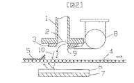
図2は従来例1を示す。電子線が窓箔2を透過するとき、そのエネルギーの一部が失われ、窓箔2は発熱する。過度の発熱に伴う窓箔2の損傷を防止するために、冷却風ダクト8から供給された冷却風10をノズル9によって窓箔2に吹き付けて冷却している。窓箔2は走査管1の内部が真空状態にあるから図に示すように凹み、ノズル9からの冷却風10は、矢印で示すように流れ、照射領域のメッシュコンベア4上に被照射シート5が存在しないとき、メッシュコンベア4を通り抜けてビームキャッチャ6に当って反転する。
【0004】
したがって、メッシュコンベア4に載置されて被照射シート5の先端部が照射領域に導入されるとき、ビームキャッチャ6で反転した冷却風10によって被照射シート5の先端部がめくれ上がる現象が発生する。一般に電子線照射装置にあっては、電子線によるオゾンの発生、エネルギー損失を抑えるために、窓箔2から被照射シート5に到達するまでの電子線通過雰囲気層の距離が短くなるように構成されているから、被照射シート5先端部のめくれ現象発生は電子線照射装置の円滑な運転を阻害する。
【0005】
以上の問題解決の為、図3の従来例2では、メッシュコンベア4の下方位置に複数のパイプ状ビームキャッチャ16及び鉛ターゲット17を分割配置する事により、冷却風10をビームキャッチャ16で反転し難くさせ、冷却風10によって被照射シート5の先端部がめくれ上がる現象を軽減させている。
【0006】
さらに、排気装置19をメッシュコンベア4の下部に設け、被照射シート5先端部の下面の雰囲気気体を排気ブロワ21で排気させることにより、シート先端部はメッシュコンベア4に密着し、めくれ防止機能を更に助長している。
【0007】
各ビームキャッチャ16は内部を冷却水が通流するステンレス製のパイプで構成されており、鉛ターゲット17は電子線が直接当らないように、ビームキャッチャの電子線が当る側とは反対側の周面部に取り付けられている。複数のビ−ムキャッチャ16は、それぞれ間隔、隙間を置いて並設されており、ビームキャッチャ間の隙間を通り抜ける電子線を吸収、捕捉できるように例えば2段に配置する。鉛ターゲット17は、捕捉した電子線から発生する放射線を吸収するためのものである。
【0008】
以上の様に、窓箔2の冷却風10により被照射物5がめくれ上がり窓箔2の損傷が起こることを、メッシュコンベア4の下部にパイプ状ビームキャッチャ16と排気装置19(吸引機構)を設け、照射領域に導入された被照射シート5の先端部の下面の雰囲気気体を強制的に排気(吸引)することにより、被照射シート5先端部をメッシュコンベア4に密着し、めくれ上がりを防止することができる機構は、従来から提案されている。(たとえば、特許文献1参照。)
【0009】
【特許文献1】
実開平7−18300号公報(請求項1、図1)
【0010】
【発明が解決しようとする課題】しかし、上記従来例2においては、吸引流の為にビームキャッチャ間に隙間を設ける必要があり、この隙間によりビームの全てがキャッチ出来ずに吸引機構にビームが当たり、吸引機構を加熱する。この熱放散の為に吸引ダクト周辺の空間を広くとる必要があり、装置が大型化する。また、ビームキャッチャを特殊な機構とする必要がある。
【課題を解決するための手段】本発明は、冷却風により冷却される窓箔と、気流を通す被照射物搬送用のコンベアを有する搬送装置と、板状ビームキャッチャと、板状ビームキャッチャ側面又は側面やや下方より被照射物を吸引するための吸引機構とを備える。
【0011】
さらに、吸引機構の小型化・高効率化を実現する為、吸引空間を制限する目的にビームキャッチャ表面に突起を設ける。これにより吸引容量の小さな吸引ブロワでも被照射物を吸引することができる。また、突起の代りにビームキャッチャ表面に窪みを設けても同一の効果が生まれる。
【0012】
【発明の実施の形態】
本発明の実施例を図1によって説明する。なお図2又は図3と同じ符号を付した部分は同一または対応する部分を示す。ビームキャッチャ6及び鉛ターゲット7は板状のものである。ビームキャッチャ6には発熱を低減する為、冷却水孔23を設けてある。板状ビームキャッチャの側面又は側面やや下方には吸引ダクト20を設ける。
【0013】
ビームキャッチャ6で反転した冷却風10によって、被照射物5をめくれ上げる力が発生するが、吸引機構19からの吸引流22により被照射物5を搬送装置4に引き付ける事が出来る為、めくれ上げられることが無くなる。
【0014】
冷却風10により被照射物5がめくれ上げられるのは、コンベア4に載置されて被照射シート5の先端部が照射領域に導入されるときであり、走査管1の真下ではめくれ上げられる力は弱い。つまり、走査管1の中央に向かって搬送される部分を下方に向かう力で固定すれば、被照射物はめくれ上げられなくなる。当該下方に向かう力を吸引機構19にて実現している。
【0015】
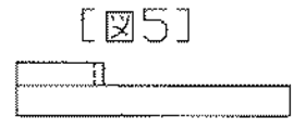
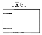
上記の吸引流22を効率的に発生させる為、図4及び図5の様にビームキャッチャ上に突起により壁を設ける。これにより、吸引対象範囲が制限される為吸引ブロワの容量を小さくできる。同様に図6及び図7の様にビームキャッチャの一部に窪みを設ける事でも同様の効果が生まれる。
【0016】
気流を通す搬送装置4は被照射物5を乗せる部分にメッシュ構造のものを用いるか複数の孔を開けることで実現する。この事から吸引流22により被照射物5を搬送装置4に固定する事が可能となる。
【0017】
板状ビームキャッチャは1枚の板で実現しても良いが、市販角型パイプを一列に並べて配置することでも実現できる。当該方式により冷却水孔23の特殊加工が不用となり、コストダウンに寄与する。
【発明の効果】
以上説明したように本発明によれば、板状ビームキャッチャを用いる事ができるため、構造の簡単な被照射シートのめくれ防止機構を備えた電子線照射装置が実現できる。なお、本発明によれば、既に納入済の製品についても、吸引機構を容易に追加する事が可能である。
【図面の簡単な説明】
【図1】本発明の実施例を示す断面図である。
【図2】従来例1の断面図である。
【図3】従来例2の断面図である。
【図4】本発明の突起方式のビームキャッチャ上面図である。
【図5】本発明の突起方式のビームキャッチャ側面図である。
【図6】本発明の窪み方式のビームキャッチャ上面図である。
【図7】本発明の窪み方式のビームキャッチャ側面図である。
【符号の説明】
1 走査管
2 窓箔
4 コンベア(メッシュコンベア)
5 被照射物(被照射シート)
6 ビームキャッチャ
7 鉛ターゲット
9 冷却風ノズル
10 冷却風
19 吸引機構(排気装置)
20 吸引ダクト(排気ダクト)
21 吸引ブロワ(排気ブロワ)[0001]
BACKGROUND OF THE INVENTION
The present invention relates to an electron beam irradiation apparatus.
[0002]
[Prior art]
[0003]
FIG. 2 shows a first conventional example. When the electron beam passes through the window foil 2, a part of the energy is lost and the window foil 2 generates heat. In order to prevent the window foil 2 from being damaged due to excessive heat generation, the
[0004]
Therefore, when the tip of the irradiated
[0005]
In order to solve the above problem, in the conventional example 2 of FIG. 3, the
[0006]
Further, an
[0007]
Each
[0008]
As described above, the
[0009]
[Patent Document 1]
Japanese Utility Model Publication No. 7-18300 (
[0010]
However, in the above-mentioned conventional example 2, it is necessary to provide a gap between the beam catchers for the suction flow, and all of the beam cannot be caught by this gap, and the beam is placed in the suction mechanism. Hit and heat the suction mechanism. This heat dissipation requires a large space around the suction duct, which increases the size of the apparatus. In addition, the beam catcher needs to be a special mechanism.
The present invention provides a window foil cooled by cooling air, a transport device having a conveyor for transporting irradiated objects through which an air current passes, a plate beam catcher, and a side surface of the plate beam catcher. Alternatively, a suction mechanism for sucking the irradiated object from the side slightly below is provided.
[0011]
Furthermore, in order to realize a reduction in size and efficiency of the suction mechanism, a protrusion is provided on the surface of the beam catcher for the purpose of limiting the suction space. As a result, the irradiated object can be sucked even with a suction blower having a small suction capacity. Also, the same effect can be obtained by providing a depression on the surface of the beam catcher instead of the protrusion.
[0012]
DETAILED DESCRIPTION OF THE INVENTION
An embodiment of the present invention will be described with reference to FIG. In addition, the part which attached | subjected the same code | symbol as FIG. 2 or FIG. 3 shows the same or corresponding part. The
[0013]
The
[0014]
The
[0015]
In order to generate the
[0016]
The conveying device 4 for passing the airflow is realized by using a mesh structure in a portion where the
[0017]
The plate-shaped beam catcher may be realized by a single plate, but can also be realized by arranging commercially available square pipes in a line. This method eliminates the need for special processing of the cooling
【The invention's effect】
As described above, according to the present invention, since a plate-shaped beam catcher can be used, it is possible to realize an electron beam irradiation apparatus including a simple structure for preventing the irradiation sheet from being turned over. According to the present invention, it is possible to easily add a suction mechanism to a product that has already been delivered.
[Brief description of the drawings]
FIG. 1 is a cross-sectional view showing an embodiment of the present invention.
FIG. 2 is a cross-sectional view of Conventional Example 1.
FIG. 3 is a cross-sectional view of Conventional Example 2.
FIG. 4 is a top view of a projection-type beam catcher of the present invention.
FIG. 5 is a side view of a projection-type beam catcher according to the present invention.
FIG. 6 is a top view of a hollow type beam catcher of the present invention.
FIG. 7 is a side view of a hollow type beam catcher of the present invention.
[Explanation of symbols]
1 Scanning tube 2 Window foil 4 Conveyor (mesh conveyor)
5 Object to be irradiated (irradiated sheet)
6 Beam catcher 7
20 Suction duct (exhaust duct)
21 Suction blower (exhaust blower)
Claims (2)
気流を通す被照射物搬送用のコンベアを有する搬送装置と、
板状ビームキャッチャと、
板状ビームキャッチャ側面又は側面やや下方より被照射物を吸引するための吸引機構とを備えた電子線照射装置。Window foil cooled by cooling air;
A transport device having a conveyor for transporting irradiated objects through which an air current passes;
A plate beam catcher,
An electron beam irradiation apparatus provided with a suction mechanism for sucking an object to be irradiated from the side or side of the plate-shaped beam catcher or slightly below.
Priority Applications (1)
| Application Number | Priority Date | Filing Date | Title |
|---|---|---|---|
| JP2003028290A JP4041974B2 (en) | 2003-02-05 | 2003-02-05 | Electron beam irradiation device |
Applications Claiming Priority (1)
| Application Number | Priority Date | Filing Date | Title |
|---|---|---|---|
| JP2003028290A JP4041974B2 (en) | 2003-02-05 | 2003-02-05 | Electron beam irradiation device |
Publications (2)
| Publication Number | Publication Date |
|---|---|
| JP2004239723A true JP2004239723A (en) | 2004-08-26 |
| JP4041974B2 JP4041974B2 (en) | 2008-02-06 |
Family
ID=32955794
Family Applications (1)
| Application Number | Title | Priority Date | Filing Date |
|---|---|---|---|
| JP2003028290A Expired - Fee Related JP4041974B2 (en) | 2003-02-05 | 2003-02-05 | Electron beam irradiation device |
Country Status (1)
| Country | Link |
|---|---|
| JP (1) | JP4041974B2 (en) |
Cited By (3)
| Publication number | Priority date | Publication date | Assignee | Title |
|---|---|---|---|---|
| US9991134B2 (en) | 2013-03-15 | 2018-06-05 | Applied Materials, Inc. | Processing systems and methods for halide scavenging |
| US10256079B2 (en) | 2013-02-08 | 2019-04-09 | Applied Materials, Inc. | Semiconductor processing systems having multiple plasma configurations |
| JP7428930B1 (en) | 2022-12-21 | 2024-02-07 | 株式会社Nhvコーポレーション | Electron beam irradiation device |
-
2003
- 2003-02-05 JP JP2003028290A patent/JP4041974B2/en not_active Expired - Fee Related
Cited By (3)
| Publication number | Priority date | Publication date | Assignee | Title |
|---|---|---|---|---|
| US10256079B2 (en) | 2013-02-08 | 2019-04-09 | Applied Materials, Inc. | Semiconductor processing systems having multiple plasma configurations |
| US9991134B2 (en) | 2013-03-15 | 2018-06-05 | Applied Materials, Inc. | Processing systems and methods for halide scavenging |
| JP7428930B1 (en) | 2022-12-21 | 2024-02-07 | 株式会社Nhvコーポレーション | Electron beam irradiation device |
Also Published As
| Publication number | Publication date |
|---|---|
| JP4041974B2 (en) | 2008-02-06 |
Similar Documents
| Publication | Publication Date | Title |
|---|---|---|
| WO2012045255A1 (en) | Bladeless fan | |
| JP2000196275A (en) | Dustproof structure of communication apparatus | |
| JP2006341346A (en) | Non-contact type carrier apparatus | |
| EP1429197A3 (en) | Sheet transport apparatus and image forming apparatus | |
| JP4041974B2 (en) | Electron beam irradiation device | |
| JP2018001509A (en) | Liquid droplet discharging device | |
| CN101660742B (en) | Air duct of UV lamp | |
| JPH09171098A (en) | Method and apparatus for cooling of window foil at electron-beam accelerator | |
| FI105936B (en) | Method and apparatus for stabilizing the course of a web in a paper machine or the like | |
| JP2004047751A5 (en) | ||
| WO2007107034A1 (en) | Supplemental exhaust structure and method | |
| JP2017081067A (en) | Liquid discharge device | |
| JP3962949B2 (en) | Electron beam irradiation window cooling mechanism | |
| JP2008029950A (en) | Method and device for removing liquid, and web treatment apparatus | |
| JP2002333499A (en) | Cooler for cooling irradiation window | |
| JP2005016887A (en) | Device and method for drying substrate | |
| JP3569329B2 (en) | Irradiation window equipment for electron beam irradiation equipment | |
| JP3995194B2 (en) | Oxide film removal equipment | |
| JP2011208884A (en) | Sucked medium collecting device | |
| KR200206520Y1 (en) | Titanium (TI) sheet cooling device of electron beam accelerator suppressing ozone generation | |
| CN201438382U (en) | Electron beam irradiation device | |
| CN213660014U (en) | Electron accelerator irradiation box radiating by air cooling | |
| JPH0718300U (en) | Electron beam irradiation device having mesh conveyor | |
| JP7428930B1 (en) | Electron beam irradiation device | |
| JP2007160938A (en) | Sucking device for paper discharging device of sheet-fed printing press |
Legal Events
| Date | Code | Title | Description |
|---|---|---|---|
| A621 | Written request for application examination |
Free format text: JAPANESE INTERMEDIATE CODE: A621 Effective date: 20051215 |
|
| A977 | Report on retrieval |
Free format text: JAPANESE INTERMEDIATE CODE: A971007 Effective date: 20070302 |
|
| TRDD | Decision of grant or rejection written | ||
| A01 | Written decision to grant a patent or to grant a registration (utility model) |
Free format text: JAPANESE INTERMEDIATE CODE: A01 Effective date: 20071017 |
|
| A61 | First payment of annual fees (during grant procedure) |
Free format text: JAPANESE INTERMEDIATE CODE: A61 Effective date: 20071030 |
|
| R150 | Certificate of patent or registration of utility model |
Ref document number: 4041974 Country of ref document: JP Free format text: JAPANESE INTERMEDIATE CODE: R150 Free format text: JAPANESE INTERMEDIATE CODE: R150 |
|
| FPAY | Renewal fee payment (event date is renewal date of database) |
Free format text: PAYMENT UNTIL: 20101122 Year of fee payment: 3 |
|
| FPAY | Renewal fee payment (event date is renewal date of database) |
Free format text: PAYMENT UNTIL: 20111122 Year of fee payment: 4 |
|
| FPAY | Renewal fee payment (event date is renewal date of database) |
Free format text: PAYMENT UNTIL: 20121122 Year of fee payment: 5 |
|
| FPAY | Renewal fee payment (event date is renewal date of database) |
Free format text: PAYMENT UNTIL: 20121122 Year of fee payment: 5 |
|
| FPAY | Renewal fee payment (event date is renewal date of database) |
Free format text: PAYMENT UNTIL: 20131122 Year of fee payment: 6 |
|
| R250 | Receipt of annual fees |
Free format text: JAPANESE INTERMEDIATE CODE: R250 |
|
| R250 | Receipt of annual fees |
Free format text: JAPANESE INTERMEDIATE CODE: R250 |
|
| R250 | Receipt of annual fees |
Free format text: JAPANESE INTERMEDIATE CODE: R250 |
|
| R250 | Receipt of annual fees |
Free format text: JAPANESE INTERMEDIATE CODE: R250 |
|
| R250 | Receipt of annual fees |
Free format text: JAPANESE INTERMEDIATE CODE: R250 |
|
| R250 | Receipt of annual fees |
Free format text: JAPANESE INTERMEDIATE CODE: R250 |
|
| R250 | Receipt of annual fees |
Free format text: JAPANESE INTERMEDIATE CODE: R250 |
|
| LAPS | Cancellation because of no payment of annual fees |