JP2004239343A - Valve element of butterfly valve - Google Patents
Valve element of butterfly valve Download PDFInfo
- Publication number
- JP2004239343A JP2004239343A JP2003028883A JP2003028883A JP2004239343A JP 2004239343 A JP2004239343 A JP 2004239343A JP 2003028883 A JP2003028883 A JP 2003028883A JP 2003028883 A JP2003028883 A JP 2003028883A JP 2004239343 A JP2004239343 A JP 2004239343A
- Authority
- JP
- Japan
- Prior art keywords
- valve body
- valve
- axis
- rib
- ribs
- Prior art date
- Legal status (The legal status is an assumption and is not a legal conclusion. Google has not performed a legal analysis and makes no representation as to the accuracy of the status listed.)
- Granted
Links
Images


Classifications
-
- F—MECHANICAL ENGINEERING; LIGHTING; HEATING; WEAPONS; BLASTING
- F16—ENGINEERING ELEMENTS AND UNITS; GENERAL MEASURES FOR PRODUCING AND MAINTAINING EFFECTIVE FUNCTIONING OF MACHINES OR INSTALLATIONS; THERMAL INSULATION IN GENERAL
- F16K—VALVES; TAPS; COCKS; ACTUATING-FLOATS; DEVICES FOR VENTING OR AERATING
- F16K1/00—Lift valves or globe valves, i.e. cut-off apparatus with closure members having at least a component of their opening and closing motion perpendicular to the closing faces
- F16K1/16—Lift valves or globe valves, i.e. cut-off apparatus with closure members having at least a component of their opening and closing motion perpendicular to the closing faces with pivoted closure-members
- F16K1/18—Lift valves or globe valves, i.e. cut-off apparatus with closure members having at least a component of their opening and closing motion perpendicular to the closing faces with pivoted closure-members with pivoted discs or flaps
- F16K1/22—Lift valves or globe valves, i.e. cut-off apparatus with closure members having at least a component of their opening and closing motion perpendicular to the closing faces with pivoted closure-members with pivoted discs or flaps with axis of rotation crossing the valve member, e.g. butterfly valves
- F16K1/222—Shaping of the valve member
-
- F—MECHANICAL ENGINEERING; LIGHTING; HEATING; WEAPONS; BLASTING
- F16—ENGINEERING ELEMENTS AND UNITS; GENERAL MEASURES FOR PRODUCING AND MAINTAINING EFFECTIVE FUNCTIONING OF MACHINES OR INSTALLATIONS; THERMAL INSULATION IN GENERAL
- F16K—VALVES; TAPS; COCKS; ACTUATING-FLOATS; DEVICES FOR VENTING OR AERATING
- F16K1/00—Lift valves or globe valves, i.e. cut-off apparatus with closure members having at least a component of their opening and closing motion perpendicular to the closing faces
- F16K1/32—Details
- F16K1/34—Cutting-off parts, e.g. valve members, seats
- F16K1/36—Valve members
-
- F—MECHANICAL ENGINEERING; LIGHTING; HEATING; WEAPONS; BLASTING
- F16—ENGINEERING ELEMENTS AND UNITS; GENERAL MEASURES FOR PRODUCING AND MAINTAINING EFFECTIVE FUNCTIONING OF MACHINES OR INSTALLATIONS; THERMAL INSULATION IN GENERAL
- F16K—VALVES; TAPS; COCKS; ACTUATING-FLOATS; DEVICES FOR VENTING OR AERATING
- F16K27/00—Construction of housing; Use of materials therefor
- F16K27/02—Construction of housing; Use of materials therefor of lift valves
- F16K27/0209—Check valves or pivoted valves
- F16K27/0218—Butterfly valves
Landscapes
- Engineering & Computer Science (AREA)
- General Engineering & Computer Science (AREA)
- Mechanical Engineering (AREA)
- Lift Valve (AREA)
Abstract
Description
【0001】
【発明の属する分野】
この発明は、流体の流過する管路を開閉するバタフライバルブの弁体に関する。
【0002】
【従来の技術】
従来、種々の流体が流過している管路を開閉、制御するためのバタフライバルブは公知である。バタフライバルブは、円筒状の弁本体内に円板状の弁体を回動自在に軸支し、該弁体の回動軸を弁本体外に延び出させてアクチュエータに連結し駆動回転するようになっている。弁体は、全開状態において弁本体の中央部に管路方向と平行に位置し、流路面積を減少させる要因であると共に流体への抵抗となっている。流体に作用する弁体の抵抗因子としては、弁体の厚みによる流路面積の減少のほか、弁体の円周端面部及びボス部によって形成される段差部に発生するカルマン渦による流体抵抗が考えられる。
【0003】
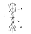
弁体の形状としては、図7〜9に示すように、弁体(1)は平板をベース形状としその外表面に強度向上のための盛り肉部(2)を持たせ、ボス部(3)を太くしたものが知られている。流体抵抗を減らす目的からすると平板の厚みは薄いほど有利であるが、圧力流体を閉止する際に働く流体の推力に抗してその変形を防止するには、所要の厚みを必要とする。そこで、かかる図1の弁体の強度補強を図るために、ボス部に補強板を取り付けた構造が、実用新案登録第2523948号公報に開示されている。流体圧力は、弁体の受圧面積全体に作用し、その推力は弁体中央部ではX軸、Y軸方向に等分に働くが、この公知の弁体ではX軸上に作用する応力に対する補強に過ぎず、実際に働くY軸方向の力に対しては何ら効果を発揮していない問題がある。
【0004】
又、弁体の外円周縁部の形状を工夫して、弁体外円周縁部がシートリングに当接する際、ある開度以下では弁体とシートリングが同時に接触するようにした構造が、実公平4−29164号公報に開示されている。しかしながら、この構造では、弁体外円周縁部が厚肉となり重量が増加すると共に、弁体中央部の強度が不十分となるおそれがあった。
【0005】
【特許文献1】
実用新案登録第2523948号公報
【特許文献2】
実公平4−29164号公報
【0006】
【発明が解決しようとする課題】
この発明は、弁全開時の流量係数を減じることなく、全開及び中間開度における流体抵抗を減じ得ると共に、弁体の軽量化を図り得るようにしたことを課題とする。
【0007】
【課題を解決するための手段】
上記課題を解決するためにこの発明が採った手段は、円板状の弁体のY軸方向上下に弁棒穴用ボス部を外方に膨出して設け、該弁体のノズル側表面とオリフィス側裏面にX軸方向に延びる所定高さの複数の横リブを形成したことを特徴とする。
【0008】
上下の弁棒穴用ボス部を縦リブで連結し、該縦リブを起点として横リブを形成したことを特徴とし、複数の横リブの内中央に位置する横リブをX軸と平行に設け、該中央に位置する横リブの上下に位置する横リブを中央の横リブ方向に角度θで傾斜させて設けたことを特徴とする。
【0009】
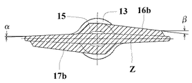
横リブの高さを、弁体周縁に向かって角度βで減少する勾配としたことを特徴とし、弁体の表面に、Y軸を頂点としてZ軸に対して傾斜角αの傾斜を付したことを特徴とする。
【0010】
【発明の実施の形態】
この発明の好ましい実施の形態を、以下に詳細に説明する。この発明は、弁体の弁軸方向であるY軸方向上下に弁棒穴用ボス部を外方に膨出して設け、弁体のノズル側表面にボス部から二次側方向に延びる複数の横リブを、又弁体のオリフィス側裏面にY軸を中心に180゜回転させたボス部から一次側方向に延びる複数の横リブをそれぞれ設けて、リブにより弁体の強度を向上させて弁体の厚みを低減し軽量化を図りうるようにすると共に、流体抵抗を減少させて流量の増加をもたらし得るようにし、更にノズル側とオリフィス側の流速差を減少させて弁体に負荷されるアンバランストルクを抑制するようにしたことを特徴とする。
【0011】
Y軸方向上下に配されたボス部は、縦リブで連結されると共に、ノズル側表面及びオリフィス側裏面の横リブは、縦リブを起点として中央部の横リブはX軸方向に、その上下に位置する横リブは中央部の横リブに平行若しくはθの角度で近接するように配設される。更に、横リブは、好ましくは弁体の厚み方向の中心平面に対して角度βの傾斜角を付ける。又、弁体を構成する円形板は、その表面がY軸を頂点としZ軸に対して傾斜角αの傾斜面に形成されており、Y軸上に弁棒穴用ボス部及び横リブが設けられている。
【0012】
【実施例】
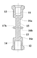
図1〜6を参照して、(10)は中心形バタフライ弁の弁体であり、円板形状をベースとし、図6に示すようにY軸を中心にZ軸に対して角度αの傾斜表面を有している。Y軸上の上下に上下弁棒穴(11)(12)を形成するための上下弁棒穴用ボス部(13)(14)が設けられ、両ボス部は縦リブ(15)で連結される。尚、本明細書においてY軸は、弁体の回転中心軸である弁軸をいい、X軸は弁体の中心においてY軸と直交する軸をいい、Z軸はX軸と直交しY軸と平行な弁体の平面中心を通る軸をいう。
【0013】
弁体(10)のノズル側表面に、複数の横リブ(16a)(16b)(16c)が形成される。横リブは、弁体表面から一定の高さを有して、前記縦リブ(15)を起点として二次側方向にX軸と略平行に延びており、弁体表面近傍を流れる流体は、横リブでその方向が制御される。図示の実施例において横リブは3本形成され、中央の横リブ(16b)はX軸に沿って延びており、その上下の横リブ(16a)(16c)は、X軸に対して角度θで中央の横リブ(16b)に徐々に近接するような傾斜が付けられている。又、各横リブの表面は、Z軸に対して角度βの傾斜角を有して二次側に向かって高さが低くなるように形成されている。
【0014】
又、弁体のオリフィス側裏面に、弁軸Yを中心に180゜回転した状態で前記ノズル側表面と同様に、縦リブ(15)を起点として一次側方向に延びる複数の横リブ(17a)(17b)(17c)が形成されている。横リブ(17)は、図示の実施例では3本形成されている。オリフィス側裏面の横リブ(17)は、ノズル側表面の横リブと同様に、横リブの高さを角度θの傾斜で漸減させると共に、上下の横リブ(17a)(17c)を角度βで中央の横リブに近接させるように設けられている。
【0015】
尚、弁体の表面、裏面は、閉弁時に一次側に対面している面を表面、二次側に対面している面を裏面とし、ノズル側とは、弁体開弁時に二次側に回動する弁体の半分部分(図1において右側半分)をいい、オリフィス側とは、一次側方向に回動する弁体の半分部分(図1において左側半分)をいう。
【0016】
ノズル側表面の3本の横リブ(16)は、一定の高さを有していることにより、弁体表面近傍を流れる流体は、これらの横リブ(16)で方向を制御される。中央の横リブ(16b)は、管内の最大流速部分に位置し最大流速を二分し、且その流速を加速する。中央の横リブ(16b)の上下に配置された横リブ(16a)(16c)は、中央の横リブ(16b)に向かう傾斜が付けられているため、管壁近傍の低速領域の流体を中央の横リブ(16b)に向かわせ、該横リブ(16b)によって加速された流速に引き込まれる状態でその速度を増加させる。流体に対しては、上下弁棒穴用ボス部(13)(14)が流路抵抗となり、ボス部に衝突した流体はボスの二次側で渦を発生させ、流体抵抗を更に増加させる。これに対して、3本の横リブ(16)はボス部の二次側に発生する渦に対して整流効果を発揮し、渦の発生を低減させる。結果として、本発明の横リブは、管内流速を弁体近傍で分断し、整流し、管壁の流体抵抗、弁体表面の流体抵抗を、リブ部が持つ流れ方向制御により補完し、弁全体の流体抵抗を減じる効果を有する。
【0017】
弁体を平板のみで構成した場合、必要な肉厚は計算で求めることが可能であり、弁体中心部が最も発生応力が高く、その応力に相応する肉厚が必要となる。本発明では、上下弁棒穴用ボス部(13)(14)を出来るだけ長くすることにより、ボス部の断面係数を増加し、弁体中央部の肉厚を減じる作用をする。縦リブ(15)の存在は、かかるボス部の作用を助長することが出来る。又、弁体の表裏面の3本の横リはブ、Y軸方向での強度保証として機能させることが出来、平板の肉厚を減じる作用を果たす。かくして、上下弁棒穴用ボス部(13)(14)、縦リブ(15)、横リブ(16)(17)を配することにより、高強度で最軽量の弁体を実現することが出来た。
【0018】
リブを設けることにより、バタフライバルブ全開時の流路面積は減少する。このことは、弁体自身の流体抵抗が増加することを意味しており、結果として全開時のバルブ抵抗を増加させている。しかし、バルブ全開時の流体抵抗は、弁体の投影面積のみならず、弁体に設けられたボス部及び円板の外周先端部にある段差の後流部に発生するカルマン渦により、投影面積以上の流体抵抗が生ずる。本発明の弁体は、横リブ等の存在により投影面積自体は、リブなし弁体に比して増加しているが、ボス部に設けた横リブが前述したような整流効果を発揮し、管中央部の流量を増加させるため、結果としてリブによる投影面積の増加による悪影響を相殺することが出来る。
【0019】
バタフライバルブは、一般に右回り閉で、配管に設置される流体が流れている場合、弁軸側(Y軸上)からみて、図1において左側が一次側、右側が二次側に位置する。流速が増加するに従い、弁体左側が一次側にせり出しているため、流路抵抗が大きく、この部分の流速は低下する(オリフィス効果)。逆に、弁体の右側は、二次側にあるため一次側には抵抗がなく弁体自身の傾き(開度)で流速が加速する(ノズル効果)。この結果、オリフィス側とノズル側では、流速が異なり、弁体オリフィス側の二次側には真空域が発生し、アンバランストルクの原因となる。本発明にあっては、弁体右側はオリフィス側では二次側に、ノズル側では一次側に配置されているため、オリフィス側の後流は横リブにより管中央方向に整流され、ノズル側では横リブが抵抗として働きその流入流速を減ずる。この結果、リブなし弁体に比して本発明の弁体は、オリフィス側とノズル側の流速差を減じる作用をし、アンバランストルクを減少させることが出来る。
【0020】
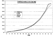
本発明にかかる弁体と従来の弁体との差圧、流量及びCv値を対比した結果を表1及び図10,11,12に示す。尚、従来の弁体は、図7〜9に示すものである。
【0021】
【表1】

【発明の効果】
この発明によれば、弁体のベース円板の肉厚を極限まで薄くすることが出来、弁体全体の重量を軽減させ軽量化を図ることが可能となる。又、管内の流速分布は、管中央部が最速で、管壁に近づくにしたがって管壁との摩擦により低下するが、横リブと角度θの傾斜とにより、管壁部分の低速流体を管中央部の高速流体に吸引させて加速させ、全体の流体抵抗を減少し、流量の増加を図ることができる。更に、アンバランストルクの発生を抑制することが可能となる。
【図面の簡単な説明】
【図1】この発明にかかる弁体の斜視図
【図2】同正面図
【図3】同側面図
【図4】図2IV−IV線に沿った断面図
【図5】弁体の平面図
【図6】図2VI−VI線に沿った断面図
【図7】従来公知の弁体の正面図
【図8】同中央縦断面図
【図9】同平面図
【図10】本発明にかかる弁体と従来の弁体との差圧を対比したグラフ
【図11】本発明にかかる弁体と従来の弁体との流量を対比したグラフ
【図12】本発明にかかる弁体と従来の弁体とのCv値を対比したグラフ
【符号の説明】
(10)弁体
(11)上部弁棒穴
(12)下部弁棒穴
(13)上部弁棒穴用ボス部
(14)下部弁棒穴用ボス部
(15)縦リブ
(16)横リブ
(17)横リブ[0001]
[Field of the Invention]
The present invention relates to a valve body of a butterfly valve that opens and closes a pipeline through which a fluid flows.
[0002]
[Prior art]
2. Description of the Related Art Conventionally, a butterfly valve for opening and closing and controlling a pipeline in which various fluids flow is known. The butterfly valve rotatably supports a disc-shaped valve body in a cylindrical valve body, extends the rotation axis of the valve body out of the valve body, connects to an actuator, and rotates the valve. It has become. The valve element is located at the center of the valve body in the fully opened state in parallel with the pipe direction, and is a factor that reduces the flow path area and also serves as resistance to fluid. As the resistance factor of the valve body acting on the fluid, in addition to the decrease in the flow path area due to the thickness of the valve body, the fluid resistance due to the Karman vortex generated in the step formed by the circumferential end face portion and the boss portion of the valve body. Conceivable.
[0003]
As shown in FIGS. 7 to 9, the valve body (1) has a base shape of a flat plate, and has an embossed portion (2) on its outer surface for improving strength, and a boss portion (3). ) Is known. For the purpose of reducing the fluid resistance, the thinner the flat plate is, the more advantageous it is. However, a required thickness is required to prevent the deformation of the pressurized fluid against the thrust of the fluid acting when closing the fluid. Therefore, in order to reinforce the strength of the valve body shown in FIG. 1, a structure in which a reinforcing plate is attached to a boss portion is disclosed in Japanese Utility Model Registration No. 2523948. Fluid pressure acts on the entire pressure receiving area of the valve body, and the thrust acts equally in the X-axis and Y-axis directions at the center of the valve body, but in this known valve body, reinforcement against stress acting on the X-axis is applied. However, there is a problem that no effect is exerted on the force actually acting in the Y-axis direction.
[0004]
Also, the shape of the outer peripheral edge of the valve body is devised so that when the outer peripheral edge of the valve body comes into contact with the seat ring, the valve body and the seat ring simultaneously contact at a certain opening or less. It is disclosed in Japanese Patent Publication No. Hei 4-29164. However, in this structure, the outer peripheral portion of the valve body is thickened, the weight increases, and the strength of the central portion of the valve body may be insufficient.
[0005]
[Patent Document 1]
Japanese Utility Model Registration No. 2523948 [Patent Document 2]
Japanese Utility Model Publication No. 4-29164 [0006]
[Problems to be solved by the invention]
SUMMARY OF THE INVENTION It is an object of the present invention to reduce the fluid resistance at full opening and intermediate opening without reducing the flow coefficient when the valve is fully opened, and to reduce the weight of the valve body.
[0007]
[Means for Solving the Problems]
Means adopted by the present invention to solve the above-mentioned problem is to provide a valve stem hole boss bulging outwardly above and below the Y-axis direction of a disk-shaped valve body, and to provide a nozzle-side surface of the valve body with a boss portion. A plurality of horizontal ribs having a predetermined height extending in the X-axis direction are formed on the orifice-side back surface.
[0008]
The upper and lower valve stem hole bosses are connected by vertical ribs, and horizontal ribs are formed starting from the vertical ribs. A horizontal rib located at the center of a plurality of horizontal ribs is provided in parallel with the X axis. The horizontal ribs located above and below the central horizontal rib are provided at an angle θ in the direction of the central horizontal rib.
[0009]
The height of the lateral ribs is characterized by a gradient that decreases at an angle β toward the periphery of the valve body, and the surface of the valve body has an inclination angle α with respect to the Z axis with the Y axis as the apex. It is characterized by the following.
[0010]
BEST MODE FOR CARRYING OUT THE INVENTION
Preferred embodiments of the present invention will be described in detail below. The present invention provides a plurality of valve stem hole bosses bulging outwardly in the Y-axis direction, which is the valve axis direction of the valve body, and extending in the secondary direction from the boss portion on the nozzle side surface of the valve body. Horizontal ribs are provided on the back surface of the orifice side of the valve element, and a plurality of horizontal ribs extending in the primary direction from the boss portion rotated by 180 ° about the Y axis are provided on the back surface of the valve element. In addition to reducing the thickness of the body and reducing the weight, the flow resistance can be increased by reducing the fluid resistance, and the flow rate difference between the nozzle side and the orifice side is reduced to load the valve body. It is characterized in that unbalance torque is suppressed.
[0011]
The bosses arranged vertically in the Y-axis direction are connected by vertical ribs, and the horizontal ribs on the nozzle-side surface and the orifice-side rear surface are centered in the X-axis direction starting from the vertical ribs. Is disposed parallel to or adjacent to the central horizontal rib at an angle of θ. Further, the transverse ribs are preferably inclined at an angle β with respect to the center plane in the thickness direction of the valve body. Further, the circular plate constituting the valve body has a surface formed on an inclined surface having an apex of the Y axis and an inclination angle α with respect to the Z axis, and a boss portion for a valve stem hole and a lateral rib are provided on the Y axis. Is provided.
[0012]
【Example】
With reference to FIGS. 1 to 6, (10) is a valve element of a center type butterfly valve, which is based on a disc shape and has an inclination α at an angle α with respect to the Z axis around the Y axis as shown in FIG. It has a surface. Upper and lower valve stem hole bosses (13) and (14) for forming upper and lower valve stem holes (11) and (12) above and below the Y axis are provided, and both bosses are connected by vertical ribs (15). You. In the present specification, the Y axis refers to a valve shaft that is a rotation center axis of the valve body, the X axis refers to an axis perpendicular to the Y axis at the center of the valve body, and the Z axis perpendicular to the X axis and the Y axis. Refers to the axis passing through the center of the plane of the valve body parallel to.
[0013]
A plurality of horizontal ribs (16a) (16b) (16c) are formed on the nozzle-side surface of the valve body (10). The horizontal rib has a certain height from the surface of the valve body, and extends substantially parallel to the X-axis in the secondary direction starting from the vertical rib (15). The direction is controlled by the transverse ribs. In the illustrated embodiment, three horizontal ribs are formed, the central horizontal rib (16b) extends along the X axis, and the upper and lower horizontal ribs (16a) (16c) have an angle θ with respect to the X axis. Thus, an inclination is provided so as to gradually approach the central horizontal rib (16b). The surface of each horizontal rib is formed so as to have an inclination angle of β with respect to the Z axis and to decrease in height toward the secondary side.
[0014]
A plurality of horizontal ribs (17a) extending in the primary direction starting from the vertical ribs (15) on the orifice-side back surface of the valve element, starting from the vertical ribs (15) in a state of being rotated by 180 ° about the valve axis Y, similarly to the nozzle-side surface. (17b) and (17c) are formed. In the illustrated embodiment, three horizontal ribs (17) are formed. Like the horizontal ribs on the nozzle-side surface, the horizontal ribs (17) on the back surface of the orifice gradually decrease the height of the horizontal ribs at an inclination of an angle θ, and the upper and lower horizontal ribs (17a) and (17c) at an angle β. It is provided so as to be close to the central horizontal rib.
[0015]
The front and back surfaces of the valve body are the surface facing the primary side when the valve is closed, the surface facing the secondary side is the back surface, and the nozzle side is the secondary side when the valve is opened. The orifice side refers to a half portion of the valve body (the left half in FIG. 1) that rotates in the primary direction.
[0016]
Since the three lateral ribs (16) on the nozzle side surface have a certain height, the direction of the fluid flowing near the valve element surface is controlled by these lateral ribs (16). The central transverse rib (16b) is located at the maximum flow velocity portion in the pipe, bisects the maximum flow velocity and accelerates the flow velocity. The horizontal ribs (16a) and (16c) arranged above and below the central horizontal rib (16b) are inclined toward the central horizontal rib (16b), so that the fluid in the low-speed region near the pipe wall can be moved to the center. To increase the velocity while being drawn to the flow velocity accelerated by the lateral rib (16b). For the fluid, the bosses (13) and (14) for the upper and lower valve stem holes serve as flow path resistance, and the fluid that collides with the boss generates a vortex on the secondary side of the boss to further increase the fluid resistance. On the other hand, the three lateral ribs (16) exert a rectifying effect on the vortex generated on the secondary side of the boss portion, and reduce the generation of the vortex. As a result, the lateral rib of the present invention divides and rectifies the flow velocity in the pipe near the valve body, complements the fluid resistance of the pipe wall and the fluid resistance of the valve body surface by controlling the flow direction of the rib, and the entire valve. Has the effect of reducing the fluid resistance of
[0017]
When the valve element is composed of only a flat plate, the required thickness can be obtained by calculation, and the central portion of the valve element has the highest generated stress, and a thickness corresponding to the stress is required. In the present invention, by increasing the length of the upper and lower valve stem hole bosses (13) and (14) as much as possible, the section modulus of the boss is increased and the thickness of the central portion of the valve body is reduced. The presence of the vertical rib (15) can promote the function of the boss. Further, the three lateral ribs on the front and back surfaces of the valve body can function as strength guarantee in the direction of the boss and the Y axis, and serve to reduce the thickness of the flat plate. Thus, by disposing the bosses (13) (14), the vertical ribs (15), and the horizontal ribs (16) (17) for the upper and lower valve stem holes, a high-strength and lightest valve body can be realized. Was.
[0018]
By providing the rib, the flow path area when the butterfly valve is fully opened is reduced. This means that the fluid resistance of the valve body itself increases, and as a result, the valve resistance when fully opened. However, the fluid resistance at the time of full opening of the valve depends not only on the projected area of the valve body, but also on the projected area due to the Karman vortex generated in the boss provided on the valve body and the wake part of the step at the outer peripheral tip of the disk. The above fluid resistance occurs. The valve body of the present invention, the projected area itself is increased compared to a valve body without ribs due to the presence of the lateral ribs and the like, but the lateral ribs provided on the boss portion exhibit the rectifying effect as described above, Since the flow rate in the central portion of the tube is increased, the adverse effect of the increase in the projected area due to the rib can be offset as a result.
[0019]
The butterfly valve is generally clockwise closed, and when a fluid installed in the pipe is flowing, the left side is the primary side and the right side is the secondary side in FIG. 1 when viewed from the valve shaft side (on the Y axis). As the flow velocity increases, the left side of the valve body protrudes toward the primary side, so that the flow path resistance increases and the flow velocity in this part decreases (orifice effect). Conversely, since the right side of the valve body is on the secondary side, there is no resistance on the primary side, and the flow velocity is accelerated by the inclination (opening) of the valve body itself (nozzle effect). As a result, the flow velocity is different between the orifice side and the nozzle side, and a vacuum region is generated on the secondary side on the valve body orifice side, causing unbalanced torque. In the present invention, since the valve element right side is disposed on the secondary side on the orifice side and on the nozzle side on the primary side, the downstream flow of the orifice side is rectified by the horizontal rib toward the center of the pipe, and on the nozzle side The lateral ribs act as resistance and reduce their inflow velocity. As a result, the valve element of the present invention acts to reduce the flow velocity difference between the orifice side and the nozzle side as compared with the valve element without ribs, and can reduce unbalance torque.
[0020]
Table 1 and FIGS. 10, 11, and 12 show the results of comparing the differential pressure, the flow rate, and the Cv value between the valve body according to the present invention and the conventional valve body. The conventional valve element is shown in FIGS.
[0021]
[Table 1]
【The invention's effect】
ADVANTAGE OF THE INVENTION According to this invention, the thickness of the base disk of a valve body can be made extremely thin, and the weight of the whole valve body can be reduced and weight reduction can be achieved. Also, the flow velocity distribution in the pipe is the fastest in the center of the pipe, and decreases as the pipe approaches the pipe wall due to friction with the pipe wall. The high-speed fluid in the section can be sucked and accelerated to reduce the overall fluid resistance and increase the flow rate. Further, it is possible to suppress the generation of unbalanced torque.
[Brief description of the drawings]
1 is a perspective view of a valve element according to the present invention. FIG. 2 is a front view of the valve element. FIG. 3 is a side view of the valve element. FIG. 4 is a sectional view taken along the line IV-IV of FIG. 6 is a sectional view taken along the line VI-VI of FIG. 2; FIG. 7 is a front view of a conventionally known valve body; FIG. 8 is a longitudinal sectional view at the center; FIG. 9 is a plan view of the valve body; FIG. FIG. 11 is a graph comparing a differential pressure between a valve element and a conventional valve element. FIG. 11 is a graph comparing a flow rate between a valve element according to the present invention and a conventional valve element. FIG. 12 is a graph comparing a valve element according to the present invention and a conventional valve element. Graph comparing Cv value with valve body [Explanation of symbols]
(10) Valve body (11) Upper valve stem hole (12) Lower valve stem hole (13) Boss portion for upper valve stem hole (14) Boss portion for lower valve stem hole (15) Vertical rib (16) Horizontal rib ( 17) Side rib
Claims (5)
Priority Applications (3)
| Application Number | Priority Date | Filing Date | Title |
|---|---|---|---|
| JP2003028883A JP3676785B2 (en) | 2003-02-05 | 2003-02-05 | Butterfly valve disc |
| KR1020030031076A KR100609739B1 (en) | 2003-02-05 | 2003-05-16 | Butterfly valve disk |
| CNB031493262A CN100376828C (en) | 2003-02-05 | 2003-06-26 | Valve body of miter valve |
Applications Claiming Priority (1)
| Application Number | Priority Date | Filing Date | Title |
|---|---|---|---|
| JP2003028883A JP3676785B2 (en) | 2003-02-05 | 2003-02-05 | Butterfly valve disc |
Publications (2)
| Publication Number | Publication Date |
|---|---|
| JP2004239343A true JP2004239343A (en) | 2004-08-26 |
| JP3676785B2 JP3676785B2 (en) | 2005-07-27 |
Family
ID=32956208
Family Applications (1)
| Application Number | Title | Priority Date | Filing Date |
|---|---|---|---|
| JP2003028883A Expired - Fee Related JP3676785B2 (en) | 2003-02-05 | 2003-02-05 | Butterfly valve disc |
Country Status (3)
| Country | Link |
|---|---|
| JP (1) | JP3676785B2 (en) |
| KR (1) | KR100609739B1 (en) |
| CN (1) | CN100376828C (en) |
Cited By (3)
| Publication number | Priority date | Publication date | Assignee | Title |
|---|---|---|---|---|
| JP2007032683A (en) * | 2005-07-26 | 2007-02-08 | Toyo Valve Co Ltd | Butterfly valve |
| CN106246934A (en) * | 2016-10-18 | 2016-12-21 | 广州九陌机电设备有限公司 | A kind of valve |
| US11035474B2 (en) | 2018-09-04 | 2021-06-15 | Bueno Technology Co., Ltd. | Fluoroplastic butterfly valve structure |
Families Citing this family (8)
| Publication number | Priority date | Publication date | Assignee | Title |
|---|---|---|---|---|
| CN1975220B (en) * | 2006-11-22 | 2011-03-02 | 杨耀德 | Butterfly valve core and butterfly valve thereof |
| KR100870921B1 (en) * | 2008-01-10 | 2008-11-28 | 주식회사 한창엔텍 | Butterfly valve |
| JP4659927B1 (en) * | 2010-04-13 | 2011-03-30 | 株式会社巴技術研究所 | Butterfly valve body |
| KR101894923B1 (en) | 2016-11-10 | 2018-09-04 | 동아대학교 산학협력단 | Butterfly Balve |
| KR101919588B1 (en) | 2016-12-20 | 2018-11-19 | 동아대학교 산학협력단 | Butterfly Balve of Bidirectional Opening And Closing Type |
| TWI782167B (en) * | 2018-01-10 | 2022-11-01 | 日商旭有機材股份有限公司 | Eccentric butterfly valve |
| CN109667940B (en) * | 2018-11-21 | 2022-09-02 | 中国北方车辆研究所 | Butterfly valve plate of hydraulic retarder and design method |
| CN113490808A (en) | 2019-02-28 | 2021-10-08 | 株式会社开滋 | Valve body of double-eccentric butterfly valve and double-eccentric butterfly valve |
Family Cites Families (6)
| Publication number | Priority date | Publication date | Assignee | Title |
|---|---|---|---|---|
| US3960177A (en) * | 1975-03-12 | 1976-06-01 | Baumann Hans D | Low torque and low noise butterfly valve disc |
| US4243203A (en) * | 1979-07-20 | 1981-01-06 | Mack Lawrence W | Butterfly valve |
| JPS59153769U (en) * | 1983-03-31 | 1984-10-15 | 積水化学工業株式会社 | butterfly valve valve body |
| JPH035724Y2 (en) * | 1986-07-18 | 1991-02-14 | ||
| JPS6412337A (en) * | 1987-07-06 | 1989-01-17 | Fujitsu Ltd | Method for deciding value in selection of processing |
| US6354567B1 (en) * | 1999-06-29 | 2002-03-12 | Siemens Canada Limited | Throttle shaft and butterfly construction |
-
2003
- 2003-02-05 JP JP2003028883A patent/JP3676785B2/en not_active Expired - Fee Related
- 2003-05-16 KR KR1020030031076A patent/KR100609739B1/en active IP Right Grant
- 2003-06-26 CN CNB031493262A patent/CN100376828C/en not_active Expired - Lifetime
Cited By (4)
| Publication number | Priority date | Publication date | Assignee | Title |
|---|---|---|---|---|
| JP2007032683A (en) * | 2005-07-26 | 2007-02-08 | Toyo Valve Co Ltd | Butterfly valve |
| JP4713971B2 (en) * | 2005-07-26 | 2011-06-29 | 東洋バルヴ株式会社 | Butterfly valve |
| CN106246934A (en) * | 2016-10-18 | 2016-12-21 | 广州九陌机电设备有限公司 | A kind of valve |
| US11035474B2 (en) | 2018-09-04 | 2021-06-15 | Bueno Technology Co., Ltd. | Fluoroplastic butterfly valve structure |
Also Published As
| Publication number | Publication date |
|---|---|
| CN100376828C (en) | 2008-03-26 |
| CN1519496A (en) | 2004-08-11 |
| JP3676785B2 (en) | 2005-07-27 |
| KR100609739B1 (en) | 2006-08-09 |
| KR20040071040A (en) | 2004-08-11 |
Similar Documents
| Publication | Publication Date | Title |
|---|---|---|
| JP3676785B2 (en) | Butterfly valve disc | |
| EP1588082B1 (en) | Butterfly valve | |
| JP5286361B2 (en) | Air spill valve | |
| JP4039561B2 (en) | High stability valve device for governor valve | |
| WO2017133370A1 (en) | Fan impeller and fan using fan impeller | |
| JP4663259B2 (en) | Blower and vacuum cleaner | |
| KR101476518B1 (en) | Valve element of butterfly valve | |
| JP3676795B1 (en) | Butterfly valve disc | |
| JP3709196B1 (en) | Triple eccentric butterfly valve and valve body | |
| JP3086793B2 (en) | Butterfly valve | |
| CN110741194B (en) | Filling valve with main valve | |
| JP2010190221A (en) | Blower | |
| JPH06229395A (en) | Impeller for air blower | |
| JPH09296799A (en) | Impeller of centrifugal compressor | |
| JP3086792B2 (en) | Butterfly valve | |
| JP5171920B2 (en) | Butterfly valve | |
| KR20170109965A (en) | Ball for valve and ball valve with the same | |
| JPH03267506A (en) | Stationary blade of axial flow turbine | |
| CN214465092U (en) | Accelerating type centrifugal impeller and fan assembly with same | |
| JPH0353089Y2 (en) | ||
| WO1997033091A1 (en) | Propeller fan and outdoor machine using the same for air-conditioners | |
| CN103807469B (en) | A kind of flap of oblique flap valve | |
| KR100870921B1 (en) | Butterfly valve | |
| JP2005233294A (en) | Manufacturing method for valve element for center type butterfly valve | |
| JPH1163293A (en) | Butterfly valve and machining method thereof |
Legal Events
| Date | Code | Title | Description |
|---|---|---|---|
| A871 | Explanation of circumstances concerning accelerated examination |
Free format text: JAPANESE INTERMEDIATE CODE: A871 Effective date: 20040722 |
|
| A975 | Report on accelerated examination |
Free format text: JAPANESE INTERMEDIATE CODE: A971005 Effective date: 20040910 |
|
| A131 | Notification of reasons for refusal |
Free format text: JAPANESE INTERMEDIATE CODE: A131 Effective date: 20040921 |
|
| A521 | Request for written amendment filed |
Free format text: JAPANESE INTERMEDIATE CODE: A523 Effective date: 20041118 |
|
| A521 | Request for written amendment filed |
Free format text: JAPANESE INTERMEDIATE CODE: A523 Effective date: 20041119 |
|
| TRDD | Decision of grant or rejection written | ||
| A01 | Written decision to grant a patent or to grant a registration (utility model) |
Free format text: JAPANESE INTERMEDIATE CODE: A01 Effective date: 20050405 |
|
| A61 | First payment of annual fees (during grant procedure) |
Free format text: JAPANESE INTERMEDIATE CODE: A61 Effective date: 20050428 |
|
| R150 | Certificate of patent or registration of utility model |
Ref document number: 3676785 Country of ref document: JP Free format text: JAPANESE INTERMEDIATE CODE: R150 Free format text: JAPANESE INTERMEDIATE CODE: R150 |
|
| FPAY | Renewal fee payment (event date is renewal date of database) |
Free format text: PAYMENT UNTIL: 20080513 Year of fee payment: 3 |
|
| FPAY | Renewal fee payment (event date is renewal date of database) |
Free format text: PAYMENT UNTIL: 20110513 Year of fee payment: 6 |
|
| R250 | Receipt of annual fees |
Free format text: JAPANESE INTERMEDIATE CODE: R250 |
|
| FPAY | Renewal fee payment (event date is renewal date of database) |
Free format text: PAYMENT UNTIL: 20110513 Year of fee payment: 6 |
|
| FPAY | Renewal fee payment (event date is renewal date of database) |
Free format text: PAYMENT UNTIL: 20140513 Year of fee payment: 9 |
|
| R250 | Receipt of annual fees |
Free format text: JAPANESE INTERMEDIATE CODE: R250 |
|
| R250 | Receipt of annual fees |
Free format text: JAPANESE INTERMEDIATE CODE: R250 |
|
| S111 | Request for change of ownership or part of ownership |
Free format text: JAPANESE INTERMEDIATE CODE: R313113 |
|
| S531 | Written request for registration of change of domicile |
Free format text: JAPANESE INTERMEDIATE CODE: R313531 |
|
| R350 | Written notification of registration of transfer |
Free format text: JAPANESE INTERMEDIATE CODE: R350 |
|
| R250 | Receipt of annual fees |
Free format text: JAPANESE INTERMEDIATE CODE: R250 |
|
| R250 | Receipt of annual fees |
Free format text: JAPANESE INTERMEDIATE CODE: R250 |
|
| LAPS | Cancellation because of no payment of annual fees |